
Process Stability, Microstructure and Mechanical Properties of Underwater Submerged-Arc Welded Steel

 , and
, and
Abstract
:
1. Introduction
2. Materials and Methods
3. Results and Discussion
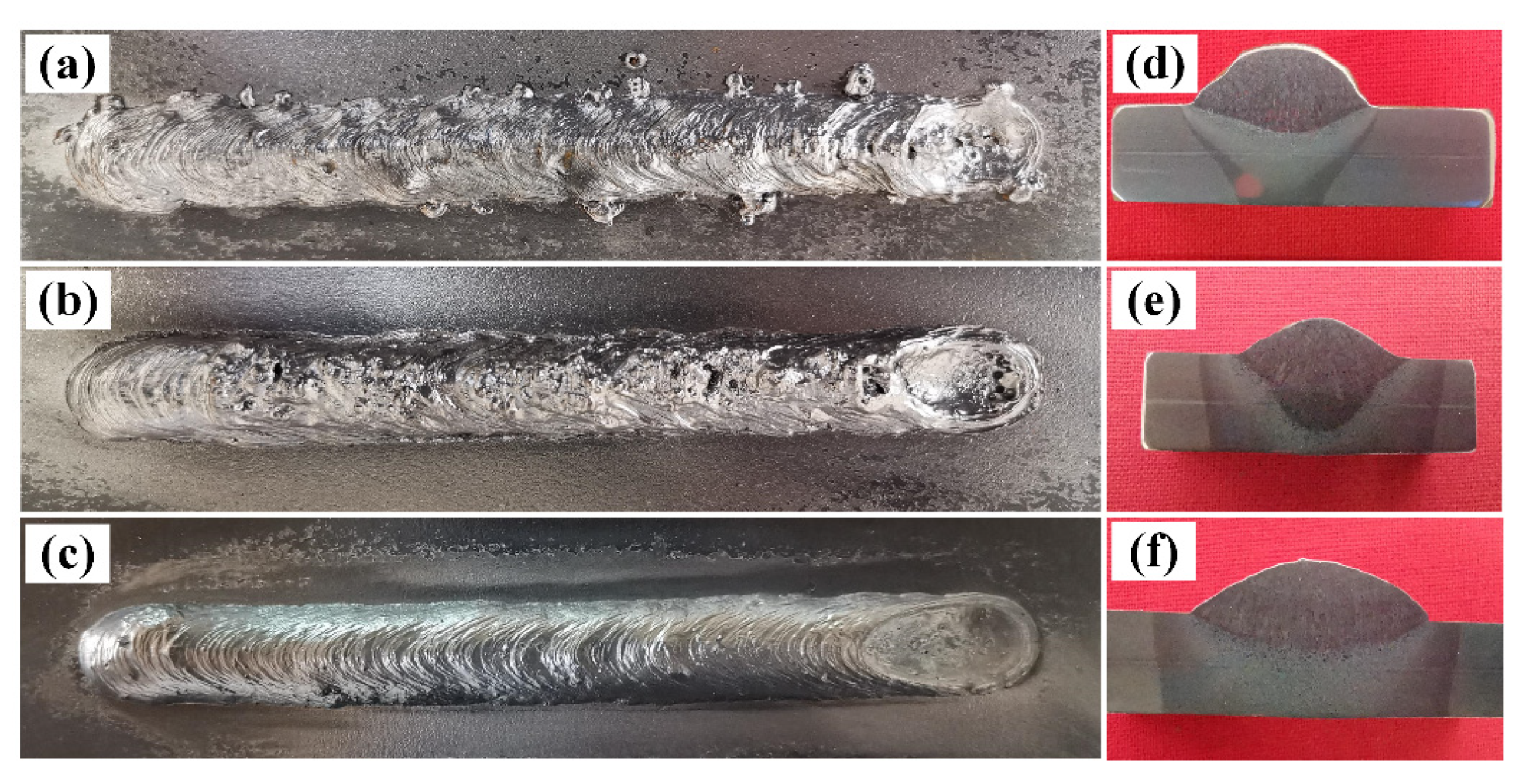
3.1. Welds Appearance
3.2. Geometry Statistics of Welds Formation
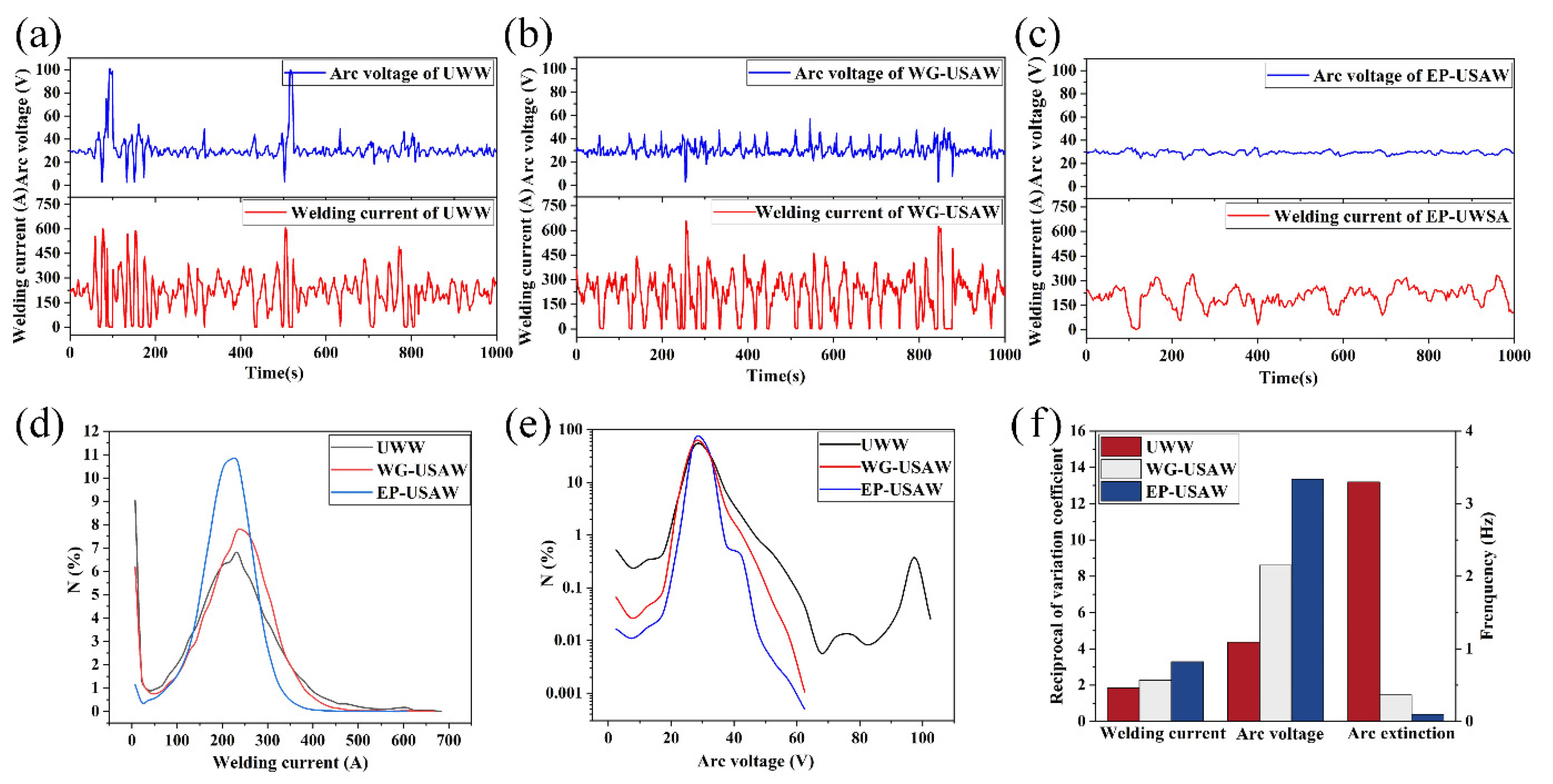
3.3. Welding Process Stability
3.4. Slag Structure
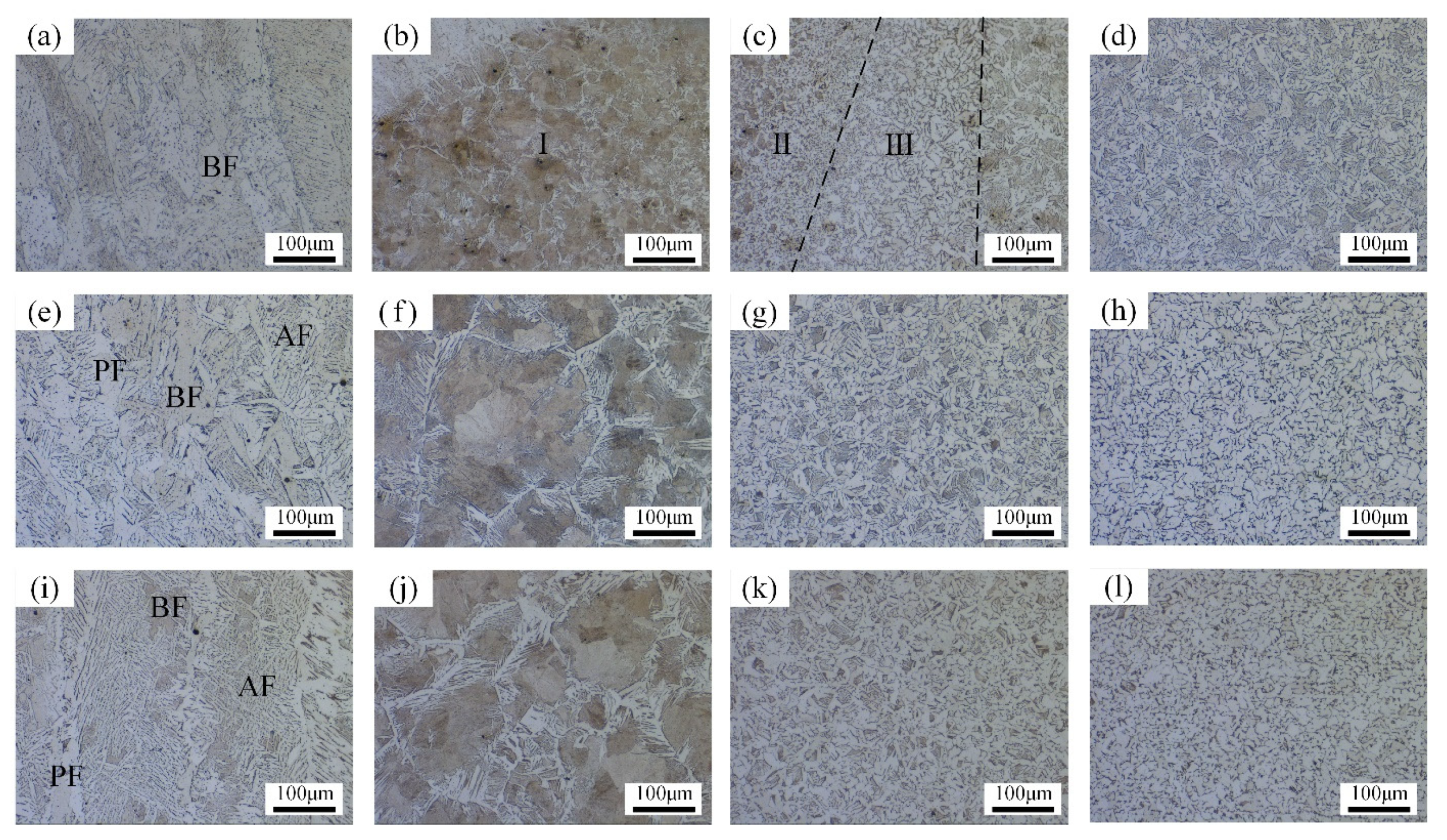
3.5. Microstructure
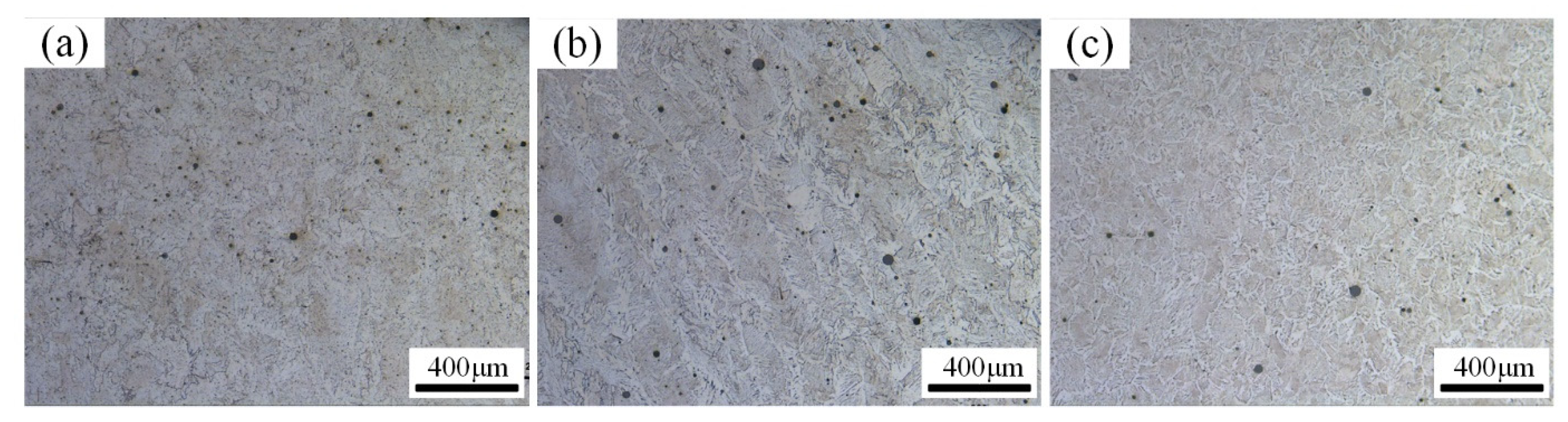
3.6. Pores
3.7. Mechanical Properties
4. Conclusions
- The addition of mixture with water glass significantly increases the process stability, weld penetration and ultimate strength, but deteriorates the weld formation, furthermore, the porosity of the joint is as high as 0.75%, which may hinder the comprehensive improvement in mechanical properties of the joint.
- The epoxy resin in the mixture completely isolates the surrounding water from the welding area, which modifies the arc burning environment and welds formation, thus greatly improving the process stability.
- Compared with the other two methods, the microstructure of the joints obtained by using the epoxy resin-containing mixture is filled with massive fine acicular ferrite, and the comprehensive mechanical properties are completely improved.
- Compared with underwater wet welding, the joints’ average elongation, ultimate strength and room temperature impact toughness of underwater submerged-arc welding with the mixture of epoxy resin increased by 178.4%, 10.1% and 69.1%, respectively. The bending angle of the joint reaches to 180°. The HAZ maximum hardness is reduced by 24.5%.
Author Contributions
Funding
Institutional Review Board Statement
Informed Consent Statement
Data Availability Statement
Acknowledgments
Conflicts of Interest
References
- Pessoa, E.C.P.; Liu, S. The State of the Art of Underwater Wet Welding Practice: Part 2. Weld. J. 2021, 100, 171–182. [Google Scholar] [CrossRef]
- Tomków, J.; Fydrych, D.; Rogalski, G.; Łabanowski, J. Temper Bead Welding of S460N Steel in Wet Welding Conditions. Adv. Mater. Sci. 2018, 18, 5–14. [Google Scholar] [CrossRef] [Green Version]
- Yushchenko, K.A.; Gretskii, Y.Y.; Maksimov, S.Y. Study of physico-metallurgical peculiarities of wet arc welding of structural steels. In Proceedings of the Underwater Wet Welding and Cutting, International Seminar and Workshop, TWI North, Middlesbrough; Woodhead Publisher: Cambridge, UK, 1997; pp. 17–18. [Google Scholar]
- Jia, C.; Zhang, Y.; Zhao, B.; Hu, J.K.; Wu, C. Visual sensing of the physical process during underwater wet FCAW. Weld. J. 2016, 95, 202–209. [Google Scholar]
- de Rosa Oliveira, F.; Rodrigues Soares, W.; Queiroz Bracarense, A. Study correlating the bubble phenomenon and electrical signals in underwater wet welding with covered electrodes. Weld. Int. 2015, 29, 363–371. [Google Scholar] [CrossRef]
- Maksimov, S.Y. Underwater arc welding of higher strength low-alloy steels. Weld. Int. 2010, 24, 449–454. [Google Scholar] [CrossRef]
- Fydrych, D.; Świerczyńska, A.; Rogalski, G. Effect of underwater wet welding conditions on the diffusible hydrogen content in deposited metal. Metall. Ital. 2015, 1, 6–8. [Google Scholar]
- Jia, C.; Zhang, Y.; Wu, J.; Xing, C.; Zhao, B.; Chuansong, W. Comprehensive analysis of spatter loss in wet FCAW considering interactions of bubbles, droplets and arc—Part 2: Visualization & mechanisms. J. Manuf. Process. 2019, 40, 105–112. [Google Scholar]
- Tsai, C.L.; Masubuchi, K. Mechanisms of rapid cooling in underwater welding. Appl. Ocean. Res. 1979, 1, 99–110. [Google Scholar] [CrossRef]
- Wang, J.; Sun, Q.; Wu, L.; Liu, Y.; Teng, J.; Feng, J. Effect of ultrasonic vibration on microstructural evolution and mechanical properties of underwater wet welding joint. J. Mater. Process. Technol. 2017, 246, 185–197. [Google Scholar] [CrossRef]
- Sun, Q.J.; Cheng, W.Q.; Liu, Y.B.; Wang, J.F.; Cai, C.W.; Feng, J.C. Microstructure and mechanical properties of ultrasonic assisted underwater wet welding joints. Mater. Des. 2016, 103, 63–70. [Google Scholar] [CrossRef]
- Zhang, H.; Dai, X.Y.; Feng, J.; Hu, L.L. Preliminary investigation on real-time induction heating-assisted underwater wet welding. Weld. J. 2015, 94, 8–15. [Google Scholar]
- Fydrych, D.; Świerczyńska, A.; Rogalski, G.; Łabanowski, J. Temper bead welding of S420G2+ M steel in water environment. Adv. Mater. Sci. 2016, 16, 5–16. [Google Scholar] [CrossRef] [Green Version]
- Tomków, J.; Fydrych, D.; Wilk, K. Effect of electrode waterproof coating on quality of underwater wet welded joints. Materials 2020, 13, 2947. [Google Scholar] [CrossRef]
- Tomków, J. Weldability of underwater wet-welded HSLA steel: Effects of electrode hydrophobic coatings. Materials 2021, 14, 1364. [Google Scholar] [CrossRef]
- Gao, W.; Wang, D.; Cheng, F.; Deng, C.; Liu, Y.; Xu, W. Enhancement of the fatigue strength of underwater wet welds by grinding and ultrasonic impact treatment. J. Mater. Process. Technol. 2015, 223, 305–312. [Google Scholar] [CrossRef]
- Guo, N.; Du, Y.; Maksimov, S.Y.; Feng, J.; Yin, Z.; Krazhanovskyi, D.; Fu, Y. Study of metal transfer control in underwater wet FCAW using pulsed wire feed method. Weld. World 2018, 62, 87–94. [Google Scholar] [CrossRef]
- Wang, J.; Sun, Q.; Zhang, S.; Wang, C.; Wu, L.; Feng, J. Characterization of the underwater welding arc bubble through a visual sensing method. J. Mater. Process. Technol. 2018, 251, 95–108. [Google Scholar] [CrossRef]
- Bogusz, A.; Masset, P.J. High temperature diffusion processes at the metal/slag interface. In Proceedings of the Defect and Diffusion Forum; Trans Tech Publications Ltd.: Bäch, Swizerland, 2012; Volume 323, pp. 115–120. [Google Scholar]
- Dong, S.; Han, Y.; Jia, C.; Wu, C.; Zhang, M.; Yang, Q.; Yang, J. Organic Adhesive Assisted Underwater Submerged-arc Welding. J. Mater. Process. Tech. 2020, 284, 116739. [Google Scholar] [CrossRef]
- Han, Y.; Dong, S.; Zhang, M.; Jia, C.; Zhang, M.; Wu, C. A novel underwater submerged-arc welding acquires sound quality joints for high strength marine steel. Mater. Lett. 2020, 261, 127075. [Google Scholar] [CrossRef]
- Santos, V.R.; Monteiro, M.J.; Rizzo, F.C.; Bracarense, A.Q.; Pessoa, E.C.P.; Marinho, R.R.; Vieira, L.A. Development of an oxyrutile electrode for wet welding. Weld. J. 2012, 91, 319–328. [Google Scholar]
- Suga, Y.; Hasui, A. On Formation of Porosity in Underwater Weld Metal (The 1st Report)-Effect of Water Pressure on Formation of Porosity. Trans. Japan Weld. Soc. 1986, 17, 58–64. [Google Scholar]


| SiO2 | CaO | Al2O3 + MnO | CaF2 | FeO | K2O | Na2O | |
|---|---|---|---|---|---|---|---|
| HJ350 | 30–35 | 10–20 | 27–37 | 14–20 | ≤1.0 | - | - |
| Water glass | 30.24 | - | - | - | - | 3.53 | 10.87 |
| C | Si | Mn | S | P | |
|---|---|---|---|---|---|
| Base metal | 0.20 | 0.30 | 0.70 | 0.035 | 0.045 |
| Weld metal | 0.11 | 0.15 | 0.30 | 0.025 | 0.020 |
| Arc Voltage (V) | Wire Feed Rate (m/min) | Welding Speed (mm/min) | Wire Extension (mm) | Water Depth (m) |
|---|---|---|---|---|
| 30 | 5 | 130 | 15 | 0.3 |
| Welding Method | Sample No. | Elongation (%) | Ultimate Strength (MPa) |
|---|---|---|---|
| UWW | 1 | 6.0 | 423 |
| 2 | 6.8 | 413 | |
| 3 | 8.4 | 415 | |
| WG-USAW | 1 | 9.2 | 445 |
| 2 | 8.2 | 458 | |
| 3 | 7.5 | 442 | |
| EP-USAW | 1 | 13.7 | 463 |
| 2 | 12.7 | 463 | |
| 3 | 19.5 | 451 |
Publisher’s Note: MDPI stays neutral with regard to jurisdictional claims in published maps and institutional affiliations. |
© 2021 by the authors. Licensee MDPI, Basel, Switzerland. This article is an open access article distributed under the terms and conditions of the Creative Commons Attribution (CC BY) license (https://creativecommons.org/licenses/by/4.0/).
Share and Cite
Zhang, M.; Han, Y.; Jia, C.; Dong, S.; Maksimov, S.; Wu, C. Process Stability, Microstructure and Mechanical Properties of Underwater Submerged-Arc Welded Steel. Metals 2021, 11, 1249. https://doi.org/10.3390/met11081249
Zhang M, Han Y, Jia C, Dong S, Maksimov S, Wu C. Process Stability, Microstructure and Mechanical Properties of Underwater Submerged-Arc Welded Steel. Metals. 2021; 11(8):1249. https://doi.org/10.3390/met11081249
Chicago/Turabian StyleZhang, Maofu, Yanfei Han, Chuanbao Jia, Shengfa Dong, Sergii Maksimov, and Chuansong Wu. 2021. "Process Stability, Microstructure and Mechanical Properties of Underwater Submerged-Arc Welded Steel" Metals 11, no. 8: 1249. https://doi.org/10.3390/met11081249
APA StyleZhang, M., Han, Y., Jia, C., Dong, S., Maksimov, S., & Wu, C. (2021). Process Stability, Microstructure and Mechanical Properties of Underwater Submerged-Arc Welded Steel. Metals, 11(8), 1249. https://doi.org/10.3390/met11081249