
Influence of Alumina Nanofibers Sintered by the Spark Plasma Method on Nickel Mechanical Properties

 ,
,  ,
, 
Abstract
1. Introduction
2. Materials and Methods
3. Results
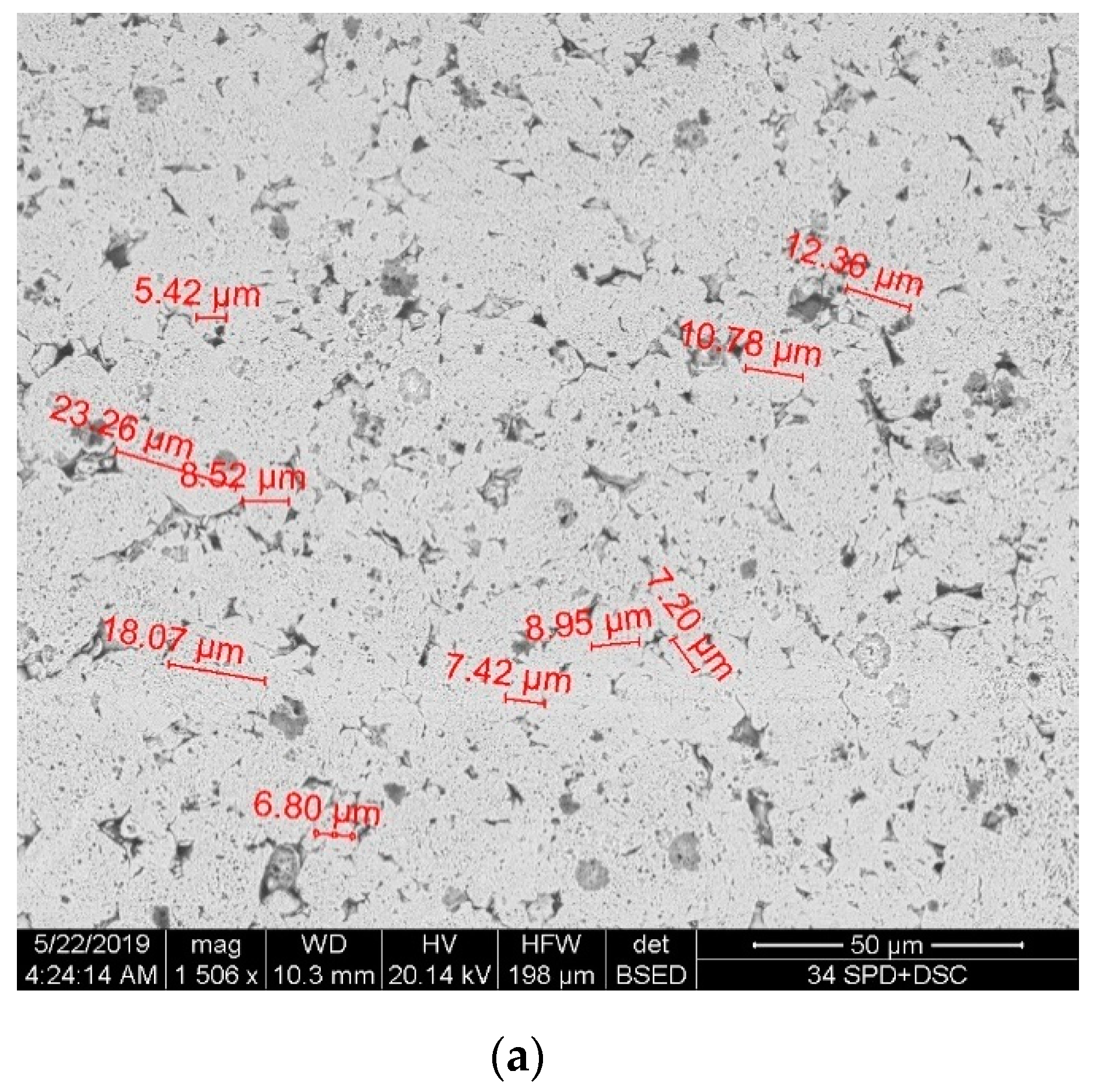
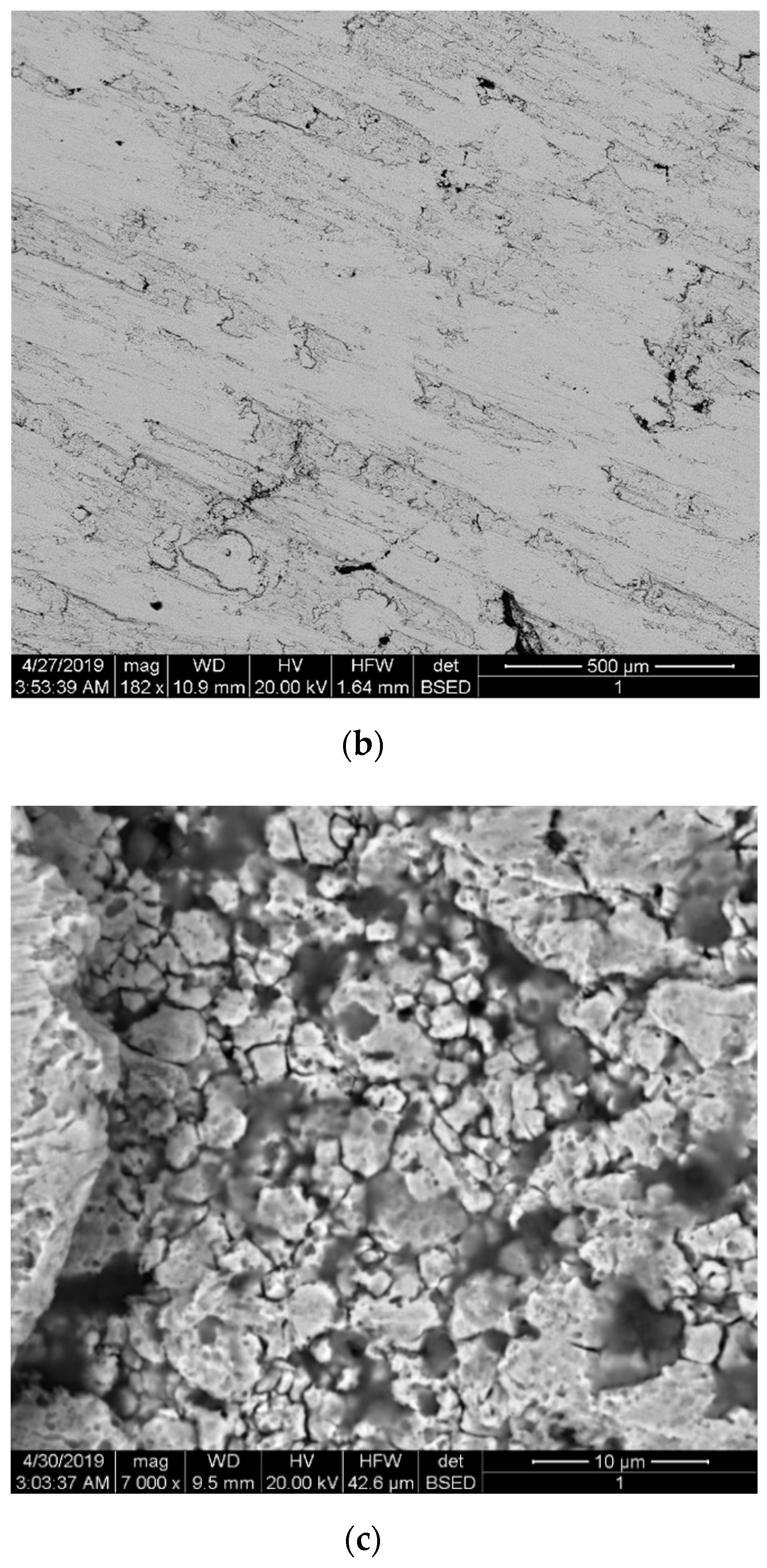
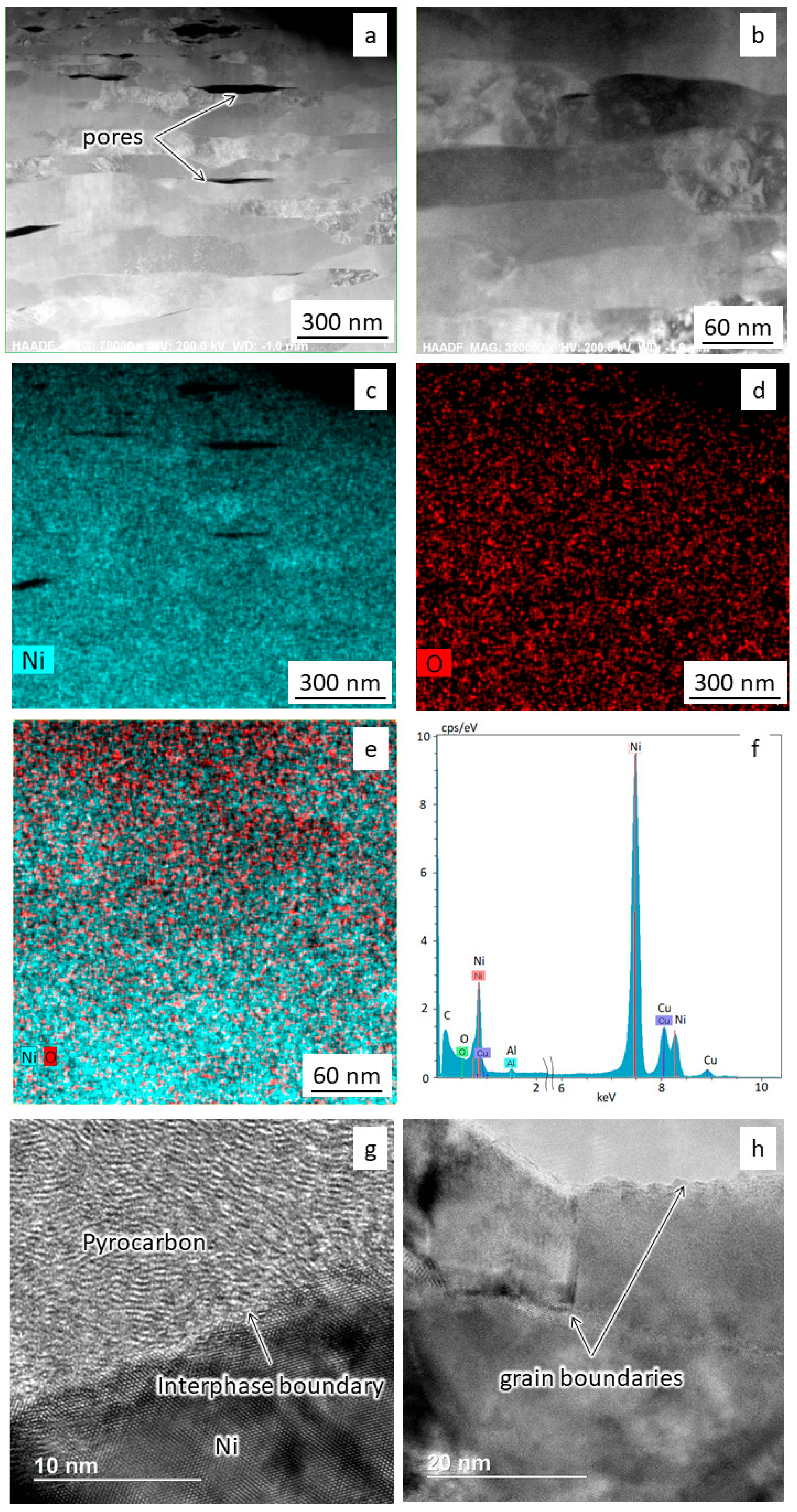
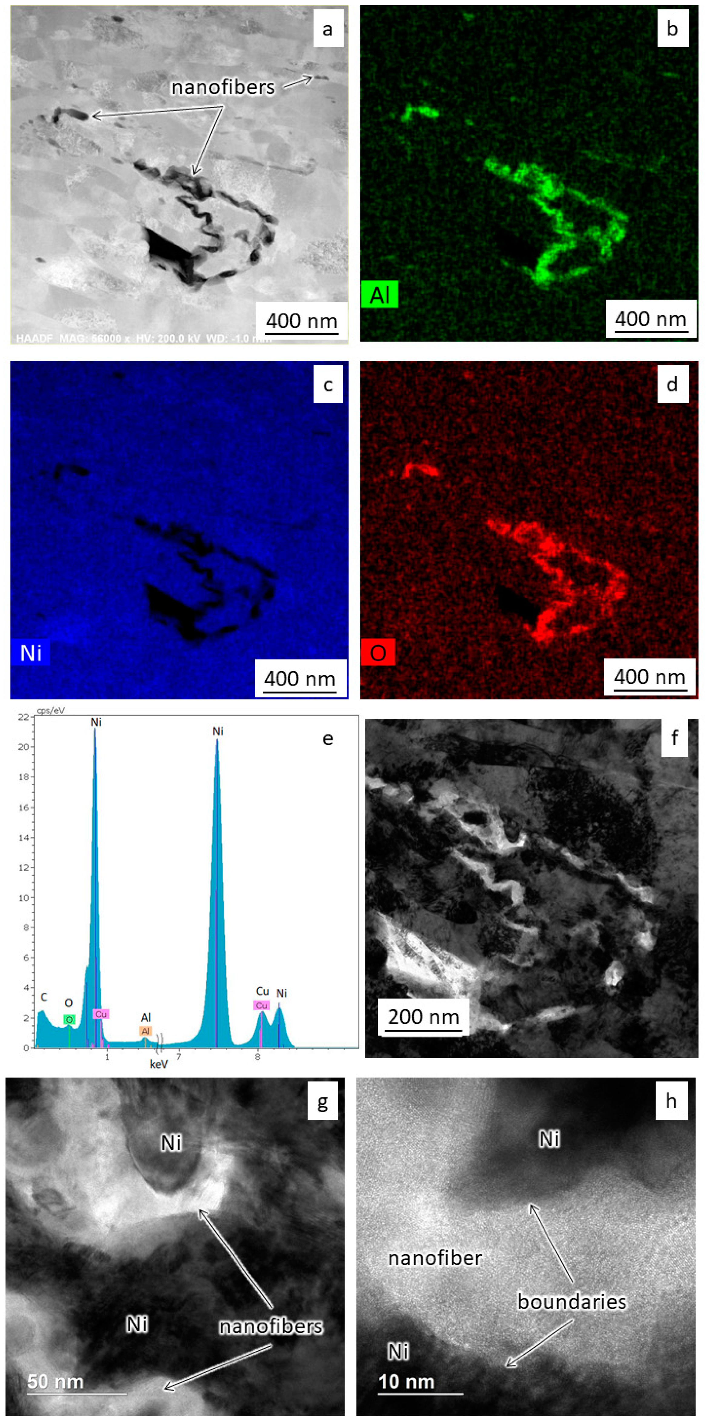
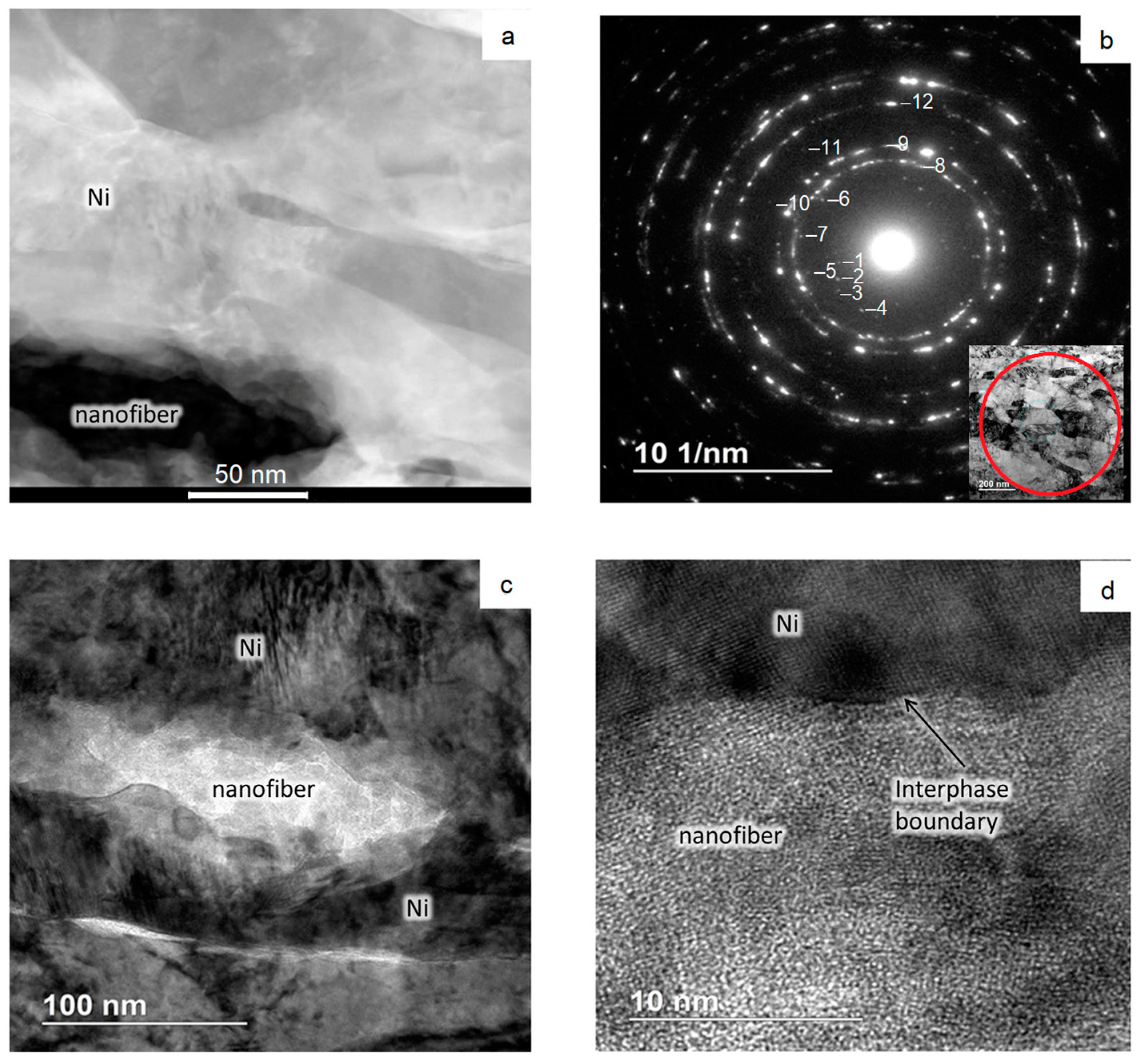
3.1. Microstructure
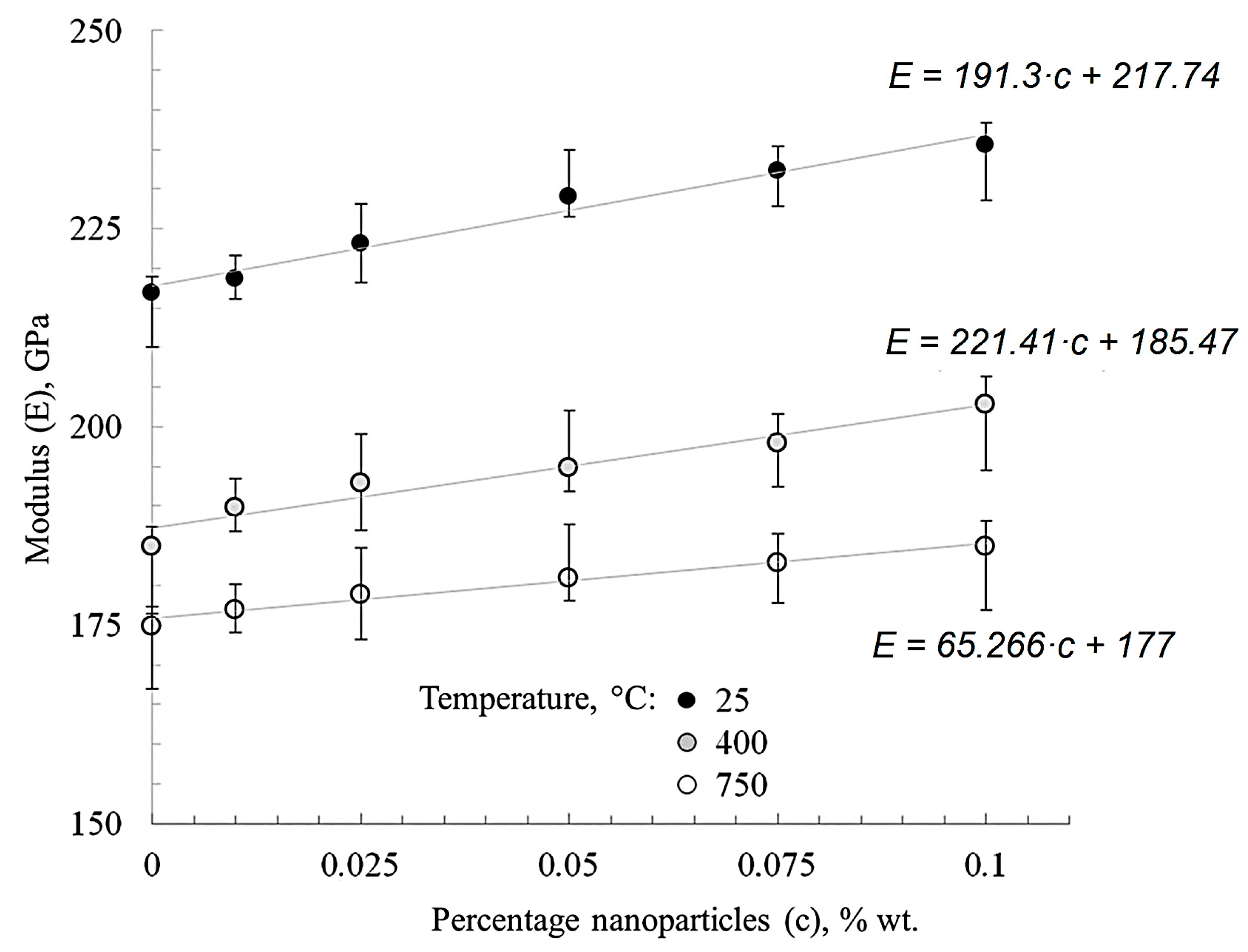
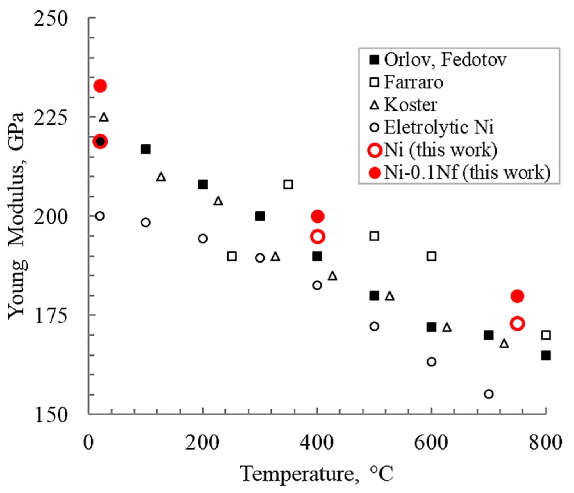
3.2. Elastic properties
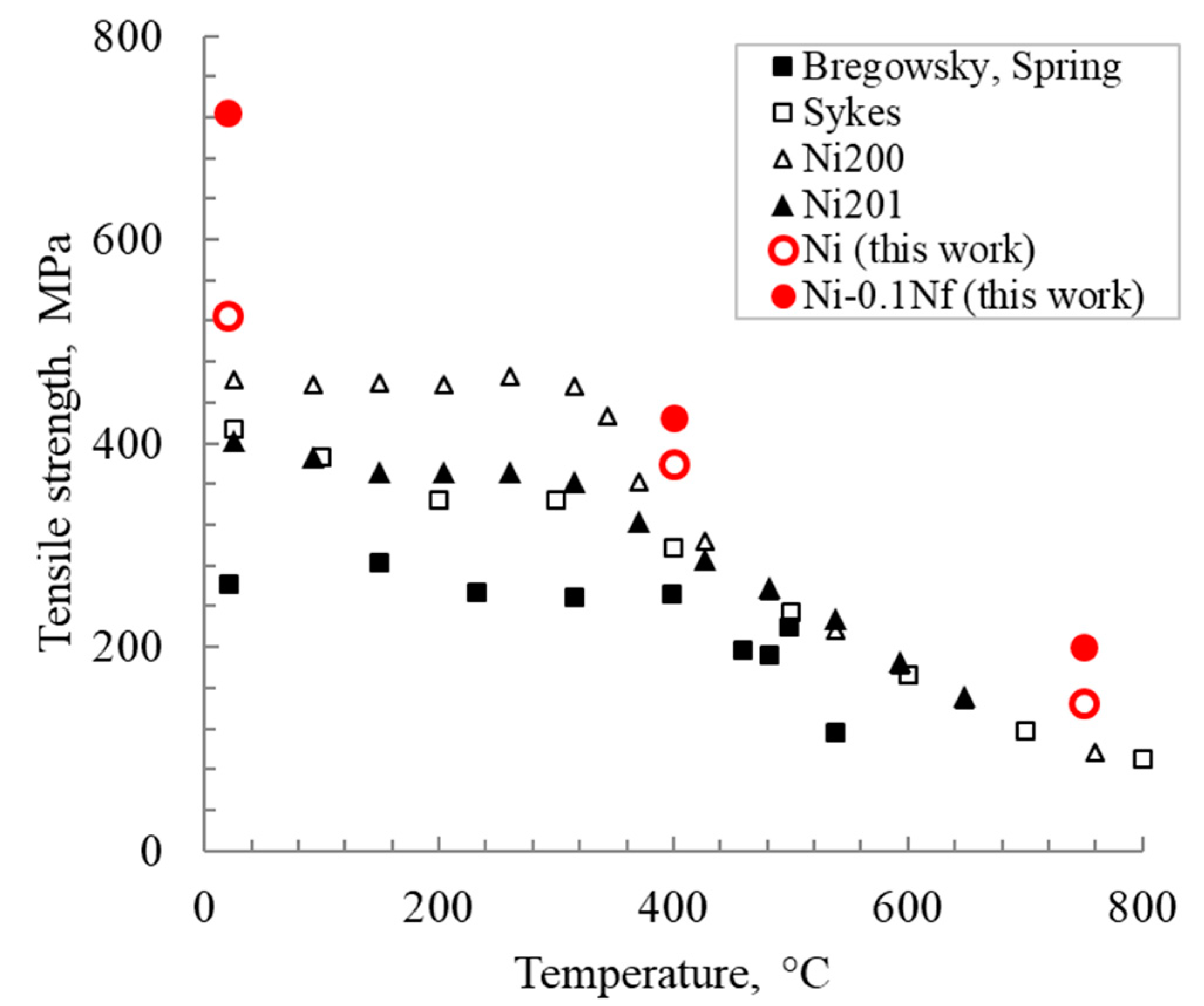
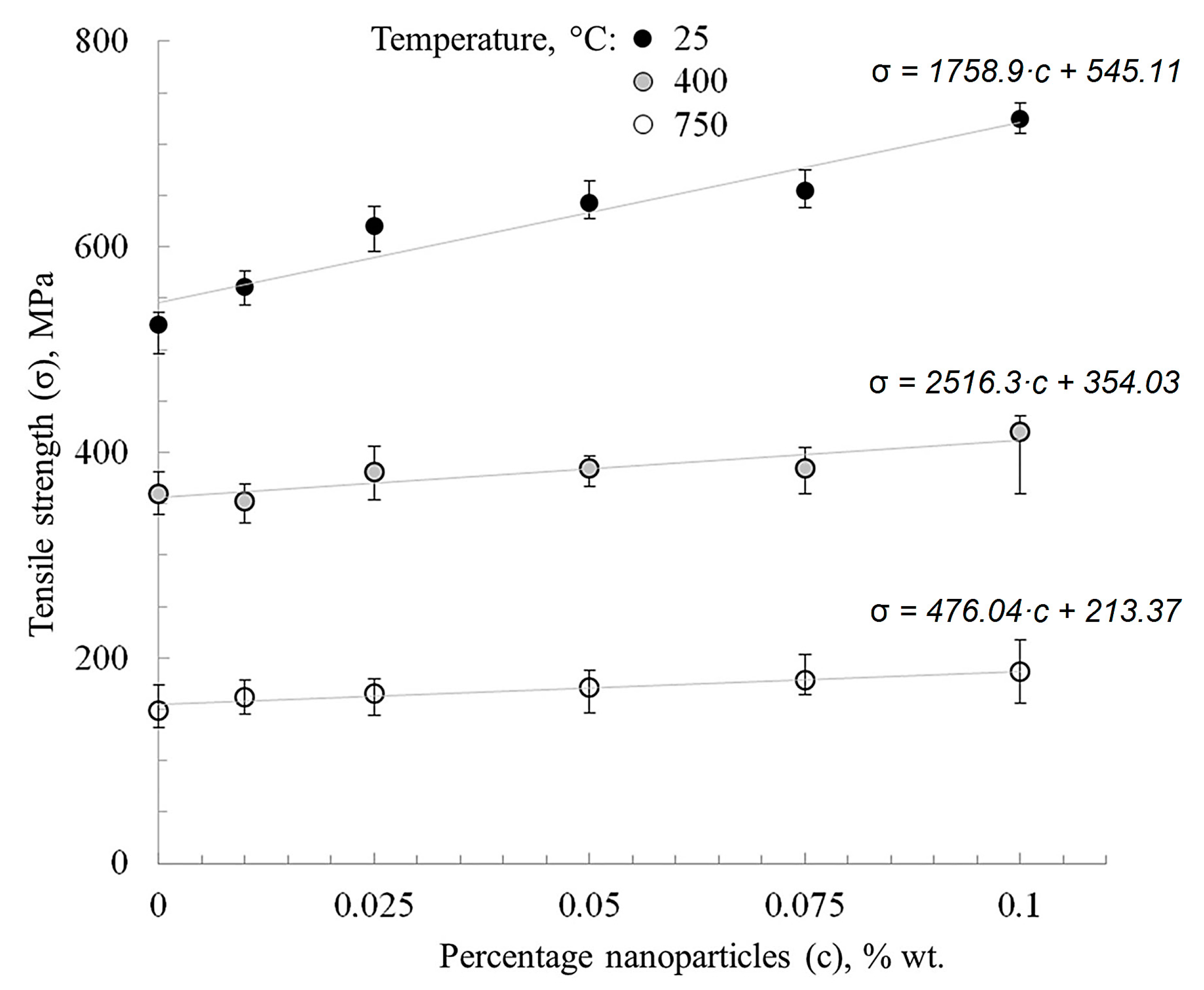
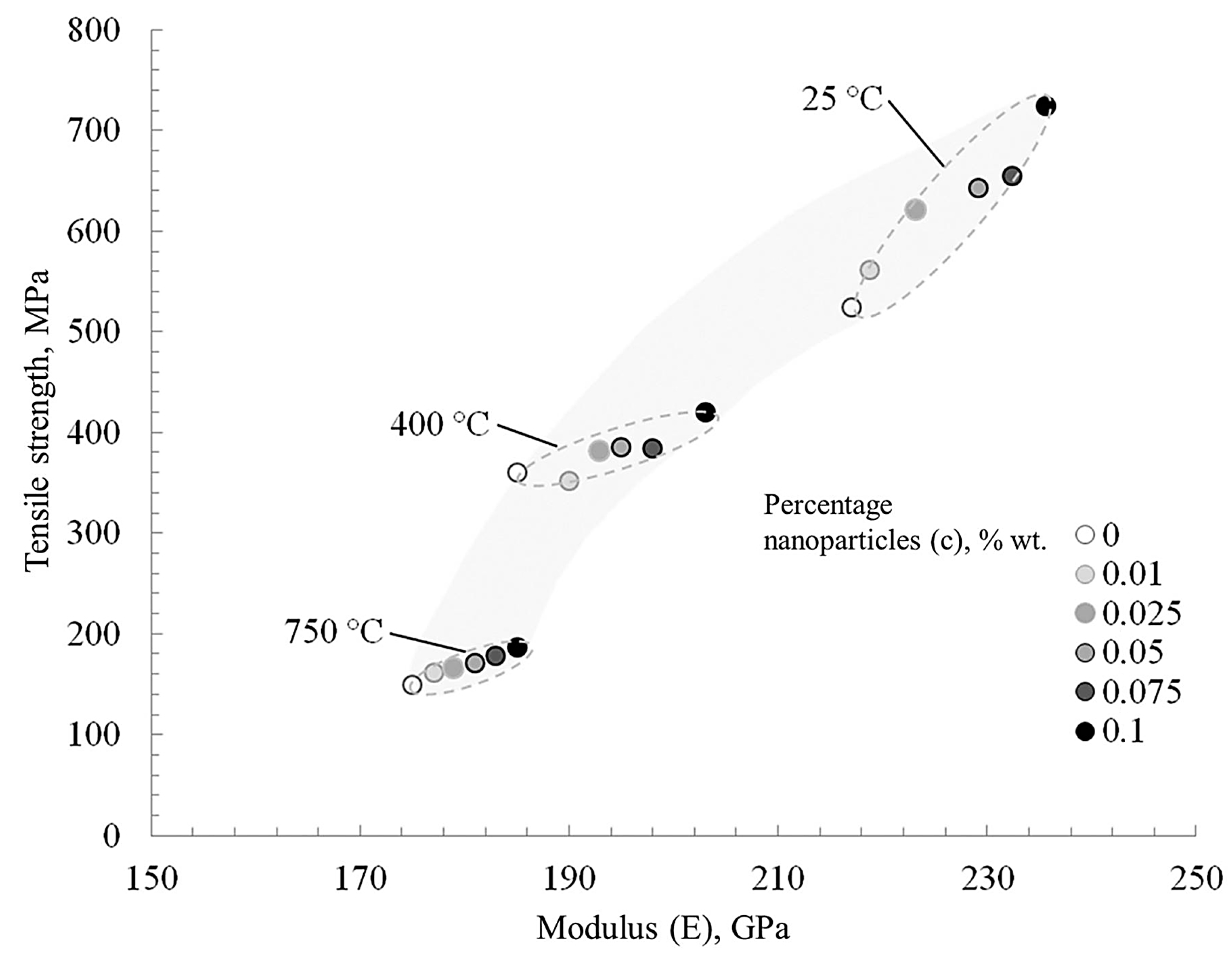
3.3. Tensile Strength
4. Discussion
5. Conclusions
Author Contributions
Funding
Institutional Review Board Statement
Informed Consent Statement
Data Availability Statement
Acknowledgments
Conflicts of Interest
References
- Huebner, E.U. (Ed.) Nickel Alloys; Marcel Dekker Inc.: New York, NY, USA; Basel, Switzerland, 2000; 180p. [Google Scholar]
- Goldshtein, M.I.; Litvinov, V.S.; Bronfin, M.F. Metallophysics of High-Strength Alloys; Metallurgia: Moscow, Russia, 1986; 312p. [Google Scholar]
- Davis, J.R. (Ed.) Nickel, Cobalt, and Their Alloys. ASM Speciality Handbook; ASM International: Materials Park, Novelty, OH, USA, 2000; 400p. [Google Scholar]
- Bruckart, W.L.; Jaffee, R.I. Cladding of molybdenum for service in air at elevated temperature. Trans. Am. Soc. Met. 1952, 44, 44. [Google Scholar]
- Lurie, S.; Volkov-Bogorodskiy, D.; Solyaev, Y.; Rizahanov, R.; Agureev, L. Multiscale modelling of aluminium-based metal-matrix composites with oxide nanoinclusions. Comput. Mater. Sci. 2016, 116, 62–73. [Google Scholar] [CrossRef]
- Kostikov, V.I.; Agureev, L.E.; Eremeeva, Z.V. Development of nanoparticle-reinforced alumocomposites for rocket-space engineering. Russ. J. Non Ferr. Met. 2015, 56, 325–328. [Google Scholar] [CrossRef]
- Sharma, A.; Roh, M.-H.; Jung, D.-H.; Jung, J.-P. Effect of ZrO2 Nanoparticles on the Microstructure of Al-Si-Cu Filler for Low-Temperature Al Brazing Applications. Met. Mater. Trans. A 2016, 47A, 510–521. [Google Scholar] [CrossRef]
- Chuvil’deev, V.N.; Kopylov, V.I.; Zeiger, W. A theory of non-equilibrium grain boundaries and its applications to nano- and micro-crystalline materials processed by ECAP. Ann. Chim. Sci. Des Matériaux 2002, 27, 55–64. [Google Scholar] [CrossRef]
- Ohji, T.; Hirano, T.; Nakahira, A.; Niihara, K. Particle/Matrix interface and its role in creep inhibition in alumina silicon carbide nanocomposites. J. Am. Ceram. Soc. 1996, 79, 33–45. [Google Scholar] [CrossRef]
- Grigorovich, V.K.; Sheftel’, E.N. Dispersion Hardening of Refractory Metals; Nauka: Moscow, Russia, 1980; 304p. [Google Scholar]
- Gottstein, G. Physical Foundations of Materials Science; Springer: Berlin, Germany, 2004; 502p. [Google Scholar]
- Thompson, A.W. Substructure strengthening mechanisms. Met. Trans. 1977, 8A, 833–842. [Google Scholar] [CrossRef]
- Lugovskoi, Y.F. Effect of structure on the fatigue strength of dispersion-hardened condensated based on copper II. Analysis of the first coefficient of the Mott—Stroh relation. Powder Met. Met. Ceram. 1998, 37, 432–437. [Google Scholar] [CrossRef]
- Taira, S.; Otani, R. Theory of High Temperature Strength of Materials; Metallurgiya: Мoscow, Russia, 1986; 280p. [Google Scholar]
- Springer Nature. Spark Plasma Sintering of Materials. Advances in Processing and Applications; Springer Nature: Cham, Switzerland, 2019; 767p. [Google Scholar]
- Borkar, T.; Banerjee, R. Influence of spark plasma sintering (SPS) processing parameters on microstructure and mechanical properties of nickel. Mater. Sci. Eng. A 2014, 618, 176–181. [Google Scholar] [CrossRef]
- Zhao, Y.; Topping, T.; Bingert, J.F.; Thornton, J.; Dangelewicz, A.; Li, Y.; Liu, W.; Zhu, Y.; Zhou, Y.; Lavernia, E. High Tensile Ductility and Strength in Bulk Nanostructured Nickel. Adv. Mater. 2008, 20, 3028–3033. [Google Scholar] [CrossRef]
- Naimi, F.; Minier, L.; Le Gallet, S.; Couque, H.; Bernard, F. Dense Nanostructured Nickel Produced by SPS from Mechanically Activated Powders: Enhancement of Mechanical Properties. J. Nanomater. 2013, 11. [Google Scholar] [CrossRef]
- Agureev, L.E.; Kostikov, V.I.; Yeremeyeva, Z.V.; Barmin, A.A.; Rizakhanov, R.N.; Ivanov, B.S.; Ashmarin, A.A.; Laptev, I.N.; Rudshteyn, R.I. Powder aluminum composites of Al–Cu system with micro-additions of oxide nanoparticles. Inorg. Mater. Appl. Res. 2016, 7, 507–510. [Google Scholar] [CrossRef]
- Mironov, V.V.; Agureev, L.E.; Eremeeva, Z.V.; Kostikov, V.I. Effect of Small Additions of Alumina Nanoparticles on the Strength Characteristics of an Aluminum Material. Dokl. Phys. Chem. 2018, 481, 110–113. [Google Scholar] [CrossRef]
- Lurie, S.; Belov, P.; Volkov-Bogorodsky, D.; Tuchkova, N. Interphase layer theory and application in the mechanics of composite materials. J. Mater. Sci. 2006, 41, 6693–6707. [Google Scholar] [CrossRef]
- Saunders, Z.; Noack, C.W.; Dzombak, D.A.; Lowry, G. Characterization of engineered alumina nanofibers and their colloidal properties in water. J. Nanoparticle Res. 2015, 17, 1–14. [Google Scholar] [CrossRef]
- Bravaya, N.M.; Galiullin, A.N.; Saratovskikh, S.L.; Panin, A.; Faingold, Е.; Vasilev, S.G.; Bubnova, M.; Volkov, V. Synthesis and properties of hybrid materials obtained by in situ copolymerization of ethylene and propylene in the presence of Al2O3 nanofibers (NAFEN™) on catalytic system rac-Et (2-MeInd) 2ZrMe2/isobutylalumoxane. J. Appl. Polym. Sci. 2016. [Google Scholar] [CrossRef]
- Panda, P.K.; Ramakrishna, S. Electrospinning of Alumina Nanofibers Using Different Precursors. J. Mater. Sci. 2007, 42, 2189–2193. [Google Scholar] [CrossRef]
- Yang, C.; Huang, H.-F.; de los Reyes, M.; Yan, L.; Zhou, X.-T.; Xia, T.; Zhang, D.-L. Microstructures and Tensile Properties of Ultrafine Grained Ni- (1-3.5) wt.% SiCNP Composites Prepared by a Powder Metallurgy Route. Acta Met. Sin. 2015, 28, 809–816. [Google Scholar] [CrossRef]
- Maweja, K.; Phasha, M.; Yamabe-Mitarai, Y. Alloying and microstructural changes in platinum–titanium milled and annealed powders. J. Alloy. Compd. 2012, 523, 167–175. [Google Scholar] [CrossRef]
- Rosenberg, S.J. Nickel and Its Alloys; National Bureau of Standards Monograph: Washington, DC, USA, 1968; 106p. [Google Scholar]
- Farraro, R.; McLellan, R.B. Temperature dependence of the Young’s modulus and shear modulus of pure nickel, platinum, and molybdenum. Metall. Trans. A 1977, 8, 1563–1565. [Google Scholar] [CrossRef]
- Engineering Properties of Nickel 200 and 201, Technical Bulletin T-15; Huntington Alloy Products Division, The International Nickel Co. Inc.: Paramus, NJ, USA, 1964.
- Nickel. Circular of the Bureau of Standarts. No. 100; Washington Government Printing Office: Washington, DC, USA, 1921; 105p.
- Bollmann, W. Electron-microscopic observations on the recrystallization of nickel. J. Inst. Met. 1959, 87, 439. [Google Scholar]
- Masatake, Y.; Motoyuki, S.; Hideo, K. Energetics of segregation and embrittling potency for non-transition elements in the Ni Σ5 (012) symmetrical tilt grain boundary: A first-principles study. J. Phys. Condens. Matter. 2004, 16, 3933. [Google Scholar] [CrossRef]
- Sanyal, S.; Waghmare, U.V.; Subramanian, P.R.; Gigliotti, M.F.X. Effect of dopants on grain boundary decohesion of Ni: A first-principles study. Appl. Phys. Lett. 2008, 93. [Google Scholar] [CrossRef]
- Young, G.; Najafabadi, R. Applications of Ab Initio Modeling to Materials Science: Grain Boundary Cohesion and Solid State Diffusion; No. LM-04K037; Lockheed Martin Corporation: Owego, NY, USA, 2004. [Google Scholar]
- Hanlon, T.; Kwon., Y.-N.; Suresh., S. Grain size effects on the fatigue response of nanocrystalline metals. Scr. Mater. 2003, 49, 675–680. [Google Scholar] [CrossRef]
- Ragulya, A.V.; Skorokhod, V.V. Consolidated Nanostructured Materials; Naukova dumka: Kiev, Ukraine, 2007; 369p. [Google Scholar]
- Ramakrishnan, P.; Tendolkar, G.S. Influence of thin oxide films on the mechanical properties of sintered metal-powder compacts. Powder Metall. 1964, 7, 34–49. [Google Scholar] [CrossRef]
- Bhattacharjee, P.P.; Sinha, S.K.; Upadhyaya, A. Effect of sintering temperature on grain boundary character distribution in pure nickel. Scr. Mater. 2007, 56, 13–16. [Google Scholar] [CrossRef]
- Minier, L.; Le Gallet, S.; Grin, J.; Bernard, F. A comparative study of nickel and alumina using spark plasma sintering (SPS). Mater. Chem. Phys. 2012, 134, 243–253. [Google Scholar] [CrossRef]
- Takagi, H.; Nishiyama, Y.; Sakamaki, K.; Yoshida, K. Microstructure and Hardness of Ni-NiO Composites Prepared by Powder Metallurgy. Trans. Jpn. Soc. Mech. Eng. Ser. A 1995, 6, 1933–1939. [Google Scholar] [CrossRef][Green Version]
- Fujimura, T.; Tanaka, S.-I. In-situ high temperature x-ray diffraction study of Ni/A12O3 interface reactions. Acta Mater. 1997, 45, 4917–4921. [Google Scholar] [CrossRef]
- Voicu, C.; Popa, F.; Marinca, T.F.; Neamţu, B.V.; Lostun, M.; Lupu, N.; Chicinaş, I. Synthesis and characterisation of Al2O3/Ni-type composites obtained by spark plasma sintering. Powder Metall. 2018. [Google Scholar] [CrossRef]
- Xie, G.; Ohashi, O.; Song, M.; Furuya, K.; Noda, T. Behavior of oxide film at the interface between particles in sintered Al powders by pulse electric-current sintering. Metall. Mater. Trans. A 2003, 34A, 699–703. [Google Scholar] [CrossRef]
- Nagae, T.; Yokota, M.; Nose, M.; Tomida, S.; Kamiya, T.; Saji, S. Effects of pulse current on an aluminum powder oxide layer during pulse current pressure sintering. Mater. Trans. 2002, 43, 1390–1397. [Google Scholar] [CrossRef]
- Dagan, G.; Shen, W.-M.; Tomkiewicz, M. Passivation of Permalloy Thin Films: II. In Situ Characterization of the Oxide Layer by Photoelectrochemical and Impedance Measurements. J. Electrochem. Soc. 1992, 139, 1855–1861. [Google Scholar] [CrossRef]
- Sikora, E.; Macdonald, D.D. Nature of the passive film on nickel. Electrochim. Acta 2002, 48, 69–77. [Google Scholar] [CrossRef]


Publisher’s Note: MDPI stays neutral with regard to jurisdictional claims in published maps and institutional affiliations. |
© 2021 by the authors. Licensee MDPI, Basel, Switzerland. This article is an open access article distributed under the terms and conditions of the Creative Commons Attribution (CC BY) license (http://creativecommons.org/licenses/by/4.0/).
Share and Cite
Agureev, L.; Kostikov, V.; Eremeeva, Z.; Savushkina, S.; Ivanov, B.; Khmelenin, D.; Belov, G.; Solyaev, Y. Influence of Alumina Nanofibers Sintered by the Spark Plasma Method on Nickel Mechanical Properties. Metals 2021, 11, 548. https://doi.org/10.3390/met11040548
Agureev L, Kostikov V, Eremeeva Z, Savushkina S, Ivanov B, Khmelenin D, Belov G, Solyaev Y. Influence of Alumina Nanofibers Sintered by the Spark Plasma Method on Nickel Mechanical Properties. Metals. 2021; 11(4):548. https://doi.org/10.3390/met11040548
Chicago/Turabian StyleAgureev, Leonid, Valeriy Kostikov, Zhanna Eremeeva, Svetlana Savushkina, Boris Ivanov, Dmitriy Khmelenin, Gleb Belov, and Yuri Solyaev. 2021. "Influence of Alumina Nanofibers Sintered by the Spark Plasma Method on Nickel Mechanical Properties" Metals 11, no. 4: 548. https://doi.org/10.3390/met11040548
APA StyleAgureev, L., Kostikov, V., Eremeeva, Z., Savushkina, S., Ivanov, B., Khmelenin, D., Belov, G., & Solyaev, Y. (2021). Influence of Alumina Nanofibers Sintered by the Spark Plasma Method on Nickel Mechanical Properties. Metals, 11(4), 548. https://doi.org/10.3390/met11040548