Article

Active Brazing of Alumina and Copper with Multicomponent Ag-Cu-Sn-Zr-Ti Filler

Department of Materials Science and Engineering, University of Seoul, 163, Seoulsiripdae-ro, Dongdaemun-gu, Seoul 02504, Korea
*
Author to whom correspondence should be addressed.
Metals 2021, 11(3), 509; https://doi.org/10.3390/met11030509
Submission received: 25 February 2021 / Revised: 9 March 2021 / Accepted: 16 March 2021 / Published: 19 March 2021

Abstract

:
The study was designed to investigate the synergic effect of Ti and Sn in the active metal brazing of Al2O3 ceramic to copper brazed, using the multicomponent Ag-Cu-Zr filler alloy. Numerous fine and hexagonal-shaped rod-like ternary intermetallic (Zr, Ti)5Sn3 phase (L/D = 5.1 ± 0.8, measured in microns) were found dispersed in the Ag-Cu matrix of Ag-18Cu-6Sn-3Zr-1Ti alloy, along with the ternary CuZrSn intermetallic phases. An approximate 15° reduction in contact angle and 3.1 °C reduction in melting point are observed upon the incorporation of Ti and Sn in Ag-18Cu-3Zr filler. Interestingly, the interface microstructure of Al2O3/Cu joints brazed by using Ag-18Cu-6Sn-3Zr-1Ti filler shows a double reaction layer: a discontinuous Ti-rich layer consisting of (Cu, Al)3(Ti, Zr)3O, TiO, and in-situ Cu-(Ti, Zr) precipitates on the Al2O3 side and continuous Zr-rich layer consisting of ZrO2 on the filler side. The shear strength achieved in Al2O3/Cu joints brazed with Ag-18Cu-6Sn-3Zr-1Ti filler is 31% higher, compared to the joints brazed with Ag-18Cu-6Sn-3Zr filler. Failure analysis reveals a composite fracture mode indicating a strong interface bonding in Al2O3/Ag-18Cu-6Sn-3Zr-1Ti filler/Cu joints. The findings will be helpful towards the development of high entropy brazing fillers in the future.

1. Introduction

Ceramics have a wide range of applications in electric vehicles, aerospace industries, nuclear and chemical-powder plant applications. Irrespective of their potential in various applications, utilizing ceramics in required complex shapes imposes serious manufacturing and economic limitations in industrial sectors [1,2,3,4,5]. The idea of ceramic to metal joining was considered as a promising approach that resolves the existing difficulties in the manufacturing process. Joining metals to ceramics provides complementary properties that cannot be achieved with either ceramics or metal alone; however, achieving a good joint interface between ceramic and metal has a lot of hurdles to overcome [2,3]. Moreover, the overall properties rely on the joint interface strength. Ceramics and metals have distinct differences in their bonding nature and chemical and physical properties. Metals have a metallic bond with free electrons; in contrast, ceramics have a covalent or ionic bond with extremely stable outer-shell electrons. Hence, molten metal does not wet the ceramic surface, thus limiting the prerequisite condition for joining, i.e., establishing intimate contact between ceramic and metal surface [4]. Additionally, distinct physical properties between ceramics and metals, such as elastic modulus, strength, and Coefficient of Thermal Expansion (CTE) mismatch lead to large residual stress during cooling, affecting the joint strength [5].
Adhesive bonding [6], diffusion bonding [7], active metal brazing (AMB) [8] and transient liquid-phase bonding [9] are some of the well-known ceramic-to-metal joining methods. Owing to its simplicity and good joint properties, AMB is the commonly employed ceramic–metal joining technique. AMB is a joining process wherein ceramic and metal surfaces sandwiched with Active Braze Alloy (ABA) are brazed in vacuum furnace. ABA generally consists of Ag, Cu, Ni or Au based fillers that contain Ti or Zr as active metals to promote their wetting on the ceramic surface in their molten state [10]. Moreover, in AMB there is no necessity to pre-coat the ceramic surfaces with molybdenum-manganese (Mo-Mn) metallizing layer, as the active metals in ABA improves the wetting and assist in the formation of reaction layer on the ceramic surface. Therefore, AMB is a suitable process for joining ceramic metal parts with complex shapes [10]. Commercially used ABAs are Ag-35.25Cu-1.75Ti wt.% (Cusil) and Ag-26.7Cu-4.5Ti wt.% (Ticusil), where Ti is distributed as Cu-Ti intermetallic compounds (IMCs) in the Ag-Cu eutectic alloy matrix [11]. Cu-Ti IMCs with a size range of 50–100 µm formed during solidification of Ag-Cu-Ti alloy deteriorate the mechanical property of the ceramic–metal brazing seam. To overcome this issue, Sn was added to promote the formation of finer Cu-Ti and Sn-Ti IMCs (<20 µm) [12]. Work of adhesion (Wad), defined as the amount of work required to separate two surfaces, is an important quantity associated with the bond strength of metal/ceramic interactions. Higher Wad in ceramic/metal system signifies a stronger bonding, which results in good joint strength. As an active element, Zr has higher work of adhesion (Wad) with Al2O3, compared to Ti [13]. In mid-1993, Scandia national laboratories came up with Zr based fillers such as Ag-28Cu-2Zr wt.% (Zrcusil) and Ag-1Cu-2Zr wt.% ABA alloy as alternative candidates for ceramic/metal joining [14]. Ag-Cu-Zr brazing fillers have been employed for joining various ceramics, such as Al2O3 [15], AlN [15], MoSi2 [16], cBN [17] and SiO2 [18]. However, their usage is limited by the formation of blocky Cu4AgZr IMC because of the high affinity of Zr with matrix elements Cu and Ag. Formation of Cu4AgZr IMC in the filler alloy also reduces the Zr availability for the formation of reaction layer, resulting in a thinner reaction layer [14]. Kim et al. [13] observed a reduced affinity of Zr with Cu and Ag upon the addition of Sn, thus reducing the fraction of Cu-Zr IMCs in the brazing seam. Additionally, the addition of Sn decreased the melting temperature of Ag-28Cu-5Zr wt.% filler and increased the shear strength of the Al2O3/Ni-Cr steel joints [19]. The shear strength increase upon Sn addition in Ag-Cu-Zr filler is mainly attributed to the reduction of blocky Cu4AgZr IMC [14,19]. Recently, double-active filler Ag-Cu-Zr-Ti is given attention, as it exhibits high hardness and wear resistance with appreciable wetting on cBN substrates. However, blocky Cu4AgZr IMCs in double-active filler Ag-Cu-Zr-Ti reduced the shear strength of brazed joints [20]. Considering the advantage of Sn in reducing the affinity of Cu-Zr IMC in Ag-Cu-Zr filler, the work reported here aims to study the interaction of Sn and Ti in Ag-Cu-Zr filler.
In the present era, multi-component alloys having more than three alloying elements, and high entropy alloys having five or more alloying elements wherein maximum and minimum atomic compositions for each elements ranges between 35 and 5 at.%, are widely explored in joining applications [21]. Different elements in multi-component alloys can interact and influence the reactions at the filler/ceramic interface. Hence, it important to understand the microstructure and the phase formation in the fillers. This study can be used to understand the IMCs formed during the interaction of elements Sn, Ti and Zr in the Ag-Cu system. In the present study, two multicomponent filler alloys, namely Ag-Cu-Sn-Zr and Ag-Cu-Sn-Zr-Ti, were studied for their microstructure, phase formation and contact angle on the Al2O3 substrate. Then, the interfacial microstructure and the corresponding shear strengths were investigated for Al2O3/Cu joints brazed by using Ag-Cu-Sn-Zr and Ag-Cu-Sn-Zr-Ti fillers.

2. Materials and Methods

2.1. Filler Alloy Fabrication and Active Metal Brazing

Braze filler alloys with nominal composition, as shown in Table 1, were prepared by using a vacuum furnace (all the alloy compositions mentioned in this work are in wt.%, unless stated otherwise). Commercially available powders of Ag (99.99%), Cu (99.99%), Sn (99.9%), Ti (99.95%) from Kojundo Chemical Laboratory Co., Ltd., (Saitama, Japan) and Zr powder (99.4%) from GG-JING YAN (Shaoguan, China) were used. The powders were mechanically mixed and melted at 1000 °C, in a vacuum furnace, at 1.3 × 10⁻² Pa. Vacuum melting is necessary to prevent the oxidation of filler alloys. The alloys were homogenized and re-melted at 1000 °C, to achieve compositional uniformity. From the ingot, the braze sheets were then cut, polished into sheet of dimension 15 mm × 15 mm × 0.3 mm and ultrasonically cleaned in ethanol.
Then, 96% pure Al2O3 (purchased from Korea electronic material, Gyeonggi, Korea), having a dimension of 15 mm × 15 mm × 5 mm, and 99.9% pure Cu (purchased from Daeduck metals, Gyeonggi, Korea) with a dimension of 20 mm × 20 mm × 5 mm were used as base ceramic and metal substrates respectively. These substrates were polished by using #500-, #800- and #1000-grit SiC abrasive paper and ultrasonically cleaned in ethanol. The as-prepared braze sheets were then sandwiched between Al2O3 and Cu substrates. AMB was performed at the vacuum level of 1.3 × 10⁻³ Pa with the heating and cooling rate of 10 and 5 °C/min, respectively. The peak brazing temperature and brazing time were fixed as 840 °C and 15 min, respectively, for both the brazing alloys.

2.2. Microstructural and Thermal Analysis

The brazed samples were cut perpendicular to the bonded interface, and metallographic specimens were prepared. Microstructures of the filler alloy and brazed joints were examined, using analytical SEM (JEOL JSM-6010PLUS, Tokyo, Japan) attached with an energy-dispersive spectrometer (EDS). The microstructure specimens were etched in a solution containing 25 mL H2O + 50 mL H2O2 + 25 mL ammonia water prior to the microstructural examination. The reaction phase at the Al2O3/filler interface was identified by XRD, using the Cu K-α spectrum having a wavelength of 1.5406 A (Bruker AXS GmbH-D8 DISCOVER, Karlsruhe, Germany). For XRD, the brazed samples were cut parallel to the bonded interface and polished until the reaction phases at the interface were revealed. The melting point of the filler alloys was analyzed, using differential scanning calorimetry (DSC, SDT 650, TA instruments, New castle, DE, USA) at a heating rate and cooling rate of 10 °C/min under N2 atmosphere. The sample weight was maintained at 10.5 ± 0.2 mg in all the DSC tests.

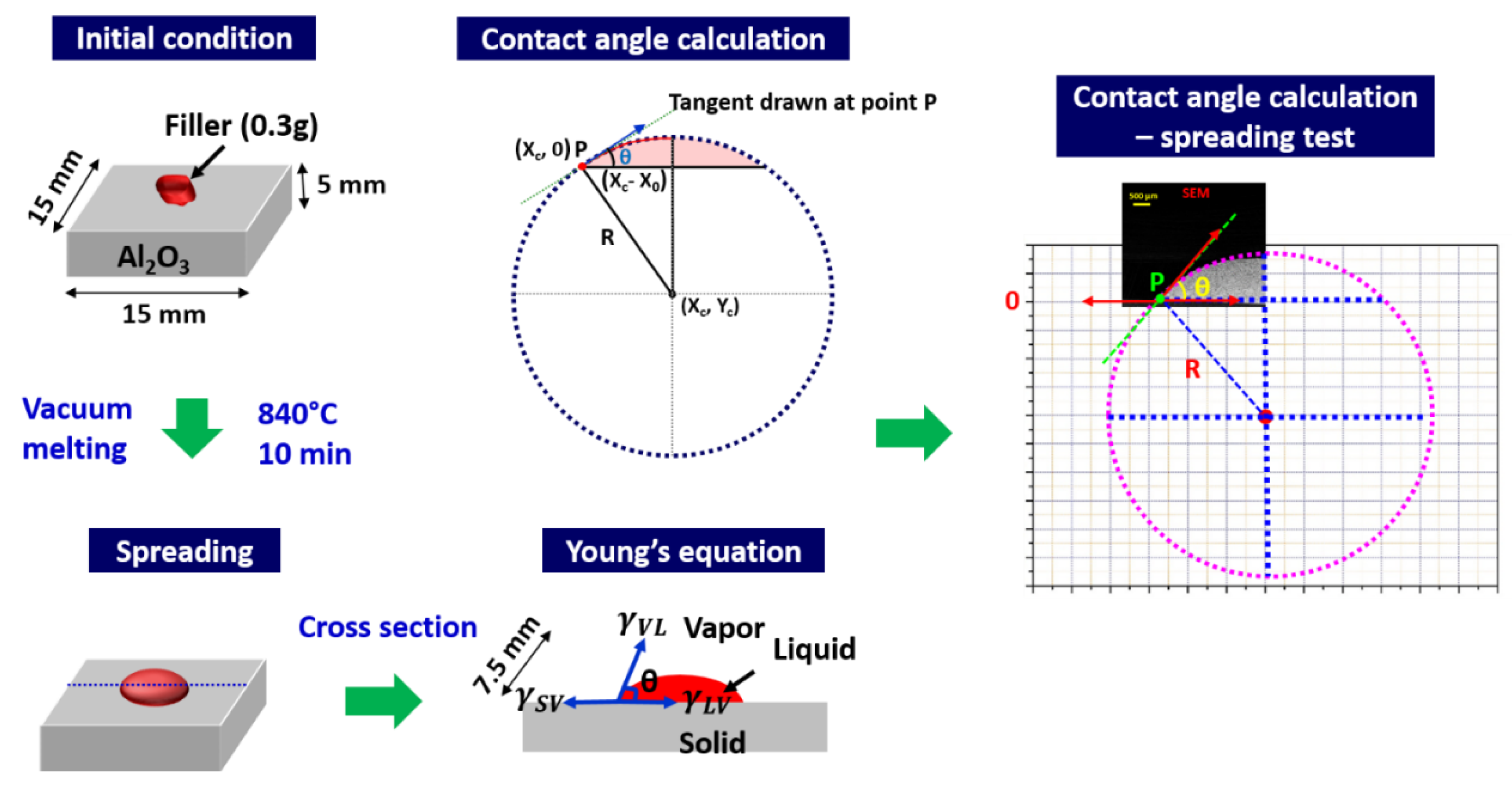
2.3. Contact Angle Measurement and Shear Test

The spreading tests for contact angle measurement were carried in accordance with the Japanese Industrial Standard (2003: JIS-Z-3198-3). To measure the contact angle, spreading of 0.3 g of filler alloy on Al2O3 substrate was carried in a vacuum furnace, at a vacuum level 1.3 × 10⁻³ Pa, with a heating and cooling rate of 10 and 5 °C/min, respectively. The temperature and time were 840 °C and 15 min, respectively. After spreading, the samples were mounted in epoxy, cut perpendicular to the spreading interface, and the contact angle is measured by following Young’s equation: [22]
γ SL =   γ SV γ LV cos θ
where γ SL , γ SV and γ LV represent the solid–liquid, solid–vapor and liquid–vapor surface tension, respectively, and θ represents the contact angle. The measurement procedure is schematically illustrated in Figure 1. Assuming the solidified solder having a spherical shape, a best fit circle for solder surface was drawn. A tangent was drawn at the point P, which is the intersection of the circle and the top surface of the Al2O3 substrate. The contact angle is then given by Equation (2) [23]:
θ   =   sin 1 ( R 2 y c 2 R )
where R is the radius of the circle and yc is the y-axis coordinate of center of the circle.
The reported contact angle measurement was the average of three specimens. The shear test was carried at a shear speed of 0.5 mm/min using UTM WDW-20 (Chenda tester, Jian, China). Each reported shear test value is an average value of three tested specimens. After the shear test, the fractured Al2O3 samples were mounted and sectioned to study the crack propagation.

3. Results and Discussion

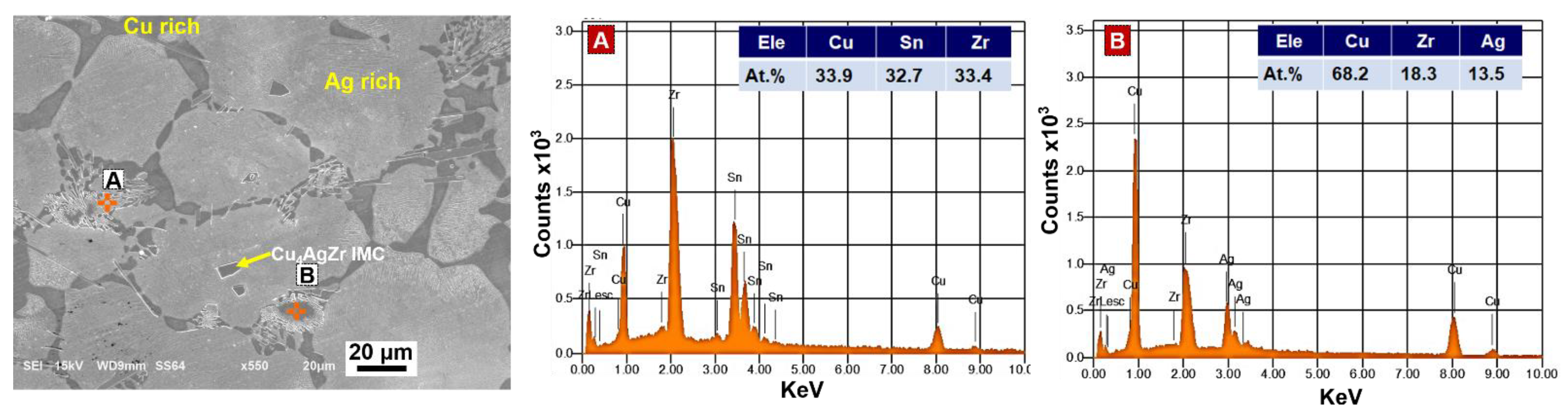
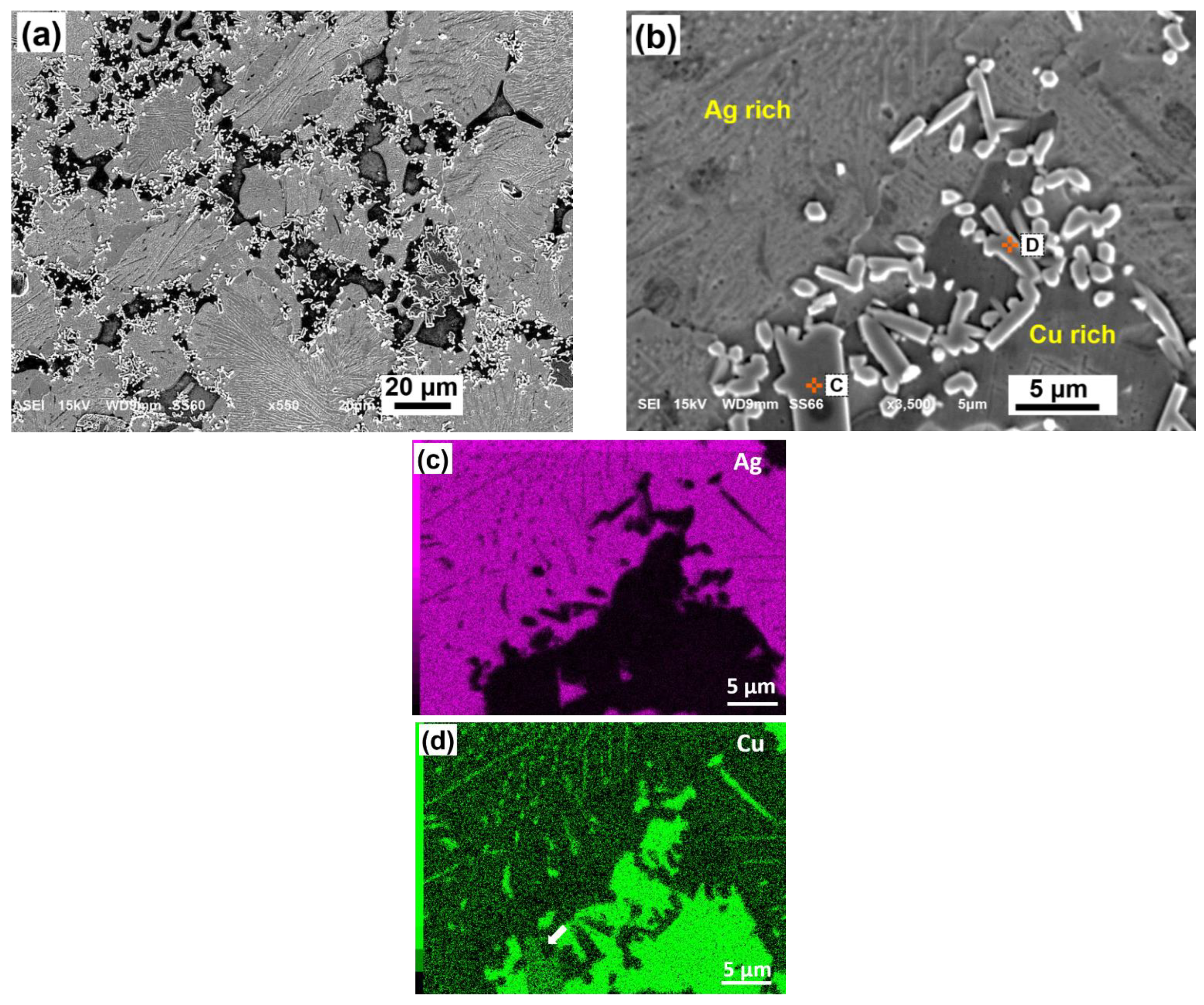
3.1. Microstructure of Ag-18Cu-6Sn-3Zr and Ag-18Cu-6Sn-3Zr-1Ti Brazing Filler

Figure 2 shows the microstructure and EDS analysis of as-cast filler alloys. The microstructure of the Ag-18Cu-6Sn-3Zr filler alloy as shown in Figure 2 consists of a bright Ag-rich and dark Cu-rich matrix region. It reveals a bright lamellar phase marked as A and dark blocky phase marked as B dispersed In the Ag-Cu matrix. EDS analysis on points A and B are shown in Figure 2. Based on the at.% calculations from the EDS analysis and the references listed in Table 2, the bright lamellar phase indicated by point A refers to the ternary CuZrSn phase [23] and the blocky phase indicated by point B refers to a ternary Cu4AgZr IMC [24].
Ag-Cu system is an interesting combination having the same crystal structure (face-centered cubic) and positive enthalpy of mixing (10.8 KJ·mol−1 [23]). During solidification, to attain equilibrium Cu and Ag atoms tend to segregate and forms Cu-rich and Ag-rich matrix [25]. As there are no thermodynamic investigations available for a quaternary Ag-Cu-Sn-Zr alloy, the present work characterizes the intermetallic phases based on the ternary systems of Ag-Cu-Zr [26,27,28] and Cu-Sn-Zr [24,29]. Zr has a maximum solid solubility of 0.1 at.% at 900 °C in Ag [26] and 0.12 at.% at 972 °C in Cu [27]. Liquid-phase separation is observed in the ternary Ag-Cu-Zr system in Ag-rich area, where the liquid melt (L) is separated into Ag-rich liquid (L1) and Cu-Zr-rich liquid (L2) [28]. During solidification, precipitation of Cu4AgZr IMC and occurs at 898 °C by the reaction (3). Cu4AgZr is a high-temperature IMC with a congruent melting temperature of 1080 °C [22].
L 1 ( Ag )   rich L 2 ( Cu - Zr )   rich   +   Cu 4 AgZr   +   α - Ag
Romaka et al. [29] experimentally investigated the isothermal section of the ternary Cu-Sn-Zr system at 397 and 497 °C. Apparently, from the investigation, a ternary equiatomic CuZrSn phase (designed as τ1) with TiNiSi structure type and cell parameters of a = 0.66279 nm, b = 0.43679 nm, c = 0.76791 nm has been identified. Yuan et al. [24] experimentally observed the presence of CuZrSn (τ1) phase in the Cu-Sn-Zr system at 700 °C. The atomic percentages of the CuZrSn (τ1) phase as reported by Romaka et al. [29] and Yuan et al. [24] is found to be good in agreement with the EDS in the present work as shown in Table 2. From the microstructure, the lamellar CuZrSn (τ1) phase either exists along with the Cu-rich inclusions or formed from Cu4AgZr IMC. The CuZrSn (τ1) phase could have transformed from the Sn-enriched Cu-Zr liquid (L2) during solidification. However, an in-depth analysis is required to understand the transformation mechanism.
Figure 3a–h shows the SEM microstructure, elemental mapping and EDS analysis of as-cast Ag-18Cu-6Sn-3Zr-1Ti filler alloy. Similar to Ag-18Cu-6Sn-3Zr filler, CuZrSn (τ1) phase (marked as C) is observed in Ag-18Cu-6Sn-3Zr1Ti filler as shown in Figure 3b. Since Ti and Zr are soluble over the entire composition range, presence of Ti in CuZrSn (τ1) phase is inevitable as seen from the EDS analysis of points C in Figure 3h. Blocky Cu4AgZr phase is not seen in Ag-18Cu-6Sn-3Zr-1Ti filler. Instead, a fine and hexagonal rod-like phase (L/D = 5.1 ± 0.8 measured in microns) was observed. EDS analysis indicated by point D confirms the presence of Ti, Zr and Sn in the rod-like phase. The at.% of the elements indicates that this phase is identical to (Zr, Ti)5Sn3 phase composition in the literature, as shown in Table 2 [30,31]. Elemental mapping of the magnified microstructure as shown in Figure 3c–g confirms the coexistence of Zr, Ti and Sn in (Zr, Ti)5Sn3 phase. Nowotny et al. reported that Zr5Sn3 and Ti5Sn3 IMCs can substitute Ti and Zr atoms to form a hexagonal (Zr, Ti)5Sn3 phase [31]. Several other researchers also support the formation of (Zr, Ti)5Sn3 phase in the Sn-Zr-Ti system over a wide range of Ti and Zr compositions [31,32,33]. Fine (Zr, Ti)5Sn3 phase formed upon the addition of Ti and Sn in Ag-Cu-Zr filler could be more beneficial in mechanical properties as compared to the blocky Cu4AgZr IMC in Ag-Cu-Zr and Ag-Cu-Zr-Ti fillers [22,34].
Table 2. Quantification of possible phases formed in Ag-18Cu-6Sn-3Zr and Ag-18Cu-6Sn-3Zr-1Ti alloy.
SpotNominal Composition from EDS (at.%)Nominal Composition from the Literature (at.%)Possible
Phase
Reference
AgCuSnZrTiAgCuSnZrTi
A-33.932.733.4--33.332.134.7-CuZrSn (τ1)[23]
B13.568.2-18.3-1864.4-17.6-Cu4AgZr[22]
C-33.730.928.27.2-33.332.134.7-CuZrSn (τ1)[23]
D--36.846.416.8--37.146.816.1(Zr, Ti)5Sn3[29,30,31,32]

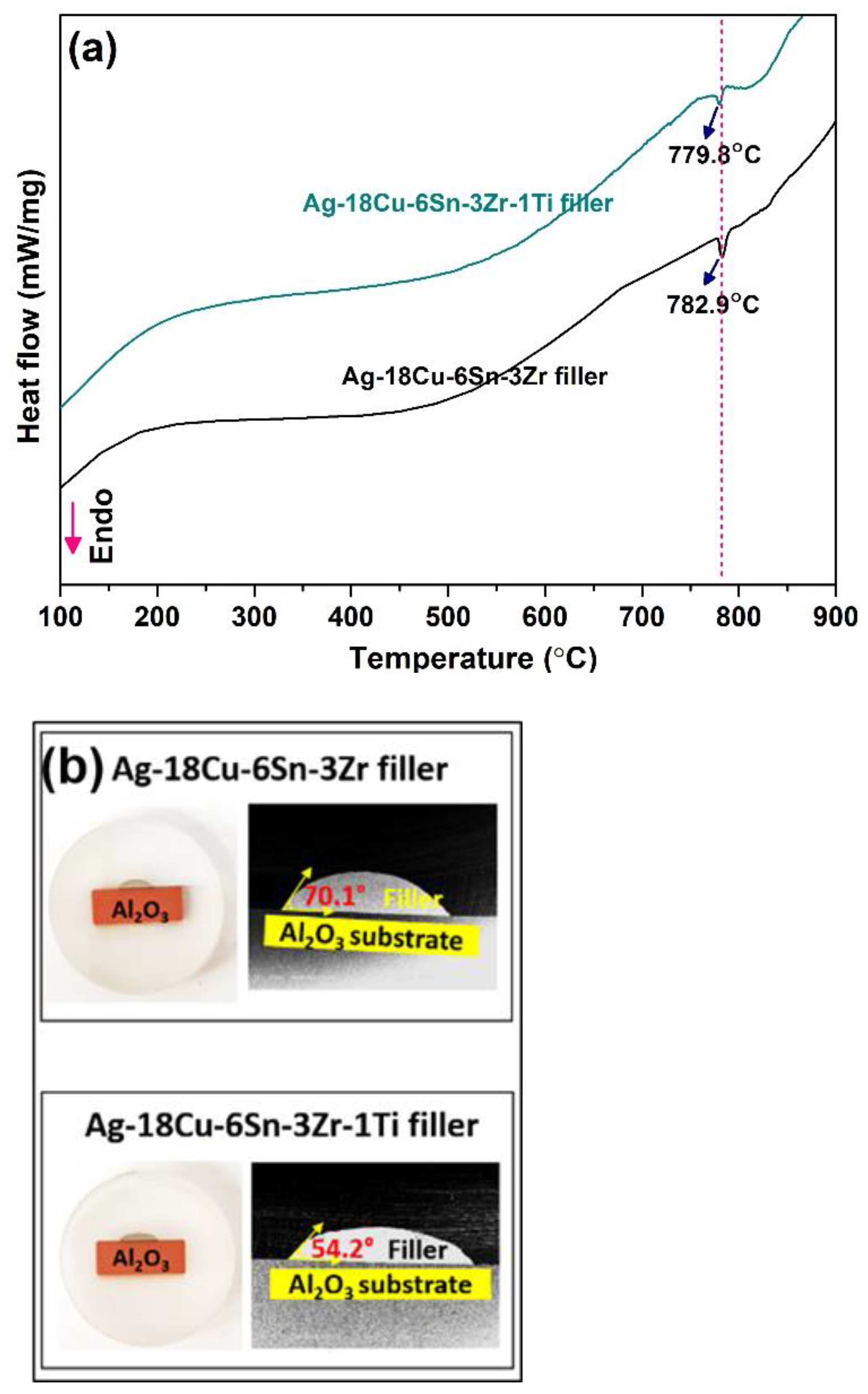
3.2. Thermal Analysis and Contact Angle of Ag-18Cu-6Sn-3Zr and Ag-18Cu-6Sn-3Zr-1Ti Filler on Al2O3 Substrate

Figure 4a represents the DSC curves for Ag-18Cu-6Sn-3Zr and Ag-18Cu-6Sn-3Zr-1Ti filler. One endothermic peak is observed in both the filler alloys. The peak melting temperature of Ag-18Cu-6Sn-3Zr filler is 782.9 °C slightly higher than the Ag-Cu eutectic melting temperature of 779 °C. Addition of 1 wt.% Ti in Ag-18Cu-6Sn-3Zr filler has slightly reduced the peak melting temperature to 779.8 °C. Reactive wetting and spreading are considered an important process in ceramic–metal brazing. Though distinctly defined, spreading and wetting are interrelated concepts and are often interpreted with a certain degree of ambiguity. Wetting is a necessary precursory condition required for spreading [35]. Landry proposed a model wherein the formation of a new compound at the interface leads to wetting in metal/ceramic systems. The final contact angle and spreading kinetics depend on the newly formed interfacial compound [36]. The lower contact angle is a consequence of a higher spreading rate and wettability. Brazing atmosphere has a substantial influence on the wettability of filler metal on the ceramic surface. Low oxygen potential in brazing atmosphere can prevent the active elements (Ti and Zr) in the filler from reacting with the oxygen, which may result in a loss in the wettability [22]. Figure 4b shows the contact angle of Ag-18Cu-6Sn-3Zr and Ag-18Cu-6Sn-3Zr-1Ti filler on the Al2O3 substrate, at 840 °C, for 15 min. A contact angle of 70.1 ± 0.4° was obtained for the Ag-18Cu-6Sn-3Zr filler. This value is considerably higher than the contact angle of 54.2 ± 0.5° observed for Ag-18Cu-6Sn-3Zr-1Ti filler. In metal–ceramic systems, the spreading rate is limited by the rate of interfacial reaction process namely: diffusive transport of reacting species and local reaction kinetics at the interface [36]. Although Ti and Zr are both active elements, low atomic mass and small atomic radius of Ti assist in rapid diffusion through the Ag-Cu alloy [17].
The activity coefficient is an important parameter that quantifies the activity (χTi) of titanium at the filler alloy and substrate interface during brazing and is given by Equations (4) and (5) [37]:
χ Ti =   γ Ti · X Ti
where XTi is the concentration of Ti and γ Ti is the activity coefficient described as follows [17].
ln γ Ti G i ¯ E RT
where G i ¯ E is the excess Gibbs free energy of mixing, R is the gas constant and T is the temperature. The higher the activity coefficient, the more there will be segregation of active elements at the ceramic–metal interface. The activity coefficient of Ti in infinitely diluted Cu-Ti alloy is −1.4 [38], whereas the activity coefficient of Zr in infinitely diluted Cu-Zr alloy is −4 [39]. Due to its high activity, Ti facilitates the formation of reaction products on the Al2O3 substrates at a faster rate, as compared to Zr. Consequently, the spreading enhances reducing the contact angle in Ag-18Cu-6Sn-3Zr-1Ti filler.

3.3. Interface Analysis of Al2O3/Cu Joint

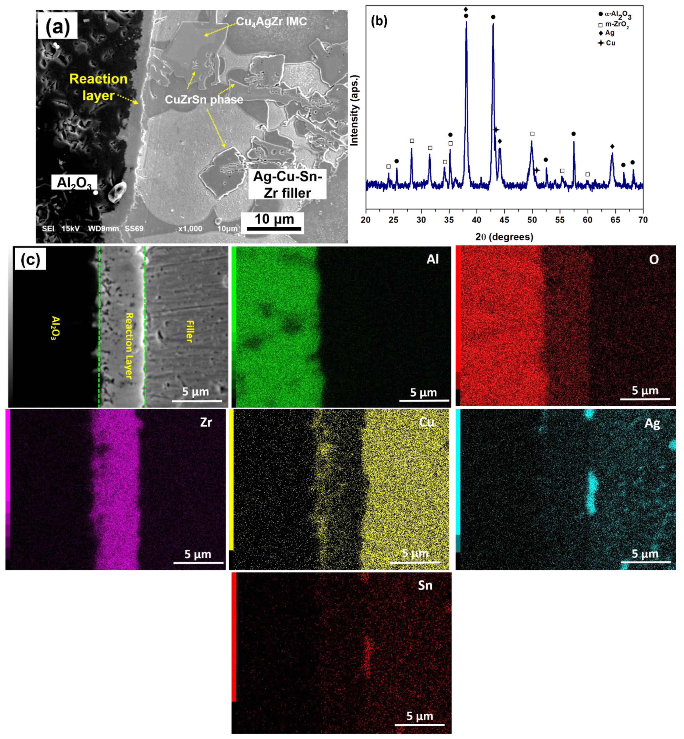
3.3.1. Interfacial Study of Cu/Al2O3 Joints Brazed with Ag-18Cu-6Sn-3Zr Filler

Figure 5 shows the characteristic features of Al2O3/Cu joint brazed with Ag-18Cu-6Sn-3Zr filler alloy. The chemical reactions between Al2O3 and Ag-18Cu-6Sn-3Zr filler resulted in a reaction layer with a thickness of 5.2 ± 0.4 µm at the Al2O3/Cu interface, as shown in Figure 5a. XRD analysis of reaction zone shown in Figure 5b displays the peaks corresponding to α-Al2O3, Ag, Cu and monoclinic ZrO2. Moreover, α-Al2O3 peak originates from the substrate, while Ag and Cu peaks originated from the filler alloy. EDS analysis of the interface for the individual elements Al, O, Zr, Cu, Ag and Sn in Figure 5c, shows the presence of Zr and O in the ZrO2 reaction layer. A copper-rich region is also observed in the immediate vicinity of the Al2O3 substrate ahead of ZrO2 layer. Formation of ZrO2 reaction layer at Al2O3/filler interface is considered as more complex when compared to a simple Al2O3 reduction-Zr oxidation reaction [15]. During brazing, Zr in the molten filler diffuses towards Al2O3 substrate, facilitates wetting and penetrates along the grain boundaries of Al2O3. Meanwhile, Al2O3 gets reduced to Al and O ions by Reaction (6) [40]:
Al 2 O 3 2 Al + 3 O
Zr in the molten filler reacts with O ions and gets oxidized to ZrO2 by Reaction (7):
Zr + 2 O ZrO 2
This leads to the oxidation-reduction reaction at the interface described below:
2 Al 2 O 3 + 3 Zr 3 Zr O 2 + 4 Al
However, Al2O3 is thermodynamically more stable than ZrO2 and the Gibbs free energy ( Δ G R 0 ) of Equation (8) is positive (396.8 kJ at 1127 °C) [15]. Loehman et al. proposed that the formation of Cu-Zr-Ag-Al precipitates on Al2O3 can lower the Gibbs free energy of Equation (7) and favors the formation of ZrO2 at the interface [15]. Therefore, after the filler metal is melted, Cu-Zr-rich liquid infiltrates along the Al2O3 grain boundaries and the high oxidation potential of Zr could have led to redox reaction within Al2O3. Thus, the ZrO2 reaction layer form and continue to grow by the outward diffusion of oxygen ions, leaving behind Cu at the Al2O/reaction layer interface to form Cu-rich precipitates [40]. Although a possible mechanism of ZrO2 formation is supported based on Equation (8), sufficient thermodynamic evidence on the formation of ZrO2 on Al2O3 is still too complex to comprehend.

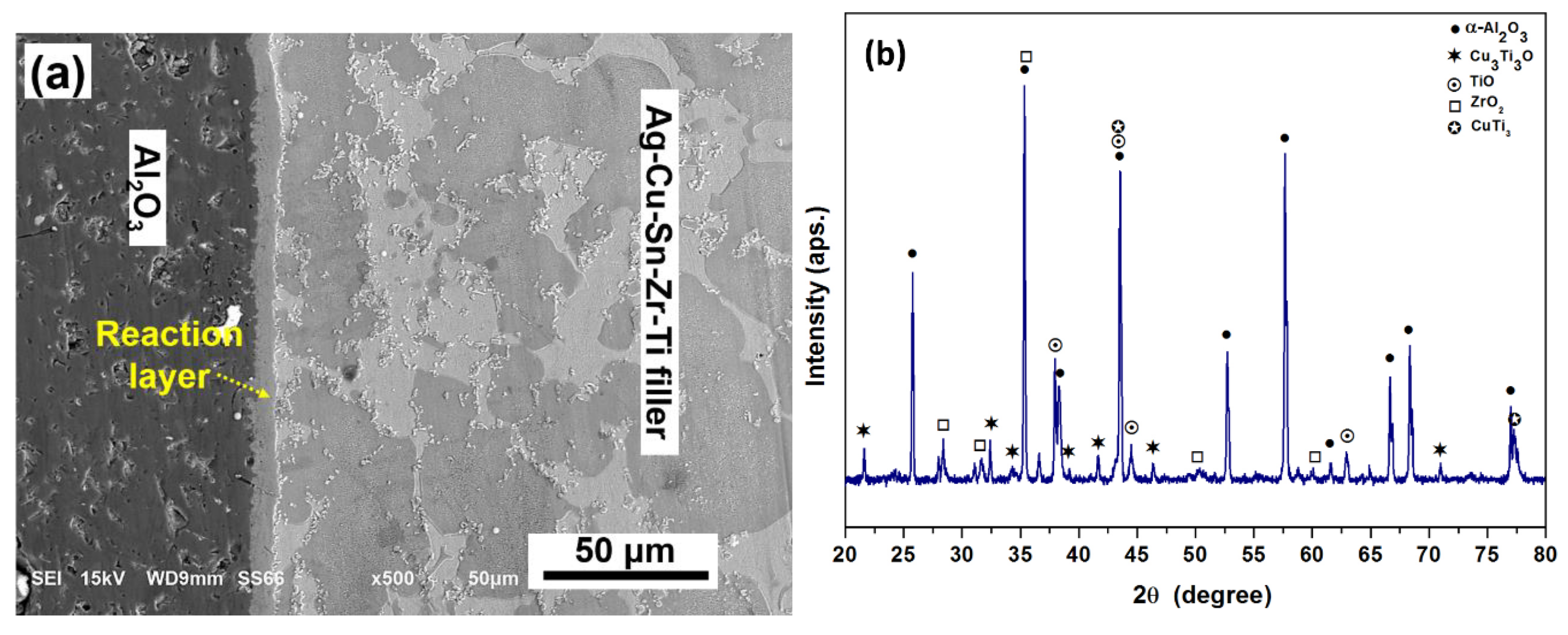
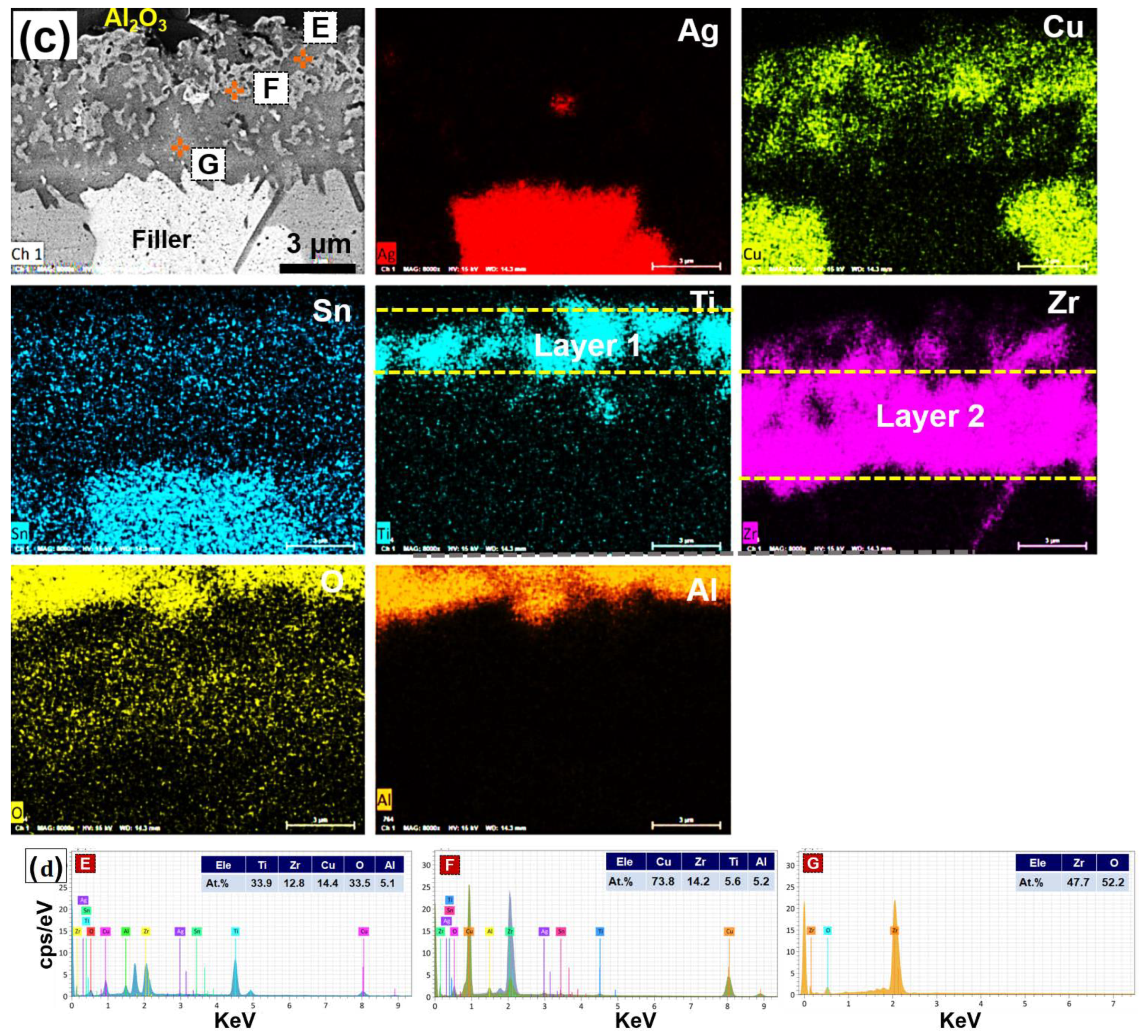
3.3.2. Interfacial Study of Cu/Al2O3 Joint Brazed with Ag-18Cu-6Sn-3Zr-1Ti Filler

Figure 6 shows the characteristic features of Al2O3/Cu joint brazed with Ag-18Cu-6Sn-3Zr-1Ti filler. The microstructure of the Al2O3/Cu joint, as shown in Figure 6a, displays a reaction layer of thickness 7.3 ± 0.3 µm at the interface. This is ~1.9 µm thicker, as compared to the reaction layer obtained by using Ag-18Cu-6Sn-3Zr filler. Furthermore, unlike the joints brazed by using Ag-18Cu-6Sn-3Zr filler, no blocky IMCs are found in the brazed seam. XRD analysis of the reaction layer shown in Figure 6b displays the peaks of α-Al2O3, Ag, Cu, Cu3Ti3O, CuTi3, TiO and m-ZrO2. High-magnification FESEM images and the elemental mapping, as shown in Figure 6c,d show two distinct composition of reaction layers (marked as I and II). A discontinuous Ti-rich region I is present immediately adjacent to Al2O3 substrate, followed by a continuous Zr-rich region II. Figure 6d displays the EDS analysis of the phases in the reaction layer of the magnified image. The atomic percentage of elements from EDS analysis corresponding to the spots E, F and G are given in Table 3. The stoichiometric ratio of elements Zr, Ti, Cu, Al and O in spot E corresponds to Cu3Ti3O, where Ti is substituted by Zr, and Cu is substituted by Al. During reduction of Al2O3, Al ions diffuses towards the filler and participates in the reaction products formed during the brazing. Earlier research also confirms the solubility of Al in (Cu, Al)3Ti3O compound [41]. The presence of elements Cu, Zr, Ti and Al in the EDS analysis of spot F and their stoichiometric composition matches with the Cu-(Ti, Zr) IMC with Al substituted in Cu. The EDS analysis in the spot G indicates the presence of Zr and O that coincides with the stoichiometric percentage of ZrO2. By combining EDS, XRD and elemental mapping analysis, it is found that the phases present in region I could be (Cu, Al)3(Zr, Ti)3O, TiO and in situ Cu-(Ti, Zr) IMC and the region II mainly composed of ZrO2.
As explained in Section 3.2, a high activity coefficient, low atomic mass and radius of Ti enable faster diffusion towards Al2O3 substrate, compared to Zr. Segregation of Ti results in the formation of Cu3Ti3O and TiO oxides in the immediate vicinity of Al2O3. Apparently, many works in the literature support the formation of interfacial reaction products, such as TiO2, TiO, Ti2O and Cu3Ti3O during the AMB between alumina and Ag-Cu-Ti brazing filler [37,42,43,44]. The established mechanism of reaction layer in Al2O3/Ag-Cu-Ti system is the formation of nm-thick TiO layer followed by µm-thick Ti3(Cu+Al)3O on Al2O3 [43]. However, the formation mechanism can be affected by the composition of the filler alloy and joining conditions. After melting, Ti in the filler metal diffuses and reacts with alumina to form TiO. Upon cooling, TiO reacts with Cu-Ti intermetallic compounds to form Cu3Ti3O and Ti2O as expressed by the Equations (9) and (10) [44]
Al 2 O 3 + 3 Ti 3 TiO + 2 Al
3 Cu 4 Ti + 2 TiO Ti 3 Cu 3 O + Ti 2 O + 9 Cu
As explained in Section 3.2, with low atomic mass and radius, Ti diffuses towards the Al2O3 at a faster rate, and the high activity coefficient of Ti facilitates the formation of reaction products, such as TiO and Cu3Ti3O, on the Al2O3 substrates. Hence, region I in the immediate vicinity of Al2O3 substrate is Ti-rich. However, it is complex to understand the formation mechanism of in situ Cu-(Ti, Zr) IMC. With higher atomic mass and radius, Zr diffuses towards the Al2O3 at a smaller rate and establish the formation of ZrO2 in region II. This results in the formation of double reaction layers at the interface.

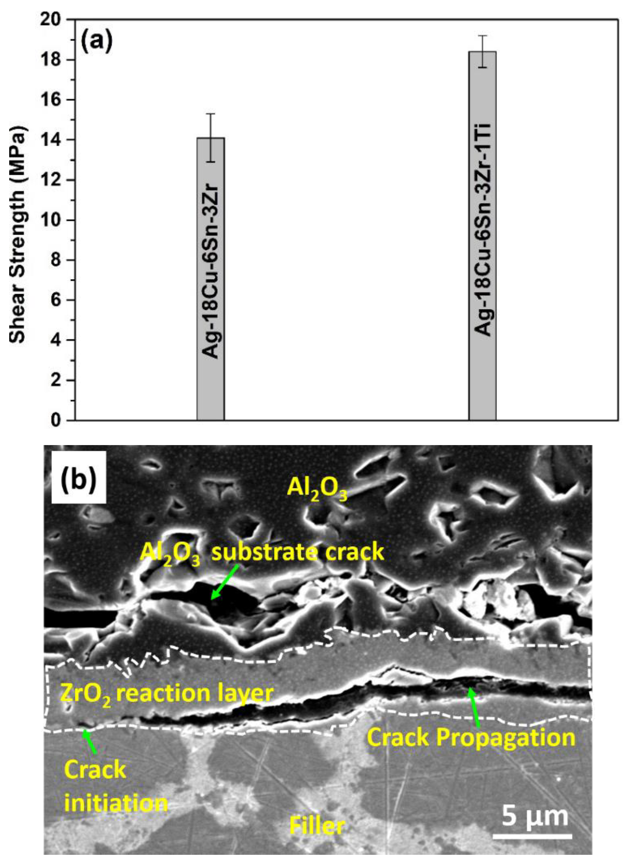
3.4. Effect of Ag-Cu-Sn-Zr-Ti Filler on the Shear Strength of Al2O3/Cu Joints

Figure 7a displays the shear strength of Al2O3/Cu joints brazed at 840 °C for 15 min, using Ag-Cu-Sn-Zr filler and Ag-Cu-Sn-Zr-Ti filler as a function of Zr content. The average shear strength of Al2O3/Cu joints brazed with Ag-18Cu-6Sn-3Zr-1Ti filler is higher (18.4 MPa), compared with Cu/Al2O3 joints brazed with Ag-18Cu-6Sn-3Zr filler (14.1 MPa). The reliability of the Al2O3/Cu joints depends on the residual stresses due to CTE and elastic modulus mismatch developed during cooling [5]. Crack propagation in the fractured Al2O3/Cu joints brazed with Ag-18Cu-6Sn-3Zr and Ag-18Cu-6Sn-3Zr-1Ti filler are shown in Figure 7b,c, respectively. In the specimens brazed with Ag-18Cu-6Sn-3Zr filler, cracks having initiated at the ZrO2 reaction layer/filler interface propagated through the ZrO2 layer, indicating a weak interface. Besides this, cracks are also seen in Al2O3 ceramic substrate adjacent to the reaction layer.
ZrO2 exhibits three polymorphs: monoclinic (m-ZrO2), tetragonal (t-ZrO2) and cubic (c-ZrO2). Moreover, m-ZrO2 is a stable structure at room temperature and pressure. During cooling in AMB, polymorphic transformation of t-ZrO2 to m-ZrO2 is accompanied by a volume increase of approximately 3%–5% [41]. As a consequence of volume change, residual stresses can be generated to this volume change and can result in micro-cracks formation in the m-ZrO2 reaction layer [5]. Therefore, the fracture toughness of m-ZrO2 becomes weak and is highly susceptible to crack propagation. Moreover, volume change and CTE mismatch can together generate large residual stresses that further weaken the Al2O3 ceramic substrate ahead of the reaction layer. Additionally, presence of blocky IMC in the filler must have created plastic strain localization at the IMC/matrix interface.
In the specimens brazed with Ag-18Cu-6Sn-3Zr-1Ti filler, the crack initiated at the ZrO2/filler interface, primarily propagated in ZrO2 reaction layer and then partially shifted towards the Al2O3 substrate. This composite fracture mode implies the existence of a strong bonding at the interface. The CTE values of Al2O3, ZrO2 and Ag-Cu filler are 8 × 10⁻⁶/°C [43], 10.5 × 10⁻⁶/°C [10] and (19.2–22) × 10−6/°C [43], respectively. At the Al2O3/Ag-18Cu-6Sn-3Zr-1Ti filler interface, the presence of the Ti-rich region consisting of Cu3Ti3O (15.2 × 10⁻⁶/°C [43]), TiO (9.1 × 10⁻⁶/°C [43]) oxides and Cu-(Ti, Zr) ahead of ZrO2 reaction layer may have alleviated the residual stresses and micro-cracks in m-ZrO2 reaction layer generated due to the CTE mismatch and t-ZrO2 to m-ZrO2 transformation, respectively. Additionally, in situ formed Cu-(Ti, Zr) IMC dispersed in the oxide reaction layer can block the crack propagation in the reaction layer. This results in a strong interface with high fracture toughness. Thus, multicomponent Ag-Cu-Sn-Zr-Ti filler has shown potential to explore the possibilities of upgrading the existing commercial fillers to join a wide range of ceramics and metals.

4. Conclusions

Al2O3/Cu joint was successfully brazed at 840 °C, for 15 min, using multicomponent Ag-Cu-Sn-Zr and Ag-Cu-Sn-Zr-Ti fillers. The results can enhance the understanding of elements interaction in the multi-component fillers, as well as their interaction in ceramic/metal interface. Conclusions are drawn as follows:
  • The microstructure of Ag-Cu-Sn-Zr filler consists of CuSnZr ternary phase and blocky Cu4AgZr IMC in the Ag-Cu matrix, whereas the microstructure of Ag-Cu-Sn-Zr-Ti filler consists of CuSnZr ternary phase and micron-sized ternary (Zr, Ti)5Sn3 IMC dispersed in the Ag-Cu matrix.
  • The peak melting temperature of Ag-18Cu-6Sn-3Zr is 782.9 °C, which is 3.1 °C higher than Ag-18Cu-6Sn-3Zr-1Ti filler. The contact angle of Ag-18Cu-6Sn-3Zr-1Ti filler is 15° lower compared to Ag-18Cu-6Sn-3Zr filler. The presence of Ti in Ag-18Cu-6Sn-3Zr filler proved to enhance the spreading.
  • Al2O3/Cu joint brazed by using Ag-18Cu-6Sn-3Zr-1Ti filler at 840 °C for 15 min produced a Ti-rich region on the Al2O3 side, followed by m-ZrO2 reaction layer on the filler side (Al2O3/Ti-rich region consisting of Cu3Ti3O, TiO and Cu-(Zr, Ti) /m-ZrO2/filler/Cu), whereas the Ag-18Cu-6Sn-3Zr filler resulted in a typical m-ZrO2 reaction layer.
  • Al2O3/Cu joints brazed by using Ag-18Cu-6Sn-3Zr-1Ti filler exhibits a higher shear strength and stronger bonding interface, as compared to Al2O3/Cu joints brazed by using Ag-18Cu-6Sn-3Zr filler. The presence of the Ti-rich region reduces the residual stress build-up on Al2O3 substrate and presence of consisting of Cu3Ti3O, in situ Cu-(Ti, Zr) IMC dispersed in reaction layer enhances the fracture toughness of m-ZrO2 reaction layer.

Author Contributions

S.H.R. and S.J.H. conceived, designed and performed the experiments; S.H.R. analyzed the data and wrote the paper. J.P.J. project funding and supervision. All authors have read and agreed to the published version of the manuscript.

Funding

This work was supported by the Technology development program (No. S2903245), funded by the Ministry of Small and Medium Enterprises (SMEs) and Startups, of the Korea.

Data Availability Statement

The data is available from the corresponding author upon request.

Conflicts of Interest

The authors declare no conflict of interest.

References

  1. Tomsia, A. Ceramic/metal joining for structures and materials. Le J. Phys. IV 1993, 3, C7-1317–C7-1326. [Google Scholar] [CrossRef]
  2. Peteves, S.D. Joining nitride ceramics. Ceram. Int. 1996, 22, 527–533. [Google Scholar] [CrossRef]
  3. Ferne, J.A.; Drew, R.A.L.; Knowles, K.M. Joining of engineering ceramics. Int. Mater. Rev. 2009, 54, 283–331. [Google Scholar] [CrossRef]
  4. Uday, M.B.; Ahmad-Fauzi, M.N.; Noor, A.M.; Rajoo, S. Current issues and the problems in the joining of ceramic to metal. In Joining Technologies; Ishak, M., Ed.; IntechOpen: London, UK, 2016; Volume 8, pp. 159–193. [Google Scholar]
  5. Jasim, K.M.; Hashim, F.A.; Yousif, R.H.; Rawlings, R.D.; Boccaccini, A.R. Actively brazed alumina to alumina joints using CuTi, CuZr and eutectic AgCuTi filler alloys. Ceram. Int. 2010, 36, 2287–2295. [Google Scholar] [CrossRef]
  6. Halbig, M.C.; Asthana, R.; Singh, M. Diffusion bonding of SiC fiber-bonded ceramics using Ti/Mo and Ti/Cu interlayers. Ceram. Int. 2015, 41, 2140–2149. [Google Scholar] [CrossRef]
  7. Wang, M.C.; Tao, X.; Xu, X.Q.; Miao, R.; Du, H.; Liu, J.; Guo, A. High-temperature bonding performance of modified heat-resistant adhesive for ceramic connection. J. Alloys Compd. 2016, 663, 82–85. [Google Scholar] [CrossRef]
  8. Hanson, W.B.; Ironside, K.I.; Fernie, J.A. Active metal brazing of zirconia. Acta Mater. 2000, 48, 4673–4676. [Google Scholar] [CrossRef]
  9. Lan, L.; Yu, J.B.; Yang, Z.; Li, C.; Ren, Z.; Wang, Q. Interfacial microstructure and mechanical characterization of silicon nitride/nickel-base super alloy joints by partial transient liquid phase bonding. Ceram. Int. 2016, 42, 1633–1639. [Google Scholar] [CrossRef]
  10. Wang, N.; Wang, D.P.; Yang, Z.W.; Wang, Y. Interfacial microstructure and mechanical properties of zirconia ceramic and niobium joints vacuum brazed with two Ag-based active filler metals. Ceram. Int. 2016, 42, 12815–12824. [Google Scholar] [CrossRef]
  11. Ali, M.; Knowles, K.M.; Mallinson, P.M.; Fernie, J.A. Interfacial reactions between sapphire and Ag-Cu-Ti based active braze alloys. Acta Mater. 2016, 103, 859–869. [Google Scholar] [CrossRef] [Green Version]
  12. Kishimoto, T.; Kashiwagi, K.; Sakaguchi, O. Active Metal Brazing Material. U.S. Patent US9375811B2, 28 June 2016. [Google Scholar]
  13. Kim, J.H.; Yoo, Y.C. Bonding of alumina to metals with Ag-Cu-Zr brazing alloy. J. Mater. Sci. Lett. 1997, 16, 1212–1215. [Google Scholar] [CrossRef]
  14. Stephens, J.J.; Hosking, F.M.; Walker, C.A.; Dudley, E.C.; Yost, F.G. The evolution of ternary Ag-Cu-Zr active braze filler metal for Kovar/Alumina braze joints. In Proceedings of the 3rd International Brazing and Soldering Conference, San Antonio, TX, USA, 24–26 April 2006; pp. 207–213. [Google Scholar]
  15. Loehman, R.E.; Tomsia, A.P. Reactions of Ti and Zr with AlN and Al2O3. Acta. Met. Mater. 1992, 40, 75–83. [Google Scholar] [CrossRef]
  16. Ramsheh, H.H.; Sani, M.A.F.; Kokabi, A.H. Microstructure and mechanical properties of MoSi2-MoSi2 joints brazed by Ag-Cu-Zr interlayer. Mater. Des. 2013, 49, 197–202. [Google Scholar] [CrossRef]
  17. Simhan, D.R.; Mukhopadhyay, P.; Ghosh, A. On segregation of Zr and wettability of active Ag-Cu-Zr alloy on cubic boron nitride surface. Mater. Lett. 2017, 207, 183–186. [Google Scholar] [CrossRef]
  18. Song, Y.Y.; Li, H.L.; Zhao, H.Y.; Liu, D.; Song, X.G.; Feng, J.C. Interfacial microstructure and mechanical property of brazed copper/SiO2 ceramic joint. Vacuum 2017, 141, 116–123. [Google Scholar] [CrossRef]
  19. Yoo, Y.C.; Kim, J.H.; Park, K. Microstructure and bond strength of Ni-Cr steel/Al2O3 joints brazed with Ag-Cu-Zr alloys containing Sn or Al. Mater. Sci. Technol. 1999, 15, 1331–1334. [Google Scholar] [CrossRef]
  20. Simhan, D.R.; Ghosh, A. Vacuum brazing of cubic boron nitride to medium carbon steel with Zr added passive and Ti activated eutectic Ag-Cu alloys. Ceram. Int. 2018, 44, 4891–4899. [Google Scholar] [CrossRef]
  21. Park, S.W.; Lee, H.; Lee, B.H.; Kim, T.H.; Kim, K.I.; Hong, S.A.; Kim, M.; Hyun, S.K.; Ryu, G.H.; Kim, K.T. Effect of Interface Microstructure on Joint Strength of Zirconia/Titanium Alloy Brazed with Amorphous Zr-Ti-Ni-Cu Active Filler Metal. Metals 2020, 10, 718. [Google Scholar] [CrossRef]
  22. Akselsen, O.M. Review: Advances in brazing of ceramics. J. Mater. Sci. 1992, 27, 1989–2000. [Google Scholar] [CrossRef]
  23. Kang, D.H.; Jung, I.H. Critical thermodynamic evaluation and optimization ofAg-Zr, Cu-Zr and Ag-Cu-Zr systems and its application to amorphous Cu-Zr-Ag alloys. Intermetallics 2010, 18, 815–833. [Google Scholar] [CrossRef]
  24. Yuan, G.; Luo, W.; Ouyang, Y.; Liang, J. The Isothermal Section of the Zr-Sn-Cu Ternary System at 700 °C. J. Phase Equilibria Diffus. 2018, 39, 196–203. [Google Scholar] [CrossRef]
  25. Niyomsoan, S.; Gargarella, P.; Chomsaeng, N.; Termsuksawad, P.; Kühn, U.; Eckert, J. Phase Separation in Rapid Solidified Ag-rich Ag-Cu-Zr Alloys. Mater. Res. 2015, 18, 120–126. [Google Scholar] [CrossRef]
  26. Karakaya, I.; Thompson, W.T. The Ag-Zr (Silver-Zirconium) System. J. Phase Equilibria 1992, 13, 143–146. [Google Scholar] [CrossRef]
  27. Wu, X.; Wang, R.; Peng, C.; Feng, Y.; Cai, Z. Effects of annealing on microstructure and mechanical properties of rapidly solidified Cu-3 wt% Ag-1 wt% Zr. Mater. Sci. Eng. A 2019, 739, 357–366. [Google Scholar] [CrossRef]
  28. Janovszky, D.; Tomolya, K.; Sycheva, A.; Kaptay, G. Stable miscibility gap in liquid Cu-Zr-Ag ternary alloy. J. Alloys Compd. 2012, 541, 353–358. [Google Scholar] [CrossRef]
  29. Romaka, L.; Koblyuk, N.; Stadnyk, Y.V.; Frankevych, D.; Skolozdra, R. Phase Equilibria in the Zr-Cu-Sn System and Crystal Structure of ZrCuSn and ZrCuSn2. Pol. J. Chem. 1998, 72, 1154–1159. [Google Scholar]
  30. Nowotny, H.; Auer-Welsbach, H.; Buiss, J.; Kohl, A. Ein Beitrag zur Mn5Si3-Struktur (D 88-Typ). Mon. Chem. 1959, 90, 15–23. [Google Scholar] [CrossRef]
  31. Zhan, Y.; Guo, Q.; Zhang, G.; Hu, Z.; Zhang, X.; Hu, J. Isothermal section of the Ti–Zr–Sn ternary system at 473 K. J. Alloys Compd. 2019, 485, 170–173. [Google Scholar] [CrossRef]
  32. Arico, S.F.; Gribaudo, L.M. The Sn-Ti-Zr system: Equilibrium phases at 900 °C. J. Nucl. Mater. 2001, 288, 217–221. [Google Scholar] [CrossRef]
  33. Saltykov, V.A.; Meleshevich, K.A.; Samelyuk, A.V.; Verbytska, O.M.; Bulanova, M.V. Isothermal section at 1400 °C of the Ti–Zr–Sn system. J. Alloys Compd. 2008, 459, 348–353. [Google Scholar] [CrossRef]
  34. Xiao, D.H.; Li, X.X.; Zhang, F.Q.; Zhang, Y.S. Effect of Zr addition on microstructure and properties of Ag-Cu-Ti alloys. J. Mater. Eng. Perform 2014, 23, 1854–1860. [Google Scholar] [CrossRef]
  35. Hosking, M.; Yost, F.G. The Mechanics of Solder Alloy Wetting and Spreading, 1st ed.; Springer: New York, NY, USA, 1994. [Google Scholar]
  36. Landry, K.; Eustathopoulos, N. Dynamics of wetting in reactive metal/ceramic systems: Linear spreading. Acta Mater. 1996, 44, 3923–3932. [Google Scholar] [CrossRef]
  37. Hirnyj, S.; Indacochea, J.E. Phase transformations in Ag70.5Cu26.5Ti3 filler alloy during brazing processes. Chem. Met. Alloys 2008, 1, 323–332. [Google Scholar] [CrossRef]
  38. Katayamaa, I.; Tanigawa, S.; Živković, D.; Hattori, Y.; Yamashita, H. Newly developed EMF cell with zirconia solid electrolyte for measurement of low oxygen potentials in liquid Cu-Cr and Cu-Zr alloys. J. Min. Met. Sect. B Met. 2012, 48, 331–337. [Google Scholar] [CrossRef]
  39. Vlad, M. Thermodynamic assessment of the Cu—Ti system in micro alloyed copper base alloys. In The Annals of “Dunarea de Jos”; University of Galati Fascicle ix Metallurgy and Materials Science: Galati, Romania, 2006; Volume 2, pp. 53–57. ISSN 1453–083X.N. [Google Scholar]
  40. Yoo, Y.C.; Kim, J.H.; Park, K. Microstructural characterization of Al2O3/AISI 8650 steel joint brazed with Ag–Cu–Sn–Zr alloy. Mater. Lett. 2000, 42, 362–366. [Google Scholar] [CrossRef]
  41. Kelkar, G.P.; Carim, A.H. Al solubility in M6X compounds in the Ti-Cu-O system. Mater. Lett. 1995, 23, 231–235. [Google Scholar] [CrossRef]
  42. Stephens, J.J.; Hosking, F.M.; Headley, T.J.; Halva, P.F.; Host, F.G. Reaction layers and mechanisms for a Ti- activated braze on sapphire. Met. Mater. Trans. A 2003, 34, 2963–2972. [Google Scholar] [CrossRef]
  43. Kassam, T.A.; Babu, N.H.; Ludford, N.; Yan, S.; Howkins, A. Secondary Phase Interaction at Interfaces of High-Strength Brazed Joints made using Liquid Phase Sintered Alumina Ceramics and Ag-Cu-Ti Braze alloys. Sci. Rep. 2018, 8, 3352. [Google Scholar] [CrossRef] [PubMed] [Green Version]
  44. Lin, K.L.; Singh, M.; Asthana, R. Interfacial characterization of alumina to alumina joints fabricated using silver-copper-titanium interlayers. Mater. Charact. 2014, 90, 40–51. [Google Scholar] [CrossRef]
Figure 1. Schematic illustration of contact angle measurement after spreading.
Metals 11 00509 g001
Figure 2. Microstructure of as-cast Ag-18Cu-6Sn-3Zr filler with EDS analysis of spots A and B.
Metals 11 00509 g002
Figure 3. (a) Microstructure of Ag-18Cu-6Sn-3Zr-1Ti brazing filler; (b) magnified microstructure (cg) elemental mapping corresponding to (b), displaying Ag, Cu, Sn, Ti and Zr, respectively; and (h) EDS analysis of spot C and D in (b).
Metals 11 00509 g003aMetals 11 00509 g003b
Figure 4. (a) DSC curve; (b) contact angle of Ag-18Cu-6Sn-3Zr and Ag-18Cu-6Sn-3Zr-1Ti brazing filler on Al2O3 substrate.
Metals 11 00509 g004
Figure 5. Al2O3/Cu joints brazed using Ag-18Cu-6Sn-3Zr filler: (a) interface microstructure, (b) XRD pattern of reaction zone adjacent to Al2O3 and (c) elemental mapping of brazed Al2O3/Ag-18Cu-6Sn-3Zr interface.
Metals 11 00509 g005
Figure 6. Al2O3/Cu joints brazed by using Ag-18Cu-6Sn-3Zr-1Ti filler: (a) interface microstructure; (b) XRD pattern of reaction zone adjacent to Al2O3; (c) elemental mapping of brazed Al2O3/Ag-18Cu-6Sn-3Zr-1Ti interface elements Ag, Cu, Sn, Ti, Zr, O and Al; (d) and EDS analysis of spot E, F and G.
Metals 11 00509 g006aMetals 11 00509 g006b
Figure 7. (a) Effect of brazing filler on the shear strength of Al2O3/Cu joints; (b,c) fracture analysis of Al2O3/Cu joints brazed, using Ag-18Cu-6Sn-3Zr and Ag-18Cu-6Sn-3Zr-1Ti, respectively.
Metals 11 00509 g007aMetals 11 00509 g007b
Table 1. Nominal composition of the brazing filler alloy.
S. No.Composition in Weight %
AgCuSnZrTi
1.731863-
2.7218631
Table 3. Average elemental composition of reaction products in Figure 6c.
SpotNominal Composition from EDS (at.%)Possible Phase
CuTiZrAlO
E14.433.912.85.133.5(Cu, Al)3(Ti, Zr)3O oxide
F73.85.614.25.2-Cu-(Ti, Zr)
G--47.7-52.2ZrO2 oxide
Publisher’s Note: MDPI stays neutral with regard to jurisdictional claims in published maps and institutional affiliations.

