Abstract
Abrasive waterjet cutting is a well-established non-conventional technique for the processing of difficult-to-cut material and rendering of various complex geometries with high accuracy. However, as in every machining process, it is also required that high efficiency and productivity are achieved. For that reason, in the present study, the effect of performing the machining process by multiple passes is investigated, and the evaluation of this approach is performed in terms of total depth of penetration, kerf width, kerf taper angle, mean material removal rate, and cutting efficiency. In the case of multiple passes, the passes are performed in the same direction with the traverse speed adjusted accordingly in order to maintain the total machining time constant in each case. From the experimental results, it was found that the effect of multiple passes on the kerf characteristics, mean material removal rate, and cutting efficiency depends on the process conditions, especially regarding the depth of penetration, and it is possible to achieve significantly higher efficiency by the multi-pass cutting technique when the appropriate process conditions are selected.
1. Introduction
The machining of hard-to-cut materials has always been considered a challenge, as the achievement of contradicting goals such as high efficiency and productivity on the one side and low cost and power consumption on the other side requires carefully selected process conditions based both on experience and thorough understanding of the physics of the processes involved. Whereas usually conventional machining processes were primarily selected in industrial practice until the last few decades, non-conventional techniques such as laser machining, Electrodischarge Machining (EDM), and Abrasive Waterjet (AWJ) cutting are becoming increasingly popular due to their unique advantages and especially their ability to efficiently machine difficult-to-cut materials such as the ones frequently used in automotive and aerospace industries [1].
AWJ cutting is a unique and modern technology that allows the cutting of a large variety of complex shapes and a wide range of material types. Moreover, unlike other non-conventional processes, it does not involve increased temperatures, and thus, AWJ cutting can be considered as a cold cutting process [2]. The accuracy of the parts made by this technology depends mainly on the selection of cutting parameters shaping the cutting ability of a high-pressure abrasive stream. In general, this machining method is used to cut through materials; however, the researchers are also trying to establish the conditions to control the depth of cut by controlling four main parameters, namely the jet pressure (P), abrasive mass flow rate (ma), traverse speed (vt), and the stand-off distance (h) [1,3,4]. This process is known as AWJ Milling (AWJM) and relies on controlling a uniform depth of Cut (DoC) in order to render features such as slots or pockets, among others. Several researchers have studied the influence of main process parameters on the process outcome during AWJM. Goutham et al. [5] attempted to establish a monitoring system for AWJ milling using acoustic emissions and cutting forces during the controlled depth cutting of pockets. Their findings indicated that the depth of cut and the Material Removal Rate (MRR) during AWJ milling increase as the jet pressure increases and decrease as vt and h increases. Husin et al. [6] investigated the effect of all the main process parameters during AWJ of stainless steel workpieces and revealed that the kerf width was primarily affected by the standoff distance, while the slot depth was primarily affected by the traverse rate and waterjet pressure; low waterjet pressure, traverse speed, and standoff distance led to an improved surface quality of the slots.
Yuvaraj and Pradeep Kumar [7,8] performed experiments on the AWJ machining of AISI D2 steel workpieces with different abrasive mesh sizes and different jet impingement angles. They found that the optimum result during the AWJ cutting was achieved by setting the jet angle at 70°, jet pressure at 225 MPa, and by using the #100 abrasive mesh size. Kulisz et al. [9] investigated the effect of various parameters on surface roughness indicators; from their results, the traverse speed was proven to be a decisive factor toward the regulation of surface roughness, whereas other parameters such as the abrasive mass flow rate were less significant. Hlavacova et al. [10] conducted an interesting study, aiming to determine whether the different microstructures and heat treatment processes of the steel specimens can lead to variations on their surface quality during AWJ cutting. From the experimental results analysis, the carbon content of steel and the homogeneity of the microstructure were identified as the most important parameters affecting the machinability and surface quality of the workpieces.
Apart from the studies aiming to correlate process parameters with the process outcome, other studies attempt to propose methods that can improve the efficiency of the AWJ cutting. One of the techniques employed for the increase of efficiency is the use of multiple passes for the material removal instead of a single machining pass. In the relevant literature, there are a few studies concerning multi-pass AWJ cutting, which will be briefly discussed afterwards. It is to be noted that studies involving the processing of workpieces by AWJM with multiple passes in the horizontal direction, such as the studies involving the creation of pockets with overlapping paths [11,12], will not be discussed in this work.
Hashish [13] performed a comprehensive study on machining techniques relevant to AWJ cutting and was among the first to suggest the possibility of multi-pass AWJ cutting. Experiments of single-pass milling were performed on aluminum, titanium, and Inconel, and a multi-pass experiment was also conducted on glass and graphite composites, among other materials. The results revealed that when the traverse feed rate is higher, the smoothest cut can be produced but, as it is decreased, the Material Removal Rate (MRR) yields to the maximum. Another parameter that affects the MRR and the surface finish is the garnet size, with the finer particle size producing a finer surface, but at the same time reducing the MRR. Regarding Ti-6Al-4V, Fowler et al. [14] studied the effects of the traverse feed rate, the abrasive grit size, and the number of passes on the Material Removal Rate (MRR) during AWJ cutting. The results indicate that the surface waviness increases significantly with the number of passes with a lower traverse feed rate. On the other hand, the MRR becomes lower as the traverse speed increases. The scientific team led by Wang [15,16,17,18,19] carried out a series of experimental studies on multi-pass milling of alumina ceramics in order to find the optimal cutting conditions and determine the efficiency of this approach. The results of their experiments showed that the use of multi-pass cutting can generally improve the technological performance compared to single-pass milling. Additionally, it has been proven that combining the multi-pass technique and cutting head oscillation cutting technique can lead to an increase of the depth of cut by 50.8% on average compared to a single pass cut without oscillation under the same machining conditions.
Boud et al. [20] conducted AWJ experiments at a various number of passes and found out that MRR was reduced at higher number of passes, which was probably due to the larger residual compressive stresses that were required to be overcome. Doreswamy et al. [21] showed that the kerf width was increased at multi-pass AWJ cutting but the difference between the top and bottom width was reduced. Srinivasu et al. [22] observed that the total depth of cut during multi-pass AWJ cutting was lower than expected and attributed this phenomenon to the increased standoff distance. Miao et al. (2018) [23] conducted an optimization study on multi-pass cutting of AISI 304 stainless steel by AWJ machining. The multi-pass technique was proven to be able to improve the surface quality of the cross-section and the kerf taper. The cross-sections of a multi-pass deepening-cutting process were shown to present large and also deep erosion pits in the lower layer. For this reason, the researchers proposed a “trimming” method that consists of two different stages of material removal, with the first one being related to cutting off the workpiece and subsequently “trimming” the workpiece to a greater extent. Thus, the cross-section after four trimming passes was improved, and the striation lines were almost invisible, with the smooth region almost extending across the whole cross-section. Xiao et al. [24] conducted experiments relevant to the AWJ machining of composites and investigated the efficiency of multi-pass AWJM. It was found that multipass AWJM was beneficial regarding the reduction of kerf taper and increase of quality, but for that reason, it was required to adjust the process conditions such as jet pressure and traverse speed at subsequent passes. An efficient AWJM for near-net-shape operations of complex geometries related to multiple passes was presented by Uhlmann, Männel, and Braun [25]. In this study, a strategy involving the superposition of two different kerfs cut from two different ends of the workpiece was introduced, and it was applied in order to achieve a variable kerf depth and render sculptured surfaces, such as turbine blades.
It becomes evident from the literature review that a comprehensive study on multi-pass AWJ cutting, taking into consideration the variation of several process parameters such as jet-pressure, traverse speed, abrasive mass flow rate, and the number of passes, is not yet conducted. Thus, in the present study, the effect of multiple passes on the depth of cut, kerf width, kerf taper angle, Material Removal Rate, and cutting efficiency during the AWJ milling of steel workpieces under various process conditions is investigated. During the experiments, the total processing time is kept constant by varying the traverse feed accordingly in order to determine whether the multi-pass AWJ cutting is more efficient than single-pass AWJ cutting and under which conditions.
2. Materials and Methods
In the present study, multi-pass AWJ milling experiments are conducted under varying process conditions with a view to determine whether the use of multiple passes can affect the kerf characteristics considerably and whether it is more advantageous in terms of process efficiency or not. The workpiece material is a commercial chromium molybdenum-vanadium (60CrMoV18-5) steel alloy, which is commercially known as CALMAX by its manufacturer and is suitable for plastic and cold work applications. It is characterized by high toughness and good wear resistance, dimension stability, and weldability with the chemical composition given in Table 1 and a hardness value of 220 HV.

Table 1.
Chemical composition of workpiece material (%w/v).
The AWJ Milling experiments were performed on an H.G. RIDDER—Automatisierungs GmbH model HWE-1520 machine (H.G. RIDDER H., Hamm, Germany). Specifically, 20 experiments were employed with four levels of traverse speed (vt) and numbers of milling passes and three levels of abrasive mass flow (ma) and jet pressure (P) at a constant standoff distance (h). The following Table 2 presents the selected value range, which is wide enough in respect to the restrictions of the equipment used, allowing for significantly different results in each case, whereas the combinations of process parameters for each experiment are summarized in Table 3, along with the experimental results. In each experiment, a non-through straight slot of 50 mm length was created by the action of the high pressure waterjet with garnet abrasive particles. The traverse speed and number of passes are varied accordingly in order to keep the total machining time constant; e.g., for a fourfold increase of number of passes, the traverse speed increases also by four times. Thus, the efficiency of using multiple passes for the same machining time can be determined. In cases where multiple passes are performed, the direction of the waterjet is the same for each pass. For each experiment, the jet impingement angle was 90°, the employed abrasive was garnet with mesh size #80, while the water jet nozzle diameter was 0.3 mm, and the AWJ concentration tube diameter was 1 mm. The workpiece material dimensions were 50 mm × 200 mm × 20 mm, and the slots on the tool steel were cut across the entire length of the material (50 mm). Before the actual abrasive waterjet tests were carried out, preliminary tests under conditions similar to some of the actual tests took place in order to assess the repeatability of results regarding the kerf dimensions obtained in each case. These preliminary tests indicated that there was an insignificant variation of the results for the three repeated tests of the same experimental conditions; thus, it was not required that all the experiments should be conducted multiple times. The following Figure 1 shows the schematic of the basic geometric characteristics of the AWJ milling setup along with a SEM image of the garnet abrasive particles.
Table 2.
Process parameters and their levels.
Table 3.
Experimental conditions and results.
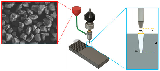
Figure 1.
Schematic of the Abrasive Waterjet (AWJ) milling setup showing an SEM image of the garnet particles and the basic geometric characteristics of the slots.
To measure the slot dimensions, a VHX-6000 ultra-deep-field microscope (KEYENCE, Mechelen, Belgium) was used, which is based on Focus Variation Microscopy (FVM), equipped with a 20–2000× objective. This technique is similar to confocal microscopy, and the measuring method of an FV microscope is based on a white light LED source that, before it reaches the measuring surface, passes through a semi-transparent mirror and a lens. Then, the reflected light from the focused areas returns through the lens, and a beam splitter directs it onto a photonic detector, which registers the geometric and photometric information. In other words, FV can deliver colorful high-resolution 3D surface measurements by merging the small depth of a classical optical system and vertical scanning. After the experiments were conducted, the kerf width and depth were measured from 2D images, and the 3D slot surface was generated based on the above-mentioned technique. It is to be noted that given the variability of the slot dimensions along the slot, measurements were conducted on three different representative cross-sections in order to obtain a more accurate view of the kerf dimensions. The same procedure was followed also for the determination of the cross-section area, which is required in order to estimate the MRR; for the calculation of the cross-section area, the average value of three characteristic cross-sections, namely the three cross-sections where the kerf dimensions were measured, was calculated. Figure 2 shows the AWJH.G. RIDDER—Automatisierungs GmbH model HWE-1520 machine and the 3D Keyence profilometer (Hamm, Germany).
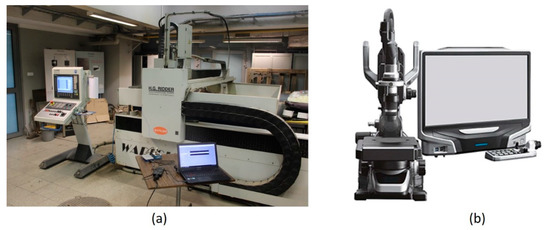
Figure 2.
(a) H.G. RIDDER AWJ center model HWE-1520 and (b) Keyence 3D optical microscope.
3. Results
3.1. Experimental Results and Slot Morphology
After the experiments were conducted, the depth of penetration (denoted with d), top kerf width (denoted with wt), and kerf taper angle (denoted with a) were measured by analyzing the images obtained by the microscope. These results are summarized in Table 3.
From the results of Table 3, it can be seen at first that a variation exists in terms of depth of penetration, top kerf width, and kerf taper angle values in most cases with a varying number of passes and different process conditions. This variation is directly reflected on the morphology of produced slots, as it can be observed that on some occasions, deep and narrow slots are produced, whereas other slots are shallow and wider. Figure 3 shows representative images from the measurements of the slots’ width and depth by utilizing a digital microscope with an embodied profilometer.
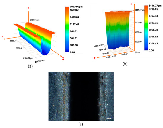
Figure 3.
Slots dimension measurements by using a digital microscope for (a) a 3D image 3rd experimental slot, (b) a 3D image of the 12th slot, and (c) top view of the 16th experiment.
As it can be seen from the calculated standard deviation values (denoted in Table 3 with σ and a subscript indicating the quantity for which the standard deviation was calculated) for each of the measured quantities, the deviation of each of the measurements obtained for the same experimental conditions was relatively low, and in every case, it is lower than 5% of the average value of the measured quantities. Given these relatively low deviation values, in the rest of the manuscript, only the average values of each quantity are discussed.
Generally, the shallower slots with a depth to width ratio close to 1 are those produced under milder process conditions, and as the abrasive mass flow rate and waterjet pressure values increase, the incision profile of the slots becomes steeper, with the ratio reaching values as low as 0.1 in the last experimental case. This is also confirmed by the calculation of the kerf taper angle in Table 3 where, as it will be further explained in Section 3.3, it can be observed that the kerf taper angle becomes lower for higher abrasive mass flow rates and waterjet pressure values, indicating a steeper profile toward the lower surface of the slot.
3.2. Dependence of Depth of Penetration on the Number of Passes
Regarding the dependence of depth of penetration values on the number of passes, different behaviors are observed for different process conditions. From the results of Table 3 and Figure 4, it can be seen that at the lowest abrasive mass flow rate and waterjet pressure values, the creation of a slot with a higher number of passes (denoted as n) at the same total machining time leads to lower total depth of penetration until eight passes are used, where an increased value of depth is obtained. However, this value does not exceed the value obtained with a single machining pass. A different behavior is observed at higher abrasive mass flow rate values, where the total depth of penetration value is constantly increasing for higher numbers of passes until eight passes are used, where the depth of penetration value becomes smaller than the previous ones but higher than the value obtained with a single machining pass. Finally, in cases with higher waterjet pressure, the increase of the number of passes leads finally to a considerably higher depth of penetration value, between 1.5 to almost 2 times higher than the value obtained at a single pass. This clear diversity of behaviors observed regarding the depth of penetration obtained with different number of passes under various process conditions can be attributed to the difference in the relevant intensity of the waterjet beam energy.
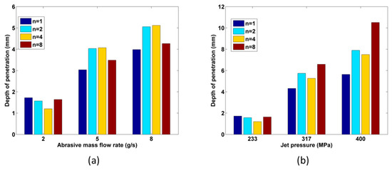
Figure 4.
Variation of the depth of penetration for increasing number of passes in respect to (a) abrasive mass flow rate and (b) jet pressure.
In the cases with relatively low values of abrasive mass flow rate and waterjet pressure, the energy of the waterjet is not sufficient to overcome the resistance of the workpiece material when larger traverse feeds and multiple passes are selected; thus, the total depth of penetration remains either close to the one obtained at a single pass with a low traverse rate or even lower. As it was pointed out by Boud et al. [20], the residual compressive stresses induced in the workpiece material from the previous passes pose an additional difficulty in the material removal process of the subsequent passes. Moreover, the increase of the real standoff distance as the number of passes is increased leads to reduced energy of the waterjet beam and the material removal process is less effective [22,26]. Nevertheless, at higher abrasive mass flow rates, it seems that the increased momentum of the abrasive waterjet is sufficient in order to overcome the material resistance, even at harsher conditions up to a point. Finally, at both high abrasive mass flow rates and jet pressure values, a higher total depth of cut can be obtained at a higher number of passes with the same total cutting time, as it was also observed in previous works [26,27]. Generally, as it can be seen in Figure 5 in most cases, the total depth of penetration obtained at a higher number of passes (denoted as di, where I = number of passes) is higher than the one obtained at a single pass (denoted as d1), implying that although a clear increasing trend does not exist in every case in respect to the number of passes, it is possible to achieve higher depths when a higher number of passes at higher traverse speeds are selected. Consequently, in these cases, considerably lower time is required to machine the same amount of material than in the respective cases conducted with a single machining pass.
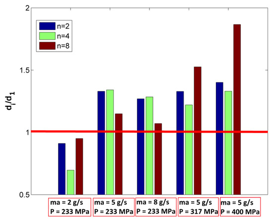
Figure 5.
Ratio of total depth of penetration for multi-pass cases to depth of penetration achieved by a single pass under various process conditions.
After the dependence of depth of penetration on the number of passes is discussed and explained, the effect of process conditions on the depth of penetration will be also analyzed. From Figure 6a, it can be seen that in any case, the results observed in the relevant literature are confirmed, as an increase of the abrasive mass flow rate within the selected value range leads clearly to an increase of the depth of penetration in every case. The same conclusion can be drawn in respect to the waterjet pressure, as it can be seen from Figure 6b that an increase of waterjet pressure leads to higher depth of penetration values, which is something that is anticipated from the findings in the relevant literature.
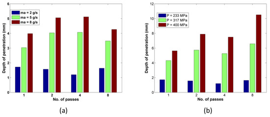
Figure 6.
Variation of depth of penetration for cases with different number of passes under different (a) abrasive mass flow rate values and (b) jet pressure values.
3.3. Dependence of the Kerf Width and Kerf Taper Angle on the Number of Passes
Regarding the dependence of the kerf width on the number of passes, the variation of top kerf width values for cases with different number of passes and traverse speed values is depicted in Figure 7a,b. From these figures, it can be deduced that the top kerf width is affected to a different degree from the increase in machining passes under different process conditions. However, the general trend observed in these results is a slight increase of top kerf width values when the number of passes increases for cases with the same total machining time [21]. In some cases, there are some extreme deviations, leading to top kerf width values over 1.25–1.3 mm, but generally, the top kerf width values do not differ very much. Contrary to the case of depth of penetration, the values of top kerf width do not vary considerably under different process conditions. This can be explained due to the fact that the abrasive mass flow rate and waterjet pressure affect the kerf width less than the standoff distance, which is normally a dominant parameter in this case.
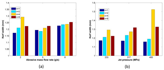
Figure 7.
Variation of the top kerf width for increasing number of passes in respect to (a) abrasive mass flow rate and (b) jet pressure.
Another important quantity indicating the deviation of the kerf geometry from the ideal one is the kerf taper angle. The measured values of the kerf taper angle are presented in Table 3 and depicted also in Figure 8a,b. From these figures, it can be seen at first that although a relatively large variation of the kerf taper angle value is obtained with an increasing number of passes at a low abrasive flow rate and jet pressure, as the abrasive flow rate increases, the effect of the number of passes is considerably lower and there is not a certain trend regarding the variation of kerf width angle. When the jet pressure values increase, the variation of kerf width angle values between cases with a different number of passes is also smaller than in the first four tests, but it can be seen that the kerf width angle increases gradually with the number of passes, and then, it is reduced for the cases with eight passes. This behavior exhibits similarities with the behavior observed regarding the kerf width in Figure 7b and can be probably attributed to the fact that the more rapid increase of kerf top width in comparison with the variation of the kerf width at lower heights leads to an increase of the taper angle, but as the kerf width is reduced for the cases with more than four passes, then the taper angle is also reduced. Moreover, a general observation is that the increase of abrasive mass flow rate led to a decrease of kerf taper angle values with a large decrease observed for ma over 2 g/s, whereas the different jet pressure values affected the kerf taper angle values to a lesser degree.
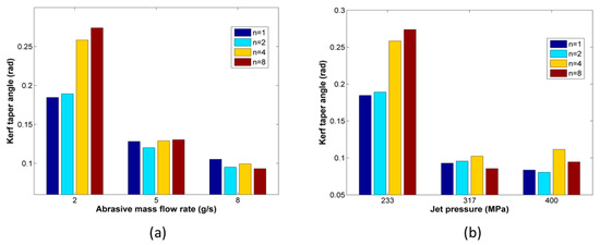
Figure 8.
Variation of the kerf taper angle for increasing number of passes in respect to (a) abrasive mass flow rate and (b) jet pressure.
3.4. Dependence of the MRR and Cutting Efficiency on the Number of Passes
After the dependence of kerf characteristics on the number of passes was determined, the correlation between the process efficiency, evaluated by means of the MRR, and the number of passes will be also investigated. The MRR was calculated from the obtained images from the microscope as follows: the area between the incision profile and the upper surface of each slot was determined at three characteristic cross-sections, as it was aforementioned in the Methodology section, and an average value for the cross-section area was obtained. Then, the MRR was determined as the product of the area and the slot length divided by the total machining time in every case. It is to be noted that the MRR value that is calculated corresponds to a mean value as in the cases with multiple passes, the total volume removed after all the passes is divided by the total machining time for this material removal, and consequently, it does not correspond to the MRR of an individual pass. This procedure was adopted in order to compare a single value between tests with a single and multiple passes and avoid reporting all the MRR values obtained at the end of every single pass in the multi-pass cases. The value of the MRR in every case is depicted in Figure 9. It is to be noted that the MRR deviations are related to both the variation of depth of penetration and kerf width as in each case, these two parameters define the general shape of the cross-section of the slot to a great extend.
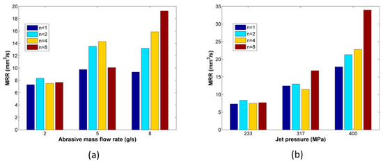
Figure 9.
Variation of the mean Material Removal Rate (MRR) for increasing number of passes in respect to the (a) abrasive mass flow rate and (b) jet pressure.
As can be seen from Figure 9a, the value of MRR is varying only slightly in the case with the lower abrasive mass flow rate and waterjet pressure values. However, at higher abrasive mass flow rate values, an increase of the number of passes leads to an increase of the MRR up to a point, which is mainly due to the fact that the depth of penetration also increases in this case as the waterjet energy becomes sufficient to overcome the resistance of the workpiece material. Similarly, at increased values of waterjet pressure, there is a clear increase of the MRR at higher numbers of passes, meaning that the material removal process becomes more efficient when multiple passes at higher traverse speed are preferred than single machining passes at lower traverse speeds.
Finally, from the calculated values regarding the volume of removed material, the cutting efficiency can be calculated for each experimental case. The procedure that was adopted for the calculation of the cutting efficiency was also adopted in previous works in the relevant literature [28] and defines the efficiency as the amount of material removed per unit mass of abrasive consumed. Thus, in order to calculate this quantity, the mass of workpiece material corresponding to the total removed volume from each slot will be divided by the total mass of abrasives consumed during this process, which will be calculated as the product of the abrasive mass flow rate and the total machining time in each case. It is to be noted that the cutting efficiency is a dimensionless quantity. The results regarding the cutting efficiency are displayed in Figure 10a,b.
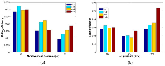
Figure 10.
Variation of the cutting efficiency for increasing number of passes in respect to (a) abrasive mass flow rate and (b) jet pressure.
From the results depicted in Figure 10a,b, it can be seen that the cutting efficiency values vary in the range of 0.02–0.05, which is in the same order of magnitude as the range calculated in the relevant literature [28]. By comparing the results depicted in Figure 9 and Figure 10, it can be seen that the variation of cutting efficiency values for different number of passes exhibits the same trends as the material removal rate values. Thus, for different abrasive mass flow rate values, the increase of machining passes leads usually to higher cutting efficiency in comparison to the efficiency of the single pass machining case, and the same is observed for increasing jet pressure, especially for the highest value of jet pressure where the efficiency for the case with eight passes is almost 1.5 times higher than that of the single pass case. Moreover, the increase of abrasive mass flow rate led to a clear decrease of cutting efficiency as the higher quantity of abrasive used did not lead to a proportional increase of removed volume. However, the increase of jet pressure did not lead to a definite trend of the variation of the cutting efficiency as the cutting efficiency values firstly decreased for jet pressure of 317 MPa and then increased for the highest value of jet pressure. Finally, from the obtained results, it can be deduced that a correct combination of process parameters and number of passes can lead to an increase of cutting efficiency, and it was shown that the use of multiple passes is more effective at higher abrasive mass flow rate and jet pressure values.
4. Conclusions
In the present work, AWJ milling experiments were conducted in order to determine the effect of performing multiple machining passes on kerf characteristics, material removal rate, and cutting efficiency during the AWJ milling of steel workpieces. The experiments were also conducted under various process conditions in order to observe whether a consistent trend exists regarding the effect of multi-pass AWJ or different behaviors are present. From the experimental results several useful conclusions were drawn.
Regarding the depth of penetration, different trends regarding the effect of the number of passes were observed depending on the process conditions. Thus, at lower abrasive mass flow rate and abrasive waterjet pressure values, the increase of the number of passes leads to a lower total depth of penetration, which is probably due to the insufficient energy of the waterjet to overcome easily the residual compressive stresses in the workpiece after each subsequent pass. However, at higher values of these two parameters, the depth of penetration increases with the number of passes up to a point, and finally, it can reach even twice the value obtained by a single pass for the same total machining time. Thus, the use of multiple passes is recommended to be chosen along with a relatively high abrasive mass flow rate and jet pressure values when larger depths are required.
Concerning the top kerf width, it was shown that the number of passes affects it to a lesser extent than that of the depth of penetration. The general trend that was observed was that the top kerf width increases slightly with an increase of the number of passes for the same total processing time. Similarly, the kerf taper angle was shown not to vary considerably with the number of passes in most cases. As with the top kerf width, in some cases, it was shown to exhibit a slight increase with the number of passes, but the effect of process parameters such as the abrasive mass flow rate was considerably more important on the kerf taper angle.
Finally, regarding the MRR and the cutting efficiency, it was shown that under appropriate process conditions, they can increase considerably with an increase of the number of passes, leading to an increase of the efficiency of the AWJ process. Specifically, in order to utilize the multi-pass technique effectively, it is recommended that it should be applied in conjunction with higher abrasive mass flow rate and jet pressure values. Thus, under certain process conditions, it is shown that the use of multiple passes can be preferable in comparison to single pass machining.
Author Contributions
Conceptualization, P.K.-O. and N.E.K.; Data curation P.K.-O., N.E.K., and R.K.; Investigation P.K.-O., E.L.P. and N.E.K.; Methodology, N.E.K. and P.K.-O.; Software, P.K.-O. and N.E.K.; Supervision, A.P.M., and R.K.; Validation, N.E.K. and P.K.-O.; Writing—original draft, P.K.-O. and N.E.K.; Writing—review and editing, P.K.-O., N.E.K., A.P.M. and E.L.P.; funding acquisition, R.K. and A.P.M.; All authors have read and agreed to the published version of the manuscript.
Funding
This research received no external funding.
Conflicts of Interest
The authors declare no conflict of interest.
References
- Yuvaraj, N.; Murugesan, P.K.; Mohan, M.; Khan, S.A.L.A. Abrasive Water Jet Machining process: A state of art of review. J. Manuf. Process. 2020, 49, 271–322. [Google Scholar] [CrossRef]
- Saravanan, S.; Vijayan, V.; Suthahar, S.J.; Balan, A.; Sankar, S.; Ravichandran, M. A review on recent progresses in machining methods based on abrasive water jet machining. Mater. Today Proc. 2020, 21, 116–122. [Google Scholar] [CrossRef]
- Liu, X.; Liang, Z.; Wen, G.; Yuan, X. Waterjet machining and research developments: A review. Int. J. Adv. Manuf. Technol. 2019, 102, 1257–1335. [Google Scholar] [CrossRef]
- Kale, A.; Singh, S.K.; Sateesh, N.; Subbiah, R. A review on abrasive water jet machining process and its process parameters. Mater. Today Proc. 2020, 26, 1032–1036. [Google Scholar] [CrossRef]
- Goutham, U.; Kanthababu, M.; Gowri, S.; Sunilkumar, K.R.; Mathanraj, M.; Jegaraj, J.J.R.; Balasubramanian, R. Condition Monitoring of Abrasive Waterjet Milling Using Acoustic Emission and Cutting Force. In Advances in Forming, Machining and Automation, Lecture Notes on Multidisciplinary Industrial Engineering; Shunmugam, M.S., Kanthababu, M., Eds.; Springer: Singapore, 2019; pp. 153–164. [Google Scholar]
- Husin, H.; Nawi, M.N.M.; Gebremariam, M.A.; Azhari, A. Investigation on the Effect of Abrasive Water Jet Parameter on Machining Stainless Steel. In Proceedings of the International Manufacturing Engineering Conference & The Asia Pacific Conference on Manufacturing Systems iMEC-APCOMS 2019, Putrajaya, Malaysia, 21–22 August 2019; Zahid, M.N.O., Aziz, R.A., Yusoff, A.R., Yahya, N.M., Aziz, F.A., Abu, M.Y., Eds.; Springer: Singapore, 2019; pp. 544–549. [Google Scholar]
- Yuvaraj, N.; Pradeep Kumar, M. Investigation of Process Parameters influence in AWJ Cutting of D2 steel. Mater. Manuf. Process. 2017, 32, 151–161. [Google Scholar] [CrossRef]
- Yuvaraj, N.; Pradeep Kumar, M. Surface integrity studies on abrasive water jet cutting of AISI D2 steel. Mater. Manuf. Process. 2017, 32, 162–170. [Google Scholar] [CrossRef]
- Kulisz, M.; Zagórski, I.; Korpysa, J. The Effect of Abrasive Water jet Machining Parameters on the Condition of Al-Si Alloy. Materials 2020, 13, 3122. [Google Scholar] [CrossRef]
- Hlaváčová, I.M.; Sadílek, M.; Váňová, P.; Szumilo, Š.; Tyč, M. Influence of steel structure on machinability by abrasive water jet. Materials 2020, 13, 4424. [Google Scholar] [CrossRef]
- Kong, M.; Axinte, D.; Voice, W. Aspects of material removal mechanism in plain waterjet milling on gamma titanium aluminide. J. Mater. Process. Technol. 2010, 210, 573–584. [Google Scholar] [CrossRef]
- Alberdi, A.; Rivero, A.; De Lacalle, L.N.L.; De Lacalle, L.N.L. Experimental Study of the Slot Overlapping and Tool Path Variation Effect in Abrasive Waterjet Milling. J. Manuf. Sci. Eng. 2011, 133, 034502. [Google Scholar] [CrossRef]
- Hashish, M. Controlled-Depth Milling of Isogrid Structures With AWJs. J. Manuf. Sci. Eng. 1998, 120, 21–27. [Google Scholar] [CrossRef]
- Fowler, G.; Shipway, P.H.; Pashby, I. Abrasive water-jet controlled depth milling of Ti6Al4V alloy—An investigation of the role of jet–workpiece traverse speed and abrasive grit size on the characteristics of the milled material. J. Mater. Process. Technol. 2005, 161, 407–414. [Google Scholar] [CrossRef]
- Wang, J.; Kuriyagawa, T.; Huang, C.Z. An Experimental Study to Enhance the Cutting Performance in Abrasive Water jet Machining. Mach. Sci. Technol. 2003, 7, 191–207. [Google Scholar] [CrossRef]
- Wang, J.; Guo, D. The cutting performance in multipass abrasive waterjet machining of industrial ceramics. J. Mater. Process. Technol. 2003, 133, 371–377. [Google Scholar] [CrossRef]
- Shanmugam, D.; Wang, J.; Liu, H. Minimisation of kerf tapers in abrasive water jet machining of alumina ceramics using a compensation technique. Int. J. Mach. Tools Manuf. 2008, 48, 1527–1534. [Google Scholar] [CrossRef]
- Wang, J.; Zhong, Y. Enhancing the depth of cut in abrasive water jet cutting of alumina ceramics by using multipass cutting with nozzle oscillation. Mach. Sci. Technol. 2009, 13, 76–91. [Google Scholar] [CrossRef]
- Wang, J. Depth of cut models for multipass abrasive water jet cutting of alumina ceramics with nozzle oscillation. Front. Mech. Eng. China 2009, 5, 19–32. [Google Scholar] [CrossRef]
- Boud, F.; Loo, L.; Kinnell, P. The Impact of Plain Water jet Machining on the Surface Integrity of Aluminium 7475. Procedia CIRP 2014, 13, 382–386. [Google Scholar] [CrossRef]
- Doreswamy, D.; Valavala, A.; Winitthumkul, N.; Devineni, A. Machining of D2 heat treated steel using abrasive water jet: The effect of standoff distance and feed rate on kerf width and surface roughness. Int. J. Res. Eng. Technol. 2014, 3, 417–421. [Google Scholar]
- Srinivasu, D.; Axinte, D.; Shipway, P.; Folkes, J. Influence of kinematic operating parameters on kerf geometry in abrasive water jet machining of silicon carbide ceramics. Int. J. Mach. Tools Manuf. 2009, 49, 1077–1088. [Google Scholar] [CrossRef]
- Miao, X.; Qiang, Z.; Wu, M.; Song, L.; Ye, F. The optimal cutting times of multipass abrasive water jet cutting. Int. J. Adv. Manuf. Technol. 2018, 97, 1779–1786. [Google Scholar] [CrossRef]
- Xiao, S.; Wang, P.; Gao, H.; Soulat, D. A study of abrasive water jet multi-pass cutting on kerf quality of carbon fiber-reinforced plastics. Int. J. Adv. Manuf. Technol. 2019, 105, 4527–4537. [Google Scholar] [CrossRef]
- Uhlmann, E.; Männel, C.; Braun, T. Efficient abrasive water jet milling for near-net-shape fabrication of difficult-to-cut materials. Int. J. Adv. Manuf. Technol. 2020, 111, 1–9. [Google Scholar] [CrossRef]
- Wang, J.; Xu, S. Enhancing the AWJ Cutting Performance by Multipass Machining with Controlled Nozzle Oscillation. Key Eng. Mater. 2005, 291-292, 453–458. [Google Scholar] [CrossRef]
- Wang, J. Techniques for Enhancing the Cutting Performance of Abrasive Water jets. Key Eng. Mater. 2004, 521–526. [Google Scholar] [CrossRef]
- Jegaraj, J.J.R.; Babu, N.R. A strategy for efficient and quality cutting of materials with abrasive waterjets considering the variation in orifice and focusing nozzle diameter. Int. J. Mach. Tools Manuf. 2005, 45, 1443–1450. [Google Scholar] [CrossRef]


Publisher’s Note: MDPI stays neutral with regard to jurisdictional claims in published maps and institutional affiliations. |
© 2021 by the authors. Licensee MDPI, Basel, Switzerland. This article is an open access article distributed under the terms and conditions of the Creative Commons Attribution (CC BY) license (http://creativecommons.org/licenses/by/4.0/).