Article

Microstructural and Mechanical Assessment of Camshafts Produced by Ductile Cast Iron Low Alloyed with Vanadium

by
Eduardo Colin García
1,
Alejandro Cruz Ramírez
1,*,
Guillermo Reyes Castellanos
1,
Jaime Téllez Ramírez
2 and
Antonio Magaña Hernández
2
1
Instituto Politécnico Nacional—ESIQIE, UPALM, México City 07738, Mexico
2
ARBOMEX S.A de C.V., Calle Norte 7 No. 102, Cd. Industrial, Celaya, Guanajuato 38010, Mexico
*
Author to whom correspondence should be addressed.
Metals 2021, 11(1), 146; https://doi.org/10.3390/met11010146
Submission received: 11 December 2020 / Revised: 3 January 2021 / Accepted: 6 January 2021 / Published: 13 January 2021

Abstract

:
In the present study, ductile iron camshafts low alloyed with 0.2 and 0.3 wt % vanadium were produced to study the microstructural and mechanical evaluation of lobes and camshaft. For this purpose, camshafts were produced in one of the largest manufacturers of the ductile iron camshaft in México by the phenolic urethane no-bake sand mold casting method. The microstructure of the lobes was studied in three zones located at the top, middle, and bottom of the lobes by optical microscopy, and mechanical tests were performed on lobes and camshafts. A homogeneous distribution of spheroidal graphite with high nodularity for both castings was obtained from the regions of the lobes analyzed. The high cooling rate on the lobe surfaces enabled us to obtain a high nodule count of a smaller size instead of the middle region where big nodules with a low nodule count are presented. An inverse chill behavior was found in the middle region of the lobes where there is an increase in the concentration of carbide-forming elements, leading to the highest micro-hardness values in this region. The tensile properties were increased when the vanadium contents were increased; however, the toughness and ductility of the as-cast alloys were decreased as a result of the increase of the volume fraction of carbide particles.

1. Introduction

The automotive sector has reached a very high production capacity in recent decades. Cast iron and aluminum alloys are the most commonly cast metal parts used in the automotive due to their low cost, ease of machining, ease of casting into complex shapes and desired physical properties. The camshaft, crankshaft, gearbox, engine block, automobile suspension, cylinder head, and steering systems are some of the casting products from foundries used in automotive industries [1]. Among these, the camshaft is a rotating shaft used to push open valves at the proper time in the engine cycle, either directly or through mechanical or hydraulic linkage (push rods, rocker arms, tappets). The most modern automobile engines have one or more camshafts mounted in the engine head (overhead cam). Camshafts are generally made of forged steel or cast iron and are driven off the crankshaft through a belt or chain (timing chain) [2]. The radial lobes consist of a circular disc with a semi-oval triangular protrusion. The lobes are designed to control the open and close intervals of the inlet and exhaust poppet valves. During functioning, camshafts are subject to bending and torsional stresses, and lobes surfaces are highly loaded, and the high toughness and wear resistance are essential for this component [3,4]. The adequate combination of strength, toughness, and wear resistance of the component can be achieved by controlling the microstructure through careful selection of chemical composition (alloying elements) as well as appropriate heat treatment parameters [5]. Today, due to many advantages, camshafts are produced from gray, ductile cast iron and also by machining of steel. However, some forged steel components have been replaced by austempered ductile iron (ADI) mainly in automotive applications. These include crankshafts, camshafts, differential gears, chain links, spiral, ring, and pinion gears and universal joins [6,7]. Gray cast iron is used for the manufacturing of camshafts and to obtain a wear-resistant lobe surface of cast camshafts; chills are used to increase the cooling rate, promote directional solidification, and obtain a hard ledeburitic structure [8,9]. Nevertheless, a layer or black line [10] is formed during heat transfer from the solidifying casting to chills due to a difference of the thermal conductivities decreasing the wear resistance of the camshafts. Y. Yang et al. [10] studied the mechanism of black line defect formation in a chilled cast iron camshaft by computer simulation and the manufacturing operation results. The black line composed of pearlite and graphite was formed inside the chilled area of the lobe and showed lower hardness results than those obtained for the chilled zone. L. Cenk [11] studied the mechanical and microstructure properties of chilled cast iron camshaft. Because of the strong cooling effect of chill, top lobes are rapidly solidified with a deeper chilled zone and the lowest dendrite arm spacing than the central zone of the lobe where a slower solidification is carried out. The high cooling rate refines both the hard ledeburitic phase and fine pearlite, increasing the hardness. Laser surface hardening is an effective process used to increase working characteristics of product surfaces of high load components like camshafts lobes, crankshafts necks, gears, among others. Hard facings introduced by melting and alloying via high energy are new trends in the surface strengthening of ductile iron [12,13]. Ductile iron is more convenient in terms of production costs and lighter compared to machining production methods of steel. ADI, when compared with steel, has low material and production costs, low density, a good processing ability, and a high vibration damping ability. These advantages make ADI attractive for industrial applications. For the automotive industry, ADI has an important task as a structural material that should have a good wear resistance and tensile strength in applications such as camshafts [14,15]. The successful production of ADI requires close control between the foundry and heat treatment processes. The minimum characteristics in ductile iron needed to obtain ADIs are [16]: (a) Uniform distribution of nodule count of 100 nodule mm−2; (b) Nodularity of 85%; (c) 0.5% maximum of carbides and non-metallic inclusions; (d) 1% maximum of porosity and micro-shrinkage, and (e) Homogeneous chemical composition. In addition to the proper chemical compositions, suitable heat treatment parameters are also required to produce high-performance ADI. The number and shape of the graphite nodules are important when producing ductile iron. These characteristics are described as the nodule count and nodularity, respectively [16]. It is difficult to have good control in the graphite features (nodule count, nodule size, nodularity) during the manufacturing of casting with different thicknesses. It has been reported [17] that when the thickness of the casting is increasing, the cooling rate decreases, the nodule count decreases, and consequently, the nodule size is increased. To decrease and avoid the imperfections like micro-shrinkage, graphite deterioration, carbide formation, and alloying elements segregation during ductile iron manufacturing, it is necessary to monitor the casting variables such as treatment of hot metal, inoculation, tapping and pouring temperature, gating and feeding system [18]. It is shown that particle hardening belongs to the most effective strengthening mechanism in metals. Given the attractive effects of vanadium on the transformation of steels, it was expected that the beneficial effects of microalloying elements may be exploited on ductile iron and ADI production [19]. Vanadium is a strong carbide forming element, especially at more than 0.15 wt %. The addition of vanadium to the ductile cast iron increases the strength and hardness by an increase of the pearlite amount but elongation is decreased, besides, the nodule count and nodularity of graphite are decreased [20]. This work aims to evaluate the microstructural and mechanical properties of camshafts and lobes of ductile iron low alloyed with 0.2 and 0.3 wt % of vanadium under the operational parameters of one of the largest manufacturers of the ductile iron camshaft. The changes in nodule count, nodularity, nodule size, porosity, and the micro-constituents formed for the lobes concerning the vanadium content are presented. The as-cast ductile iron low alloyed with vanadium were considered as raw material for the heat treatment of ADI camshaft production.

2. Materials and Methods

Two casting alloys identified as C-0.2V and C-0.3V for camshaft alloyed with 0.2 wt %V and 0.3 wt %V respectively were produced in ARBOMEX S.A de C.V., a Mexican company located at Celaya and Apaseo Guanajuato, México; specialized in camshafts manufacturing. The results of the camshafts low alloyed with vanadium were compared with the standard camshaft iron properties to be considered as a raw material for further ADI camshaft production.

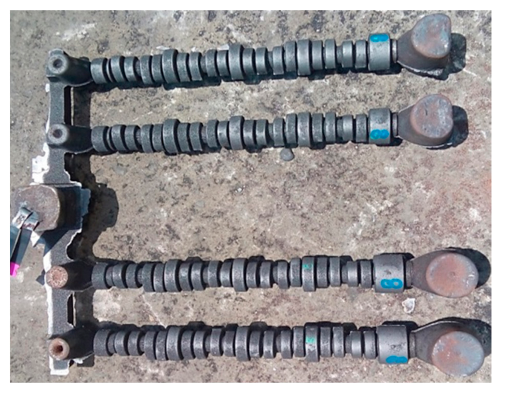
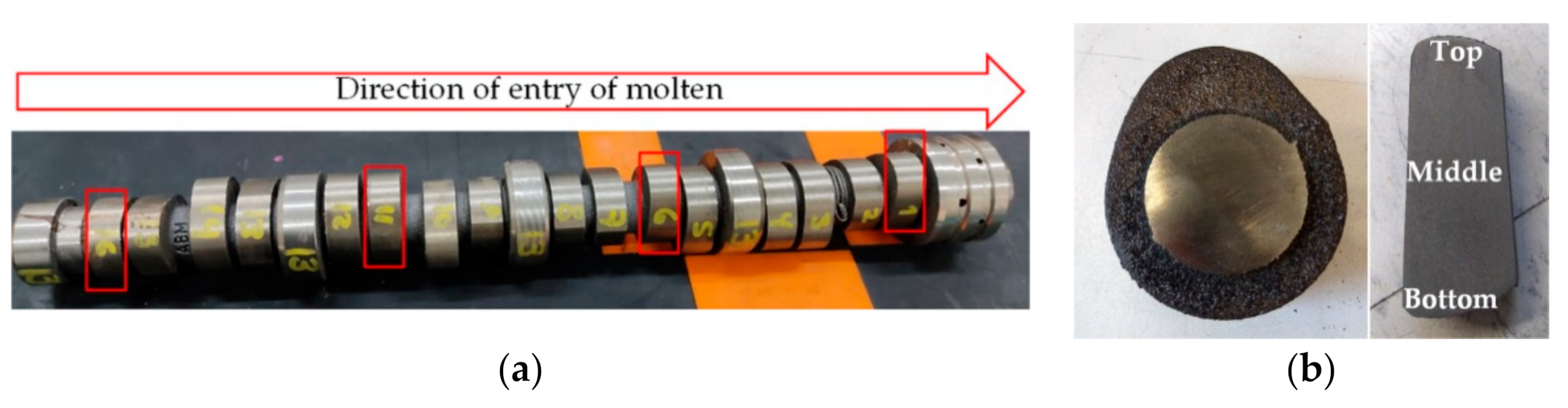
2.1. Casting of Camshafts

A Dual Track Coreless Induction Furnace (Inductotherm Corp., Rancocas, NJ, USA) of medium frequency (300 Hz) Inductotherm of 3500 kW potency capacity and 6 Ton per hour of furnace capacity was used to melt the alloys. The base iron was produced by using 30 wt % low carbon steel, 30 wt % iron burrs from the machining area, and cast-iron scrap as balance. All the materials were melted and homogenized at 1400–1440 °C. The base iron was poured at 1470–1520 °C into a preheated ladle where the chemical composition was adjusted by adding the ferroalloys: FeSi (70%), high purity carbon, and FeV (61.5%). The ductile iron alloyed was poured into a tundish ladle where 1.05 wt % of MgFeSi (45% Si, 7.5% Mg, 0.8% Al, 2.6% Ca, 2.48% rare earths) was added as a nodulizing agent. Later, the melt was poured into a ladle and inoculated with the inoculant FeSi (70% Si+ 0.8% Ca, 3.9% Al) by the ladle inoculation method, where the inoculant was added to the metal stream as it flowed from the nodulized ladle into a preheated pouring type shank ladle. Each of the two cast alloys was then poured at 1385–1420 °C into phenolic urethane no-bake sand molds casting method which was previously obtained by tooling with four cavities of camshafts (intake and exhaust lobes) for HEMI V8 engine to obtain about 100 camshafts for each alloy. Figure 1 shows the camshafts produced containing 16 lobes. The nominal chemical composition in the camshafts was analyzed by an OBLF GS 1000 II emission optic spectrograph (OBLF Gesellschaft für Elektronik und Feinwerktechnik mbH, Witten, Germany) and the reported values in Table 1 are the average of three measurements on each cast alloy. Carbon and sulfur content was determined by combustion analysis using a Leco C/S 744 analyzer (LECO Corporation, St. Joseph, MI, USA).

2.2. Microstructural Characterization

Four camshafts were randomly selected from each alloy and the lobes were sectioned on the cross-section with a metallographic fine cutter disc and liquid cooling. The lobes 1, 6, 11, and 16 were selected because they are located at the beginning, middle and the end of the camshaft which presents different solidification behavior. Figure 2 shows the camshaft with the selected lobes and three regions analyzed from the top area (nose of the lobe), middle, and the bottom area on the lobes for microstructural evaluation. Standard metallography techniques (mechanical grinding and polishing followed by etching with 2% nital) were employed to reveal the different micro-constituents of the cast alloys. Optical microscopy was performed on polished and etched specimens by using an optical microscope Olympus PMG-3 model (Olympus Corporation, Center Valley, PA, USA), the ASTM A 247 standard, and the image-analyzer (Olympus Corporation, Center Valley, PA, USA). With the software Image J 4.1 version (NIH, Bethesda, MD, USA). The graphite morphology was rated for the nodule count, nodularity, and average nodule size by ASTM standard A 247 on the unetched samples. The nodularity by using object area is defined in ASTM A247 as: % Nodularity = [Areaacceptable particles/(Areaacceptable + unacceptable particles)]×100 [21]. Phase volume fraction measurements including nodule graphite, pearlite, ferrite, and carbides were carried out using the image-analyzer with the software Image J 4.1. Carbides were revealed by etching for 3 min with a water solution of ammonium persulfate (10% vol) [22]. Particles with a diameter smaller than 10 μm were neglected in the nodule count and were considered as defects (porosity, inclusions, and micro-shrinkages) that do not influence the solidification morphology [21]. The optical microscopy measurements represent the average of three different zones closer to the selected regions on each lobe (Figure 2b) and the deviation standard values are reported.

2.3. Mechanical Properties
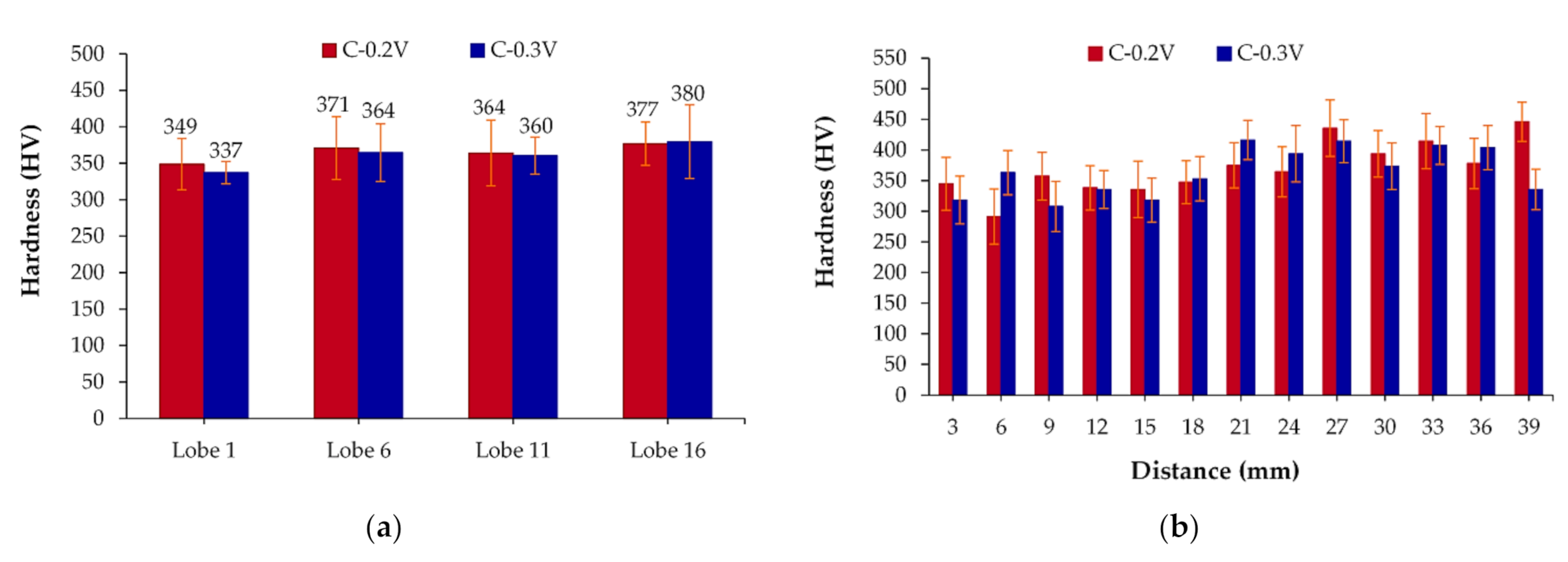
Four camshafts were randomly selected from each alloy for the camshafts produced to obtain samples for the tensile strength and impact properties by the Charpy test. The average and deviation standard values are reported

2.3.1. Hardness

Vickers hardness measurements were made on the polished surfaces of the as-cast cross-section of the lobes by using a Mitutoyo hardness tester HM200 (Mitutoyo Corporation, Kanagawa, Japan), software AVPACK20 (Mitutoyo Corporation, Kanagawa, Japan), and an applied load of 0.05 N under the standard specification of ASTM E92. At least between 7 and 13 measurements were taken every 0.3 mm of each lobe from the top (nose) area to the bottom area and the average of the measurements is reported for each lobe and cast alloy.

2.3.2. Tensile Test

Tensile testing was carried out at room temperature using a universal testing machine (Shimadzu Corporation, Nakagyo-ku, Kyoto, Japan) Shimadzu of 100 kN with 10 mm/min cross-head speed. The size and geometry of the specimens followed the specifications of ASTM E 8. Four specimens from each cast alloy were taken from the camshaft and were tested for tensile test, and the average of the measurements are reported.

2.3.3. Charpy Impact Test

Charpy unnotched bars impact tests were machined based on the specifications of ASTM A 327. The maximum energy of the machine was 220 J, and impact velocity of 4.5 m/s. Four specimens from each cast alloy were taken from the camshaft and were tested for impact test in a Tinius Olsen Charpy impact testing machine (Tinius Olsen TMC, Hursham, PA, USA) tensile test, and the average of the measurements is reported.

3. Results and Discussions

Table 1 and Table 2 show the chemical composition and the microstructural and mechanical properties of the standard camshaft iron, respectively.

3.1. Chemical Composition

The chemical composition analyzed in the as-cast alloys low alloyed with vanadium is shown in Table 3. The chemical composition of the cast alloys produced was similar and the only difference was the amount of vanadium added to the castings. In both cases the equivalent carbon was hyper-eutectic. High manganese and copper amounts are used to obtain a high amount of pearlite in the camshafts produced. Manganese is a carbide forming element which segregates in eutectic cell boundaries during solidification [23] while vanadium is a strong carbide forming element that was added to increase the strength and hardness of ductile irons [24]. The residual magnesium content of 0.04% was obtained for an adequate nodule formation, as well as the typical residual sulfur after treatment is recommended [25].

3.2. Microstructural Characterization

The microstructural characterization was carried out on the two ductile irons alloyed with 0.2 and 0.3 wt % V, a similar behavior was observed for the two alloys. The microstructural results for the four lobes and three regions analyzed of ductile iron alloyed with 0.2 and 0.3 wt % V are reported in Appendix A. Figure A1 and Figure A2 show the unetched microstructure of both ductile irons alloyed with vanadium. It is observed a homogeneous distribution of spheroidal graphite with high nodularity for the casting. The middle zone of the lobe shows big nodules with low nodule count instead of the zones of the top and bottom of the lobes where the nodule count is increased but the nodule size is smaller than in the middle region. Figure A3 and Figure A4 show the etched microstructure of both ductile irons alloyed with vanadium. The microstructure is constituted by graphite nodules in a fully pearlitic matrix with small amounts of white zones attributed mainly to ferrite and carbides. Figure A5 shows the etched microstructures of the ductile iron unalloyed and alloyed with 0.2 and 0.3 wt %V at higher magnifications for the middle zone of the lobes. It is observed more clearly the pearlite lamellae presented as the main microconstituent for the three alloys. Small amounts of ferrite surround the nodules mainly for the unalloyed ductile iron. A small number of carbides with elongated shapes are observed for the ductile iron alloyed with 0.3 wt %V. To exclude the ferrite phase and identify only the carbides, an etching with ammonium persulfate was carried out, and Figure A6 and Figure A7 show clearly the formation of the carbides identified as white regions.
The quantification of the graphite features and microconstituents for the regions analyzed in the lobes for camshaft alloyed with 0.2 and 0.3 wt % V are shown in Figure 3 and Figure 4, respectively. It is observed from Figure 3a and Figure 4a that the nodule count has increased for the top and bottom zones of the lobes while the nodule count decrease for the middle region of the lobes. The nodule size shows an opposite behavior than the nodule count, when the nodule count increases, the nodule size decrease. From Figure 3a and Figure 4a, it is observed that the middle region of the lobes shows a bigger nodule size. The middle region of the lobes slows down the cooling rate than the external regions (top and bottom) which results in a low nodule count of a bigger size. Nodule count is especially important when alloy additions are made to the casting. Low nodule counts lead to the larger spacing between the graphite nodules and larger regions of segregation are expected while higher nodule counts will break up the segregated regions. It has been reported for conventional ductile iron and austempered ductile iron [26,27] that the nodule size is inversely proportional to the nodule count for both sand and metal mold ingots. The nodularity is kept almost constant for the regions and lobes analyzed, reaching values higher than 80%. Particles lower than 10 μm were considered as inclusions, porosities, and micro-shrinkage which were lower than 1% on average for the lobes analyzed. From Figure 3b and Figure 4b, it is observed that the graphite amount is kept almost constant for the lobes and regions evaluated. The major constituent in the camshaft is the pearlite reaching higher values than 80% on average for the lobes reported. Lobe 16 shows the lower amount of pearlite and the higher amount of ferrite, this behavior is due to the closed position of this lobe with the runner and a feeder as can be observed in Figure 1. The slow solidification in this zone allows forming a higher amount of ferrite and graphite phases. Therefore, the gating and feeding systems used for camshafts manufacturing are one of the most important parameters that will influence the solidification pattern. As can be observed from Figure 1, lobe 1 is located closer to a feeder while lobe 16 is closer to the runner and a feeder which supply a slow cooling rate in the region closer to lobe 16. Despite vanadium and manganese are strong carbide formers, the level of carbides determined for both camshafts alloyed with vanadium showed an amount lower than 1% on average. It is worth to mention that the highest carbide formation is located in the middle of the lobes instead of the external parts of the lobes. This behavior is related to the inverse chill, where there is a segregation of carbide-forming elements to the middle zone of the camshaft increasing the concentration of these elements in the last liquid to solidify promoting eutectic iron carbide formation [28]. M. Rezvani et al. [24] reported that fine particles of V4C3 are formed when vanadium is added to ductile iron and these particles are uniformly distributed in the ferrite zone and as can be observed in Figure 3b and Figure 4b where lobes 11 and 16 contain the higher amount of ferrite.
The graphite features and the volume fraction of phases formed in both cast alloys are shown in Table 4. These results represent the average of four lobes and three regions analyzed for two camshafts for each alloy.
The results in Table 4 show that when the vanadium content is increased from 0.2 to 0.3 wt%, the nodule count decrease, and the nodule size and volume fraction of graphite increase, these behavior match with the results reported by the M. Rezvani et al. [24]. The low addition of vanadium to the ductile iron shows a similar shape of the nodule distribution as can be observed in the nodularity results. As expected, when the vanadium content is increased, the volume fraction of carbide is increased. The ferrite content decrease when the vanadium content is increased; however, when the pearlite content decrease, these results are directly related to the gating and feeding system used for the camshaft manufacturing, where the lobes closer to the running and feeder of the camshaft are cooled slowly due to a hotter zone. The porosity, inclusions, and micro-shrinkages are lower than 1% for both alloys. The results in Table 4 show a slight variation between the properties evaluated for both alloys. Therefore, the low content of vanadium added for the ductile cast iron has a negligible effect on the solidification pattern.
Comparing the results obtained from Table 2 and Table 4, it is observed that the addition of vanadium to the standard camshaft iron slightly decrease the nodularity, the nodule count is increased with a decrease in the nodule size. The amount of ferrite is decreased while the pearlite is increased. It is notorious that the increase in the carbide formation when the vanadium is added to the standard camshaft iron. The graphite amount is decreased to the 0.2 wt % V addition and then increased for the alloy containing 0.3 wt% V. In general the graphite features and phases formed behavior is expected for the low vanadium addition to the standard camshaft iron.

3.3. Mechanical Properties

The Vickers hardness test was conducted on the cross-section of the camshaft lobes surfaces from the top area to the bottom. Figure 5a shows the micro-hardness average results of the lobes for the camshafts alloyed with 0.2 and 0.3 wt % V. Lobe 16 shows the higher hardness values for both cast alloys while lobe 1 showed the lowest hardness results. This behavior is directly related to the carbide amount where lobe 16 presents a higher carbide amount that lobe 1. As can be observed from Figure 3b and Figure 4b, the highest carbide formation is located at the middle of the lobes instead of its external parts, thus high hardness values are expected in the middle region of the lobes. Figure 5b shows the micro-hardness results from the top to the bottom part of lobe 6 for both casting alloys. It is observed that the higher micro-hardness values are located in the middle region of the lobe where a high carbide amount is located due to the inverse chill phenomena. A similar trend was observed for the lobes analyzed. The average hardness obtained was 365 HV and 360 HV for the camshaft produced with 0.2 wt % V and 0.3 wt % V, respectively.
Tensile tests were carried out for three specimens obtained from camshaft for the two ductile casts alloyed with vanadium. Typical strain-stress curves were obtained and the variation of yield strength and tensile strength with the vanadium content is shown in Figure 6. The yield strength shows a slight increase from 559 MPa to 588 MPa when the vanadium content is increased from 0.2 to 0.3 wt % in the ductile iron. The highest ultimate tensile strength value (782 MPa) was obtained for ductile iron alloyed with 0.3 wt % V. It is widely known that particle hardening belongs to the most effective strengthening in metals. The additions of vanadium to ductile iron resulted in an increase of the strength of ductile iron as a result of the volume fraction of particles containing vanadium, considered in this work as the carbide particles. The vanadium content can reduce the diffusion rate of carbon in austenite in ductile iron and strongly promote the formation of carbide, these particles during the solidification can block the grown of grains [29]. In addition, the increasing of the volume fraction of pearlite and decreasing the pearlite interlamellar spacing also contributes to improving the strengthening of ductile iron [24]. However, in this work, the volume fraction of pearlite in both camshafts alloys are similar, therefore the main difference is the volume fraction of carbides. D. Padan et al. [19] reported a yield and tensile strength values of 494 and 675 MPa, respectively for a ductile cast iron alloyed with 0.1 wt % V in the as-cast condition, while M. Rezvani et al. [24] reported a yield and tensile strength values of 457 and 670 MPa, respectively for a ductile cast iron alloyed with 0.27 wt % V. The tensile results obtained in this work are higher than the results reported in the literature [19,24].
The influence of vanadium content on the impact toughness and elongation is shown in Figure 7. The highest values of elongation and energy absorbed were obtained for the camshaft alloyed with 0.2 wt % V. In general, the impact strength increases with increasing ductility (% elongation) [29]. The impact energy values and elongation are in the range reported by M. Idham et al. [30] and are higher than those reported by H. Bakhshinezhad et al. [31] where the vanadium amount was increased to 0.87 and 1.45 wt %. The impact toughness and ductility are improved to low vanadium contents but reduce when the vanadium content is increased. The reduction in total elongation and toughness is attributed to the increase of volume fraction of carbides which affect the continuity of the matrix acting as crack initiation sites for the fracture.
The mechanical results for the standard camshaft iron reported in Table 2 compared with the results in Figure 5, Figure 6 and Figure 7 show that the vanadium addition increases the hardness and strength of the ductile iron. The hardness was increased from 287 HV for the unalloyed ductile iron to 365 HV on average for the ductile iron alloyed with 0.2 wt % V while the ductile iron alloyed with 0.3 wt % V showed a hardness of 360 HV on average. The yield and tensile strength are increased from 528 and 735 MPa to 588 and 782 MPa for the unalloyed ductile iron and the ductile iron alloyed with 0.3 wt % V, respectively. The elongation is slightly decreased when the vanadium content was increased, however, the impact energy was improved from 9.3 to 14.8 J for the ductile iron alloyed with 0.2wt % V.
The results of the microstructural and mechanical properties of the camshafts low alloyed with vanadium are remarkable to be considered as a raw material for the austempering heat treatment for camshafts production.

4. Conclusions

In this work, ductile iron camshafts low alloyed with 0.2 and 0.3 wt % vanadium were produced and a microstructural and mechanical evaluation of lobes and camshaft were carried out. The results obtained can be summarized as follows:
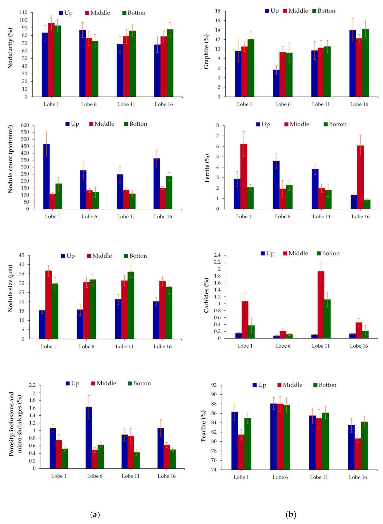
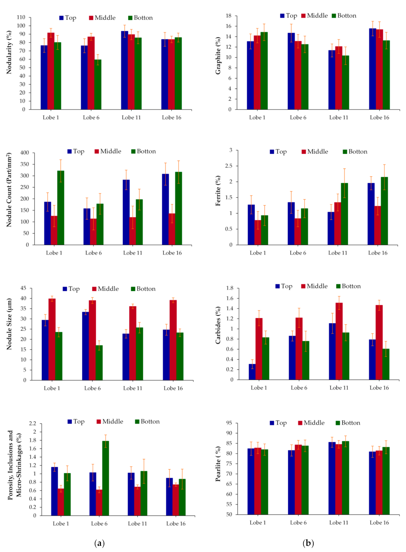
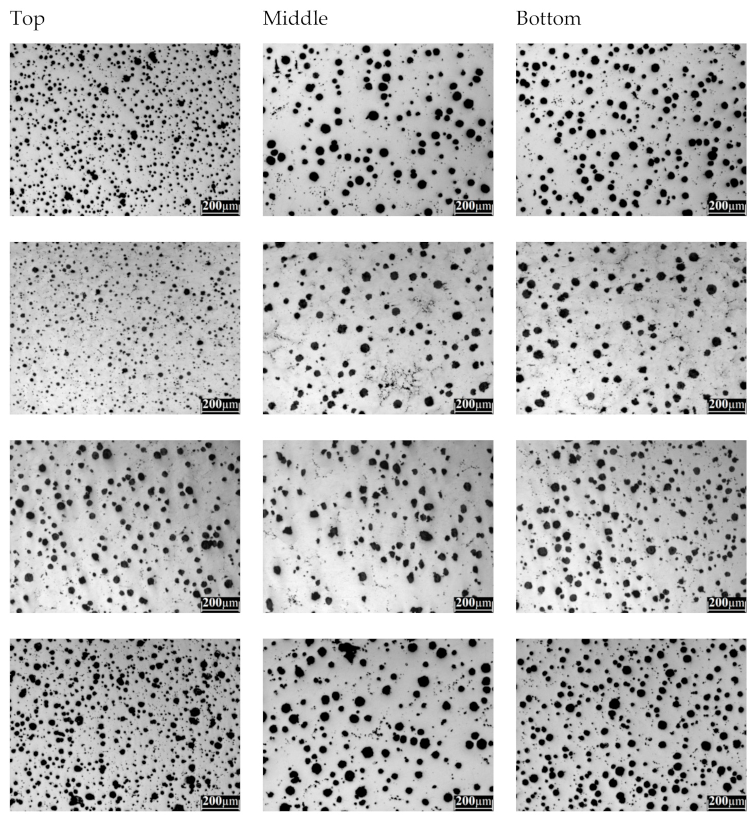
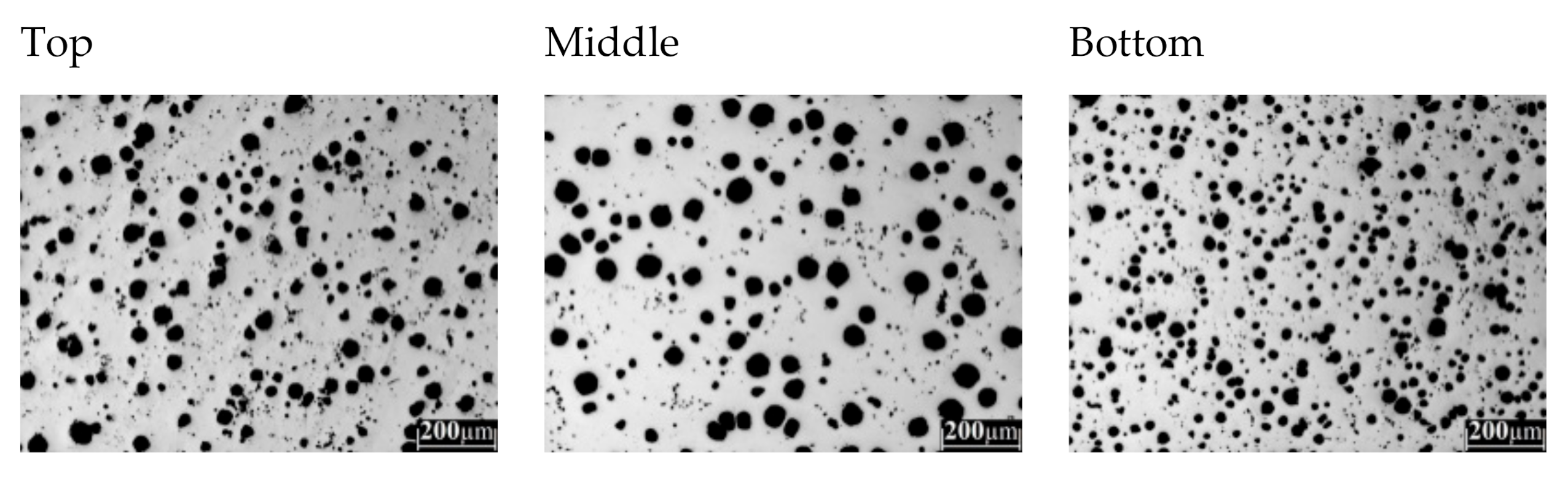
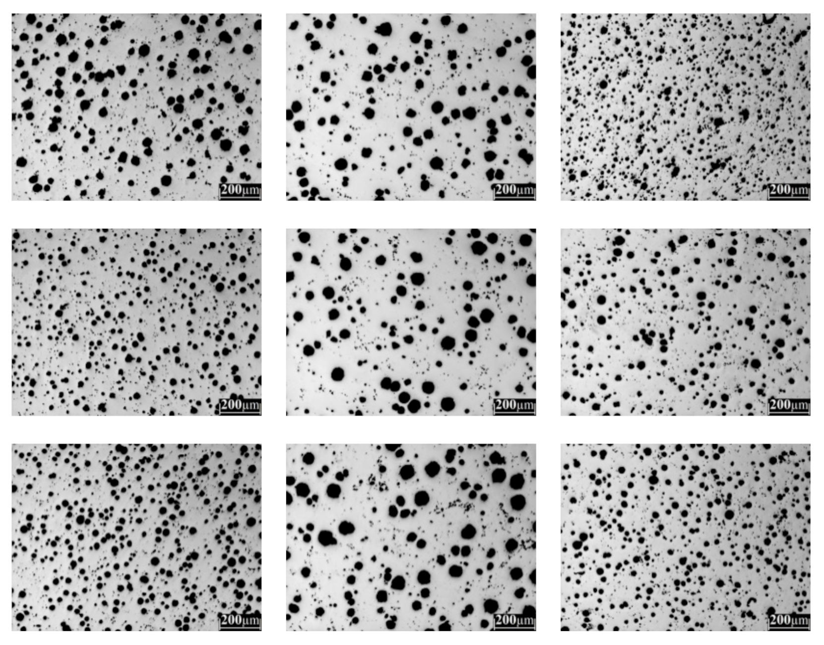
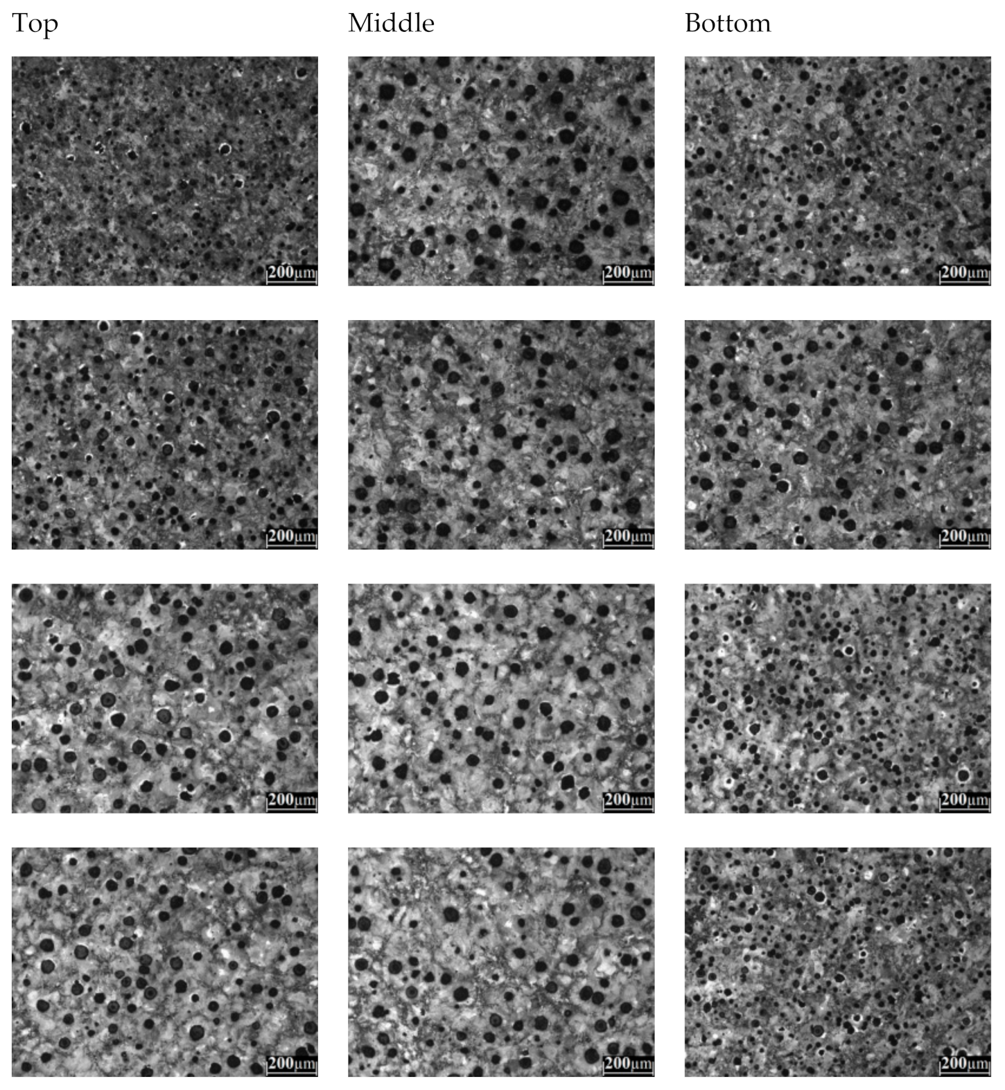
  • The cooling rate of the camshafts and lobes depends on their section size and the position of the feeding and gating systems. The middle zone of the lobe shows big nodules with low nodule count instead of the zones of the top and bottom of the lobes where the nodule count is increased but with a smaller nodule size.
  • A high nodularity upper than 80% was obtained for the lobes analyzed and the porosities, non-metallic inclusions, and micro-shrinkages were kept lower than 1% in both as-cast alloys.
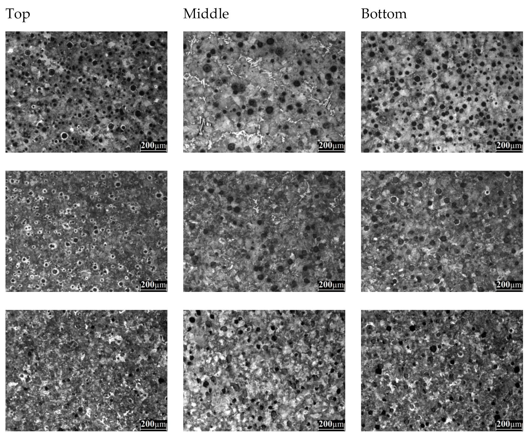
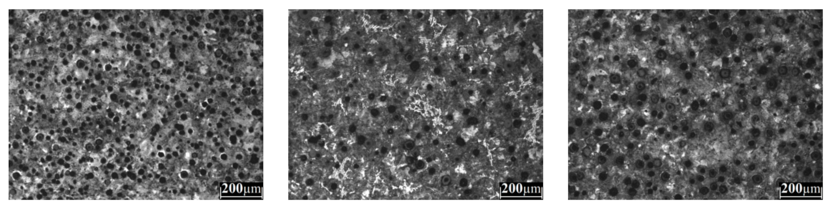
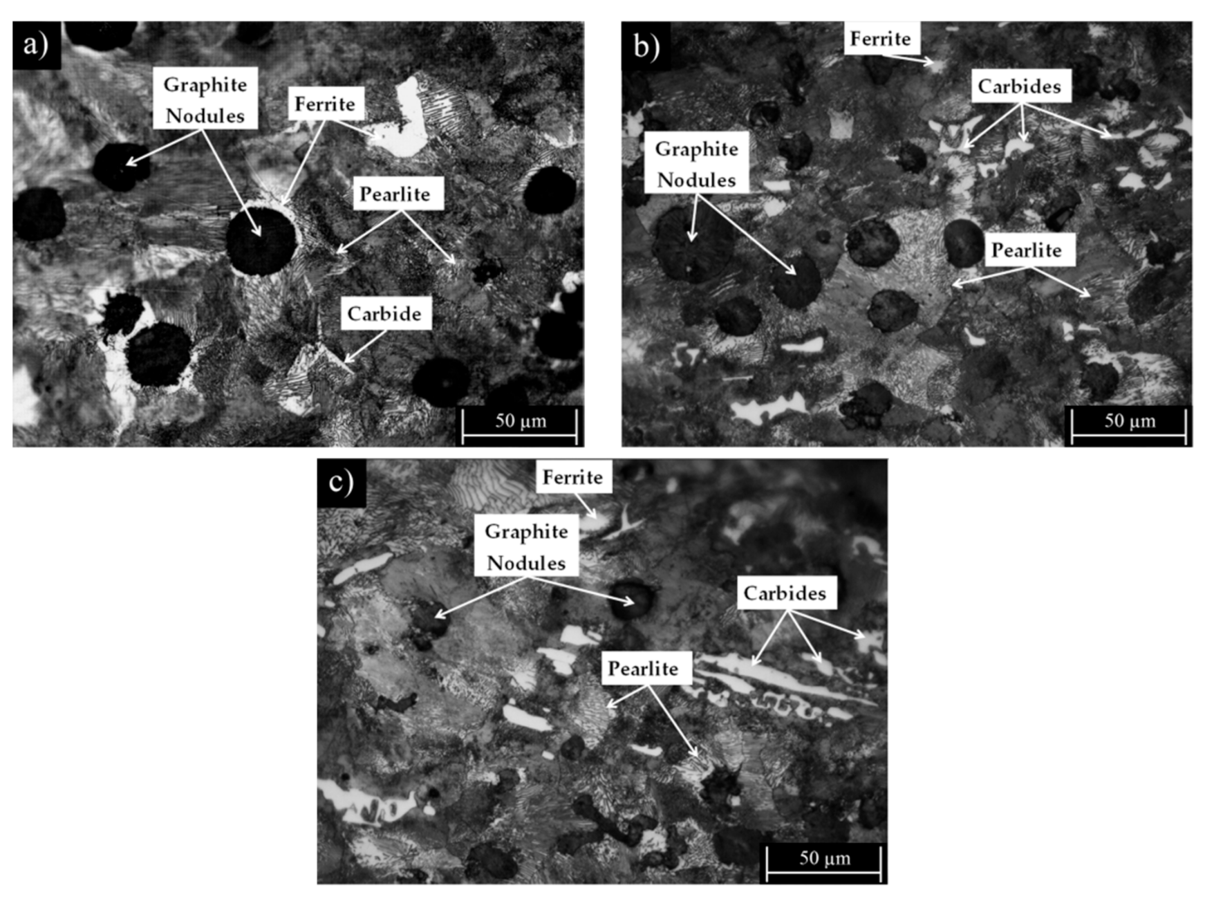
  • The amounts of copper, manganese, and vanadium added to the cast alloys allow obtaining graphite nodules in a matrix constituted mainly by pearlite, and lower amounts of ferrite and carbides were obtained.
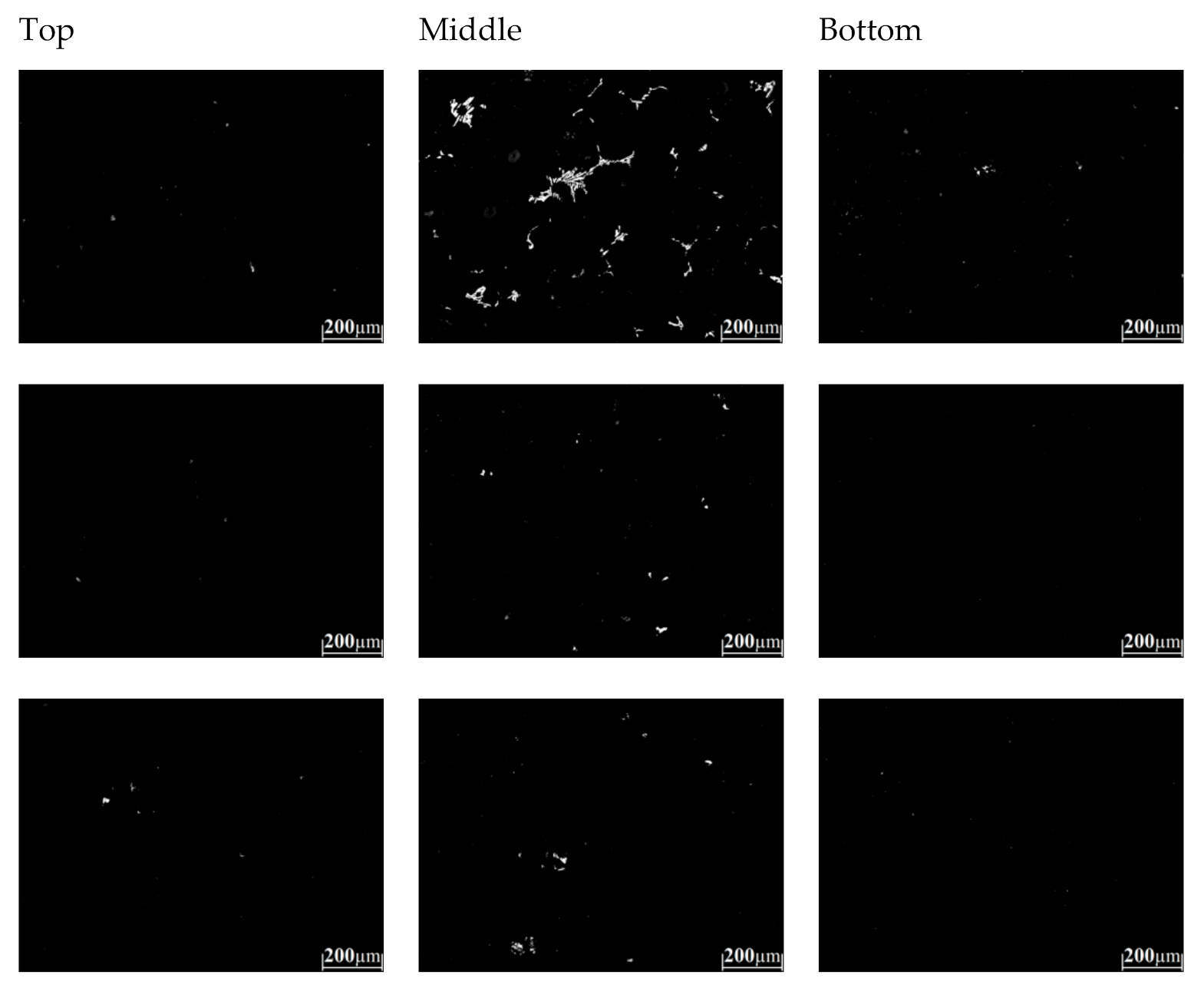
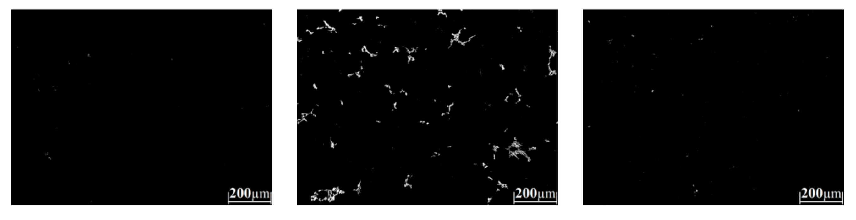
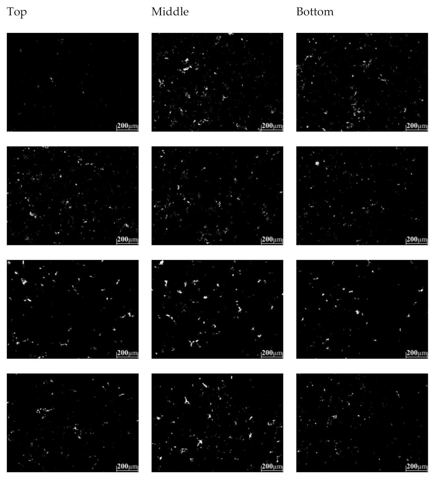
  • The highest carbide formation is located at the middle of the lobes due to the inverse chill, where there is a segregation of carbide-forming elements to the middle zone of the camshaft increasing the concentration of these elements in the last liquid to solidify.
  • The highest micro-hardness results were obtained for the middle region of the lobes where the high amount of carbides are located.
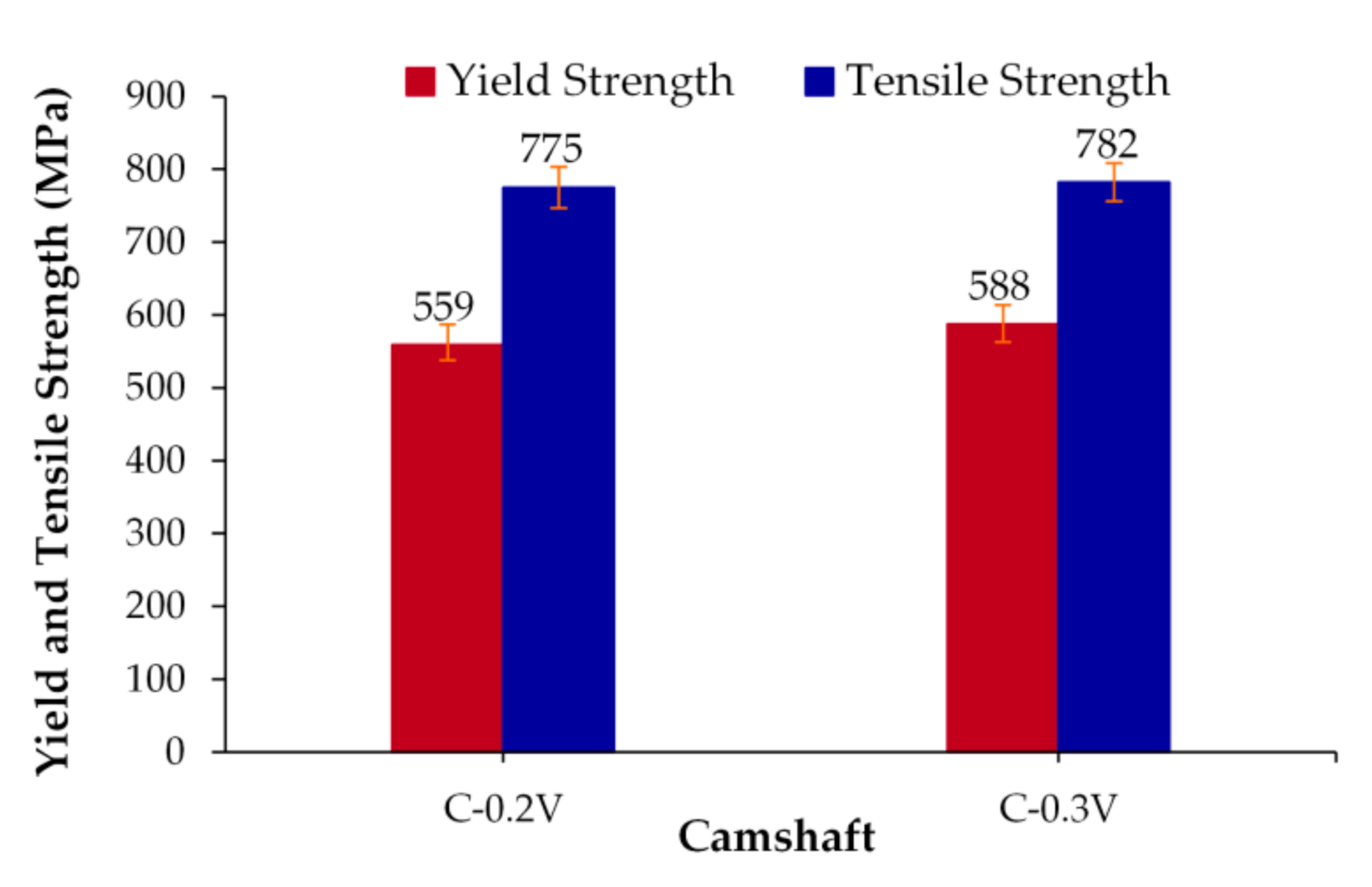
  • The essential mechanical properties of hardness and strength desired in camshafts were increased by adding low amounts of vanadium to standard ductile iron.
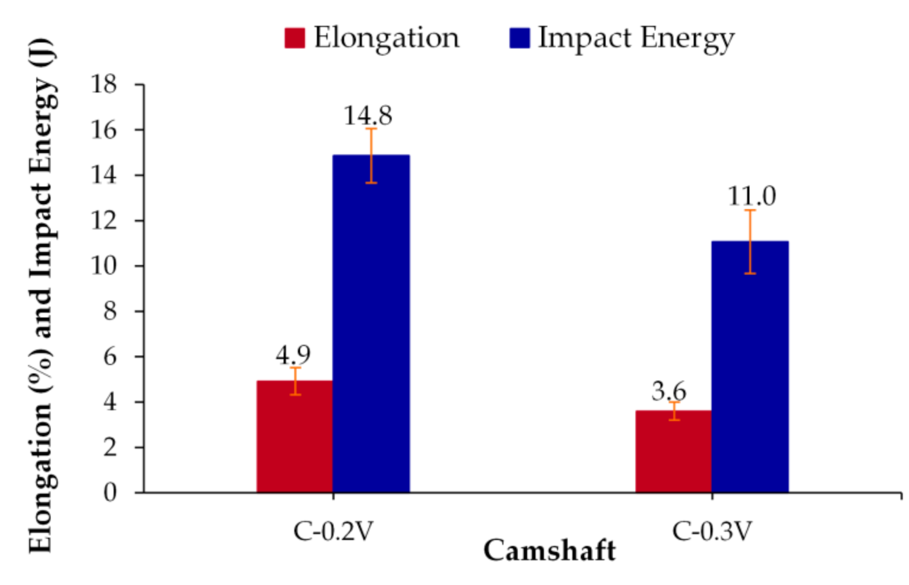
  • The yield and ultimate tensile strengths show an increase when the vanadium contents are increased; however, there is a slight reduction in the toughness and ductility of the as-cast alloys as a result of the increase of volume fraction of carbide particles that increase strength but act as crack initiation sites for the fracture.

Author Contributions

Conceptualization, A.C.R. and J.T.R.; Data curation, G.R.C.; Formal analysis, E.C.G. and A.C.R.; Investigation, E.C.G. and A.M.H.; Methodology, A.C.R., E.C.G., G.R.C., J.T.R. and A.M.H.; Project administration, J.T.R.; Writing—original draft, E.C.G.; Writing—review and editing, A.C.R. All authors have read and agreed to the published version of the manuscript.

Funding

This research received no external funding.

Institutional Review Board Statement

Not applicable.

Informed Consent Statement

Informed consent was obtained from all subjects involved in the study.

Data Availability Statement

No additional data.

Acknowledgments

The authors wish to thank the enterprise ARBOMEX S.A. de C.V. for the facilities given for the trial’s development. A.C.R., G.R.C., and E.C.G. wish to thank Institutions CONACyT, SNI, COFAA, and SIP-Instituto Politécnico Nacional for their permanent assistance to the Process Metallurgy Group at ESIQIE-Metallurgy and Materials Department.

Conflicts of Interest

The authors declare no conflict of interest.

Appendix A

Figure A1. Unetched microstructure of the ductile iron alloyed with 0.2 wt % V for different lobes and regions.
Metals 11 00146 g0a1
Figure A2. Unetched microstructure of the ductile iron alloyed with 0.3 wt % V for different lobes and regions.
Metals 11 00146 g0a2aMetals 11 00146 g0a2b
Figure A3. Etched microstructure of the ductile iron alloyed with 0.2 wt % V for different lobes and regions.
Metals 11 00146 g0a3aMetals 11 00146 g0a3b
Figure A4. Etched microstructure of the ductile iron alloyed with 0.3 wt % V for different lobes and regions.
Metals 11 00146 g0a4
Figure A5. Etched microstructure at high magnifications for the (a) unalloyed ductile iron, (b) ductile iron alloyed with 0.2 wt % V, and (c) ductile iron alloyed with 0.3 wt % V for different the middle zone of the lobes.
Metals 11 00146 g0a5
Figure A6. Etched microstructure with ammonium persulfate reveals the carbides phase (white regions) of the ductile iron alloyed with 0.2 wt % V for different lobes and regions.
Metals 11 00146 g0a6aMetals 11 00146 g0a6b
Figure A7. Etched microstructure with ammonium persulfate reveals the carbides phase (white regions) of the ductile iron alloyed with 0.3 wt % V for different lobes and regions.
Metals 11 00146 g0a7

References

  1. Foundry Products: Competitive Conditions in the U.S. Market. Available online: https://www.usitc.gov/publications/332/pub3771.pdf (accessed on 12 November 2020).
  2. Pulkrabeth, W.W. Engineering Fundamentals of the Internal Combustion Engine; Prentice-Hall: Upper Saddle River, NJ, USA, 2004; pp. 18–19. [Google Scholar]
  3. Bayrakceken, H.; Ucun, I.; Tasgetiren, S. Fracture analysis of a camshaft made from nodular cast iron. Eng. Fail. Anal. 2006, 13, 1240–1245. [Google Scholar] [CrossRef]
  4. Wang, G.; Taylor, D.; Bouquin, B.; Devlukia, J.; Ciepalowicz, A. Prediction of fatigue failure in a camshaft using the crack modelling method. Eng. Fail. Anal. 2000, 7, 189–197. [Google Scholar] [CrossRef]
  5. Dymek, S.; Blicharski, M.; Morgiel, J.; Fras, E. TEM investigation of ductile iron alloyed with vanadium. J. Microsc. 2010, 237, 461–464. [Google Scholar] [CrossRef] [PubMed]
  6. Karaca, B.; Simsir, M. The effects of austempering and induction hardening on the wear properties of camshaft made of ductile cast iron. Acta Phys. Pol. 2017, 131, 448–452. [Google Scholar] [CrossRef]
  7. Ping, L.; Bahadur, S.; Verhoeven, J.D. Friction and wear behavior of high silicon bainitic structures in austempered cast iron and steel. Wear 1990, 138, 269–284. [Google Scholar] [CrossRef]
  8. Chernyshev, A.N.; Kaplina, I.N.; Serapin, M.I. Surface hardening with remelting of functional surfaces of cast iron camshafts. Met. Sci. Heat Treat. 1996, 38, 440–442. [Google Scholar] [CrossRef]
  9. Gafur, M.A.; Haque, M.N.; Prabhu, K.N. Effect of chill thickness and superheat on casting/chill interfacial heat transfer during solidification of commercially pure aluminum. J. Mater. Process. Tech. 2003, 133, 257–265. [Google Scholar] [CrossRef]
  10. Yang, Y.; Rosochowski, A.; Wang, X.; Jiang, Y. Mechanism of “black line” formation in chilled cast iron camshafts. J. Mater. Process. Tech. 2004, 145, 264–267. [Google Scholar] [CrossRef]
  11. Kumruoǧlu, L.C. Mechanical and microstructure properties of chilled cast iron camshaft: Experimental and computer aided evaluation. Mater. Design 2009, 30, 927–938. [Google Scholar] [CrossRef]
  12. Fernández-Vicente, A.; Pellizzari, M.; Arias, J.L. Feasibility of laser surface treatment of pearlitic and bainitic ductile irons for hot rolls. J. Mater. Process. Technol. 2012, 212, 989–1002. [Google Scholar] [CrossRef]
  13. Benyounis, K.Y.; Fakron, O.M.A.; Abboud, J.H.; Olabi, A.G.; Hashmi, M.J.S. Surface melting of nodular cast iron by Nd-YAG laser and TIG. J. Mater. Process. Technol. 2005, 170, 127–132. [Google Scholar] [CrossRef]
  14. Meena, A.; El Mansori, M. Study of dry and minimum quantity lubrication drilling of novel austempered ductile iron (ADI) for automotive applications. Wear 2011, 9–10, 2412–2416. [Google Scholar] [CrossRef]
  15. Cetin, B.; Meco, H.; Davut, K.; Arslan, E.; Can, M. Microstructural analysis of austempered ductile iron castings. Hitt. J. Sci. Eng. 2016, 3, 29–34. [Google Scholar] [CrossRef] [Green Version]
  16. Keough, J.R.; Hayrynen, K.L. Design with austempered ductile iron (ADI). AFS Proc. 2010, 10–129, 1–15. [Google Scholar]
  17. Hemanth, J. Effect of cooling rate on dendrite arm spacing (DAS), eutectic cell count (ECC) and ultimate tensile strength (UTS) of austempered chilled ductile iron. Mater. Design 2000, 21, 1–8. [Google Scholar] [CrossRef]
  18. Austempered ductile-iron castings—Advantages, production, properties and specifications. Mater. Design 1992, 13, 295–297.
  19. Padan, D.S. Microalloying in Austempered Ductile Iron (ADI). AFS 2012, 12–19, 1–12. [Google Scholar]
  20. Sadighzadeh, B.A. Effect of alloying elements on austempered ductile iron (ADI) properties and its process: Review. China Foundry 2015, 12, 54–70. [Google Scholar]
  21. Ruxanda, R.; Stefanescu, D.M.; Piwonka, T.S. Microstructure characterization of ductile thin wall iron castings. Trans. Am. Foundry Soc. 2002, 110, 1131–1147. [Google Scholar]
  22. Pedro, D.I.; Dommarco, R.C. Rolling contact fatigue resistance of Carbidic Austempered Ductile Iron (CADI). Wear 2019, 418–419, 94–101. [Google Scholar] [CrossRef]
  23. Hamid, A.A.S.; Elliot, R. Influence of austenitising temperature on austempering of an Mn-Mo-Cu alloyed ductile iron Part 1—Austempering kinetics and the processing window. Mater. Sci. Tech. 1996, 12, 1021–1031. [Google Scholar] [CrossRef]
  24. Rezvani, M.; Harding, R.A.; Campbell, J. The effect of vanadium in as-cast ductile iron. Int. J. Cast Metal. Res. 1997, 10, 1–15. [Google Scholar] [CrossRef]
  25. Cueva, G.; Sinatora, A.; Guesser, W.L.; Tschiptschin, A.P. Wear resistance of cast irons used in brake disc rotors. Wear 2003, 255, 1256–1260. [Google Scholar] [CrossRef] [Green Version]
  26. Colin-García, E.; Cruz-Ramírez, A.; Reyes-Castellanos, G.; Romero-Serrano, J.A.; Sánchez-Alvarado, R.; Hernández-Chávez, M. Influence of nickel addition and casting modulus on the properties of hypo-eutectic ductile cast iron. J. Min. Metall. Sect. Metall. 2019, 55, 283–293. [Google Scholar] [CrossRef]
  27. Mohammed, K.J. Investigation of some alloyed (SG) ductile irons. Unified J. Eng. Manuf. Technol. 2016, 1, 005–010. [Google Scholar]
  28. Han, C.F.; Sun, Y.F.; Wu, Y.; Ma, Y.H. Effects of vanadium and austempering temperature on microstructure and properties of CADI. Metallogr. Microstruct. Anal. 2015, 4, 135–145. [Google Scholar] [CrossRef]
  29. Refaey, A.; Fatahalla, N. Effect of microstructure on properties of ADI and low alloyed ductile iron. J. Mater. Sci. 2003, 38, 351–362. [Google Scholar] [CrossRef]
  30. Idham, M.F.; Abdullah, B.; Jaffar, A.; Ibrahim, M.H.; Ramli, A. The effect of mechanical properties of 2.0% vanadium ductile iron after double quenching method. Adv. Mat. Res. 2012, 399–401, 172–175. [Google Scholar] [CrossRef]
  31. Bakhshinezhada, H.; Honarbakhshraoufa, A.; Abdollah-Pour, H. A study of effect of vanadium on microstructure and mechanical properties of as-cast and austempered ductile iron. Phys. Met. Metallogr. 2019, 120, 447–483. [Google Scholar] [CrossRef]
Figure 1. Type of camshaft with 16 lobes.
Metals 11 00146 g001
Figure 2. (a) Camshaft with 16 lobes and (b) regions analyzed from the top to the bottom of the lobes.
Metals 11 00146 g002
Figure 3. Microstructural characterization of the ductile iron alloyed with 0.2 wt % V for different lobes and regions analyzed to (a) graphite features (b) microconstituents.
Metals 11 00146 g003
Figure 4. Microstructural characterization of the ductile iron alloyed with 0.3 wt % V for different lobes and regions analyzed to (a) graphite features (b) microconstituents.
Metals 11 00146 g004
Figure 5. Vickers hardness measurements for the ductile iron alloyed with 0.2 and 0.3 wt % V to (a) different lobes and, (b) from top to bottom of lobe 6.
Metals 11 00146 g005
Figure 6. Influence of vanadium content on yield and tensile strength.
Metals 11 00146 g006
Figure 7. Influence of vanadium content on impact toughness and elongation.
Metals 11 00146 g007
Table 1. Chemical composition of the standard camshaft (wt. %).
SampleCSiMnPSMgVNiAlCuCrMoTiSnPbCE
C-0V3.612.360.830.0150.0080.0460.0080.1030.0130.8790.0430.030.0040.0030.0014.40
Balance Fe. CE: Carbon Equivalent = %C + 1/3%Si + 1/3%P.
Table 2. Graphite features, the volume fraction of phases, and mechanical properties for the standard camshaft.
CharacteristicC-0V
Nodularity (%)85.17 ± 2.64
Nodule count (particles/mm2)155 ± 28.67
Nodule size (µm)32.49 ± 3.69
Porosity, inclusions and micro-shrinkages (%)0.27 ± 0.08
Graphite (%)12.84 ± 0.55
Ferrite (%)5.3 ± 0.20
Pearlite (%)81.43 ± 0.20
Carbides (%)0.156 ± 0.04
Hardness (HV)287 ± 15
Yield strength (MPa)528 ± 29
Tensile strength (MPa)735 ± 32
Elongation (%)5.42 ± 0.63
Impact energy (J)9.3 ± 1.4
Table 3. Chemical composition of camshafts alloyed with V (wt. %).
SampleCSiMnPSMgVNiAlCuCrMoTiSnPbCE
C-0.2V3.612.490.960.0160.0130.0450.20.1170.0160.9430.20.0980.0060.0030.0014.44
C-0.3V3.582.480.940.0160.0120.0410.30.1150.0160.9680.130.0920.0060.0040.0014.41
Balance Fe. CE: Carbon Equivalent = %C + 1/3%Si + 1/3%P.
Table 4. Graphite features and volume fraction of phases formed for the camshafts alloyed with V.
CharacteristicC-0.2VC-0.3V
Nodularity (%)81.33 ± 6.3382.85 ± 6.41
Nodule count (particles/mm2)210 ± 46.34203 ± 42.58
Nodule size (µm)27.32 ± 1.5729.46 ± 1.15
Porosity, inclusions and micro-shrinkages (%)0.78 ± 0.080.95 ± 0.12
Graphite (%)10.60 ± 2.2213.36 ± 1.49
Ferrite (%)2.99 ± 0.511.33 ± 0.35
Pearlite (%)85.14 ± 2.1983.39 ± 1.56
Carbides (%)0.49 ± 0.120.97 ± 0.16
Publisher’s Note: MDPI stays neutral with regard to jurisdictional claims in published maps and institutional affiliations.

