Article

Effect of Processing Parameters on Interphase Precipitation and Mechanical Properties in Novel CrVNb Microalloyed Steel

by
Andrii Kostryzhev
1,2,
Chris Killmore
1,3 and
Elena Pereloma
1,2,4,*
1
ARC Research Hub for Australian Steel Manufacturing, University of Wollongong, Wollongong, NSW 2500, Australia
2
School of Mechanical, Materials, Mechatronic and Biomedical Engineering, University of Wollongong, Wollongong, NSW 2522, Australia
3
BlueScope Steel Limited, Five Islands Rd., Port Kembla, NSW 2505, Australia
4
UOW Electron Microscopy Centre, University of Wollongong, Wollongong, NSW 2522, Australia
*
Author to whom correspondence should be addressed.
Metals 2021, 11(1), 107; https://doi.org/10.3390/met11010107
Submission received: 13 December 2020 / Revised: 3 January 2021 / Accepted: 4 January 2021 / Published: 7 January 2021
(This article belongs to the Special Issue Novel Steel Compositions and Processing Technologies)

Abstract

:
Novel steel microalloyed with 0.73 (Cr + V + Nb) has been subjected to thermomechanical processing (TMP) with varying parameters to simultaneously maximise the steel strength and ductility. Optical and electron microscopy studies coupled with uniaxial tensile testing were carried out to analyse the processing-microstructure-properties relationship. For the suggested steel composition, the simultaneously highest yield stress (960 MPa), ultimate tensile strength (1100 MPa), and elongation to failure (25%) were achieved following simulated coiling at 650 °C and holding for 30 min. The variation in the finish rolling temperature affects the ferrite grain size and the ratio of precipitates formed in austenite and ferrite. If a significant amount of solute is consumed for precipitation in austenite and during subsequent growth of strain-induced precipitates, then a lower fraction of interphase and random precipitates forms in ferrite resulting in a lower strength. Extended time at a simulated coiling temperature resulted in the growth of interphase precipitates and precipitation of random ones in ferrite. Fine tuning of TMP parameters is required to maximise the contribution to strength arising from different microstructural features.

1. Introduction

Growing competition in the steel market initiates further research into new steel compositions and processing technologies which would guarantee the highest properties at a lowest cost. One of the key directions to reduce the steel manufacturing cost is to simplify its chemical composition. However, reduced contents of microalloying elements may adversely affect mechanical properties, as a result of decreased strengthening contributions from solid solute atoms and precipitates. Therefore, lean steel compositions require sophisticated processing schedules to compensate for the strength loss.
Interphase precipitation of carbides/carbonitrides (when particles align in rows) was shown to be an effective way to utilise microalloying elements as precipitation strengthening agents [1,2,3,4,5,6,7]. This mode of precipitation occurs during austenite to ferrite transformation if the transformation start temperature is approximately equal to the precipitation temperature. During migration of the austenite–ferrite interface, the particles nucleate at the interface and continue growing in ferrite [8,9,10,11]. Interphase precipitation could contribute up to 400 MPa to the yield stress (Table 1). Such a high contribution originates from a combination of high particle number density and fine particle size of ~3–5 nm.
Since the 1960s, interphase precipitation has been observed in steels microalloyed with various carbonitride forming elements: Nb [12,13,14,15], Ti [2,16,17,18], and V [1,10,19,20,21,22,23]. A substantial body of research has been dedicated to investigate the effect of Mo on interphase precipitation, especially in Ti-microalloyed steels [2,6,24,25,26,27,28]. TiMoC particles were found to nucleate as Mo-rich clusters and then grow into particles via increasing the Ti concentration [28]. Mo reduces the lattice misfit between the carbide and ferrite, thus making the nucleation process easier [29]. The presence of Mo in TiC is thermodynamically unfavourable [30]. Thus, due to the slow rate of Mo diffusing out of the carbide, the coarsening process of particles is slowed down. It was also shown that Mo slows down the coarsening rate of TiC clusters [31]. Therefore, TiC particle sizes and intersheet spacing become smaller with Mo addition [32]. The overall steel strength was shown to depend on Ti/Mo ratio as it affects the absolute values of particle sizes and number densities [2].
The effects of various processing parameters on interphase precipitation has been recently summarised in review papers [33,34] showing that processing has a complex effect on the interphase particle characteristics and mechanical properties. For example, TiMoC clusters/precipitates became finer and their intersheet spacing decreased with hot deformation, compared to the non-deformed condition [27,35]. Similarly, ~50% reduction in intersheet spacing of VC was noted after deformation of austenite prior to phase transformation [36]. In 0.06C-0.1Ti-0.5Cr (wt.%; hereafter all compositions are given in wt.%) steel, a decrease in holding temperature from 720 to 640 °C resulted in more planar rows of TiC, their size and intersheet spacing decreased, number density increased, and the steel hardness increased [37]. In another Ti-microalloyed steel containing 0.06C-0.1Ti-0.2Mo, a decrease in temperature from 720 to 630 °C also resulted in the sheet spacing decreasing and strength increasing, although various morphologies (irregular and regular intersheet spacing, and curved or straight row lines) of interphase precipitates were observed in different grains [24]. Similarly to Ti-microalloyed steels, in a V steel containing 0.1C-0.2V-0.5Mo, a decrease in holding temperature from 650 to 630 °C coupled with Mo additions decreased the intersheet spacing and particle size, leading to a strength increase; however, this effect was more prominent in the V steel compared to the Ti steel [38]. Despite this noted increase in the precipitation strengthening contribution with a decrease in holding temperature, the strength dependence on temperature shows a peak. Thus, in 0.05C-0.05Nb steel, hardness increased with decreasing temperature from 750 to 650 °C, due to decreasing intersheet spacing; however at 600 °C the hardness decreased as no precipitation occurred [39]. In another 0.06C-0.056Nb steel, interphase NbC precipitated at 750 °C and did not precipitate at the lower temperature of 600 °C; however, the strength was higher after coiling at 600 °C due to finer ferrite grain size [40]. In 0.11C-0.11Ti-0.21Mo steel, the intersheet spacing decreased with decreasing temperature from 700 to 650 °C; however, hardness was maximised at 670 °C for undeformed and at 660 °C for deformed conditions, as below these temperatures, precipitation ceased [41]. The strength dependence on holding time also exhibits a maximum. For example, in 0.04C-0.05Ti-0.22Mo steel, the strength maximum was observed after 18 min holding time at 650 °C [42]; in 0.04C-0.1Ti-0.22Mo steel—at 40 min holding time at 650 °C [31]; and in 0.07C-0.086Nb-0.047Ti steel—at 60 min holding time at 650 °C [43].
In this work, we investigate a novel CrVNb-microalloyed steel processed to obtain interphase precipitation. Nb and V were expected to precipitate as NbVCN, and Cr was added to mainly increase solubility of other microalloying elements and reduce the precipitate sizes [44]. Effects of three processing parameters were considered and discussed: finish deformation temperature, simulated coiling (holding) temperature and time.
Table 1. Strengthening contribution from interphase precipitation (published data).
Steel Composition, wt.%Processingσppt, MPaMethod of CalculationReference
0.1C-0.1Ti-0.6CrReheat at 1050 °C, cooling at 20 °C/s, holding at 650 °C for 2 min160Based on the experiment compared to steel without Ti[17]
0.06C-0.1Ti-0.5Cr0.5 strain at 880 °C, cooling at 30 °C/s, holding at 760–640 °C for 5 min220–320Dislocation looping[37]
0.06C-0.1Ti-0.2MoHeating to 1200 °C, cooling at 15 °C/s, holding at 720–630 °C for 30 min230–400Dislocation looping[24]
0.04C-0.09Ti-0.2MoFinish rolling at 900 °C, cooling at 10 °C/s, holding at 620 for 60 min300Subtraction of other strengthening mechanisms from experimental yield strength value[2]
0.1C-0.2TiHeating to 1200 °C, cooling at 10 °C/s, holding at 630 °C for 90 min240Dislocation looping[38]
0.1C-0.2Ti-0.5Mo260
0.1C-0.2V130
0.1C-0.2V-0.5Mo240
0.1C-0.2Ti-0.6CrReheat at 1050 °C, cooling at 20° C/s, holding at 650 °C for 8 s326Dislocation looping[18]
0.1C-0.2Ti-0.1Al300
0.1C-0.04Nb-0.11TiFinish rolling at 900 °C, cooling at 10 °C/s, coiling at 650 °C112Dislocation looping[16]
0.44C-0.3VReheating at 1200 °C, holding at 650 °C for 2 min180Based on the experiment compared to steel without V[23]
0.44C-0.5V320
0.07C-0.086Nb-0.047TiFrom room temperature reheating to 650 °C, holding for 60 min234Subtraction of other strengthening mechanisms from experimental yield strength value[43]
0.023C-0.34NbFinish forged at 910 °C, cooled at 0.13 °C/s to room temperature210Dislocation looping[13]
0.08C-0.035Nb-0.085Ti-0.11MoFinish rolling at 835 °C, cooling at 2 °C/s to 600 °C, no holding320Dislocation looping[32]
0.08C-0.047Nb-0.079Ti170
~(0.08 ± 0.003)C-1.5Mn-0.3Si-0.2Ni-(0.0131 ± 0.0002)N-0.68 (Cr + Mo + V + Nb)Total strain 1.35, coiling at 600 °C, 15 min holding401Dislocation cutting[7]

2. Materials and Methods

The steel containing ~(0.08 ± 0.003)C, 1.5Mn, 0.3Si, 0.2Ni, 0.03Al, 0.003S, 0.015P, (0.0131 ± 0.0002)N, and 0.73 (Cr + V + Nb) (wt %) was melted by Hycast Metals Pty Ltd. (Smithfield, NSW, Australia) and cast as 75 × 100 × 150 mm3 blocks. The blocks were homogenised at 1250 °C for 30 h, to equalise chemical composition, then forged in the temperature range of 1250–900 °C along the 100 mm side to 28 mm plate thickness, to assure 3.5 times reduction of the as-cast microstructure. The forged plates were machined into standard 20 × 15 × 10 mm3 Gleeble samples. Thermomechanical processing (TMP) was carried out in a Gleeble 3500 simulator (Dynamic Systems Inc., Poestenkill, NY, USA) using the following schedules: austenitising at 1250 °C for 180 s, followed by a set of deformation in both recrystallised and non-recrystallised austenite regions to a total strain of 1.35. In two sets of samples, the finish rolling temperatures were 900 °C and 850 °C, designated as high finish temperature (HFT) and low finish temperature (LFT). The simulated coiling was carried out at 650 °C or 600 °C (CT) for either 15 or 30 min, followed by air cooling to room temperature. Here, we present data for six selected TMP conditions, which are subsequently referred to according to their TMP schedule as HFT/CT/time and LFT/CT/time.
Microstructure characterisation was carried out using optical, scanning (SEM) and transmission (TEM) electron microscopy. For optical and SEM microscopy the Gleeble samples were cut parallel to the ND-RD plane, where ND is the compression direction and RD represents the rolling direction in Gleeble simulation. For TEM and tensile properties testing the samples were cut parallel to the ND-TD plane, where TD represents the transverse direction in the simulation. Optical and SEM sample preparation included polishing with SiC papers and diamond suspensions followed by etching with 5% Nital. Foils for TEM were prepared by hand polishing with a number of SiC papers followed by electropolishing using a Tenupol machine. Optical microscopy was conducted on a Leica DM6000M microscope (Leica Mikrosysteme Vertrieb GmbH, Wetzlar, Germany) equipped with Leica Application Suite (LAS) 4.0.0 image processing software (Leica Mikrosysteme Vertrieb GmbH, Wetzlar, Germany). SEM was carried out using a JEOL 7001F FEG scanning electron microscope (JEOL, Tokyo, Japan) operating at 15 kV for imaging and 7 kV for energy dispersive X-ray spectroscopy (EDS) of precipitates. For the determination of ferrite grain sizes, more than 400 grain were manually measured for each of six studied conditions. In the SEM, visible size range precipitation was scarce. Thus, only a limited number of <100 particles was analysed for each processing condition with respect to precipitate sizes, number density and area fraction values. The EDS semi-quantitative point analysis was carried out for 20+ particles for each studied condition using an AZtec 2.0 Oxford SEM EDS system (Oxford Instruments, Abingdon, United Kingdom). Transmission electron microscopy was conducted on a JEOL JEM2010 TEM microscope (JEOL, Tokyo, Japan). For the analysis of interphase precipitation several grains were imaged for each processing condition. The precipitates type was analysed using selected area diffraction. The foil thickness was measured to be ~80 nm; a convergent beam diffraction technique was applied for this measurement. Imaging of dislocation structure was performed near the [011] ferrite grain zone axis. Tensile testing for the six studied conditions was carried out on a Kammrath and Weiss GmbH mini-tensile stage (Kammrath and Weiss GmbH, Dortmund, Germany). Testing was performed using 3 mm wide, 1 mm thick, and 7 mm gauge length flat specimens. The constant crosshead speed of 7 μm·s−1 was applied and resulted in 1 × 10⁻³ s−1 strain rate. Two specimens were tested per condition.

3. Results

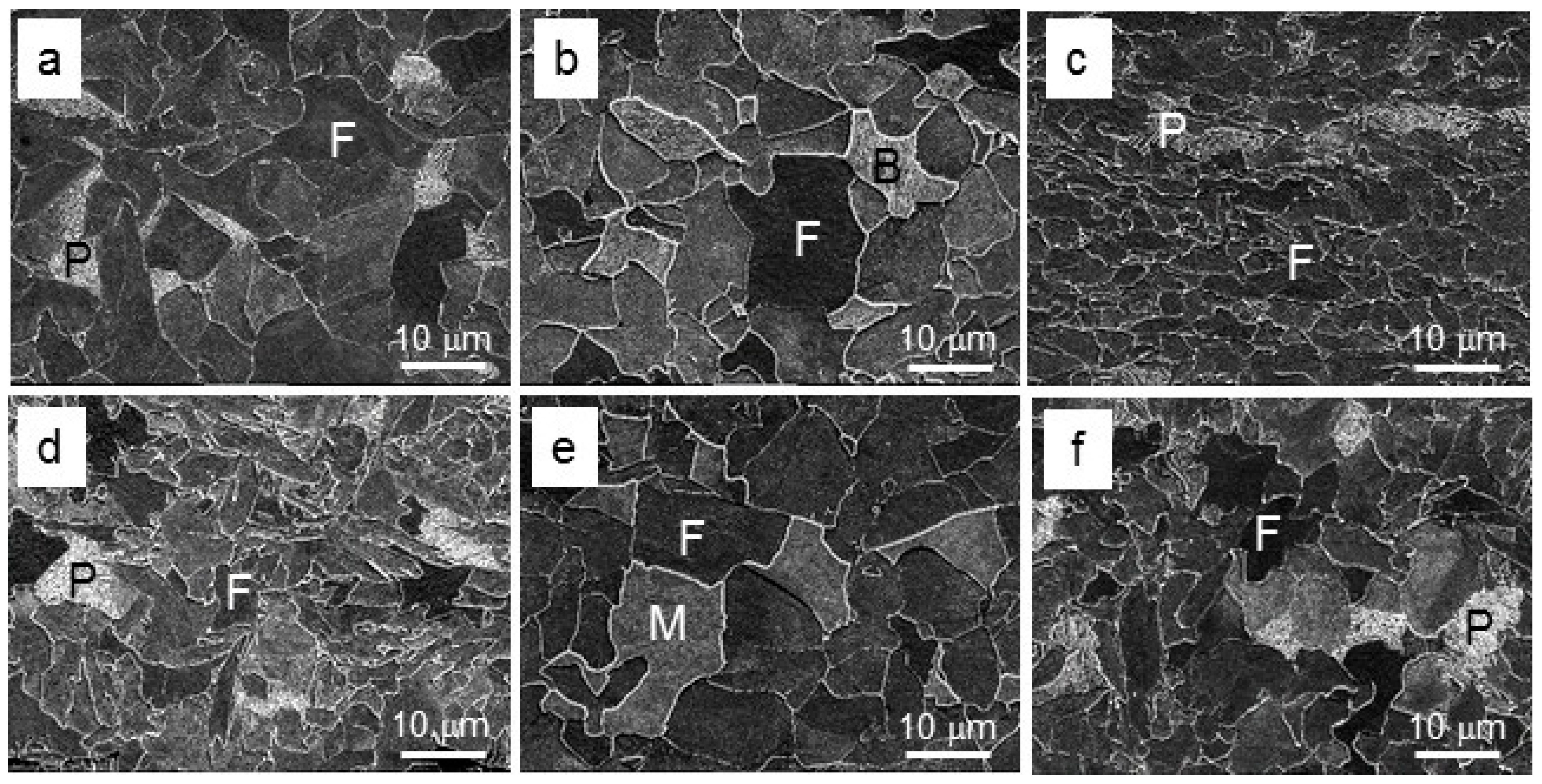
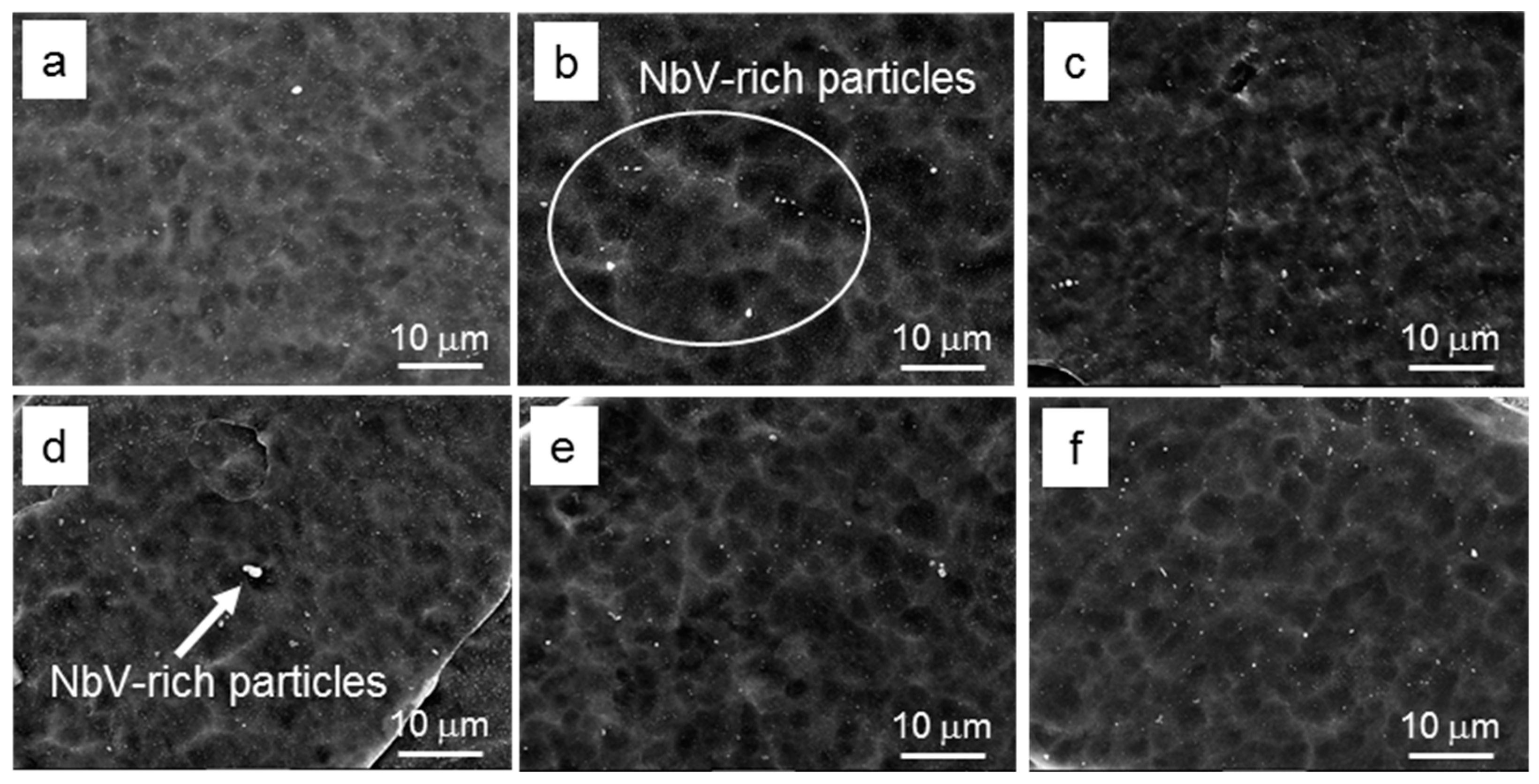
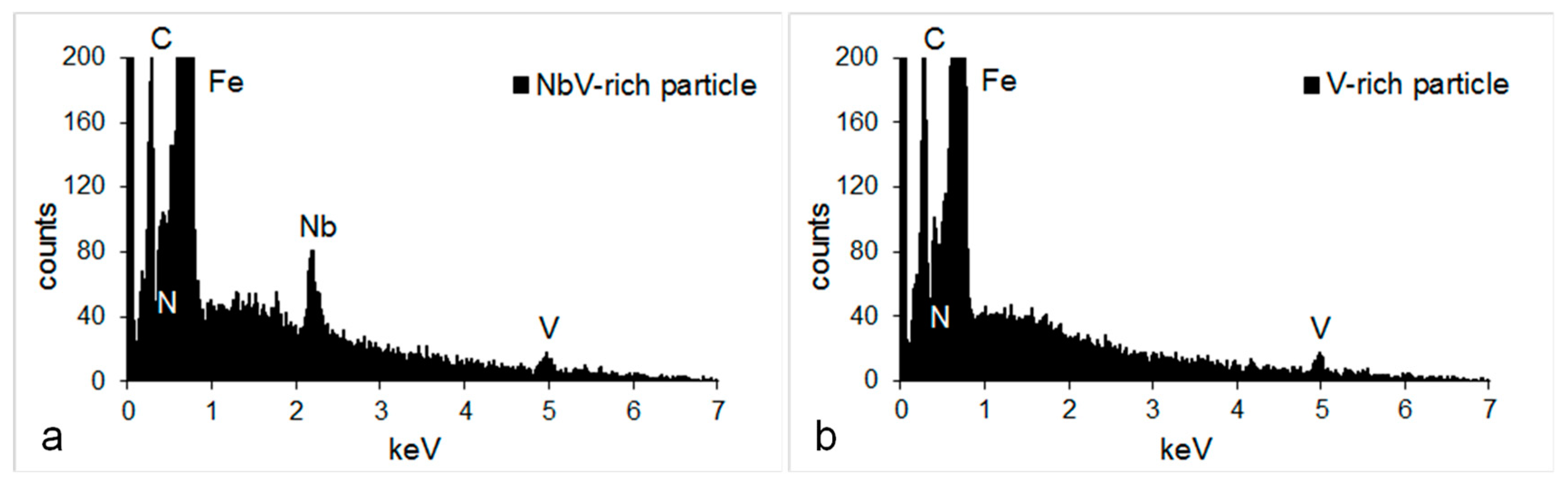
3.1. Effect of Processing on Microstructure

The representative optical (Figure 1) and SEM (Figure 2) micrographs of the microstructure after the TMP show the main phase being polygonal ferrite after all processing schedules. For the same coiling temperature of 600 °C and time of 15 min, the average ferrite grain size has reduced from ~9.5 μm for HFT to ~7 μm for LFT samples (Table 2). A higher coiling temperature of 650 °C for HFT sample resulted in a slight reduction of grain size from ~9.5 μm to ~8.3 μm. The second phase constituted approximately 0.04 area fraction in samples after coiling at 600 °C, whereas after 650 °C holding, it increased to ~0.1 (Table 2). The nature of the second phase also changed from pearlite at lower holding temperature to bainite/martensite at the higher one.
The presence of precipitates with sizes ranging 20–80 nm (Figure 3, Table 2) was evident in ferrite. Their size decreased and number density increased when the finish rolling temperature was reduced. For HFT samples, a higher coiling temperature of 650 °C also produced a finer and more dense distribution of these precipitates compared to 600 °C condition (Table 2). Based on EDS analysis (Figure 4), these particles were identified being NbV-rich and V-rich possibly carbo-nitrides.
TEM analysis revealed the predominant arrangements of fine particles in rows (Figure 5) and some randomly arranged particles between the rows. The diffraction pattern analysis confirmed two types of precipitates (Figure 6 and Figure 7). One of them (denoted as MC, metal carbide, but could be also carbo-nitride) has NaCl-type lattice and exhibits the standard Baker–Nutting orientation relationships (B-N OR) with body centred cubic ferrite lattice (α) [45]:
( 100 ) α / / ( 100 ) MC ,   [ 011 ] α / / [ 010 ] MC ,   [ 0 1 ¯ 1 ] α / / [ 001 ] ) MC
Calculation of the unit cell size gave a = 0.425 nm for these particles, which is in the range of values measured for VC, a = 0.417 [30], VN, a = 0.413 [46], and NbC/NbN, a = 0.436–0.450 [46,47,48]. The second type of precipitates was cementite Fe3C, precipitated randomly between the rows of interphase particles (Figure 7a). Chemical analysis of these interphase precipitates was not carried out in this study. However, the composition of interphase precipitates and fine random precipitates in the same steel composition but after slightly different processing schedule was previously determined using atom probe tomography and EDS in STEM [7,49]. They were found to be (VCrNb)C. The dislocation substructure in ferrite grains is shown in Figure 8. The dislocation number density was the lowest in HFT specimens coiled at 650 °C (Table 2).
As expected, the characteristics of interphase precipitates varied with the TMP schedule (Table 2): (i) for the same HFT, the higher coiling temperature of 650 °C resulted in finer sizes and higher number density (narrower interparticle and intersheet spacings) of interphase precipitates; (ii) for the same coiling conditions, a lower finish deformation temperature led to finer particle sizes and lower number density of interphase precipitates; (iii) particles grew with coiling time; however a possible decrease in number density occurring during coarsening was not observed here. Detailed analysis of these parameters will be provided in Discussion.

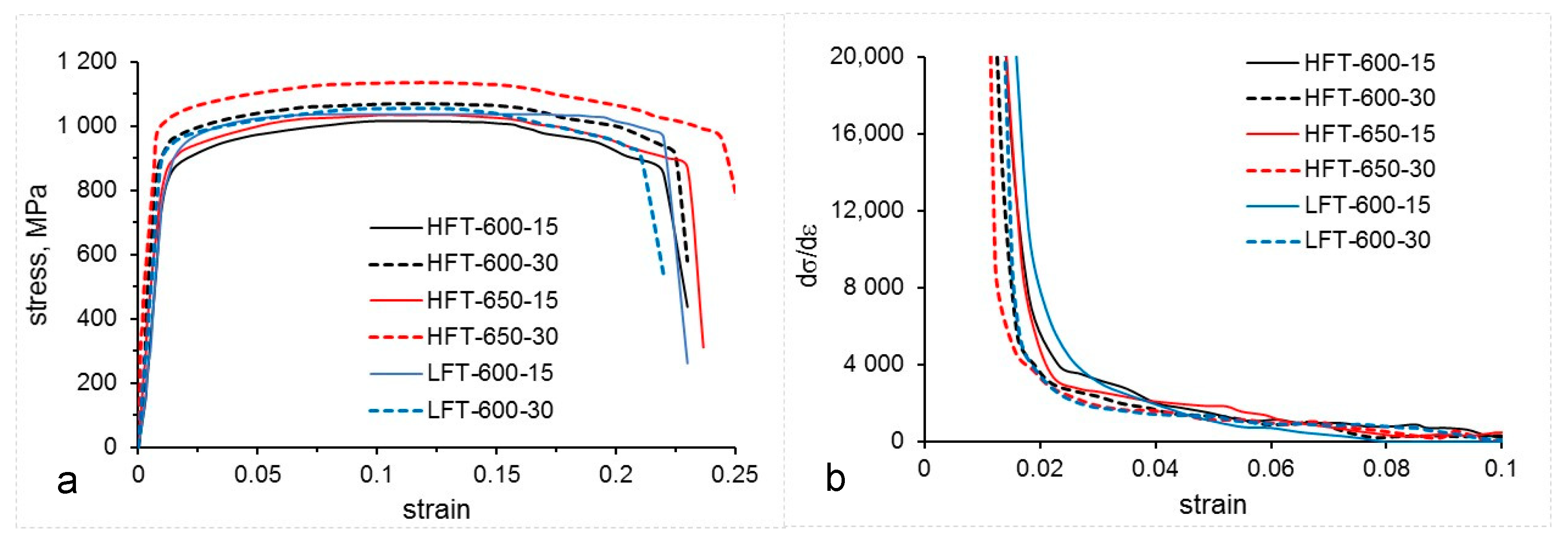
3.2. Effect of Processing on Mechanical Properties

The stress-strain and work hardening rate behaviours are shown in Figure 9. The determined uniaxial tensile properties are listed in Table 2. The stress–strain curves exhibited the continuous yielding behaviour with yield strength (YS) ranging from 870 to 960 MPa, ultimate tensile strength (UTS) from 1030 to 1100 MPa and total elongation from 21 to 25%. The highest strength and elongation were exhibited by steel subjected to HFT/650/30 TMP schedule. However, this was accompanied by the lowest work hardening rate at the early stages of plastic deformation. The overall lowest combination of strength and ductility were in LFT/600/15 and HFT/600/15 conditions. These indicate that a higher finish rolling temperature, a higher coiling temperature and an increased holding time (up to 30 min in this study) provide better mechanical properties.

4. Discussion

4.1. Coiling Temperature

The presence of a high volume fraction of the second phase in the samples coiled at higher temperature indicates that austenite to ferrite transformation was not completed, thus lower temperature phases (bainite or martensite) formed from remaining austenite on cooling to room temperature. Furthermore, as the extent of ferrite formation was less, it also manifested in a smaller ferrite grain size and finer precipitation in HFT/650 samples compared to HFT/600 samples. A smaller ferrite fraction after coiling at a higher temperature of 650 °C could be related to the nose of austenite to ferrite transformation curve being closer to the temperature of 600 °C. In such a case, the ferrite transformation would start earlier during holding at 600 °C compared to 650 °C and proceeded longer, giving more time for the completion of ferrite formation and for the growth of both ferrite grains and interphase precipitates at this temperature. Conditions for the pearlite transformation could also be reached at this temperature as the remaining small amount of austenite is enriched in the rejected from polygonal ferrite carbon. Coiling at higher temperature assisted the rearrangement of dislocations leading to the decrease in their number density.
According to the literature data, the intersheet spacing initially rapidly decreases with decrease in isothermal transformation (coiling) temperature, with much slower decline below 650 °C [34,50]. This trend is due to the complex interplay between the driving forces for ferrite formation and interphase precipitation, and the increased segregation of carbon at γ/α interface at lower temperatures leading to a slower interface mobility [51]. Zhang et al. [51] identified a larger driving force for interphase precipitation as the main factor in their size refinement and density increase. However, they also pointed out that at relatively lower V content, when the driving force for precipitation is relatively small, the growth rate of ferrite may also play a role affecting the characteristics of interphase precipitation. The changes in the interphase precipitation characteristics are also related to the reduction in the diffusivity of alloying elements with decreasing temperature.
In contrast, our observations showed that the intersheet spacing increased from 20 to 28 nm when the temperature was reduced from 650 to 600 °C. Simultaneously, the size of precipitates and interparticle spacing also increased. This could be related to the complex interplay between lower interface mobility at lower temperature and lower diffusion rate of solutes, as well as the lower amounts of solutes available (following a more intense precipitation in austenite after deformation). These require further investigation.

4.2. Finish Deformation Temperature

For the same coiling temperature of 600 °C, the average ferrite grain size and the sizes of all types of particles became finer with a decrease in the finish deformation temperature. The decrease in ferrite grain size could be related to less time being available for recovery processes and austenite grain growth taking place after deformation at 850 °C, compared to 900 °C, as well as the effects on the austenite to ferrite transformation associated with austenite grain size and dislocation sub-structure. The decrease in >20 nm particle sizes can be associated with a larger number of particle nucleation cites on dislocations due to their higher density after the lower finish deformation temperature of 850 °C. The average size of >20 nm precipitates has decreased after extended holding time at 600 °C for both finish deformation temperatures. This could be explained by the growth of all precipitates present and that the originally finer precipitates reached the detectable by SEM size and, thus, shifted the mean size of >20 nm particles to lower values. This correlates with the ~50% increase in total number density of the >20 nm precipitates.
With respect to <20 nm interphase precipitates, the following observations can be highlighted:
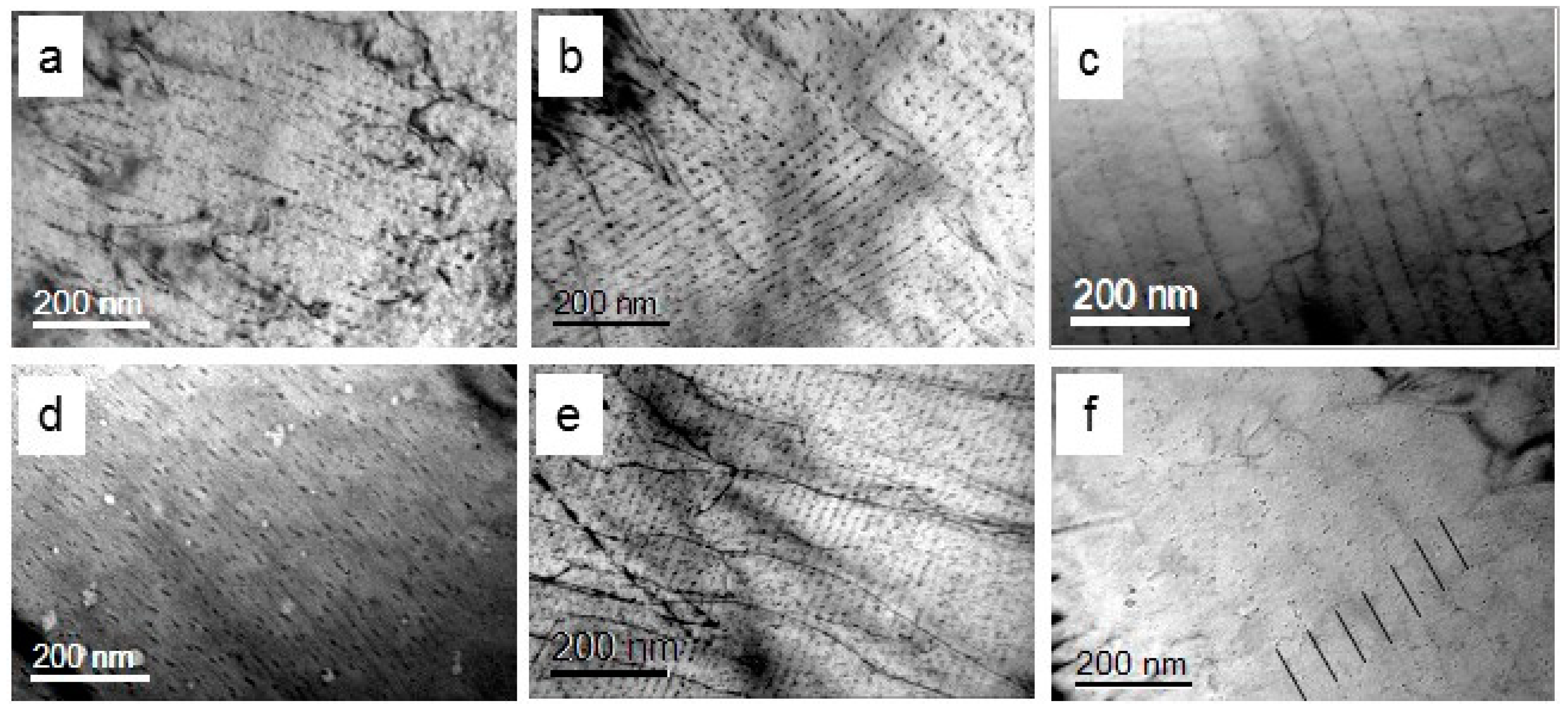
  • intersheet spacing after LFT (55 nm) was twice that after HFT (28 nm) for the same coiling temperature of 600 °C;
  • particle size was 1.7–2.2 times (depending on coiling time) smaller after LFT;
  • growth of these particles during 30 min holding time was slower after LFT (from 3 to 5 nm) than that after HFT (from 5 to 11 nm).
Taking into account the size and number density of coarse precipitates (Table 2), which presumably formed in austenite, it could be suggested that in LFT samples a pronounced strain-induced precipitation depleted the remaining austenite matrix in Nb, V, N, and C. Consequently, there was less solute available for interphase precipitation in LFT condition. This extensive strain-induced precipitation was caused by the deformation temperature of 850 °C being significantly below the non-recrystallisation temperature of 975 °C and approximately at the start of austenite to ferrite transformation. As the increase in driving force for interphase precipitation and the corresponding increase in the number density of precipitates and reduction in intersheet spacing were linked with an increase in V content in steel composition [22,52], our results for LFT and HFT conditions correlate well with the relative amounts of V/Nb remaining in austenite at the start of ferrite formation.

4.3. Holding Time

Extending to 30 min holding time at both temperatures had only a slight effect on the reduction of the second phase fraction but nearly doubled the size of fine precipitates. Furthermore, longer holding time at 650 °C promoted a larger carbon partitioning into remaining austenite increasing its hardenability; therefore, martensite formed instead of bainite after longer holding of 30 min (compare Figure 2b,e). Although the fine precipitates size increased by ~50% with increase of holding time by 15 min, the particles still remained nanosized. The rate of precipitate growth and subsequent coarsening depends on several factors including the amount of solute available, solubility limit, interfacial energy, the diffusion rates of carbide/carbonitride-forming elements and effect of other elements present in solute and multi-component precipitate [19,53]. As the number density of fine precipitates did not vary with an increase in holding time from 15 to 30 min, this indicates that interphase precipitates still undergo growth and not yet coarsening, as during coarsening the number of precipitates decreases. For example, during prolonged isothermal holding, the number density of clusters/fine precipitates gradually decreased with time, whereas their overall coarsening took place accompanied by a significant reduction in their numbers after 100 h [54]. Furthermore, as was reported previously, a significant number of clusters serving as pre-cursors for interphase and random precipitates formation are present in ferrite of microalloyed steels [7,28,31,35,54]. During extended holding time at simulated coiling temperatures, it is expected that these clusters grow and form nanosized precipitates, which will also lead to an increase in the number density of fine precipitates observed in TEM.

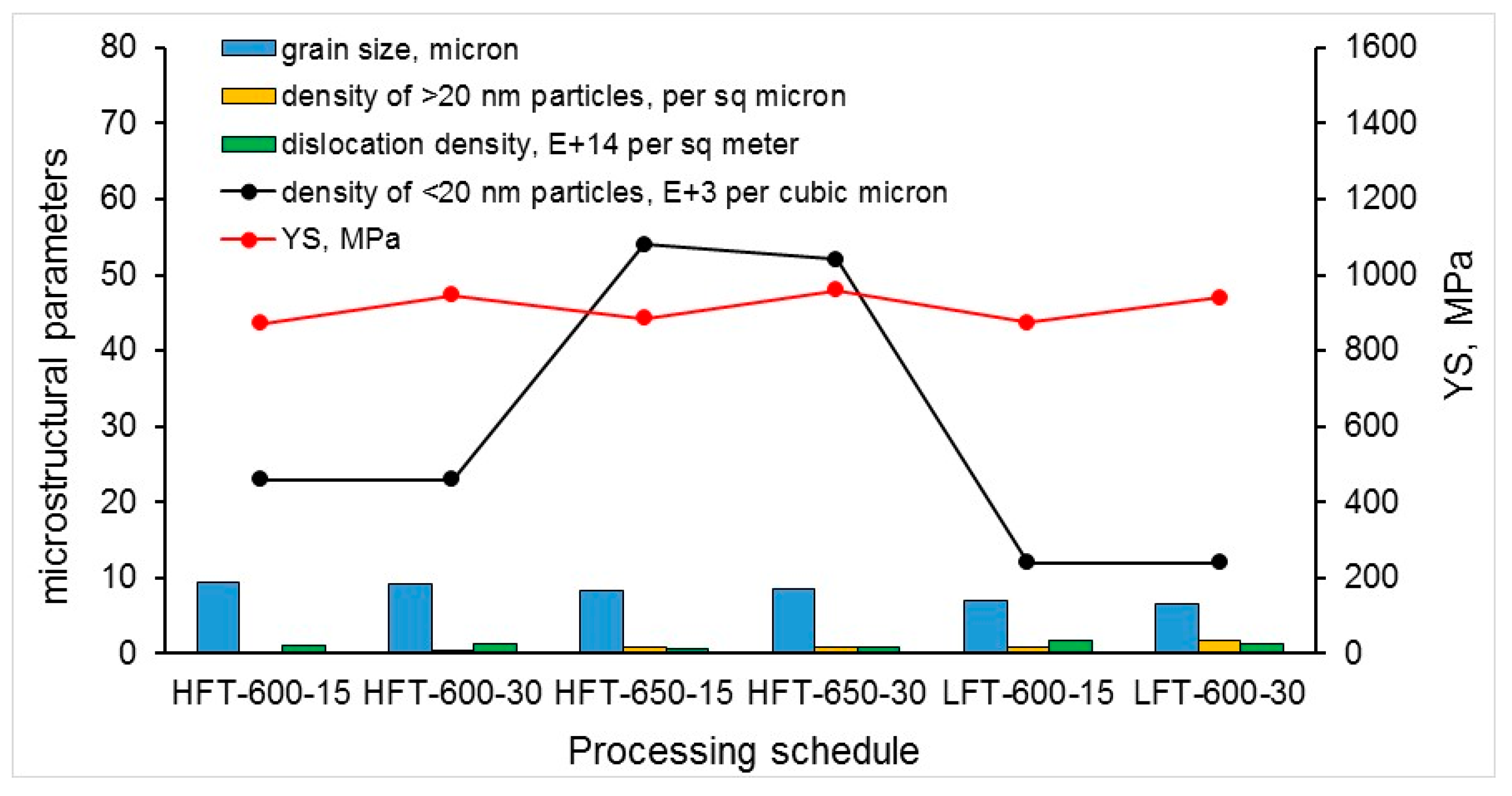
4.4. Mechanical Properties

The tensile properties rely on the contributions from the range of microstructural features: ferrite grain size, dislocation density (including local pile-ups around the second phase grains), solute concentrations in ferrite, clustering, and precipitation.
Thus, for the same coiling temperature of 600 °C, both HFT and LFT samples displayed similar YS and UTS values (Table 2, Figure 10), with only slightly lower total elongation for the LFT condition. However, for the LFT conditions the ferrite grain size was 26–29% smaller, the number density of >20 nm particles was 3.9–5.1 times higher, the number density of <20 nm particles was 50% lower, the dislocation density was similar, and the matrix unit cell size (indicative of the solid solute concentrations) was also similar.
For the same finishing deformation temperature of HFT, the higher coiling temperature of 650 °C resulted in 13–14 MPa higher YS, up to 25 MPa higher UTS, and similar elongation. However, for the higher coiling temperature, the ferrite grain size was 13% smaller, the number density of >20 nm particles was 2.7–4 times higher, the number density of <20 nm particles was 2.3 times higher, and the dislocation density was only slightly lower. This indicates a generally positive contribution of increased coiling temperature on properties, although the effect of precipitation strengthening was not proportional.
An increase in holding time (from 15 to 30 min) at the same coiling temperature brought a substantial increase in strength (by 65–75 MPa YS and 20–70 MPa UTS). This corresponds to the only major change in microstructure, which is the growth of <20 nm particles, leading to an increase in their volume fraction. This supports the effect of a single particle size on the precipitation strengthening contribution to mechanical properties: in the case of a similar number density, larger nanosized particles (5–11 nm) are preferable. In addition to the growth of interphase precipitates, longer holding time stimulates (i) transition of solute atoms into atom clusters, (ii) evolution of pre-existing atom clusters into very fine nano-sized precipitates (not observed here with TEM but reported previously [7,28,31]), and (iii) nucleation and growth of random precipitates if a sufficient amount of solute atoms was left unconsumed by the interphase precipitation.
Overall, the microstructure–properties analysis indicated an absence of a particular microstructural parameter that was predominantly responsible for the mechanical properties formation. To achieve the desired combination of mechanical properties, the TMP schedule should aim to maximise the strengthening contributions from all the microstructural features.

5. Conclusions

The investigation of the effect of TMP parameters on microstructure and tensile properties of newly designed CrVNb-containing microalloyed steel led to the following conclusions:
  • Lower finish deformation temperature resulted in finer ferrite microstructure with a higher number density of >20 nm strain-induced precipitates, compared to the higher finish deformation temperature.
  • Interphase precipitation occurred under all processing conditions but with various characteristics. For the same coiling temperature, the intersheet spacing decreased when the deformation was finished at a higher temperature. This was associated with more solute present (lower volume fraction of >20 nm particles) in austenite at the start of austenite to ferrite transformation.
  • Reduction in simulated coiling temperature led to unexpected increase in intersheet and interparticle spacing, which requires further investigation.
  • The increase in volume fraction of interphase precipitates due to their growth during extended holding time to 30 min at simulated coiling temperatures was responsible for the observed strength increment of up to 75 MPa.

Author Contributions

Conceptualization, E.P. and C.K.; methodology, A.K.; investigation, A.K.; Data analysis, A.K. and E.P.; writing—original draft preparation, A.K. and E.P.; writing—review and editing, E.P. and C.K.; project administration, E.P.; funding acquisition, E.P. and C.K. All authors have read and agreed to the published version of the manuscript.

Funding

This research was funded by the Australian Research Council (ARC) Research Hub for Australian Steel Manufacturing under the Industrial Transformation Research Hubs scheme (Project ID: IH130100017). The microscopy was carried out using JEOL JSM-7001F FEGSEM (supported by ARC grant LE0882613) and JEOL JEM-2011 TEM (supported by ARC grant LE0237478) microscopes at the Electron Microscopy Centre at the University of Wollongong.

Data Availability Statement

The data presented in this study are available on request from the corresponding author.

Conflicts of Interest

The authors declare no conflict of interest.

References

  1. Batte, A.D.; Honeycombe, R.W.K. Strengthening of ferrite by vanadium carbide precipitation. Met. Sci. J. 1973, 7, 160–168. [Google Scholar] [CrossRef]
  2. Funakawa, Y.; Shiozaki, T.; Tomita, K.; Yamamoto, T.; Maeda, E. Development of High Strength Hot-rolled Sheet Steel Consisting of Ferrite and Nanometer-sized Carbides. ISIJ Int. 2004, 44, 1945–1951. [Google Scholar] [CrossRef]
  3. Baker, T.N. Microalloyed steels. Ironmak. Steelmak. 2016, 43, 264–307. [Google Scholar] [CrossRef] [Green Version]
  4. Baker, T.N. Processes, microstructure and properties of vanadium microalloyed steels. Mater. Sci. Technol. 2009, 25, 1083–1107. [Google Scholar] [CrossRef] [Green Version]
  5. Funakawa, Y.; Fujita, T.; Yamada, K. Metallurgical Features of Nanohiten™ and Application to Warm Stamping; JFE: Tokyo, Japan, 2013; pp. 74–79. [Google Scholar]
  6. Kamikawa, N.; Abe, Y.; Miyamoto, G.; Funakawa, Y.; Furuhara, T. Tensile Behavior of Ti, Mo-added Low Carbon Steels with Interphase Precipitation. ISIJ Int. 2014, 54, 212–221. [Google Scholar] [CrossRef] [Green Version]
  7. Singh, N.; Casillas, G.; Wexler, D.; Killmore, C.; Pereloma, E. Application of advanced experimental techniques to elucidate the strengthening mechanisms operating in microalloyed ferritic steels with interphase precipitation. Acta Mater. 2020, 201, 386–402. [Google Scholar] [CrossRef]
  8. Davenport, A.T.; Berry, F.G.; Honeycombe, R.W.K. Interphase Precipitation in Iron Alloys. Met. Sci. J. 1968, 2, 104–106. [Google Scholar] [CrossRef]
  9. Davenport, A.T.; Honeycombe, R.W.K. Precipitation of Carbides at γ-α Boundaries in Alloy Steels. Proc. R. Soc. A Math. Phys. Eng. Sci. 1971, 322, 191–205. [Google Scholar]
  10. Barbacki, A.; Honeycombe, R.W.K. Transitions in carbide morphology in molybdenum and vanadium steels. Metallography 1976, 9, 277–291. [Google Scholar] [CrossRef]
  11. Ricks, R.; Howell, P. The formation of discrete precipitate dispersions on mobile interphase boundaries in iron-base alloys. Acta Metall. 1983, 31, 853–861. [Google Scholar]
  12. Deardo, A.J. Niobium in modern steels. Int. Mater. Rev. 2003, 48, 371–402. [Google Scholar] [CrossRef]
  13. Kestenbach, H.J. Dispersion hardening by niobium carbonitride precipitation in ferrite. Mater. Sci. Technol. 1997, 13, 731–739. [Google Scholar] [CrossRef]
  14. Kestenbach, H.J.; Gallego, J. On dispersion hardening of microalloyed hot strip steels by carbonitride precipitation in austenite. Scr. Mater. 2001, 44, 791–796. [Google Scholar] [CrossRef]
  15. Morrison, W.B.; Woodhead, J.H. Influence of small niobium additions on mechanical properties of commercial mild steels. J. Iron Steel Inst. 1963, 201, 317–325. [Google Scholar]
  16. Kestenbach, H.J.; Campos, S.S.; Morales, E.V. Role of interphase precipitation in microalloyed hot strip steels. Mater. Sci. Technol. 2006, 22, 615–626. [Google Scholar] [CrossRef]
  17. Tsai, S.-P.; Jen, C.-H.; Yen, H.-W.; Chen, C.-Y.; Tsai, M.-C.; Huang, C.-Y.; Wang, Y.-T.; Yang, J.-R. Effects of interphase TiC precipitates on tensile properties and dislocation structures in a dual phase steel. Mater. Charact. 2017, 123, 153–158. [Google Scholar] [CrossRef]
  18. Tsai, S.-P.; Su, T.-C.; Yang, J.-R.; Chen, C.-Y.; Wang, Y.-T.; Huang, C.-Y. Effect of Cr and Al additions on the development of interphase-precipitated carbides strengthened dual-phase Ti-bearing steels. Mater. Des. 2017, 119, 319–325. [Google Scholar] [CrossRef]
  19. Balliger, N.K.; Honeycombe, R.W.K. The effect of nitrogen on precipitation and transformation kinetics in vanadium steels. Metall. Trans. A 1980, 11, 421–429. [Google Scholar] [CrossRef]
  20. Miyamoto, G.; Hori, R.; Poorganji, B.; Furuhara, T. Crystallographic analysis of proeutectoid ferrite/austenite interface and interphase precipitation of vanadium carbide in medium-carbon steel. Metall. Mater. Trans. A 2013, 44, 3436–3443. [Google Scholar] [CrossRef] [Green Version]
  21. Chen, M.Y.; Gouné, M.; Verdier, M.; Bréchet, Y.; Yang, J.R. Interphase precipitation in vanadium-alloyed steels: Strengthening contribution and morphological variability with austenite to ferrite transformation. Acta Mater. 2014, 64, 78–92. [Google Scholar] [CrossRef]
  22. Zhang, Y.J.; Miyamoto, G.; Shinbo, K.; Furuhara, T. Quantitative measurements of phase equilibria at migrating α/γ interface and dispersion of VC interphase precipitates: Evaluation of driving force for interphase precipitation. Acta Mater. 2017, 128, 166–175. [Google Scholar] [CrossRef]
  23. Miyamoto, G.; Hori, R.; Poorganji, B.; Furuhara, T. Interphase precipitation of VC and resultant hardening in V-added medium carbon steels. ISIJ Int. 2011, 51, 1733–1739. [Google Scholar] [CrossRef] [Green Version]
  24. Yen, H.W.; Chen, P.Y.; Huang, C.Y.; Yang, J.R. Interphase precipitation of nanometer-sized carbides in a titanium–molybdenum-bearing low-carbon steel. Acta Mater. 2011, 59, 6264–6274. [Google Scholar]
  25. Yen, H.-W.; Huang, C.-Y.; Yang, J.-R. Characterization of interphase-precipitated nanometer-sized carbides in a Ti-Mo-bearing steel. Scr. Mater. 2009, 61, 616–619. [Google Scholar] [CrossRef]
  26. Mukherjee, S. Nanoscale Precipitation in Advanced High Strength Steels. Ph.D. Thesis, Deakin University, Geelong, Australia, 2012. [Google Scholar]
  27. Mukherjee, S.; Timokhina, I.B.; Zhu, C.; Ringer, S.P.; Hodgson, P.D. Three-dimensional atom probe microscopy study of interphase precipitation and nanoclusters in thermomechanically treated titanium–molybdenum steels. Acta Mater. 2013, 61, 2521–2530. [Google Scholar]
  28. Wang, J.; Weyland, M.; Bikmukhametov, I.; Miller, M.K.; Hodgson, P.D.; Timokhina, I. Transformation from cluster to nano-precipitate in microalloyed ferritic steel. Scr. Mater. 2019, 160, 53–57. [Google Scholar] [CrossRef]
  29. Jang, J.H.; Heo, Y.-U.; Lee, C.-H.; Bhadeshia, H.K.D.H.; Suh, D.-W. Interphase precipitation in Ti-Nb and Ti-Nb-Mo bearing steel. Mater. Sci. Technol. 2013, 29, 309–313. [Google Scholar]
  30. Jang, J.H.; Lee, C.-H.; Heo, Y.-U.; Suh, D.-W. Stability of (Ti,M)C (M=Nb, V, Mo and W) carbide in steels using first-principles calculations. Acta Mater. 2012, 60, 208–217. [Google Scholar] [CrossRef]
  31. Dhara, S.; Marceau, R.K.W.; Wood, K.; Dorin, T.; Timokhina, I.B.; Hodgson, P.D. Precipitation and clustering in a Ti-Mo steel investigated using atom probe tomography and small-angle neutron scattering. Mater. Sci. Eng. A 2018, 718, 74–86. [Google Scholar] [CrossRef]
  32. Bu, F.Z.; Wang, X.M.; Yang, S.W.; Shang, C.J.; Misra, R.D.K. Contribution of interphase precipitation on yield strength in thermomechanically simulated Ti–Nb and Ti–Nb–Mo microalloyed steels. Mater. Sci. Eng. A 2015, 620, 22–29. [Google Scholar] [CrossRef]
  33. Pereloma, E.; Timokhina, I. Clustering and Precipitation in Ferritic Microalloyed Steels. In Reference Module in Materials Science and Materials Engineering; Elsevier: Amsterdam, The Netherlands, 2020. [Google Scholar] [CrossRef]
  34. Xiong, Z.; Timokhina, I.; Pereloma, E. Clustering, nano-scale precipitation and strengthening of steels. Prog. Mater. Sci. 2020, 100764, in press. [Google Scholar] [CrossRef]
  35. Bikmukhametov, I.; Beladi, H.; Wang, J.; Hodgson, P.D.; Timokhina, I. The effect of strain on interphase precipitation characteristics in a Ti-Mo steel. Acta Mater. 2019, 170, 75–86. [Google Scholar] [CrossRef]
  36. Smith, R.M.; Dunne, D. Structural aspects of alloy carbonitride precipitation in microalloyed steels. Mater. Forum 1988, 11, 166–181. [Google Scholar]
  37. Li, C.-N.; Li, X.-L.; Yuan, G.; Misra, R.D.K.; Kang, J.; Wang, G.-D. Precipitation behavior and mechanical properties of a hot rolled Ti-bearing dual phase steel. Mater. Sci. Eng. A 2016, 673, 213–221. [Google Scholar] [CrossRef] [Green Version]
  38. Gong, P.; Liu, X.G.; Rijkenberg, A.; Rainforth, W.M. The effect of molybdenum on interphase precipitation and microstructures in microalloyed steels containing titanium and vanadium. Acta Mater. 2018, 161, 374–387. [Google Scholar] [CrossRef] [Green Version]
  39. Okamoto, R.; Borgenstam, A.; Ågren, J. Interphase precipitation in niobium-microalloyed steels. Acta Mater. 2010, 58, 4783–4790. [Google Scholar]
  40. Iza-Mendia, A.; Altuna, M.A.; Pereda, B.; Gutiérrez, I. Precipitation of Nb in Ferrite After Austenite Conditioning. Part I: Microstructural Characterization. Metall. Mater. Trans. A 2012, 43, 4553–4570. [Google Scholar] [CrossRef]
  41. Chen, C.Y.; Chen, C.C.; Yang, J.R. Microstructure characterization of nanometer carbides heterogeneous precipitation in Ti-Nb and Ti-Nb-Mo steel. Mater. Charact. 2014, 88, 69–79. [Google Scholar]
  42. Mukherjee, S.; Timokhina, I.; Zhu, C.; Ringer, S.P.; Hodgson, P.D. Clustering and precipitation processes in a ferritic titanium-molybdenum microalloyed steel. J. Alloys Compd. 2017, 690, 621–632. [Google Scholar]
  43. Charleux, M.; Poole, W.J.; Militzer, M.; Deschamps, A. Precipitation behavior and its effect on strengthening of an HSLA-Nb/Ti steel. Metall. Mater. Trans. A 2001, 32, 1635–1647. [Google Scholar]
  44. Kostryzhev, A.; Singh, N.; Chen, L.; Killmore, C.; Pereloma, E. Comparative effect of Mo and Cr on microstructure and mechanical properties in NbV-microalloyed bainitic steels. Metals 2018, 8, 134. [Google Scholar] [CrossRef] [Green Version]
  45. Baker, R.G.; Nutting, J. The tempering of a Cr-Mo-V-W and a Mo-V steel in precipitation processes in steels. Iron Steel Inst. Spec. Rep. 1959, 64, 1–22. [Google Scholar]
  46. Fors, D.H.R.; Wahnström, G. Theoretical study of interface structure and energetics in semicoherent Fe(001)/MX(001) systems (M=Sc, Ti, V, Cr, Zr, Nb, Hf, Ta; X=C or N). Phys. Rev. B 2010, 82, 195410. [Google Scholar] [CrossRef] [Green Version]
  47. Morales, E.V.; Gallego, J.; Kestenbach, H.J. On coherent carbonitride precipitation in commercial microalloyed steels. Philos. Mag. Lett. 2003, 83, 79–87. [Google Scholar] [CrossRef]
  48. Tirumalasetty, G.K.; van Huis, M.A.; Fang, C.M.; Xu, Q.; Tichelaar, F.D.; Hanlon, D.N.; Sietsma, J.; Zandbergen, H.W. Characterization of NbC and (Nb,Ti)N nanoprecipitates in TRIP assisted multiphase steels. Acta Mater. 2011, 59, 7406–7415. [Google Scholar] [CrossRef] [Green Version]
  49. Pereloma, E.; Cortie, D.; Singh, N.; Casillas, G.; Niessen, F. Uncovering the mechanism of dislocation interaction with nanoscale (<4 nm) interphase precipitates in microalloyed ferritic steels. Mater. Res. Lett. 2020, 8, 341–347. [Google Scholar]
  50. Zhang, Y.J.; Miyamoto, G.; Shinbo, K.; Furuhara, T.; Ohmura, T.; Suzuki, T.; Tsuzaki, K. Effects of transformation temperature on VC interphase precipitation and resultant hardness in low-carbon steels. Acta Mater. 2015, 84, 375–384. [Google Scholar] [CrossRef]
  51. Zhang, Y.J.; Miyamoto, G.; Shinbo, K.; Furuhara, T. Weak influence of ferrite growth rate and strong influence of driving force on dispersion of VC interphase precipitation in low carbon steels. Acta Mater. 2020, 186, 533–544. [Google Scholar] [CrossRef]
  52. Lagneborg, R.; Zajac, S. A model for interphase precipitation in V-microalloyed structural steels. Metall. Mater. Trans. A 2001, 32, 39–50. [Google Scholar] [CrossRef]
  53. Gleiter, H. Microstructure. In Physical Metallurgy; Cahn, R.W., Haasen, P., Eds.; Elsevier: Amstredam, The Netherlands, 1996; pp. 844–942. [Google Scholar]
  54. Bikmukhametov, I. Investigation of Clusters and Nano-particles in Thermomechanically Processed Ti-Mo Steel. Ph.D. Thesis, Deakin University, Geelong, Australia, 2019. [Google Scholar]
Figure 1. Optical images of microstructures for studied conditions: (a) HFT/600/15, (b) HFT/650/15, (c) LFT/600/15, (d) HFT/600/30, (e) HFT/650/30, (f) LFT/600/30.
Metals 11 00107 g001
Figure 2. SEM images of microstructures showing the phase balance: (a) HFT/600/15, (b) HFT/650/15, (c) LFT/600/15, (d) HFT/600/30, (e) HFT/650/30, (f) LFT/600/30.
Metals 11 00107 g002
Figure 3. SEM images of ferrite grains showing the Nb- and V-rich particles: (a) HFT/600/15, (b) HFT/650/15, (c) LFT/600/15, (d) HFT/600/30, (e) HFT/650/30, (f) LFT/600/30.
Metals 11 00107 g003
Figure 4. Typical SEM-EDS spectra of >20 nm (a) NbV-rich and (b) V-rich particles.
Metals 11 00107 g004
Figure 5. TEM bright field images of precipitate arrangements in ferrite: (a) HFT/600/15, (b) HFT/650/15, (c) LFT/600/15, (d) HFT/600/30, (e) HFT/650/30, (f) LFT/600/30.
Metals 11 00107 g005
Figure 6. TEM diffraction patterns used to determine the type of precipitates in the <15 nm size range: (a) HFT/600/15, (b) HFT/650/15, (c) LFT/600/15, (d) HFT/600/30, (e) HFT/650/30, (f) LFT/600/30.
Metals 11 00107 g006
Figure 7. Analysis of the diffraction patterns characteristic for the studied steel in all processing conditions: (a) Fe3C and (b) NbV-rich carbide.
Metals 11 00107 g007
Figure 8. Selected TEM bright field images of dislocation substructure in ferrite after 15 min simulated coiling: (a) HFT/600, (b) HFT/650 and (c) LFT/600.
Metals 11 00107 g008
Figure 9. (a) Stress–strain curves and (b) work hardening rate for the studied steel.
Metals 11 00107 g009
Figure 10. Variations in microstructural parameters and the yield stress with processing schedule.
Metals 11 00107 g010
Table 2. Microstructural parameters and mechanical properties in the studied steel.
ParametersHFTLFT
600/15600/30650/15650/30600/15600/30
Average ferrite grain size, μm9.5 ± 4.79.3 ± 4.18.3 ± 3.98.5 ± 4.07.0 ± 3.06.6 ± 2.9
Second phase fraction0.040.030.110.100.040.04
>20 nm particles
(SEM)
Average size, nm48 ± 2442 ± 1933 ± 1632 ± 1630 ± 1327 ± 9
Number density, μm−20.220.320.880.880.851.65
Area fraction0.00050.00050.00090.00090.00070.0011
Chemistry27%
NbV
50% NbV
20% V
100%
NbV
50% NbV
50% V
60% NbV
30% V
60% NbV
40% V
<20 nm particles
(TEM)
Average size, nm5 ± 211 ± 23 ± 15 ± 13 ± 15 ± 1
Interparticle spacing, nm22 ± 522 ± 712 ± 212 ± 422 ± 422 ± 5
Intersheet spacing, nm28 ± 928 ± 720 ± 521 ± 255 ± 1155 ± 15
Number density, ×103 μm−3232354521212
Volume fraction0.00150.01610.00080.00340.00020.0008
Chemistry(VCrNb)C
Dislocation density, ×1014 m−21.1 ± 0.21.2 ± 0.10.7 ± 0.10.8 ± 0.11.8 ± 0.21.2 ± 0.1
YS, MPa872 ± 50946 ± 15885 ± 35960 ± 20875 ± 45940 ± 20
UTS, MPa1030 ± 301075 ± 201030 ± 301100 ± 201035 ± 151055 ± 10
Elongation, %23 ± 223 ± 223 ± 325 ± 221 ± 321 ± 2
Publisher’s Note: MDPI stays neutral with regard to jurisdictional claims in published maps and institutional affiliations.

