Article

Effects of Fe11+ Ions Irradiation on the Microstructure and Performance of Selective Laser Melted 316L Austenitic Stainless Steels

College of Materials Science and Technology, Nanjing University of Aeronautics and Astronautics, Nanjing 211106, China
*
Author to whom correspondence should be addressed.
Metals 2020, 10(9), 1140; https://doi.org/10.3390/met10091140
Submission received: 21 June 2020 / Revised: 4 August 2020 / Accepted: 13 August 2020 / Published: 24 August 2020

Abstract

:
The effect of irradiation temperature on the microstructure, hardness, and corrosion resistance of 316L stainless steels (SS) fabricated by the selective laser melting (SLM) process was investigated to further understand the radiation degradation of the additive manufactured steels. The Transmission Electron Microscopy (TEM) results confirmed the cellular sub-grains and the high-density dislocation networks present in the SLM formed 316L SS. After exposing samples to Fe11+ ions irradiation till 1 dpa at room temperature, the ultra-fine sub-grain structure maintains its configuration, but the dislocations were observed expanding from the vicinity of the sub-grain boundaries into the grains. In contrast, the expanding phenomenon of dislocations was insignificant in samples irradiated at 450 °C. The average size of dislocation loops increased from 6 to 8.5 nm when the irradiation temperature increased, with the number density decreased from 2.7 × 10²²/m3 to 1.3 × 10²²/m3. This study reveals that the reduced dislocation loop density and distribution region caused by the improved temperature will suppress the radiation hardening and corrosion of SLM 316L SSs.

1. Introduction

Austenitic 316L stainless steels (SS) have been widely used as structural materials in nuclear reactors because of their excellent corrosion resistance, mechanical properties, and formability [1,2,3]. Selective laser meting (SLM) is a rapidly developing additive manufacturing (AM) technique used in metal alloys, with full freedom for designing, short time for production, and low economic cost, which is particularly suitable for fabricating the complex components used in nuclear reactors, such as advanced heat exchangers and spray nozzles [4,5,6]. In recent years, several studies have been conducted on the fabrication process, microstructure, mechanical properties, and corrosion resistance for SLM 316L SS used in reactors, and numerous tests have demonstrated the excellent performance of this steel type for various applications [7,8,9,10,11,12,13].
Despite its many benefits, however, the 316L SS used in reactors will suffer long-term irradiation, which could lead to radiation defects, radiation hardening, radiation-induced solution, and degradation of corrosion resistance [14,15,16,17]. These radiation effects bring about microstructural and property changes, thereby accelerating the failure of materials. A large number of studies have been conducted to determine the radiation effects on traditional 316L SS. Jin et al. [18] observed the distribution of dislocation loops in 316L SS specimens using transmission electron microscopy (TEM) and clarified the effect of irradiation dose and temperature on the dislocation loops. Nanoindentation and potentiodynamic polarization tests have respectively been used to evaluate the mechanical and corrosion resistance properties of post-irradiated 316L SS by Jiao et al. [19]. The radiation effect on 316L SS prepared via the traditional process has been widely studied, and a considerable amount of experimental data are available for various engineering applications. However, the irradiation effect on SLM 316L SS is still unknown and has rarely been researched. In previous work, Sun et al. performed the He ions irradiation experiments at 450 °C to demonstrate the internal effects of the microstructure on bubbles distribution and hardness of SLM 316L SS [20]. Song et al. [21] performed Fe ions irradiation experiments at 360 °C to study the irradiation-induced microstructure and irradiation-assisted stress corrosion cracking (IASCC) behavior of AM 316L SS; the authors found that the hot-isotropic pressing (HIP) method could enhance the radiation tolerance and IASCC performance of the AM specimens. Considering the complexity of radiation environments in reactors, the effect of irradiation on SLM 316L SS has yet to be explored. The effects of irradiation temperature on the microstructure, hardness, and corrosion resistance are likely to pose additional challenges to engineering applications.
This work aims to determine the influence of irradiation temperature on the microstructural and property changes in SLM 316L SS. In this study, we performed Fe ions irradiation experiments with a dose of 1 dpa at room temperature (RT) and 450 °C. The evolution of microstructure, hardness, and corrosion resistance of steel samples were then investigated by TEM, grazing incidence X-ray diffraction (GIXRD), and nanoindentation and potentiodynamic polarization tests.

2. Experimental Methods

2.1. Materials Fabrication

In this work, a 5 × 3 × 3 cm3 cuboid segment of a 316L SS sample was printed from nitrogen gas-atomized spherical 316L steel powder via the SLM process using a BLT-S300 facility (Bright Laser Technologies Co., Xian, China). The commercially available powder (AMC powders Co., Beijing, China) used in this experiment has a particle size of 15–53 μm, and the following chemical composition in (wt.%): 0.017 C, 17.17 Cr, 10.45 Ni, 2.22 Mo, 1.20 Mn, 0.52 Si, 0.014 S, 0.0315 P, and Fe balance. The process parameters were optimized to achieve denser samples. The laser power was fixed to 250 W. No preheating was applied to the building platform. The scan speed and line spacing were set as 850 mm/s and 0.1 mm, respectively. The thickness of each layer was 0.04 mm. After forming, the sheet samples with a dimension of 1 × 1 × 0.05 cm3 for the irradiation experiments and other characterization processes were cut from the SLM 316L SS sample by wire cutting, ground with various grades of SiC papers, and then mechanically polished to obtain a mirror finish.

2.2. Irradiation Process

Ion irradiation experiments were performed on the 320 kV high-voltage platform at the Institute of Modern Physics, Chinese Academy of Science (CAS). The samples were irradiated by 3 MeV Fe11+ ions with a fluence of 0.94 × 10¹⁵ ions/cm2 at RT and 450 °C (roughly 0.45 Tm of 316L SS). Since iron is the main element in 316L SS, Fe ions irradiation avoids the negative impact by introducing impurities during the irradiation process and hence is closer to the actual neutron irradiation environment. During the radiation process, the beam area was approximately 1.8 × 2 cm2, the average beam current was 1.4 μA, and the temperatures were maintained within ±10 °C for each radiation condition. Figure 1 shows the depth profiles of damage events in the samples under a series of Fe ions irradiation conditions calculated by SRIM [22]. The depth of the peak damage level is approximately 880 nm. According to the results of SRIM, the irradiation damage rate is 2.35 × 10⁻⁴ dpa/s and the total irradiation damage can reach 1 dpa, which corresponds to the irradiation damage after one year in the reactors [23]. In this work, we studied the behaviors of 316L SS at 450 °C because the irradiation damage at this temperature region is the most significant according to previous studies [24].

2.3. Characterization Methods

To identify the phase structures of pre- and post-irradiated samples, grazing incidence X-ray diffraction (GIXRD) with CuKα (λ = 1.54 Å) radiation was used with the incident angle fixed at 1°. Various TEM (Tecnai G2 F20 S-Twin, Suzhou, China) techniques were used to examine the grain structure and dislocation loops of the samples at an operating voltage of 200 kV. The pre-irradiated samples were prepared for TEM using the standard double-jet procedure (MTPA-5, Shanghai Jiaotong University). To investigate the microstructure of post-irradiated samples, cross sectional TEM foils were prepared via the focused ion beam method (FIB, FEI Helios Nanolab 600, Shanghai, China). The thickness of FIB foils was set to 100 nm. For each sample, ten TEM pictures at different region were used to determine the dislocation density. Provided the thickness of TEM foil is regarded as 100 nm approximately, the dislocation density was obtained using the dislocation loop number to divide the product of the picture area and foil thickness.
Hardness tests were performed using the Nano Indenter G200 (Agilent, Suzhou, China) with a Berkovich-type indenter [25]. The continuous stiffness measurement technique with a maximum indentation depth setting at 1250 nm was used for the pre- and post-irradiated samples [26]. The indents were spaced 30 μm apart, and over five indents were applied to each sample.
The potentiodynamic polarization tests were performed using a standard three-electrode cell with a platinum grid as the counter electrode and saturated calomel electrode (SCE) as the potential reference. The tests were conducted in NaCl (0.9 wt.%) solution at 25 °C. The samples were soaked for 1 h in NaCl solution, then the potentiodynamic polarization tests were carried out at a scan rate of 1 mV/s when a fairly stable potential could be obtained. The electrode potential performed with a variation of voltage of −700 mV to 800 mV.

3. Results and Discussion

3.1. Microstructure of Pre–Irradiated Samples

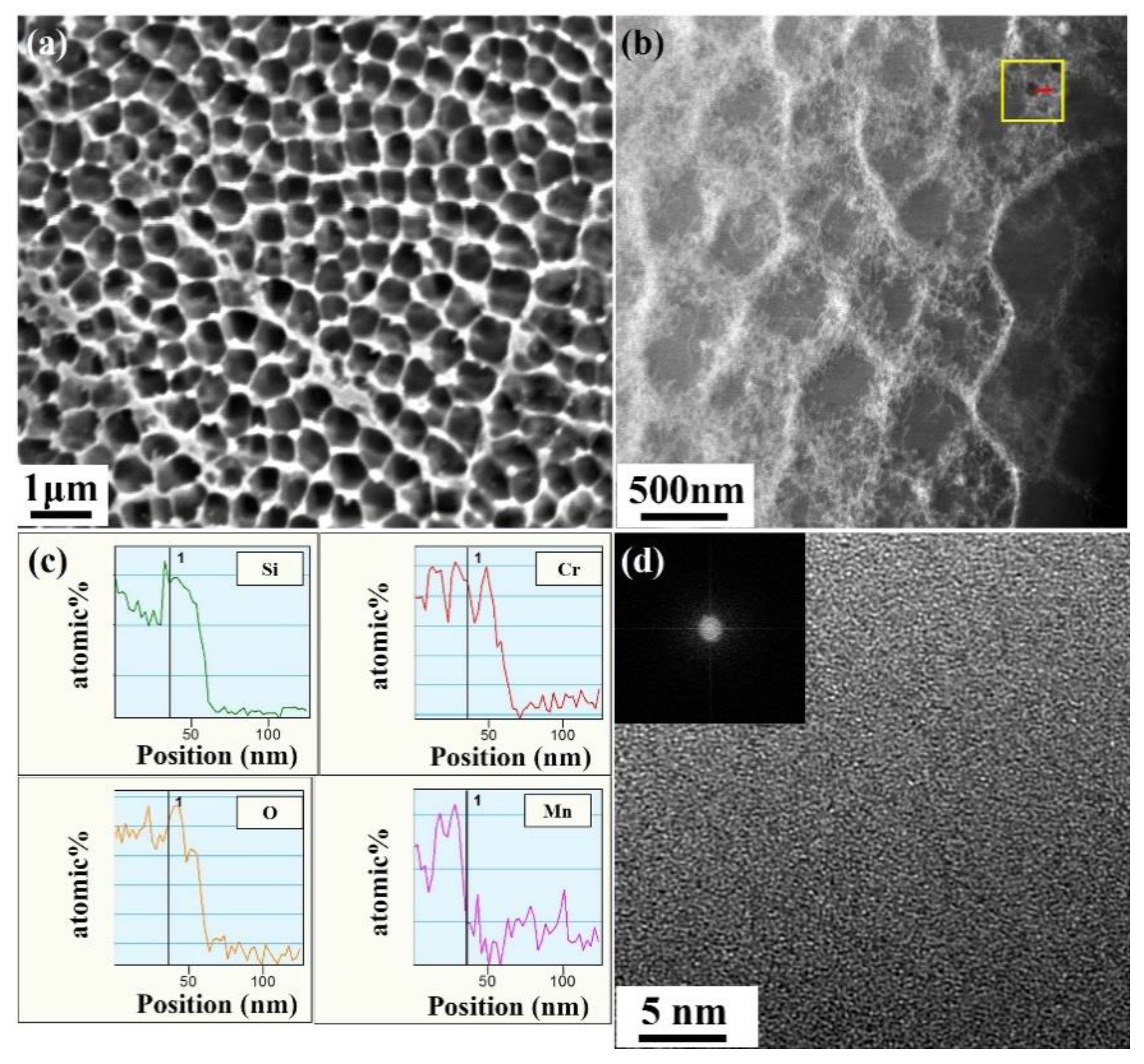
The typical microstructure of pre-irradiated 316L SS samples fabricated by SLM was investigated by SEM and TEM. Figure 2a shows SEM images of the polished and etched surfaces of the sample in which a fine cellular sub-grains structure is revealed. The average size of cell structures from the region in Figure 2a was approximately 400 nm. The formation mechanism of sub-grains structure of SLM specimens is due to the cellular growth mode under the high temperature gradient and high growth rate condition, which have also been found in welded 316L SS [27,28]. However, compared with that in welded 316L SS, the size of cellular structure in the SLM 316L SS samples is much smaller, due to the higher rapid solidification rate of approximately 107 K/s during the fabrication process [29]. In addition, a surface tension driven instability termed as the Benard–Marangoni surface instability (BMI instability) is also crucial to the formation of cellular patterns [28]. To study this sub-grain microstructure further, Figure 2b shows TEM images of samples prepared by a standard double-jet procedure. It is clear that sub-grains were surrounded with high density and enlarged dislocations networks, which can pin the dislocation during the deformation and thus increase the yield strength and hardness [10,30].
The TEM/energy dispersive X-ray spectroscopy (EDS) linear scanning was used to analyze the concentration of elements in the sub-grain boundaries (SGBs). It is worth noting that there is no discernible segregation of Cr or Mo for the region of SGBs, which is different from the results of Saeidi [31]. Qiu et al. [32] did not observe the presence of such elemental segregation either and reported that the chemical heterogeneity due to the dislocations acts as sinks for solute diffusion, which is influenced by Σ3 boundaries, the elastic strain energy, the grain boundary energy, and several factors, such as the observed locations. In addition, some nano-inclusions are also found in the STEM image. The results of EDS line scanning show that the nano-inclusions contain Si, Cr, O, and Mn. We analyzed multiple nano-inclusions in the specimens; the elemental species observed remained consistent. Figure 2d shows a high-resolution TEM (HRTEM) image taken at the boundary region of a nano-inclusion, in the inset, a selected area electron diffraction (SAED) pattern taken from the middle of the nano-inclusion. These images confirm that the nano-inclusions are amorphous. The high temperature applied during the fabrication process and residual oxygen gas in the chamber may play a key role in the formation of nano-inclusions.

3.2. Microstructure of Post-Irradiated Samples

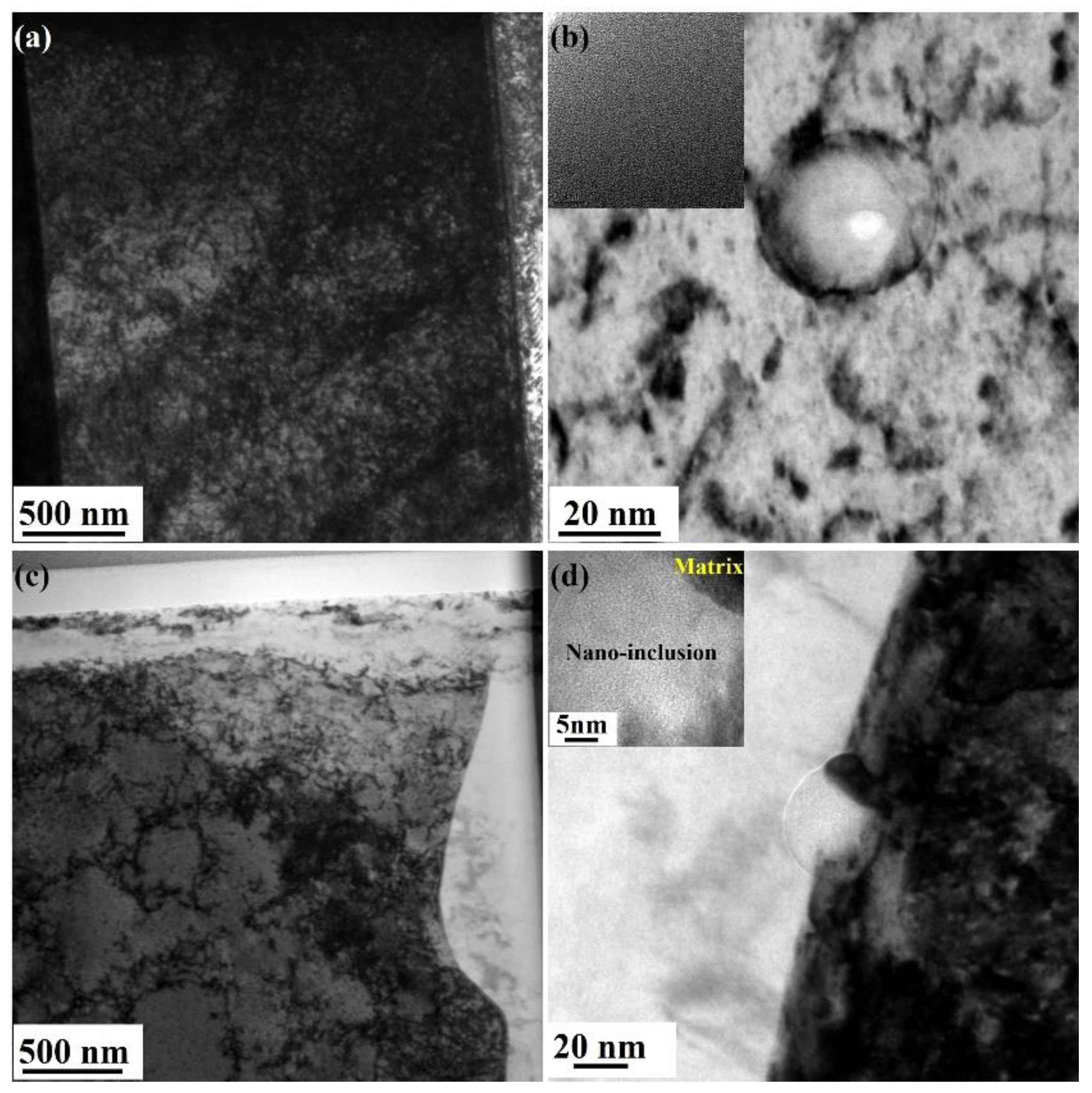
Bright-field images of the SLM 316 SS samples after Fe ions irradiation at RT and 450 °C with a dose of 1 dpa are shown in Figure 3a–d. Here, the cross sectional TEM specimens were thinned by FIB. Figure 3a–b shows that the size and morphology of cellular sub-grains and nano-inclusions of post-irradiated samples remain relatively constant compared with those of pre-irradiated samples. The same findings were observed in SLM 316L SS irradiated by He ions at 450 °C [20]. According to previous studies, the ion irradiation could induce annealing in materials, and, subsequently, recrystallization [33,34]. Considering that defects are trapped by sinks, the ion irradiation-based enhancements in diffusivity in the steady state can be defined as [21]:
D = 2 K k i v 2 + D v ,
where D’ is the total diffusion coefficient, Dv is the thermal diffusion coefficient, K is the damage rate, and k i v 2 is the sink strength for vacancies and interstitials. The sink strength of cellular sub-grains can be presented as [35]:
k i v 2 = 24 / d 2 ,
where d is the average size of the sub-grains. The Dv can be calculated according to the following Arrhenius equation [36]:
D v = D O exp [ Q ( R T ) ]
where the activation energy Q = 308 kJ/mol and the pre-exponential factor Do = 5.3 × 10⁻⁴ m2/s. Thus, Dv is calculated to be 2.96 × 10⁻²⁶ m2/s at 450 °C and D’ is calculated to be 3.14 × 10⁻¹⁸ m2/s, which is significantly larger than the thermal diffusion. According to Equation (2), D’ is equivalent to the thermal diffusion at a temperature of approximately 850 °C. Although this temperature is above the typical recovery temperature 0.4 Tm (around 450 °C) of 316L SS, the cellular sub-grains remain stable and do not recrystallize after irradiation. Saeidi et al. [27] also observed cellular structures in SLM 316L SS with heat treatment at 800 °C. Furthermore, the surrounding dislocations at SGBs differ under diverse irradiation temperature. Figure 3a shows that the density of dislocations increased under Fe ions irradiation at RT, and that dislocations extended toward the interior of sub-grains. However, the density of dislocations in Figure 3c decreased at 450 °C, and no dislocation extension was observed. Since the diffusivity of the vacancies caused by Fe ion irradiation are enhanced at improved temperature [37], most interstitials were recombined by the movable vacancies, and thus the extending rate of the dislocation slows down.
Figure 4 shows the distribution of dislocation loops in the post-irradiated samples; no other types of radiation defects could be observed. The loops are concentrated at the depth of 700–900 nm, consistent with the SRIM results. Figure 4a,c was used to calculate the size distribution of the dislocation loops; the corresponding results are illustrated in Figure 4b,d. The size of loops found in the samples irradiated at RT with a dose of 1 dpa was mainly distributed at around 5–7 nm, and the maximum size of dislocation loops of these samples reached 13 nm. In samples irradiated at 450 °C, the average loop size increased and peaked at 16 nm. The number density of dislocation loops in SLM 316L SS samples irradiated at RT/1 dpa and 450 °C/1 dpa were estimated to be approximately 2.7 × 10²²/m3 and 1.3 × 10²²/m3, respectively. Table 1 compares the average size and density of loops between SLM 316L SS samples and traditional SS samples. The mean loop size increased with increasing irradiation temperature in present work. The size and density of loops found in this work are similar to those of CW 316 SS irradiated by Xe ions at RT with a low dose of 0.67 dpa [38]. However, the average loop size in the SLM 316L SS sample was smaller than that in a SA 304 SS sample irradiated at a higher temperature [39]. In previous research, researchers also observed that SGBs and nano-inclusions could serve as sinks for He bubbles [20]. Thus, the increasing fraction of interfaces in the SLM sample compared with that in traditional samples may be crucial in the decreased mobility of radiation defects, which reduce loop size.

3.3. GIXRD Analysis of Pre- and Post-Irradiated Samples

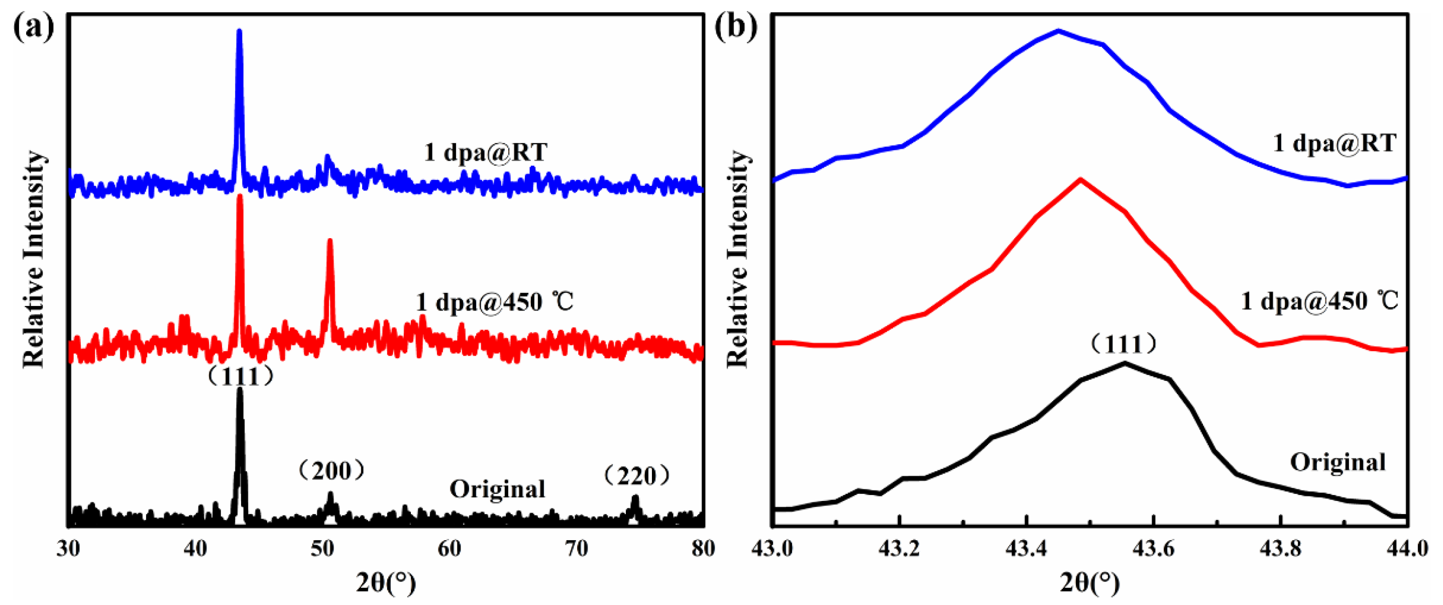
Figure 5 shows the GIXRD patterns of the SLM 316L SS samples obtained from different irradiation experiments. Comparison of the three patterns reveals that the post-irradiated specimens are primarily composed of the Face-Centered Cubic (FCC) lattice structure without a detectable second phase. After irradiation, the (111) peak showed a left shift and moved toward a lower angle. Figure 5b shows the enlarged (111) peak patterns and confirms that the 2θ increases with the decreasing irradiation temperature. According to the Bragg formula, the decrease of the diffraction angle means the increase of interplanar spacing which is proportional to the lattice constant. As the displacement damage of materials increase, the radiation-induced dislocation loops grow and the lattice distortion becomes larger. The results shown in Figure 5 indicate that the lattice swelling occurred after irradiation. However, the lattice swelling under high temperature irradiation is less than that under room temperature irradiation.

3.4. Hardness Property Analysis

Since the thickness of irradiated region is less than 1 μm, regular mechanical tests like the tensile test are unsuitable in this case. To reflect the effects of radiation-induced defects on the mechanical properties, the nanoindentation test is widely used. Figure 6a shows the average hardness versus depth of the SLM 316L SS samples subjected to Fe ions irradiation at different temperatures. Here, data of depths greater than 100 nm were selected due to the uncertainties associated with the shape of Berkovich diamond indenter. The results clearly demonstrate that the hardness of post-irradiated samples decreased with increasing depth. We compared the hardness increments of samples irradiation at RT with those irradiated at 450 °C, and the model developed by Nix-Gao was used to confirm the hardness of the post-irradiated samples [40]. Figure 6b shows that the bi-linearity region with a shoulder is around 220–250 nm, which is approximately 1/5 of the irradiation damage depth, for the samples irradiated at RT and 450 °C; this result reflects the hardness in the region extending down five times of the indenter depth [41]. The average hardness of the irradiated samples was calculated as 4.0 GPa and 3.7 GPa. Compared with the hardness of the un-irradiated samples, which was calculated as 2.8 GPa, the hardness of the post-irradiated samples increased with decreasing irradiation temperature. The hardness enhancement was 42.8% and 32.1% to the original specimens, respectively.
Irradiation hardening has been reported in many studies, and is known to be related to radiation defects, such as dislocation loops, acting as obstacles to the movement of dislocations [16,38]. The Orowan equation could be used to estimate the contribution of dislocation loops to irradiation hardening [40]. For a given material, the change in yield stress is proportional to the square root of the number density and size of dislocation loops. The yield stress is also proportional to the hardness of materials. Hence, the dislocation loops could have an important impact on irradiation hardening. Table 1 shows that the change in the loop size of the material irradiated at 450 °C is approximately 1.4 times higher than that of the specimens irradiated at RT. However, the change in the loop density of specimens irradiated at RT is approximately two times higher than that of specimens irradiated at 450 °C. Therefore, hardening of SLM 316L at a high temperature SS shows a significant recovery compared with that of samples irradiated at RT. In this work, the SLM 316L SS samples were irradiated with a higher dose of 1 dpa but achieved lower hardness enhancement compared with that of CW 316 SS irradiated at RT with a dose of 0.62 dpa (as shown in Table 2). The number density and size of dislocation loops play key role in hardness enhancement.

3.5. Corrosion Resistance in 0.9 wt.% NaCl Solution

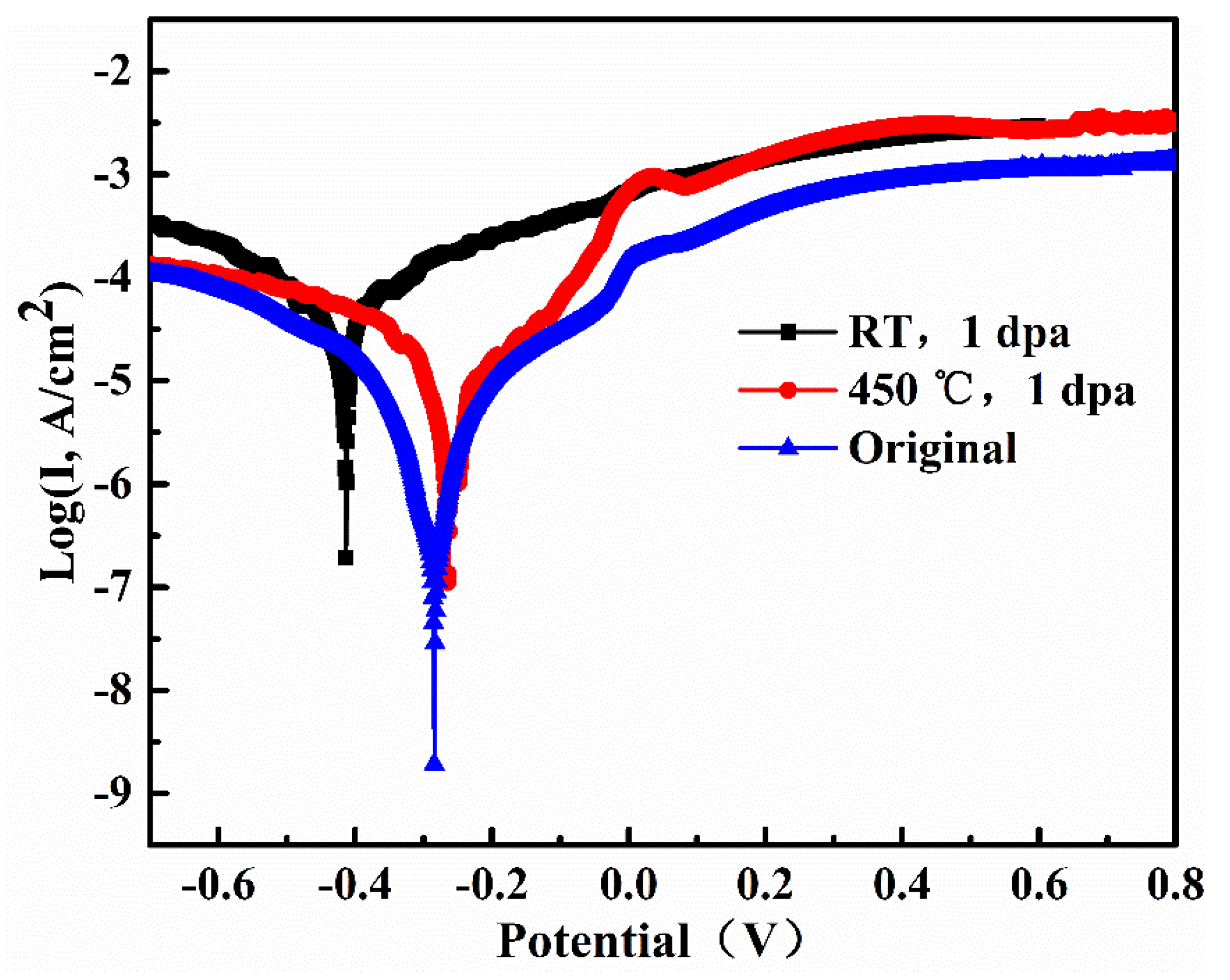
Figure 7 shows the polarization scans of pre- and post-irradiated SLM 316L SS samples collected in 0.9 wt.% NaCl, and Table 3 lists the corresponding parameters. In the original specimens, the current density (Jcor) was 0.80 μA/cm2, which is lower than that of traditional 316L SS samples tested in 9 g/L NaCl solution with a scan voltages ranging from −1 to 1 V [42]. Qi Chao et al. [29] also observed the same result when comparing SLM and traditional 316L SS. These findings are related to the different grain sizes and chemical compositions of the two specimens, which are fabricated by different process. High solidification rates prevent the formation of MnS and Cr-depletion zones in the SLM fabrication process, which increase the corrosion resistance of this sample. Table 3 shows that the current densities of post-irradiated specimens are higher than those of the original samples. Thus, the corrosion rate of SLM 316L SS samples increased after Fe ions irradiation, which shows a degradation of corrosion resistance. Moreover, a significant divergence in the current density was observed between the two irradiation temperatures (56.7 μA/cm2 for the samples irradiated at RT versus 8.726 μA/cm2 for the samples irradiated at 450 °C). As described above, much more dislocations were observed in the interior of sub-grains in the case of RT than the case of 450 °C. These dislocations tangled and connected with the sub-grain boundaries. In the corrosive environment, this structure accelerates the diffusion of metal atoms, and thus increases the current density. Another recent study investigating the radiation effect of corrosion resistance of 316 SS in 3% NaCl also revealed a degradation of corrosion resistance during Fe ions irradiation [43]. Cr depletion caused by irradiation may also affect the corrosion resistance of this material. Details of the mechanism for the degradation of corrosion resistance must be determined in future work.

4. Conclusions

In the present study, the evolution of the microstructure, hardness, and corrosion resistance of SLM 316L SS samples before and after Fe ions irradiation at different temperatures (RT and 450 °C) with a dose of 1 dpa was investigated by TEM, GIXRD, nanoindentation, and potentiodynamic polarization tests. The cellular sub-grains and nano-inclusions maintain stability after irradiation. The average dislocation loop size increased from 6 nm to 8.5 nm, and the number density decreased from 2.7 × 10²²/m3 to 1.3 × 10²²/m3 with the increasing temperature from RT to 450 °C. Compared with the traditional formed 316L SS samples, the increasing fraction of interfaces in the SLM sample reduced the mobility of radiation defects and thus improved the radiation resistance of 316L SS. Meanwhile, the evolution in microstructure of the SLM 316L SS specimens under Fe ions irradiation at different temperatures caused a significant diver in the hardness enhancement and corrosion current density. Considering the changes of SLM 316L stainless steel under irradiation conditions, it can be found that both the hardening and corrosion resistance performance are improved compared with traditional materials. By adjusting the preparation process to control the characteristics of sub-grain boundaries, the additive manufacturing technique will provide a promising method to promote the irradiation tolerance in extreme radiation environments.

Author Contributions

D.H.: study design and writing; Y.L.: microstructure analysis through TEM; X.C.: sample preparation through SLM; H.L.: nano-indentation and electric-chemistry corrosion data collection and analysis. All authors have read and agreed to the published version of the manuscript.

Funding

This research received no external funding.

Acknowledgments

The authors acknowledge the assistance of Tongmin Zhang, Long Kang, and Jinyu Li during the Fe ions irradiation experiments performed on the 320 kV platform at the Institute of Modern Physics, CAS. We gratefully thanks to the Suzhou Institute of Nano-Tech and Nano-Bionics, CAS for the support of nanoindentation tests.

Conflicts of Interest

The authors declare no conflict of interest.

References

  1. Zinkle, S.J.; Was, G.S. Materials challenges in nuclear energy. Acta Mater. 2013, 61, 735–758. [Google Scholar] [CrossRef]
  2. Şahin, S.; Übeyli, M. A review on the potential use of austenitic stainless steels in nuclear fusion reactors. J. Fusion Energy 2008, 27, 271–277. [Google Scholar] [CrossRef]
  3. Yang, S.; Yang, Z.; Wang, H.; Watanabe, S.; Shibayama, T. Effect of laser and/or electron beam irradiation on void swelling in SUS316L austenitic stainless steel. J. Nucl. Mater. 2017, 488, 215–221. [Google Scholar] [CrossRef] [Green Version]
  4. Gandy, D.W. Strategy/approach for qualification of nuclear components produced via additive manufacturing. In US DOE Advanced Methods of Manufacturing Workshop; US Department of Energy: Germantown, MD, USA, 2016. [Google Scholar]
  5. Kruth, J.P.; Mercelis, P.; van Vaerenbergh, J.; Froyen, L.; Rombouts, M. Binding mechanisms in selective laser sintering and selective laser melting. Rapid Prototyp. J. 2005, 11, 26–36. [Google Scholar] [CrossRef] [Green Version]
  6. Kranz, J.; Herzog, D.; Emmelmann, C. Design guidelines for laser additive manufacturing of lightweight structures in TiAl6V4. J. Laser Appl. 2015, 27, S14001. [Google Scholar]
  7. Zhong, Y.; Rännar, L.E.; Wikman, S.; Koptyug, A.; Liu, L.; Cui, D.; Shen, Z. Additive manufacturing of ITER first wall panel parts by two approaches: Selective laser melting and electron beam melting. Fusion Eng. Des. 2017, 116, 24–33. [Google Scholar] [CrossRef]
  8. Yusuf, S.M.; Nie, M.; Chen, Y.; Yang, S.; Gao, N. Microstructure and corrosion performance of 316L stainless steel fabricated by Selective Laser Melting and processed through high-pressure torsion. J. Alloys Compd. 2018, 763, 360–375. [Google Scholar] [CrossRef]
  9. Zhong, Y.; Liu, L.; Wikman, S.; Cui, D.; Shen, Z. Intragranular cellular segregation network structure strengthening 316L stainless steel prepared by selective laser melting. J. Nucl. Mater. 2016, 470, 170–178. [Google Scholar] [CrossRef]
  10. Liu, L.; Ding, Q.; Zhong, Y.; Zou, J.; Wu, J.; Chiu, Y.L.; Li, J.; Zhang, Z.; Yu, Q.; Shen, Z. Dislocation network in additive manufactured steel breaks strength–ductility trade-off. Mater. Today 2018, 21, 354–361. [Google Scholar] [CrossRef] [Green Version]
  11. Lou, X.; Andresen, P.L.; Rebak, R.B. Oxide inclusions in laser additive manufactured stainless steel and their effects on impact toughness and stress corrosion cracking behavior. J. Nucl. Mater. 2018, 499, 182–190. [Google Scholar] [CrossRef]
  12. Herzog, D.; Seyda, V.; Wycisk, E.; Emmelmann, C. Additive manufacturing of metals. Acta Mater. 2016, 117, 371–392. [Google Scholar] [CrossRef]
  13. Suryawanshi, J.; Prashanth, K.; Ramamurty, U. Mechanical behavior of selective laser melted 316L stainless steel. Mater. Sci. Eng. A 2017, 696, 113–121. [Google Scholar] [CrossRef]
  14. Chen, N.; Niu, L.L.; Zhang, Y.; Shu, X.; Zhou, H.B.; Jin, S.; Ran, G.; Lu, G.H.; Gao, F. Energetics of vacancy segregation to [100] symmetric tilt grain boundaries in bcc tungsten. Sci. Rep. 2016, 6, 1–12. [Google Scholar] [CrossRef] [PubMed]
  15. Jin, K.; Lu, C.; Wang, L.M.; Qu, J.; Weber, W.J.; Zhang, Y.; Bei, H. Effects of compositional complexity on the ion-irradiation induced swelling and hardening in Ni-containing equiatomic alloys. Scr. Mater. 2016, 119, 65–70. [Google Scholar] [CrossRef] [Green Version]
  16. Yabuuchi, K.; Kuribayashi, Y.; Nogami, S.; Kasada, R.; Hasegawa, A. Evaluation of irradiation hardening of proton irradiated stainless steels by nanoindentation. J. Nucl. Mater. 2014, 446, 142–147. [Google Scholar] [CrossRef]
  17. Sakaguchi, N.; Endo, M.; Watanabe, S.; Kinoshita, H.; Yamashita, S.; Kokawa, H. Radiation-induced segregation and corrosion behavior on Σ3 coincidence site lattice and random grain boundaries in proton-irradiated type-316L austenitic stainless steel. J. Nucl. Mater. 2013, 434, 65–71. [Google Scholar] [CrossRef]
  18. Jin, H.H.; Ko, E.; Lim, S.; Kwon, J.; Shin, C. Effect of irradiation temperature on microstructural changes in self-ion irradiated austenitic stainless steel. J. Nucl. Mater. 2017, 493, 239–245. [Google Scholar] [CrossRef]
  19. Jiao, Z.; Was, G.S. Precipitate behavior in self-ion irradiated stainless steels at high doses. J. Nucl. Mater. 2014, 449, 200–206. [Google Scholar] [CrossRef]
  20. Sun, X.; Chen, F.; Huang, H.; Lin, J.; Tang, X. Effects of interfaces on the helium bubble formation and radiation hardening of an austenitic stainless steel achieved by additive manufacturing. Appl. Surf. Sci. 2019, 467–468, 1134–1139. [Google Scholar] [CrossRef]
  21. Song, M.; Wang, M.; Lou, X.; Rebak, R.B.; Was, G.S. Radiation damage and irradiation-assisted stress corrosion cracking of additively manufactured 316L stainless steels. J. Nucl. Mater. 2019, 513, 33–44. [Google Scholar] [CrossRef]
  22. Stoller, R.E.; Toloczko, M.B.; Was, G.S.; Certain, A.G.; Dwaraknath, S.; Garner, F.A. On the use of SRIM for computing radiation damage exposure. Nucl. Instrum. Methods Phys. Res. Sect. B Beam Interact. Mater. Atoms 2013, 310, 75–80. [Google Scholar] [CrossRef]
  23. Kuleshova, E.A.; Fedotova, S.V.; Gurovich, B.A.; Frolov, A.S.; Maltsev, D.A.; Stepanov, N.V.; Margolin, B.Z.; Minkin, A.J.; Sorokin, A.A. Microstructure degradation of austenitic stainless steels after 45 years of operation as VVER-440 reactor internals. J. Nucl. Mater. 2020, 533, 152124. [Google Scholar] [CrossRef]
  24. Korepanova, N.; Gu, L.; Zhang, L.; Dai, Y. Evaluation of displacement cross-section for neutron-irradiated 15-15Ti steel and its swelling behavior in CiADS radiation environment. Ann. Nucl. Energy 2019, 133, 937–949. [Google Scholar] [CrossRef]
  25. Li, X.; Bhushan, B. A review of nanoindentation continuous stiffness measurement technique and its applications. Mater. Charact. 2002, 48, 11–36. [Google Scholar] [CrossRef]
  26. Chen, F.; Tang, X.; Huang, H.; Liu, J.; Li, H.; Qiu, Y.; Chen, D. Surface damage and mechanical properties degradation of Cr/W multilayer films irradiated by Xe20+. Appl. Surf. Sci. 2015, 357, 1225–1230. [Google Scholar] [CrossRef]
  27. Saeidi, K.; Gao, X.; Zhong, Y.; Shen, Z.J. Hardened austenite steel with columnar sub-grain structure formed by laser melting. Mater. Sci. Eng. A 2015, 625, 221–229. [Google Scholar] [CrossRef]
  28. Prashanth, K.G.; Eckert, J. Formation of metastable cellular microstructures in selective laser melted alloys. J. Alloys Compd. 2017, 707, 27–34. [Google Scholar] [CrossRef]
  29. Chao, Q.; Cruz, V.; Thomas, S.; Birbilis, N.; Collins, P.; Taylor, A.; Hodgson, P.D.; Fabijanic, D. On the enhanced corrosion resistance of a selective laser melted austenitic stainless steel. Scr. Mater. 2017, 141, 94–98. [Google Scholar] [CrossRef]
  30. Wang, Y.M.; Voisin, T.; McKeown, J.T.; Ye, J.; Calta, N.P.; Li, Z.; Zeng, Z.; Zhang, Y.; Chen, W.; Roehling, T.T.; et al. Additively manufactured hierarchical stainless steels with high strength and ductility. Nat. Mater. 2018, 17, 63–70. [Google Scholar] [CrossRef] [Green Version]
  31. Saeidi, K.; Gao, X.; Lofaj, F.; Kvetková, L.; Shen, Z.J. Transformation of austenite to duplex austenite-ferrite assembly in annealed stainless steel 316L consolidated by laser melting. J. Alloys Compd. 2015, 633, 463–469. [Google Scholar] [CrossRef]
  32. Qiu, C.; Al Kindi, M.; Aladawi, A.S.; Al Hatmi, I. A comprehensive study on microstructure and tensile behaviour of a selectively laser melted stainless steel. Sci. Rep. 2018, 8. [Google Scholar] [CrossRef] [PubMed]
  33. Gigax, J.G.; Kim, H.; Chen, T.; Garner, F.A.; Shao, L. Radiation instability of equal channel angular extruded T91 at ultra-high damage levels. Acta Mater. 2017, 132, 395–404. [Google Scholar] [CrossRef]
  34. Kaoumi, D.; Motta, A.T.; Birtcher, R.C. A thermal spike model of grain growth under irradiation. J. Appl. Phys. 2008, 104. [Google Scholar] [CrossRef] [Green Version]
  35. Was, G.S. Fundamentals of Radiation Materials Science: Metals and Alloys, 2nd ed.; Springer: New York, NY, USA, 2016. [Google Scholar]
  36. Rothman, S.J.; Nowicki, L.J.; Murch, G.E. Self-diffusion in austenitic Fe-Cr-Ni alloys. J. Phys. F Met. Phys. 1980, 10, 383–398. [Google Scholar] [CrossRef]
  37. Yang, T.; Xia, S.; Guo, W.; Hu, R.; Poplawsky, J.D.; Sha, G.; Fang, Y.; Yan, Z.; Wang, C.; Li, C.; et al. Effects of temperature on the irradiation responses of Al0.1CoCrFeNi high entropy alloy. Scr. Mater. 2018, 144, 31–35. [Google Scholar] [CrossRef]
  38. Huang, H.F.; Li, J.J.; Li, D.H.; Liu, R.D.; Lei, G.H.; Huang, Q.; Yan, L. TEM, XRD and nanoindentation characterization of Xenon ion irradiation damage in austenitic stainless steels. J. Nucl. Mater. 2014, 454, 168–172. [Google Scholar] [CrossRef]
  39. Chen, D.; Murakami, K.; Dohi, K.; Nishida, K.; Soneda, N.; Li, Z.; Liu, L.; Sekimura, N. Depth distribution of Frank loop defects formed in ion-irradiated stainless steel and its dependence on Si addition. Nucl. Instrum. Methods Phys. Res. Sect. B Beam Interact. Mater. Atoms 2015, 365, 503–508. [Google Scholar] [CrossRef]
  40. Nix, W.D.; Gao, H. Indentation size effects in crystalline materials: A law for strain gradient plasticity. J. Mech. Phys. Solids 1998, 46, 411–425. [Google Scholar] [CrossRef]
  41. Huang, H.F.; Li, D.H.; Li, J.J.; Liu, R.D.; Lei, G.H.; He, S.X.; Huang, Q.; Yan, L. Nanostructure variations and their effects on mechanical strength of Ni-17Mo-7Cr alloy under Xenon ion irradiation. Mater. Trans. 2014, 55, 1243–1247. [Google Scholar] [CrossRef] [Green Version]
  42. Muthukumaran, V.; Selladurai, V.; Nandhakumar, S.; Senthilkumar, M. Experimental investigation on corrosion and hardness of ion implanted AISI 316L stainless steel. Mater. Des. 2010, 31, 2813–2817. [Google Scholar] [CrossRef]
  43. Hug, E.; Babu, R.P.; Monnet, I.; Etienne, A.; Moisy, F.; Pralong, V.; Enikeev, N.; Abramova, M.; Sauvage, X.; Radiguet, B. Impact of the nanostructuration on the corrosion resistance and hardness of irradiated 316 austenitic stainless steels. Appl. Surf. Sci. 2017, 392, 1026–1035. [Google Scholar] [CrossRef]
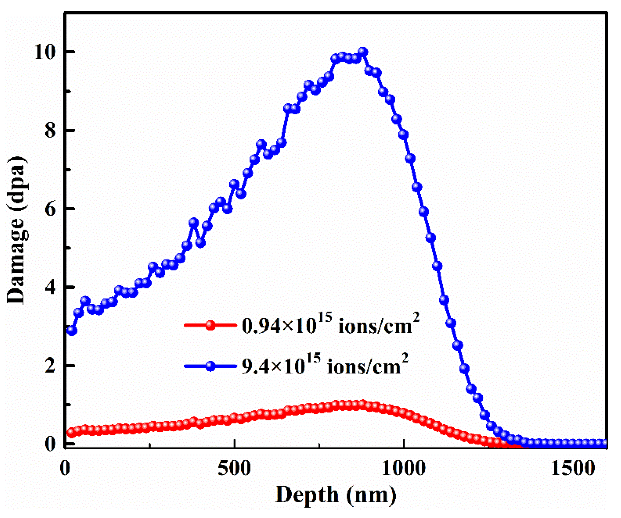
Figure 1. Depth profiles of damage events under a series of Fe ions irradiation conditions.
Metals 10 01140 g001
Figure 2. Microstructure of pre-irradiated SLM 316L SS. (a) SEM image reveals the cellular sub-grains. (b) STEM image shows the cellular sub-grains, nano-inclusions, and dislocations. The yellow square indicates the nano-inclusions. (c) Result of EDS line scanning shows the concentration of elements against distance corresponding to the red line shown in the graph (b). (d) HRTEM image of an area in the middle of nano-inclusions. The inset shows a complete amorphous structure in the middle of a nano-inclusion.
Metals 10 01140 g002
Figure 3. Microstructure of post-irradiated SLM 316L SS. (a) TEM image reveals the cellular sub-grains irradiated by Fe ions at RT with a dose of 1 dpa. (b) TEM image shows the nano-inclusions irradiated by Fe ions at RT with a dose of 1 dpa. The inset is obtained from the middle of nano-inclusion, and shows a complete amorphous structure. (c) TEM image reveals the cellular sub-grains irradiated by Fe ions at 450 °C with a dose of 1 dpa. (d) TEM image shows the nano-inclusions irradiated by Fe ions at 450 °C with a dose of 1 dpa. The inset is obtained from an area with the embedded nano-inclusion in the surrounding steel matrix, which shows a complete amorphous structure.
Metals 10 01140 g003
Figure 4. Distribution of dislocation loops in post-irradiated SLM 316L SS. (a) TEM image reveals the distribution of dislocation loops in specimens irradiated by Fe ions at RT with a dose of 1 dpa. (b) Size distribution of the dislocation loops. (c) TEM image reveals the distribution of dislocation loops in specimens irradiated by Fe ions at 450 °C with a dose of 1 dpa. (d) Size distribution of the dislocation loops.
Metals 10 01140 g004
Figure 5. (a) GIXRD patterns of SLM 316L SS samples before and after irradiation. (b) Enlarged (111) peak patterns of SLM 316L SS samples before and after irradiation.
Metals 10 01140 g005
Figure 6. (a) Depth profiles of hardness and (b) plots of H2−1/D for SLM 316L SS samples before and after Fe11+ irradiation at different temperatures.
Metals 10 01140 g006
Figure 7. Polarization curves of pre- and post-irradiated SLM 316L SS samples.
Metals 10 01140 g007
Table 1. Average size and number density of dislocation loops in Fe ions irradiated SLM 316L and traditional SS samples.
MaterialTemperature (°C)Dose (dpa)Size (nm)Density (× 1022/m3)References
SLM 316L SSRT162.7This work
45018.51.3
CW 316 SSRT0.6253.7[38]
SA 304 SS3501.259.63[39]
Table 2. Comparison of hardness enhancement between SLM 316L and CW 316 SS samples.
MaterialTemperature (°C)Dose (dpa)Hardness EnhancementReferences
SLM 316L SSRT150%This work
450142%
CW 316 SSRT0.6262%[38]
Table 3. Comparison of Jcor between the pre- and post-irradiated SLM 316L and traditional 316L SS samples.
MaterialTemperature (°C)Dose (dpa)Jcor (μA/cm2)Reference
Original SLM SS//0.80This work
AISI SS//1218.7[42]
Post-irradiated SLM SSRT156.7This work
45018.726This work