Article

Corrosion Behavior and Morphology of Passive Films Modified with Zinc–Aluminum Simultaneous Treatment on Different Metals

1
Hebei Key Lab of Power Plant Flue Gas Multi-Pollutants Control, Department of Environment Science and Engineering, North China Electric Power University, Baoding 071003, China
2
Environmental Systems Optimization, College of Environmental Science and Engineering, North China Electric Power University, Beijing 102206, China
*
Author to whom correspondence should be addressed.
Metals 2020, 10(8), 986; https://doi.org/10.3390/met10080986
Submission received: 23 June 2020 / Revised: 18 July 2020 / Accepted: 21 July 2020 / Published: 22 July 2020

Abstract

:
Passive films were formed on A508-3 steel (A508-3), 304L stainless steel (304L) and Incoloy 800 (In800) with blank/zinc/zinc–aluminum treatments in air at 300 °C. The electrochemical corrosion behaviors of different metals were investigated through potentiodynamic polarization, electrochemical impedance spectroscopy and the Mott–Schottky technique. The morphology and composition of passive films were analyzed using scanning electron microscopy (SEM) and energy dispersive spectrometry (EDS). The zinc–aluminum treatment effectively reduced the corrosion current and increased the impedance of A508-3 and 304L, but had a weak effect on In800. The zinc–aluminum treatment reduced the carrier concentration of A508-3 and changed the semiconductor property of 304L and In800. The order of zinc–aluminum treatment for improving the corrosion resistance of three metals was: A508-3 > 304L > In800. In addition, the zinc–aluminum treatment enhanced the density and smoothness of passive films. According to the composition analysis, spinel ZnAl2O4 was formed on three metals; however, the amount of spinel varied with the content of nickel and chromium in different metals, which affected the results of using this technology.

Graphical Abstract

1. Introduction

The main structural materials in the primary circuit of pressurized water reactor (PWR) nuclear power plants are composed of stainless steel, nickel alloy and low alloy ferritic steel [1,2,3,4,5]. In the primary water chemical control technology, boric acid is often used as a neutron absorber to absorb soluble neutrons, and lithium hydroxide is used as an alkaline regulator to reduce the corrosion of materials [6]. In recent years, to improve the safety and economy of reactor operation, zinc injection technology, which was previously widely used in boiling water reactors (BWR), has been applied to the primary circuit water of most PWRs to mitigate stress corrosion cracking, intergranular corrosion and excessive radiation doses [7,8]. Zinc was used to participate in the formation of the passive film on the surface of the material, to replace the original radionuclide (such as 58Co and 60Co) and to change the composition and structure of the passive film [9,10,11,12].
In actual operation, 64Zn in natural zinc will be activated and converted to 65Zn with strong radioactivity. The injection of expensive depleted zinc will increase the operating costs [13,14,15,16]. The half-life periods of the radioactive isotopes of aluminum are all quite short, which will have no effect on the radiation dose in the PWR primary loop [17], and using aluminum to replace a part of the zinc was expected to improve the safety of the primary circuit and minimize costs. In previous research [18], simultaneous zinc and aluminum injection was shown effectively improve the corrosion resistance of 316L stainless steel. Researchers proposed that aluminum could combine with zinc to participate in the formation of the passive film to make the morphology of the passive film denser, and to generate a ZnAl2O4 phase with extremely low solubility and high stability, which enhances the corrosion resistance of the passive film.
This technology was used to conduct pre-experiments on different metals in laboratory conditions. The preliminary electrochemical experiment results showed interesting phenomena: for relatively corrosive metals (such as carbon steel), this technology greatly improved the corrosion resistance, even more so than the effect of zinc injection technology. For nickel alloys and other metals with excellent corrosion resistance, this technology did not show the effect of improving corrosion resistance. However, it was not possible to rely on simple polarization curves and visual observations to determine whether the simultaneous injection of zinc and aluminum could generate key substances (ZnAl2O4) in passive films on different metals. If this technology could indeed generate ZnAl2O4 on the surface of highly corrosion-resistant metals and form a dense passive film, it would have a certain protective effect for the equipment in long-term service, and also have a guiding significance for subsequent research and applications. In addition, due to the different element distributions, the structure and composition of the passive films formed on different metals in a corrosive environment are also different, which indicates that the elemental composition of the material will prevent zinc and aluminum from effectively participating in the film formation reaction. However, the specific influence of material composition on the corrosion resistance has not yet been studied.
In this paper, the passive films were modified on different materials (A508-3 steel, 304L stainless steel and Incoloy 800 alloy) with a zinc treatment and a zinc–aluminum simultaneous treatment, both at 300 °C. Salt bath oxidation in air at a high temperature effectively accelerated the formation of the passive film and presented a clear morphology. The corrosion behaviors of passive films on different metals were comparatively studied using electrochemical polarization, electrochemical impedance spectroscopy (EIS) and the Mott–Schottky technique. In addition, the morphology and composition of passive films on different metal surfaces were comparatively analyzed using scanning electron microscopy (SEM) and energy dispersive spectrometry (EDS).

2. Materials and Methods

2.1. Samples Preparation

A508-3 steel (A508-3), 304L stainless steel (304L) and Incoloy 800 alloy (In800), which are often used as primary circuit structural materials, were selected as the experimental materials. The elemental compositions of these materials are shown in Table 1.
All materials were processed into a sample size of 10 mm × 10 mm × 2 mm, polished sequentially with wet silicon carbide metallographic sandpaper from 400 grit to 2000 grit, and burnished with Al2O3 polishing powder (granularity 0.3 μm). Then they were cleaned with ethanol absolute (analytical reagent) and deionized water in an ultrasonic environment. After drying with air, the samples were stored in a dryer until use.

2.2. Solutions Preparation

In order to simulate the actual corrosion of the material in the water containing B3+ and Li+ in the primary circuit of the PWRs, a solution containing boric acid and lithium hydroxide was prepared and used as a blank group (G(blank)) [6,19]. On this basis, 0.24 mol/L ZnSO4 and 0.12 mol/L ZnSO4 + 0.12 mol/L Al2(SO4)3 were additionally added as a zinc treatment group (G(Zn)) and a zinc–aluminum treatment group (G(Zn + Al)), respectively. The compositions of the solutions are shown in Table 2.

2.3. High Temperature Treatment

The samples were put in a crucible and then a few drops of different solutions were added onto the samples until the majority of the area was covered with salt solution. Then, the crucible was put in a muffle and kept at 300 °C for 90 min. The same salt solution was used to quench the salt bath every 30 min to accelerate the formation of the passive film, and finally the samples were cooled naturally.

2.4. Electrochemical Measurements

The electrochemical measurements included electrochemical polarization, EIS and the Mott–Schottky technique, all of which were conducted with a PARSTAT2273 potentiostat (Princeton, NJ, USA) in a three-electrode system. The reference electrode was a saturated calomel electrode, and the counter electrode was a platinum electrode with the dimension of 10 mm × 5 mm × 0.2 mm. The working electrode was made by tying the oxidized sample to the electrode holder using PTFE tape with an exposed area of 0.2826 cm2. The electrolyte solution was a 0.15 mol/L H₃BO₃ + 0.0375 mol/L Na2B4O7·10H2O buffered solution (pH = 8.4), which provided a stable weak alkali environment. Pure N2 was aerated into the system for 30 min to ensure test stability before all experiments. Each experiment was performed in triplicate.
The electrochemical potentiodynamic polarization curves were recorded on a potential range between −0.5 V and 1.0 V against the open circuit potential at a scan rate of 0.001 V/s. The corrosion current and corrosion potential were determined using the three-point method proposed by S. Barnartt [20,21]. The EIS spectra were recorded at open circuit potential with a frequency range between 106 Hz and 10−2 Hz and an amplitude of 0.005 V, and each frequency decade contained 12 points. The equivalent circuit diagram and fitting parameters were simulated by ZSimpwin software (V3.21, EChem Software). The Mott–Schottky curve test was conducted by gradually increasing the polarization potential from −1.0 V to 1.2 V with a potential step of 0.01 V and a frequency of 1 kHz to measure the capacitance.

2.5. Morphology and Composition Analysis

The oxidized samples of the three materials generated under different conditions were observed using SEM (S4800, Hitachi, Japan) for the morphology of the passive film with an accelerating voltage of 15.0 kV. EDS (EMAX-350, Horiba, Japan) was used to detect the elemental composition of the observed specific areas.

3. Results

3.1. Potentiodynamic Polarization

The potentiodynamic polarization curves of the passive films formed on A508-3, 304L and In800 with different treatment methods are shown in Figure 1a–c, respectively. Due to the anodic polarization curves of certain groups that did not exhibit the Tafel regions, the corrosion current (Icorr) and corrosion potential (Ecorr) were calculated using the weakly polarized three-point method proposed by Barnartt [21,22,23], and polarization data in the overpotential range of 10–70 mV were selected to calculated the corrosion current and corrosion potential. The corrosion current density (Icorr) and corrosion potential (Ecorr) data, which were the average values from three repeated experiments, are shown in Table 3.
Due to the different properties of the materials, clear differences could be seen in the corrosion currents under a blank condition. In800 had the best corrosion resistance, followed by 304L, and A508-3 had the worst. After zinc treatment, the corrosion current density of all three metals was reduced. After zinc–aluminum treatment, the corrosion current densities of A508-3 and 304L continued to decrease slightly, while the corrosion current density of In800 increased. This behavior suggested that the zinc treatment could effectively improve the corrosion performance of the three investigated alloys. The most significant effect was noticed in the case of A508-3. In contrast, the zinc–aluminum treatment further improved the corrosion resistance in the case of A508-3 and 304L alloys, while for In800, the zinc–aluminum treatment did not. The corrosion current of In800 treated with zinc–aluminum was slightly higher than that of the untreated sample.
In addition, compared to the untreated sample, the corrosion potential of A508-3 and 304L with the zinc treatment or zinc–aluminum treatment decreased. However, the corrosion potential of In800 did not change significantly under these treatment methods. According to the mixed potential theory, an increase in anodic current density or a decrease in cathodic current density can result in a decrease in corrosion potential. The decreases in corrosion potential of A508-3 and 304L with the zinc or zinc–aluminum treatment could be attributed to the reduction in the sum of all cathodic reaction rates, and the corrosion current also decreased. The corrosion potential changes of In800, resulting from different treatments, could also be attributed to the changes in the corrosion current densities.

3.2. EIS

The recorded EIS spectra of the passive films formed on A508-3, 304L and In800 with different treatment methods are shown in Figure 2. ZSimpwin software was used to fit the experimental EIS data.
It is generally assumed that passive films formed on materials (commonly used in the primary circuits of PWRs) under high temperatures have a double-layer structure [9,24,25]. The inner layer is a dense protective oxide film with high chromium content, which is formed by the solid growth of the substrate, and the outer layer is a loose protective film with high iron content, which is formed by metal dissolution and oxide precipitation [26,27]. Several equivalent circuits were selected to fit the EIS data. The most fitted equivalent circuit diagrams for A508-3, 304L and In800 were selected to calculate the electronic component parameters based on the mechanism of electrochemical process, and these are shown in Figure 3a,b, respectively [28,29]. In these circuit diagrams, Rs represents the solution and wire resistance in a three-electrode system. The film is composed of two parts in series, and each part is connected by a constant phase element (CPE, Qin/out) and a resistance (Rin/out) in parallel. Qout and Rout can be regarded together as the impedance of the outer layer of the passive film. Qin and Rin can be regarded together as the impedance of the inner layer of the passive film. Q, which can be expressed as Q = (jw)−n/Y, has two parameters: n is the dispersion index, which can evaluate the dispersion effect of the passive film. When n = 1, Y is equal to the capacitance, and when n = 0.5, Y represents the Warburg impedance. The effective capacitance ( C eff ) could be calculated according to the following Brug’s Equation (1) [29,30,31,32,33]. In addition, on this basis, an inductive component (L) appears in the circuit diagram of A508-3. The appearance of inductance is usually considered to result from the instability of the film leading to surface changes during the measurement due to surface adsorption–desorption and dissolution [34].The fitting parameters of each component are listed in Table 4.
C eff = Y 1 / n · R ( 1 n ) / n
It could be seen from the n value of Qout (close to 0.5) in the G(blank) and G(40Zn) of A508-3 that the outer layers of the passive films formed on A508-3 with the blank treatment and zinc treatment were close to the Warburg impedance caused by semi-infinite diffusion, which indicates that concentration polarization occured on the surface of passive films fomed on A508-3. The values of Rin for all specimens were much larger than those of Rout and Rs, which implied that the corrosion processes were primarily controlled by the charge transfer process at the outlayer/inner interface within the passive films, and the inner layer of the passive film formed on A508-3 was less protective than that of 304L and In800. Moreover, the Rin value of A508-3 was smaller than that of 304L, and that of 304L was smaller than that of In800. The phenomenon wherein all materials’ Qin values were larger than their Qout values might result from the fact that the inner layer was much thinner than the outer layer, and the effective area of the outer layer was also much smaller than that of inner layer.
Compared to the blank group, zinc treatment effectively increased the resistance of the passive films formed on all three materials, and the corrosion resistance of the films was clearly enhanced, which was consistent with the results in the potentiodynamic polarization curves. In addition, the zinc–aluminum treatment also significantly increased the resistance of passive films formed on A508-3 and 304L, compared to the blank group, but the increases were less than those derived from the zinc treatment. For In800, the zinc–aluminum treatment only slightly increased the resistance of the passive film. Considering the results in the polarization curves, it could not be effectively judged whether this treatment method would improve the corrosion resistance of In800.

3.3. Mott–Schottky Curve

When analyzing the capacitance of a semiconductive oxide film, usually the space charge layer’s capacitance alone is considered, and the relationship between the space charge layer’s capacitance and the potential can be studied through the Mott–Schottky theory in order to analyze the semiconductor properties of the passive film. The semiconductor type of the passive film can be judged by the positive (n-type) or negative (p-type) slope of a specific segment on the Mott–Schottky curve. At the same time, the carrier concentration ( N ) and flat band potential ( E f b ) of the passive film can be calculated by the Mott–Schottky equation as follows (which is essentially a linear regression equation) [35,36,37]:
1 C 2 = ± 2 ε ε 0 e N ( E E f b K T e )   ( + :   n - type ; :   p - type )
where E f b is the flat band potential; N is the carrier concentration and the surface area is 0.2826 cm2 when calculating; ε is the relative dielectric constant and its value is generally assumed to be 12 for a passive film formed on a metal surface [38,39]; ε 0 is the vacuum dielectric constant (8.85 × 10¹⁴ F/cm); e is the electron charge (1.602 × 10¹⁹ C); K is the Boltzmann constant (1.38 × 10²³ J/K); and T is the absolute temperature.
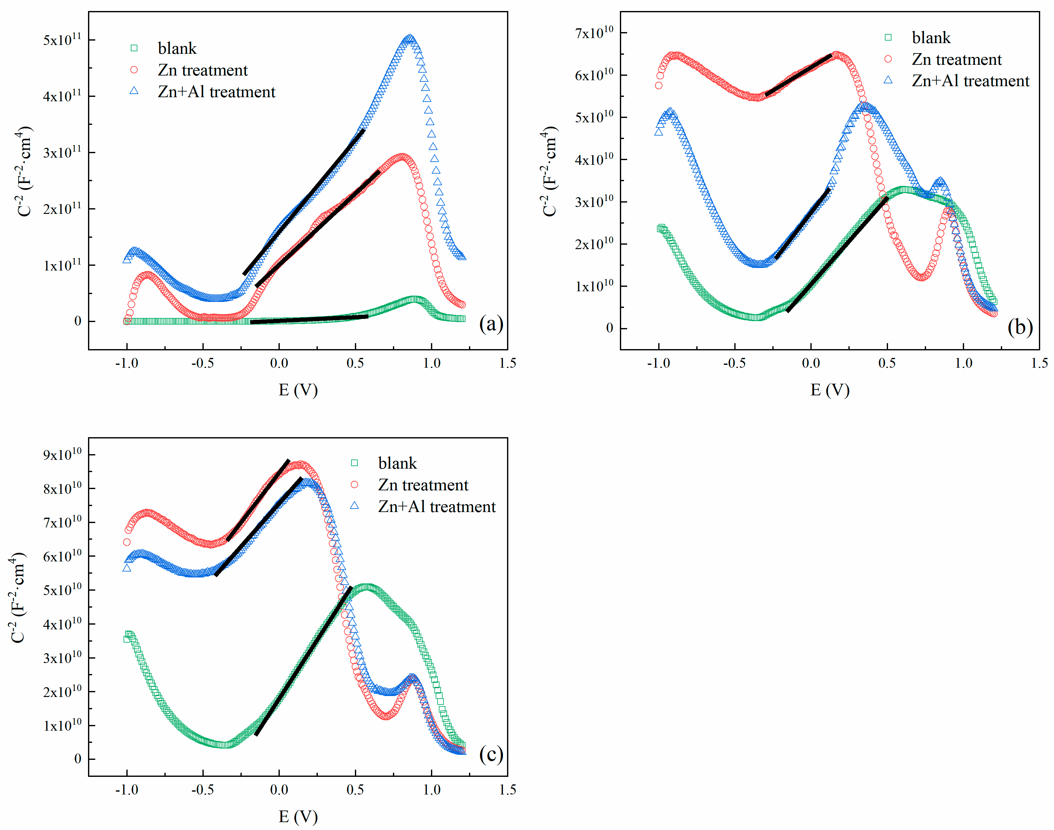
It can be seen from this equation that the greater the absolute value of the slope of the straight-line segment, the smaller the carrier concentration in the film, thus, the change in the corrosion behaviors of the metals can be inferred through the semiconductor type and the carrier concentration. The Mott–Schottky curves of the passive films formed on A508-3, 304L and In800 with different treatment methods are shown in Figure 4a–c, respectively. The corresponding n-type semiconductor parameters ( N and E f b ) of the passive films, which were the average values from parallel experiments, are listed in Table 5.
The passive films formed on A508-3 with three treatment methods all exhibited the same n-type semiconductor properties in the passivation potential range, but under the conditions of zinc treatment and zinc–aluminum treatment the carrier concentration was reduced by an order of magnitude. The effect of the zinc–aluminum treatment was more distinct than that of the zinc treatment. An inflection point at −0.04 V appeared in both treatment methods, making the linear slope of the voltage range above −0.04 V smaller. This was likely the result of the presence of the second donor energy level in the passive film, which corresponded to the ionization of the donor in the passive film.
In the blank group, 304L and In800 reflected the transition from n-type to p-type semiconductor in the passivation potential range, with the n-type semiconductor being dominant. Both the zinc treatment and zinc–aluminum treatment changed the semiconductor properties of these two materials to n-p-n type, with the p-type semiconductor dominant. This indicated that new substances were formed on the surfaces of the passive films after zinc treatment and zinc–aluminum treatment, and the crystal types of these new substances may be the same under these two treatment methods [40]. The zinc–aluminum treatment slightly reduced the carrier concentration of the passive film formed on 304L. Neither the zinc treatment nor the zinc–aluminum treatment reduced the carrier concentration of the passive films formed on In800. However, the flat band potential of 304L and In800 underwent a significant negative shift with the zinc–aluminum treatment. These phenomena indicated that the zinc–aluminum treatment affected the film formation of different materials in different ways.

3.4. Morphology and Composition Analysis

The passive films formed on A508-3, 304L and In800 reflected different morphologies and composition characteristics under different treatment methods, which directly resulted in the different effects of the zinc–aluminum treatment in improving the corrosion resistances of the different metals. S4800 and EMAX-350 were used to perform SEM and EDS with an accelerating voltage of 15.0 kV, and EDS point scanning was performed on specific areas, which are marked in figures with dotted lines. The composition analysis results (atomic percent, At%, and Error, %) were normalized and are listed on the side of the corresponding scan position.

3.4.1. A508-3

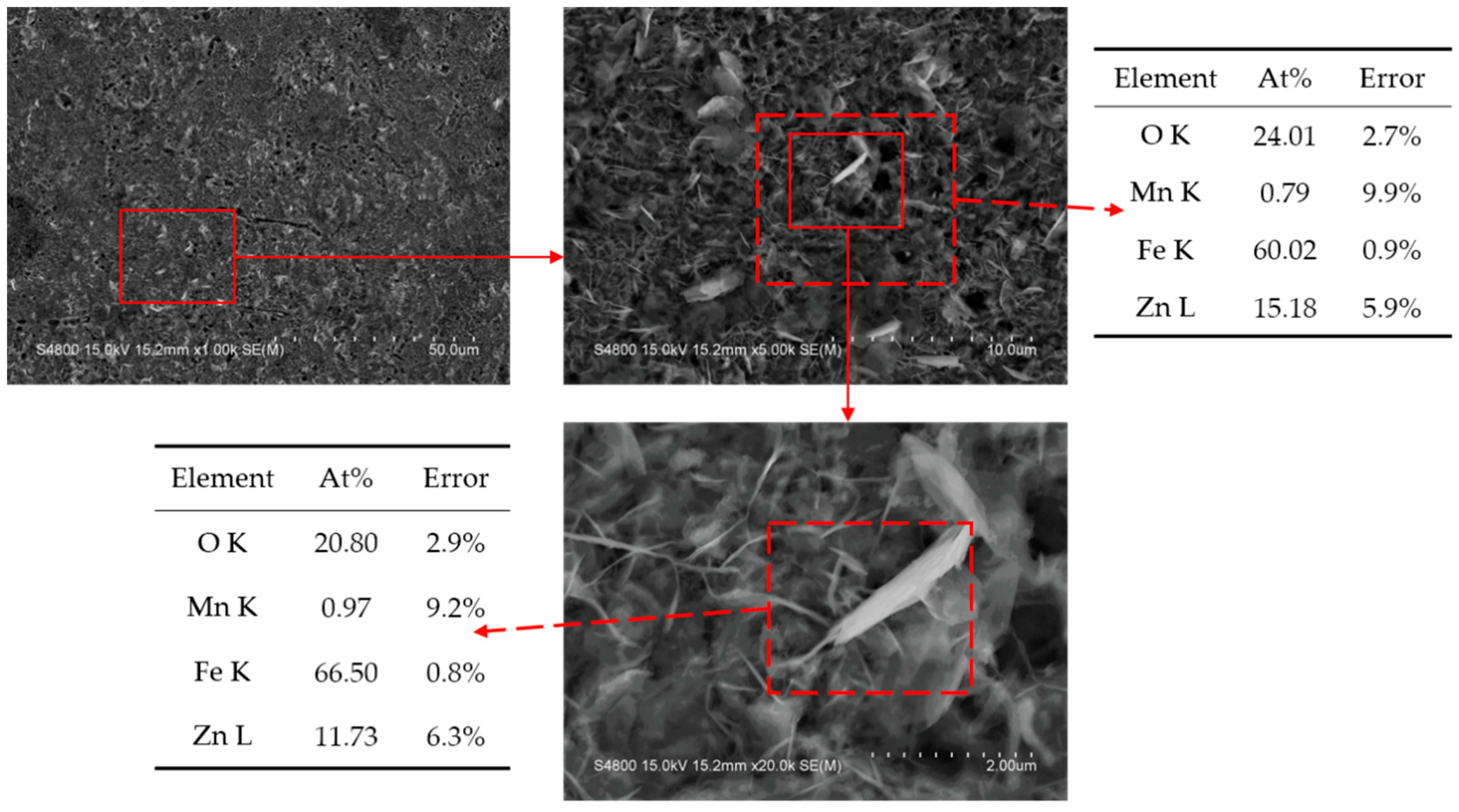
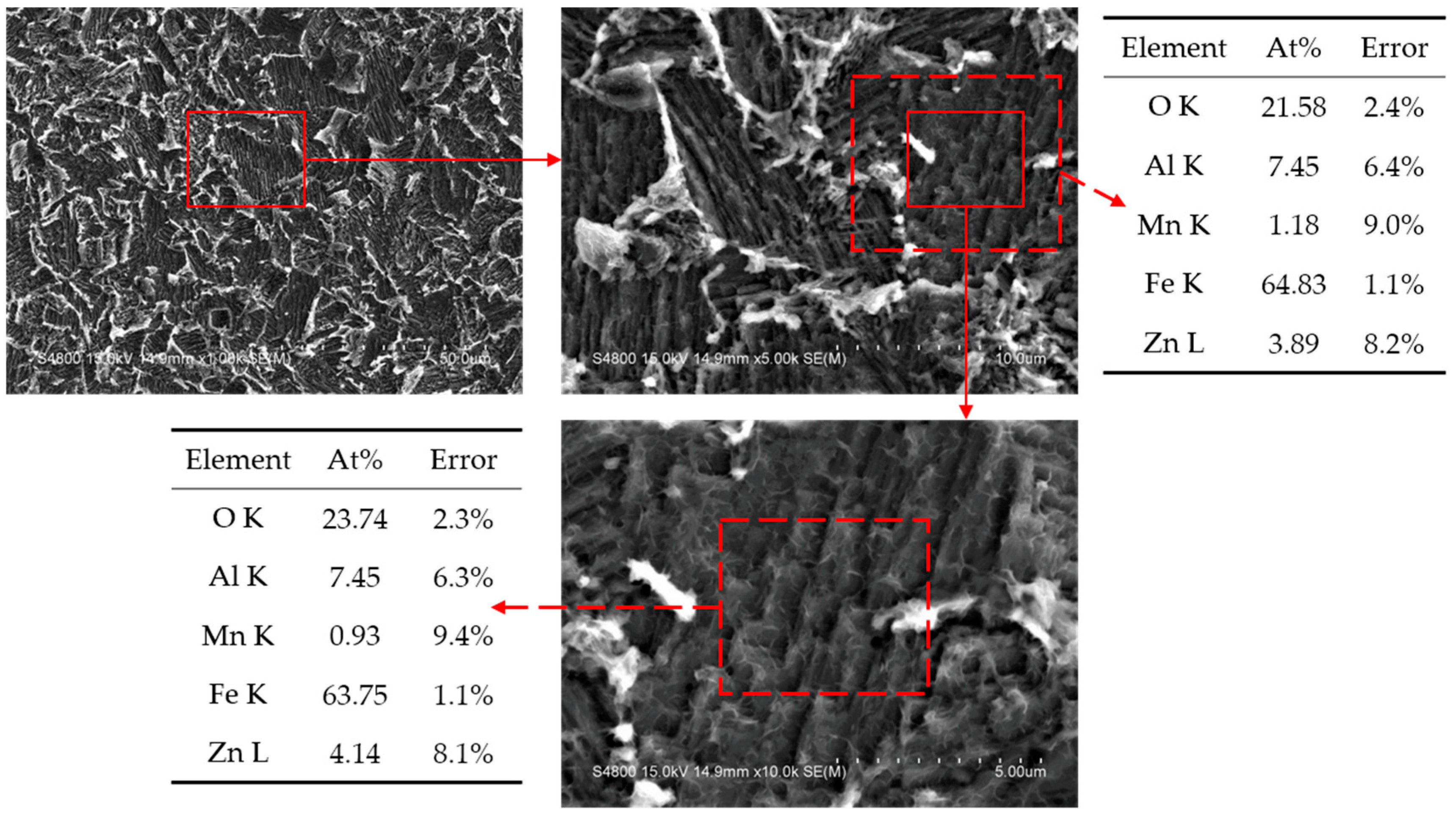
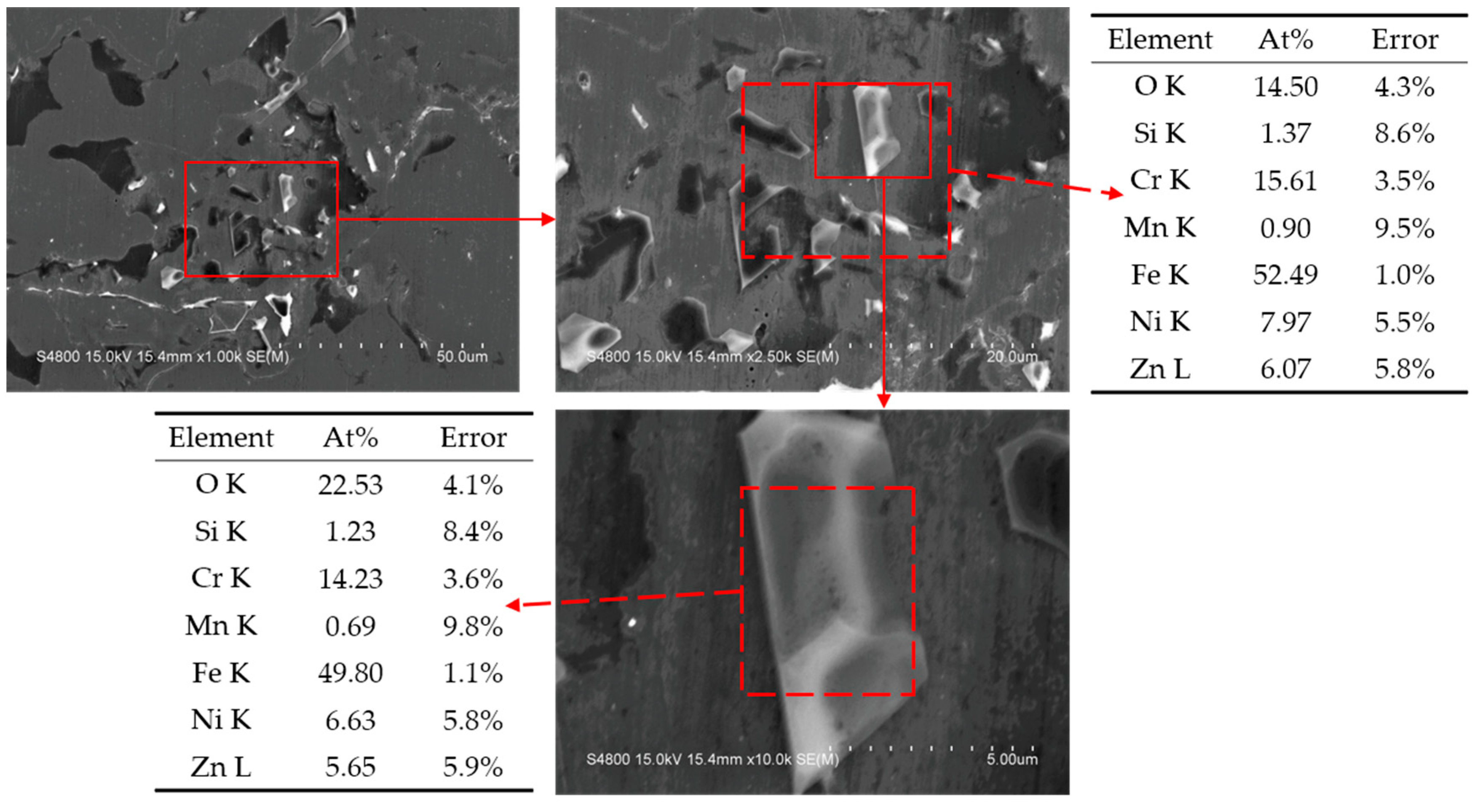
The SEM images and corresponding composition analyses of the passive films formed on A508-3 with blank treatment, zinc treatment and zinc–aluminum treatment are shown in Figure 5, Figure 6 and Figure 7, respectively.
The loose surface morphology could be observed on the passive film formed on A508-3 with the blank treatment (as shown in Figure 5), and the appearance of pitting corrosion pits could be easily observed, accompanied by the accumulation of a large number of corrosion products, indicating that the content of the oxygen element was high in the places where pitting occured. Furthermore, it could be seen form the composition that most of the products were iron oxides. After using the zinc treatment or the zinc–aluminum treatment, the surfaces of the passive films showed different morphologies, but all became denser, and many regular hexahedron and regular octahedral crystals were observed. The presence of zinc and zinc–aluminum could be detected separately in the composition analysis. The total ratios of zinc or zinc–aluminum were all approximately 11 At% under these two treatment methods, indicating that aluminum could replace a part of the zinc so as to participate in the formation of passive films. At the same time, the content ratio of zinc and aluminum was approximately 1:2. These results showed that the zinc–aluminum treatment as well as the zinc treatment could improve the stability of the passive film, and enhance the corrosion resistance of A508-3.

3.4.2. 304L

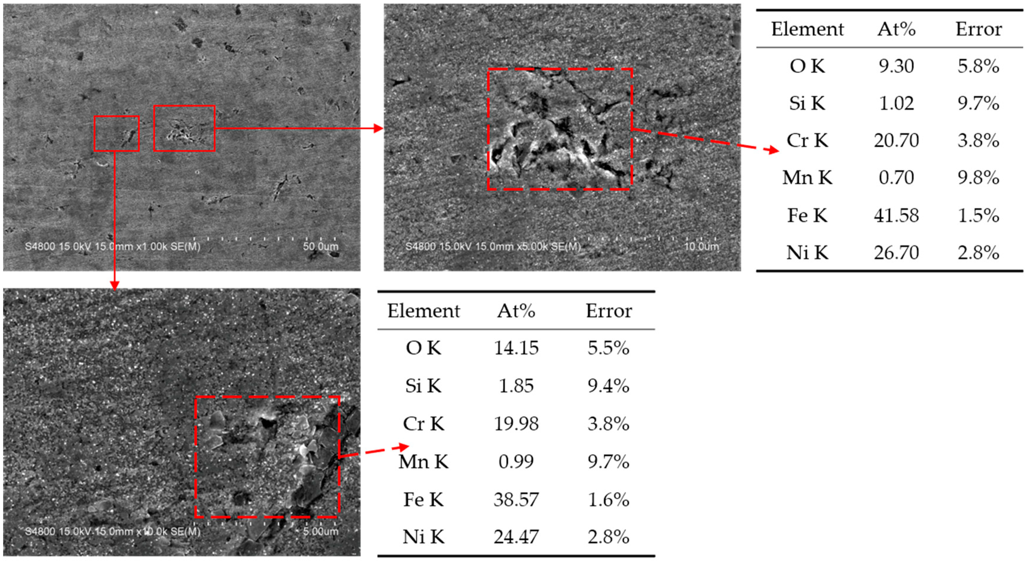
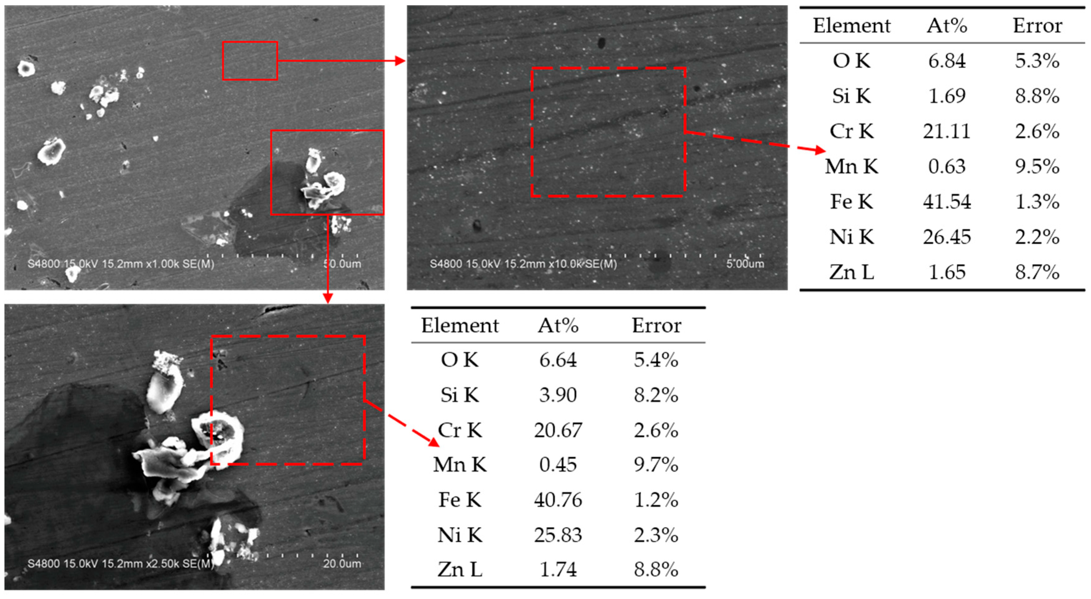
The SEM images and corresponding composition analyses of the passive films formed on 304L with the blank treatment, the zinc treatment and the zinc–aluminum treatment are shown in Figure 8, Figure 9 and Figure 10, respectively.
Many corrosion pits were observed on the surface of the passive film formed on 304L with the blank treatment, as shown in Figure 8. However, the corrosion products were less in quantity than those of A508-3. The correct nickel and chromium contents could be seen from the composition analysis, and the corrosion products in the corrosion pits were mainly oxides of iron, chromium and nickel, thus the oxygen element content significantly increased in the corrosion areas. Typical spinel substances were observed on the surface of the passive film after zinc treatment. According to previous research [18], it could be speculated that this substance might be ZnFe2O4, which has a high stability and enhances corrosion resistance. In addition, the zinc content was approximately 5.5 At% with the zinc treatment. After the zinc–aluminum treatment, a dense sheet-like passive film was formed on the surface of 304L, which could well protect the material from corrosion. The composition analysis showed that both zinc and aluminum were detected and the total amount was approximately 5.2 At%, which was similar to that for the zinc treatment. The content ratio of zinc and aluminum was approximately 1:2, but the total amount was not as high as in A508-3. This demonstrated that aluminum could replace a part of the zinc so as to participate in the film-forming reaction on the 304L‘s surface, however the degree of participation here was weaker than that for A508-3.

3.4.3. In800

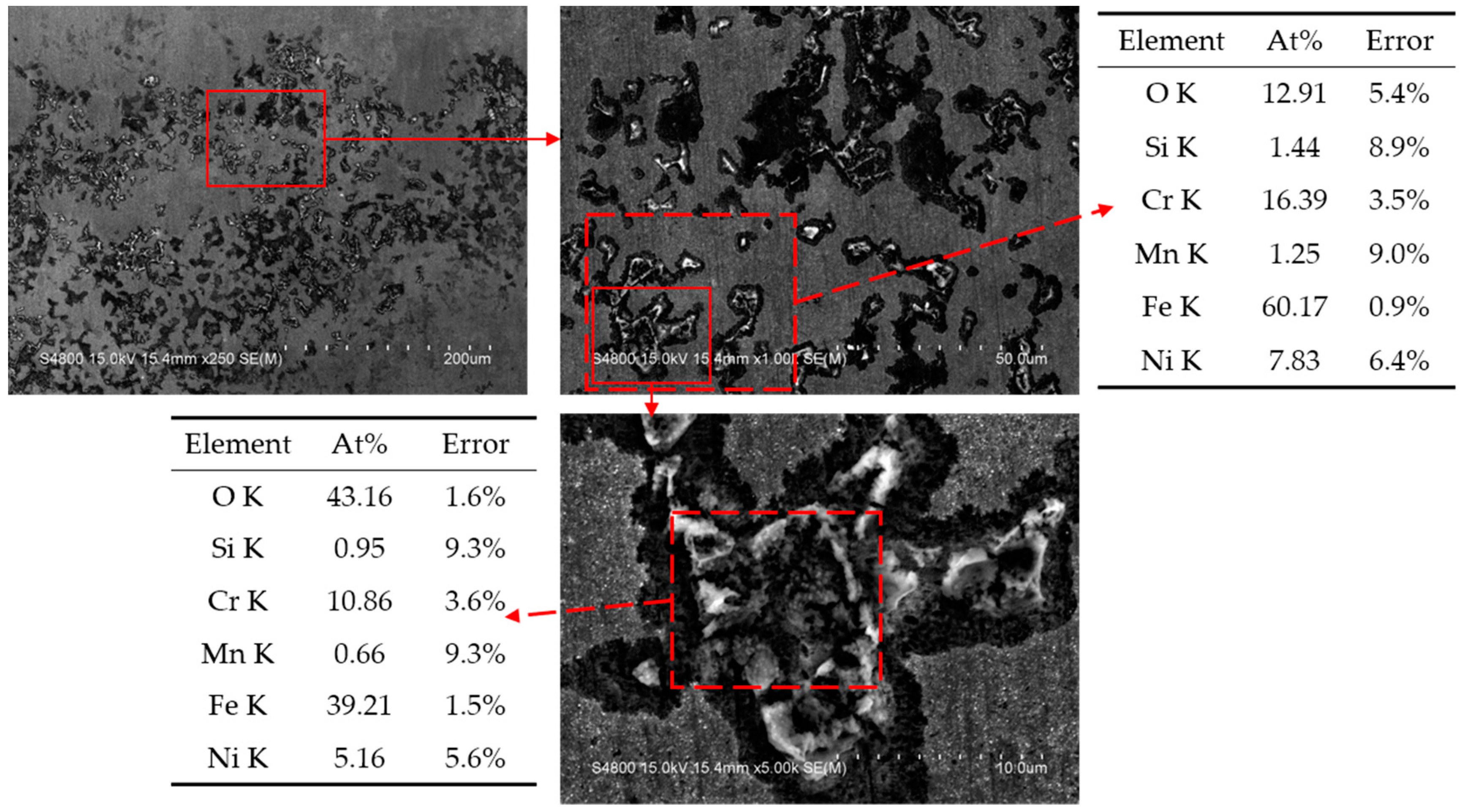
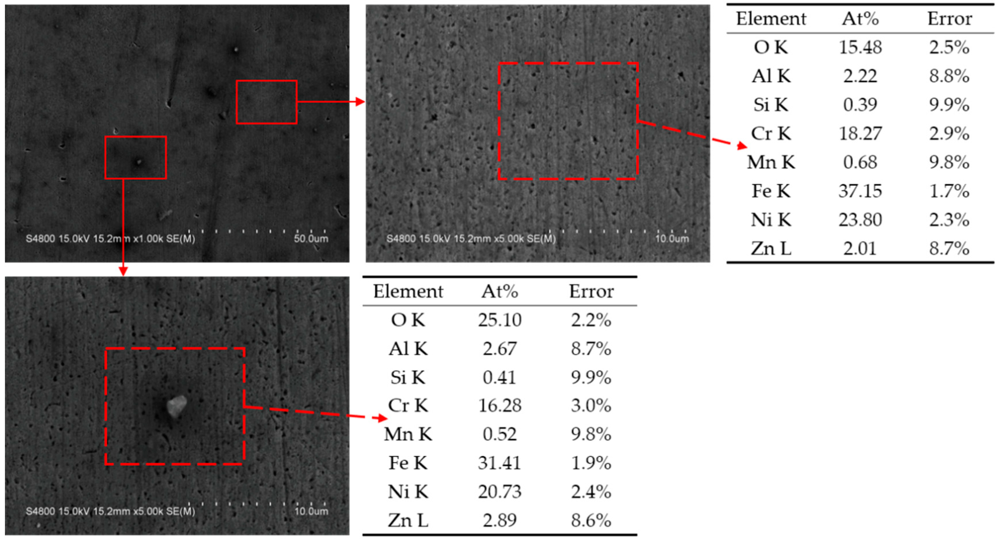
SEM images and the corresponding composition analyses of the passive films formed on In800 with the blank treatment, zinc treatment and zinc–aluminum treatment are shown in Figure 11, Figure 12 and Figure 13, respectively.
The passive film formed on In800 with the blank treatment was smoother and denser than that of the other two materials. However, a few corrosion cracks were also observed. From the composition analysis, it could be found that, due to the characteristics of this material, the contents of nickel and chromium continued to increase compared to those of 304L. After the zinc treatment and zinc–aluminum treatment, the surfaces of the passive films were extremely smooth, and some salt crystals were occasionally observed. The presence of zinc and aluminum was also seen in the composition analysis, but in lesser quantities than in the other two metals. The zinc content of the passive film with the zinc treatment was only about 1.7 At%, however the contents of both elements were more than 2 At% with the zinc–aluminum treatment.
In addition, some typical spinel crystals were observed in the passive films formed on A508-3, 304L and In800 with the zinc–aluminum treatment, as shown in Figure 7, Figure 10 and Figure 13. The crystal observed in Figure 13 was used as an example to perform EDS mapping scanning, and the surface morphology, element distribution and composition analysis are shown in Figure 14.
As shown in Figure 14, the outline of the displayed spinel crystal could be clearly observed in the elemental distribution diagram for oxygen, zinc and aluminum. The majority of the iron, chromium and nickel were distributed on the substrate outside the spinel crystal, which indicated that this spinel crystal was primarily composed of oxygen, zinc and aluminum. In addition, in the composition results, the zinc and aluminum contents were 4.88 At% and 9.43 At%, respectively, which were greatly increased compared to the contents displayed in Figure 13. The content ratio of zinc and aluminum was about 1:2, which was similar to the results for A508-3 and 304L with the zinc–aluminum treatment. These results showed that zinc and aluminum could also undergo compound reactions on the surface of In800, and the reaction products were similar to those of the other two materials; however, the reaction degree here was not as high as it was in the other two materials.

4. Discussion

In the results of the potentiodynamic polarization curves, the corrosion current densities of all three metals with the zinc treatment were greatly reduced. The corrosion current densities of A508-3 and 304L were further reduced after treatment with zinc- aluminum, but this had no clear effect on the In800. In terms of reducing the corrosion current with the zinc–aluminum treatment, A508-3 > 304L > In800. However, due to the high corrosion resistance of In800, its corrosion current density was less than that of the other two metals under any conditions.
The results of the EIS test showed that after treatment with zinc or zinc–aluminum, the impedances of the passive films formed on the three materials were improved to varying degrees. Due to the characteristics of the double-layer structure, the outer film is much less resistant than the inner film. The improvement of the resistance of the passive film with a zinc–aluminum treatment was generally inferior to that achieved with the zinc treatment; however, a significant improvement could still be observed compared to the blank treatment. From the perspective of impedance improvement with the zinc–aluminum treatment, A508-3 > 304L > In800.
The results of the Mott–Schottky curves showed that the zinc treatment and the zinc–aluminum treatment could change the semiconductor properties of the passive films formed on 304L and In800, as clear p-type semiconductor properties appeared in the passivation interval. However, the semiconductor properties of the passive film formed on A508-3 were not changed due to the similar structures of the inner layer and outer layer. Both the zinc treatment and zinc–aluminum treatment decreased the carrier concentration in the passive film formed on A508-3, and negatively shifted the flat band potentials of the passive films formed on 304L and In800. The zinc–aluminum treatment affected the semiconductor properties of the passive films formed on different metals in different ways.
The results of the electrochemical experiments showed that the zinc–aluminum treatment had a significant corrosion-inhibitory effect on A508-3, which was better than that of the zinc treatment. For 304L, the corrosion-inhibition effect of the zinc–aluminum treatment was almost the same as that of the zinc treatment. For In800, the corrosion-inhibition effect of the zinc–aluminum treatment was not as apparent as that of the zinc treatment. In general, the potency of the corrosion-resistance effect of the zinc–aluminum treatment on these three metals was ranked as A508-3 > 304L > In800.
The roughness factor ( R F ) can estimate the roughness of the surface on a passive film, and it can be calculated through Equation (3).
R F = C eff C *
where C eff is the effective electric double-layer capacitance value of the passive film, which can be calculated from the data of the EIS test through the Brug equation, as shown in Table 4. C * is the electric double-layer capacitance value of the smooth surface, which value is 60 μF/cm2 for the smooth passive film containing oxides [41]. The R F values of passive films formed on different materials with different treatment methods are listed in Table 6.
It could be seen from Table 6 and the surface morphologies of the passive films that both the zinc treatment and the zinc–aluminum treatment significantly decreased the roughness of the passive films, and greatly reduced the appearance of corrosion pits on the surfaces of A508-3 and 304L. However, due to the excellent corrosion resistance, In800 experienced no reduction in surface roughness. For A508-3 and 304L, the effect of the zinc–aluminum treatment was similar to that of the zinc treatment, and the increase in the roughness factor of In800 with the zinc treatment was consistent with the presence of inclusions and precipitates on the surface, as shown in Figure 12.
In a large amount of the research on primary circuit zinc injection technology, the main principle of using zinc injection to strengthen the structural material of equipment is the replacement of cobalt with zinc in the passive film, and the generating of the spinel of ZnFe2O4 with a low solubility and high stability, which enhances the corrosion resistance of the passive film [6,9,42,43]. It is speculated from previous research that the zinc–aluminum treatment could generate additional ZnAl2O4 on the surface of the alloy steel, based on the zinc treatment. According to theoretical calculations, this substance has a lower solubility and a stronger stability than ZnFe2O4 [18]. After using the zinc treatment and the zinc–aluminum treatment, the formation of spinel substances with a regular octahedral crystal was observed on the surfaces of passive films; however, the amounts of spinel substances formed on different materials were different. From the results of the polarization curve of In800, the zinc–aluminum treatment had little effect on the enhancement of its corrosion resistance, but small amounts of spinel substances were still formed on its surface. From the composition analysis results of the point scans of the passive films formed on A508-3 and 304L, and the mapping scan of the spinel substances formed on In800, the atomic content ratios of zinc and aluminum were all determined as approximately 1:2. It can be inferred that ZnAl2O4 was formed on all three materials with the zinc–aluminum treatment, but the amount of production was different. The greater the amount of ZnAl2O4 that was produced, the greater the improvement of the corrosion resistance of the material. Therefore, the zinc–aluminum treatment improved the corrosion resistance of A508-3 more so than 304L, and the smallest improvement was offered to In800.
Regular spinel crystals belong to the equiaxed crystal system [44,45,46,47]. The basic structure involves oxygen accumulating in the ABC order perpendicular to the (111) direction. The tetrahedral and octahedral layers are in phase, and the ratio of the number of tetrahedrons to octahedrons is 2:1. The structural formula is XY2O4, where X is a divalent cation, Y is a trivalent cation, trivalent cations occupy octahedral voids, and divalent cations occupy tetrahedral voids [48,49,50,51]. The factors that affect the distributions of elements in the spinel crystals are extremely complex, including the electrostatic energy of ionic bonds, the ionic radius and the crystal field.
According to empirical data, the priority order of the most divalent and trivalent metal ions entering the crystal void can be listed accordingly: Zn2+, Mn2+, Fe3+, Mn3+, Fe2+, Ni3+, Cr3+ [52]. The first ions tend to occupy the tetrahedral voids, and the latter ions tend to occupy the octahedral voids [49,53,54]. The nickel and chromium contents of these three metals are ranked as A508-3 < 304L < In800. According to the ionic order, the presence of chromium and nickel prevents other metal ions from occupying the octahedral voids in the spinel crystals, and prevents the formation of target substances. In other words, high nickel and chromium contents will inhibit the formation of spinel ZnAl2O4 in the passive films on In800, and instead may generate some spinel-type ferrite, such as NixZn1-xFe2O4, which has the same crystal structure as ZnAl2O4 but with inferior stability. Due to the low nickel and chromium contents of A508-3, a large amount of ZnAl2O4 is formed in its passive film, and the corrosion resistance enhancement effect is also more apparent. However, the corrosion resistance of In800 is inherently superior to those ofA508-3 and 304L.
Therefore, it cannot be denied that the zinc–aluminum treatment has excellent corrosion resistance improvement effects on other low nickel and chromium alloys, such as A508-3 and 304L. Compared with zinc treatment technology, this treatment method can reduce the use of depleted zinc, reduce the generation of potential radioactive elements, and save costs.

5. Conclusions

Compared with the zinc treatment, the zinc–aluminum treatment could further reduce the corrosion current density and increase the impedance of the passive films formed on A508-3 and 304L. However, these effects were very weak on In800. The zinc–aluminum treatment changed the semiconductor properties of the passive films formed on 304L and In800, and decreased the carrier concentration of the passive film formed on A508-3. The results of electrochemical experiments showed that the zinc–aluminum treatment significantly improved the corrosion resistance of A508-3, and the corrosion resistance improvement effect on 304L with the zinc–aluminum treatment was similar to that achieved with the zinc treatment. Both the zinc treatment and zinc–aluminum treatment had almost no effect on In800.
According to the morphology and composition analyses, the surfaces of the passive films formed on these three metals became denser and smoother with the formation of spinel crystals after zinc–aluminum treatment. The atomic content ratios of zinc and aluminum were all approximately 1:2, which confirmed that ZnAl2O4 would be generated on all three materials. However, since nickel and chromium would prevent aluminum from participating in the formation of spinel substances in the passive film, the spinel substances generated on the surface of In800 were less in quantity than those formed on 304L, and the most were formed on A508-3. Due to the fact that these three metals behaved very differently under zinc–aluminum treatment, it cannot be recommended that zinc–aluminum treatment provides excellent corrosion resistance enhancement for all metals. This technology requires further research.

Author Contributions

Conceptualization, S.Z.; Data curation, C.S. and J.D.; Formal analysis, C.S. and J.D.; Investigation, C.S. and J.D.; Methodology, S.Z.; Writing: original draft, C.S.; Writing: review and editing, Y.T. All authors have read and agreed to the published version of the manuscript.

Funding

This research was funded by the Fundamental Research Funds for the Central Universities (No. 2018QN092); the Natural Science Foundation of Beijing, China (Grant No. 2192051).

Conflicts of Interest

The authors declare no conflict of interest.

References

  1. Lee, T.H.; Ryu, K.H.; Kim, H.D.; Hwang, I.S.; Kim, J.H.; Lee, M.H.; Choi, S. Effect of oxide film on ECT detectability of surface IGSCC in laboratory-degraded alloy 600 steam generator tubing. Nucl. Eng. Technol. 2019, 51, 1381–1389. [Google Scholar] [CrossRef]
  2. Lin, X.; Peng, Q.; Mei, J.; Han, E.-H.; Ke, W.; Qiao, L.; Jiao, Z. Corrosion of phase and phase boundary in proton-irradiated 308L stainless steel weld metal in simulated PWR primary water. Corros. Sci. 2020, 165, 108401. [Google Scholar] [CrossRef]
  3. Ru, X.; Ma, J.; Lu, Z.; Chen, J.; Han, G.; Zhang, J.; Hu, P.; Liang, X.; Tang, W. Effects of iron content in NiCrFe alloys on the oxide films formed in an oxygenated simulated PWR water environment. J. Nucl. Mater. 2018, 509, 29–42. [Google Scholar] [CrossRef]
  4. Tan, Y.; Yang, J.; Wang, W.; Shi, R.; Liang, K.; Zhang, S. Effects of PbO on the oxide films of incoloy 800HT in simulated primary circuit of PWR. J. Nucl. Mater. 2016, 473, 119–124. [Google Scholar] [CrossRef]
  5. Mohammed, G.R.; Ishak, M.; Aqida, S.N.; Abdulhadi, H.A. Effects of Heat Input on Microstructure, Corrosion and Mechanical Characteristics of Welded Austenitic and Duplex Stainless Steels: A Review. Metals 2017, 7, 39. [Google Scholar] [CrossRef] [Green Version]
  6. Zhang, S.; Shi, R.; Tan, Y. Corrosion behavior of the oxide films modified with zincizing treatment on AISI 1020 steel. J. Alloy. Compd. 2017, 711, 155–161. [Google Scholar] [CrossRef]
  7. Kawamura, H.; Hirano, H.; Katsumura, Y.; Uchida, S.; Mizuno, T.; Kitajima, H.; Tsuzuki, Y.; Terachi, T.; Nagase, M.; Usui, N.; et al. BWR water chemistry guidelines and PWR primary water chemistry guidelines in Japan—Purpose and technical background. Nucl. Eng. Des. 2016, 309, 161–174. [Google Scholar] [CrossRef]
  8. Sawicki, J.A. Analyses of fuel crud and coolant-borne corrosion products in normal water chemistry BWRs. J. Nucl. Mater. 2011, 419, 85–96. [Google Scholar] [CrossRef]
  9. Ziemniak, S.E.; Hanson, M. Zinc treatment effects on corrosion behavior of Alloy 600 in high temperature, hydrogenated water. Corros. Sci. 2006, 48, 3330–3348. [Google Scholar] [CrossRef] [Green Version]
  10. Arjmand, F.; Wang, J.; Zhang, L. Zinc addition and its effect on the corrosion behavior of a 30% cold forged Alloy 690 in simulated primary coolant of pressurized water reactors. J. Alloy. Compd. 2019, 791, 1176–1192. [Google Scholar] [CrossRef]
  11. Hanzawa, Y.; Hiroishi, D.; Matsuura, C.; Ishigure, K. Solubility of zinc ferrite in high-temperature oxygenated water. J. Nucl. Mater. 1998, 252, 209–215. [Google Scholar] [CrossRef]
  12. Zhang, S.; Tan, Y.; Liang, K. Zinc addition changes the semiconductor properties of oxide films of Alloy600 in high temperature water. Mater. Lett. 2012, 68, 36–39. [Google Scholar] [CrossRef]
  13. Liu, X.; Wu, X.; Han, E.-H. Electrochemical and surface analytical investigation of the effects of Zn concentrations on characteristics of oxide films on 304 stainless steel in borated and lithiated high temperature water. Electrochim. Acta 2013, 108, 554–565. [Google Scholar] [CrossRef]
  14. Liu, X.; Wu, X.; Han, E.-H. Influence of Zn injection on characteristics of oxide film on 304 stainless steel in borated and lithiated high temperature water. Corros. Sci. 2011, 53, 3337–3345. [Google Scholar] [CrossRef]
  15. Betova, I.; Bojinov, M.; Kinnunen, P.; Lundgren, K.; Saario, T. Influence of Zn on the oxide layer on AISI 316L(NG) stainless steel in simulated pressurised water reactor coolant. Electrochim. Acta 2009, 54, 1056–1069. [Google Scholar] [CrossRef]
  16. Borisevich, V.D.; Pavlov, A.V.; Okhotina, I.A. Depleted zinc: Properties, application, production. Appl. Radiat. Isot. 2009, 67, 1167–1172. [Google Scholar] [CrossRef] [PubMed]
  17. Kato, M.; Koiwai, M.; Kuwano, J. The aluminium ion as a corrosion inhibitor for iron in water. Corros. Sci. 1979, 19, 937–947. [Google Scholar] [CrossRef]
  18. Zhang, S.; Shi, R.; Chen, Y.; Wang, M. Corrosion behavior of oxide films on AISI 316L SS formed in high temperature water with simultaneous injection of zinc and aluminum. J. Alloy. Compd. 2018, 731, 1230–1237. [Google Scholar] [CrossRef]
  19. Kelm, H.; Glaubitz, U.; Hoffmann, W.; Schlenkrich, H.; Thieme, M. Corrosion product build-up on stainless steel and its influence on hydrazine decomposition.60Co deposition in loop tests using borated water at 300 °C. J. Solut. Chem. 1992, 21, 901–918. [Google Scholar] [CrossRef]
  20. Bandy, R. The simultaneous determination of tafel constants and corrosion rate—A new method. Corros. Sci. 1980, 20, 1017–1028. [Google Scholar] [CrossRef]
  21. Barnartt, S. Two-point and three-point methods for the investigation of electrode reaction mechanisms. Electrochim. Acta 1970, 15, 1313–1324. [Google Scholar] [CrossRef]
  22. McCafferty, E. Validation of corrosion rates measured by the Tafel extrapolation method. Corros. Sci. 2005, 47, 3202–3215. [Google Scholar] [CrossRef]
  23. Taylor, R.J.; Williams, L.F.G. Corrosion Rate Measurements on Steel in Sulfuric Acid Using a Microprocessor Controlled Potentiostat. Corrosion 1980, 36, 41–47. [Google Scholar] [CrossRef]
  24. Stellwag, B. The mechanism of oxide film formation on austenitic stainless steels in high temperature water. Corros. Sci. 1998, 40, 337–370. [Google Scholar] [CrossRef]
  25. Ziemniak, S.E.; Hanson, M. Zinc treatment effects on corrosion behavior of 304 stainless steel in high temperature, hydrogenated water. Corros. Sci. 2006, 48, 2525–2546. [Google Scholar] [CrossRef] [Green Version]
  26. Ziemniak, S.E.; Hanson, M. Corrosion behavior of 304 stainless steel in high temperature, hydrogenated water. Corros. Sci. 2002, 44, 2209–2230. [Google Scholar] [CrossRef] [Green Version]
  27. Ziemniak, S.E.; Hanson, M. Corrosion behavior of NiCrFe Alloy 600 in high temperature, hydrogenated water. Corros. Sci. 2006, 48, 498–521. [Google Scholar] [CrossRef] [Green Version]
  28. Alves, V.A.; Brett, C.M.A. Characterisation of passive films formed on mild steels in bicarbonate solution by EIS. Electrochim. Acta 2002, 47, 2081–2091. [Google Scholar] [CrossRef] [Green Version]
  29. Rodríguez, M.n.A.; Carranza, R.M. Properties of the Passive Film on Alloy 22 in Chloride Solutions Obtained by Electrochemical Impedance. J. Electrochem. Soc. 2011, 158, C221. [Google Scholar] [CrossRef]
  30. Martini, E.M.A.; Muller, I.L. Characterization of the film formed on iron in borate solution by electrochemical impedance spectroscopy. Corros. Sci. 2000, 42, 443–454. [Google Scholar] [CrossRef]
  31. Brug, G.J.; van den Eeden, A.L.G.; Sluyters-Rehbach, M.; Sluyters, J.H. The analysis of electrode impedances complicated by the presence of a constant phase element. J. Electroanal. Chem. Interfacial Electrochem. 1984, 176, 275–295. [Google Scholar] [CrossRef]
  32. Hirschorn, B.; Orazem, M.E.; Tribollet, B.; Vivier, V.; Frateur, I.; Musiani, M. Determination of effective capacitance and film thickness from constant-phase-element parameters. Electrochim. Acta 2010, 55, 6218–6227. [Google Scholar] [CrossRef]
  33. Harrington, S.; Devine, T. Relation Between the Semiconducting Properties of a Passive Film and Reduction Reaction Rates. J. Electrochem. Soc. 2009, 156, C154–C159. [Google Scholar] [CrossRef]
  34. Vetter, K. Electrochemical Kinetics: Theoretical and Experimental Aspects; Academic Press: New York, NY, USA, 1967. [Google Scholar]
  35. Gomes, W.P.; Vanmaekelbergh, D. Impedance spectroscopy at semiconductor electrodes: Review and recent developments. Electrochim. Acta 1996, 41, 967–973. [Google Scholar] [CrossRef]
  36. Tsuchiya, H.; Fujimoto, S.; Chihara, O.; Shibata, T. Semiconductive behavior of passive films formed on pure Cr and Fe–Cr alloys in sulfuric acid solution. Electrochim. Acta 2002, 47, 4357–4366. [Google Scholar] [CrossRef]
  37. Kim, Y.S.; Kim, J.G. Corrosion Behavior of Pipeline Carbon Steel under Different Iron Oxide Deposits in the District Heating System. Metals 2017, 7, 182. [Google Scholar] [CrossRef]
  38. Ahn, S.J.; Kwon, H.S. Effects of solution temperature on electronic properties of passive film formed on Fe in pH 8.5 borate buffer solution. Electrochim. Acta 2004, 49, 3347–3353. [Google Scholar] [CrossRef]
  39. Hamadou, L.; Kadri, A.; Benbrahim, N. Characterisation of passive films formed on low carbon steel in borate buffer solution (pH 9.2) by electrochemical impedance spectroscopy. Appl. Surf. Sci. 2005, 252, 1510–1519. [Google Scholar] [CrossRef]
  40. Feng, Z.; Cheng, X.; Dong, C.; Xu, L.; Li, X. Passivity of 316L stainless steel in borate buffer solution studied by Mott–Schottky analysis, atomic absorption spectrometry and X-ray photoelectron spectroscopy. Corros. Sci. 2010, 52, 3646–3653. [Google Scholar] [CrossRef]
  41. Levine, S.; Smith, A. Theory of the Differential Capacity of the Oxide/Aqueous Electrolyte Interface. Discuss. Faraday Soc. 1971, 52. [Google Scholar] [CrossRef]
  42. Kawamura, H.; Shirai, S.; Matsunaga, T.; Oshinden, K.; Takiguchi, H.; Yamaoka, K.; Takamatsu, H.; Hirano, H. Inhibitory Effect of Zinc Addition to High-Temperature Hydrogenated Water on Mill-Annealed and Prefilmed Alloy 600. Corrosion 2000, 56. [Google Scholar] [CrossRef]
  43. Kim, H.-S.; Lee, H.B.; Chen, J.; Jang, C.; Kim, T.S.; Stevens, G.L.; Ahluwalia, K. Effect of zinc on the environmentally-assisted fatigue behavior of 316 stainless steels in simulated PWR primary environment. Corros. Sci. 2019, 151, 97–107. [Google Scholar] [CrossRef]
  44. Han, M.; Wang, Z.; Xu, Y.; Wu, R.; Jiao, S.; Chen, Y.; Feng, S. Physical properties of MgAl2O4, CoAl2O4, NiAl2O4, CuAl2O4, and ZnAl2O4 spinels synthesized by a solution combustion method. Mater. Chem. Phys. 2018, 215, 251–258. [Google Scholar] [CrossRef]
  45. Inoue, M.; Otsu, H.; Kominami, H.; Inui, T. ChemInform Abstract: Synthesis of Double Oxides Having Spinel Structure (ZnAl2O4, ZnGa2O4) by the Glycothermal Method. ChemInform 1991, 22. [Google Scholar] [CrossRef]
  46. Stringhini, F.M.; Foletto, E.L.; Sallet, D.; Bertuol, D.A.; Chiavone-Filho, O.; Nascimento, C.A. Synthesis of porous zinc aluminate spinel (ZnAl2O4) by metal-chitosan complexation method. J. Alloy. Compd. 2014, 588, 305–309. [Google Scholar] [CrossRef]
  47. Cao, L.; Wang, G.C.; Yuan, X.H.; Jin, P.L.; Sridhar, S. Thermodynamics and Agglomeration Behavior on Spinel Inclusion in Al-Deoxidized Steel Coupling with Mg Treatment. Metals 2019, 9, 900. [Google Scholar] [CrossRef] [Green Version]
  48. Levy, D.; Pavese, A.; Sani, A.; Pischedda, V. Structure and compressibility of synthetic ZnAl2O4 (gahnite) under high-pressure conditions, from synchrotron X-ray powder diffraction. Phys. Chem. Miner. 2001, 28, 612–618. [Google Scholar] [CrossRef]
  49. Gorla, C.; Mayo, W.; Liang, S.; Lu, Y. Structure and Interface-Controlled Growth Kinetics of ZnAl2O4 Formed at the (1120) ZnO/(0112) Al2O3 Interface. J. Appl. Phys. 2000, 87, 3736–3743. [Google Scholar] [CrossRef]
  50. Khenata, R.; Sahnoun, M.; Baltache, H.; Rérat, M.; Reshak, A.H.; Al-Douri, Y.; Bouhafs, B. Full-potential calculations of structural, elastic and electronic properties of MgAl2O4 and ZnAl2O4 compounds. Phys. Lett. A 2005, 344, 271–279. [Google Scholar] [CrossRef]
  51. Liu, L.; Chen, M.; Xu, L.; Yin, X.L.; Sun, W.J. Effect of BaO Addition on Densification and Mechanical Properties of Al2O3-MgO-CaO Refractories. Metals 2016, 6, 84. [Google Scholar] [CrossRef] [Green Version]
  52. Davey, W.P. An Introduction to Crystal Chemistry (Evans, R.C.). J. Chem. Educ. 1940, 17, 451. [Google Scholar] [CrossRef] [Green Version]
  53. Kamada, K.; Shoji, Y.; Yamaji, A.; Kurosawa, S.; Yokota, Y.; Ohashi, Y.; Kim, K.J.; Ivanov, M.; Kochurikhin, V.V.; Yoshikawa, A. Melt growth of zinc aluminate spinel single crystal by the micro-pulling down method under atmospheric pressure. J. Cryst. Growth 2018, 492, 67–70. [Google Scholar] [CrossRef]
  54. D’Ippolito, V.; Andreozzi, G.; Bosi, F.; Hålenius, U.; Mantovani, L.; Bersani, D.; Fregola, R. Crystallographic and spectroscopic characterization of a natural Zn-rich spinel approaching the endmember gahnite (ZnAl2O4) composition. Mineral. Mag. 2013, 77, 2941–2953. [Google Scholar] [CrossRef]
Figure 1. The polarization curves in semilogarithmic coordinates of the passive films formed on (a) A508-3, (b) 304L and (c) In800 with different treatment method.
Metals 10 00986 g001
Figure 2. The EIS of the passive films formed on different materials with different treatment methods: (a) A508-3, Nyquist diagram; (b) A508-3, Bode diagram; (c) 304L, Nyquist diagram; (d) 304L, Bode diagram; (e) In800, Nyquist diagram; (f) In800, Bode diagram.
Metals 10 00986 g002
Figure 3. The electrical equivalent circuit diagram of passive film: (a) for A508-3; and (b) for 304L and In800.
Metals 10 00986 g003
Figure 4. The Mott–Schottky curves of the passive films formed on (a) A508-3, (b) 304L and (c) In800 with different treatment methods.
Metals 10 00986 g004
Figure 5. Scanning electron microscope (SEM) images and the corresponding composition analysis of the passive film formed on A508-3 with the blank treatment.
Metals 10 00986 g005
Figure 6. SEM images and the corresponding composition analysis of the passive film formed on A508-3 with the zinc treatment.
Metals 10 00986 g006
Figure 7. SEM images and the corresponding composition analysis of the passive film formed on A508-3 with the zinc–aluminum treatment.
Metals 10 00986 g007
Figure 8. SEM images and the corresponding composition analysis of the passive film formed on 304L with the blank treatment.
Metals 10 00986 g008
Figure 9. SEM images and the corresponding composition analysis of the passive film formed on 304L with the zinc treatment.
Metals 10 00986 g009
Figure 10. SEM images and the corresponding composition analysis of the passive film formed on 304L with the zinc–aluminum treatment.
Metals 10 00986 g010
Figure 11. SEM images and the corresponding composition analysis of the passive film formed on In800 with the blank treatment.
Metals 10 00986 g011
Figure 12. SEM images and the corresponding composition analysis of the passive film formed on In800 with the zinc treatment.
Metals 10 00986 g012
Figure 13. SEM images and the corresponding composition analysis of the passive film formed on In800 with the zinc–aluminum treatment.
Metals 10 00986 g013
Figure 14. The Surface morphology, element distribution and composition analysis of the observed crystal formed on materials with the zinc–aluminum treatment.
Metals 10 00986 g014
Table 1. The elemental composition of A508-3 steel (A508-3), 304L stainless steel (304L) and Incoloy 800 alloy (In800).
MaterialsCSiMnPSCrNiMoCuFe
A508-30.220.2281.390.0120.0030.1220.0680.540.117Bal.
304L0.030.521.030.0170.00618.019.60--Bal.
In8000.040.851.500.0300.01521.2032.50-0.3Bal.
Table 2. The ionic compositions of the experimental solutions.
GroupB (ppm)Li (ppm)Zn (mol/L)Al (mol/L)
G(blank)2501.1--
G(Zn)2501.10.24-
G(Zn + Al)2501.10.120.12
Table 3. The corrosion current (Icorr) and corrosion potential (Ecorr) of the passive films formed on A508-3, 304L and In800 with different treatment methods.
GroupA508-3304LIn800
Icorr (A/cm2)Ecorr (V)Icorr (A/cm2)Ecorr (V)Icorr (A/cm2)Ecorr (V)
G(blank)(2.27 ± 0.13) × 10−5−0.37 ± 0.06(1.23 ± 0.13) × 10−6−0.14 ± 0.06(5.74 ± 0.08) × 10−8−0.26 ± 0.04
G(Zn)(2.82 ± 0.09) × 10−6−0.59 ± 0.04(4.17 ± 0.18) × 10−7−0.42 ± 0.08(5.09 ± 0.12) × 10−8−0.27 ± 0.03
G(Zn + Al)(2.19 ± 0.12) × 10−6−0.55 ± 0.05(2.82 ± 0.08) × 10−7−0.17 ± 0.03(9.31 ± 0.10) × 10−8−0.22 ± 0.04
Table 4. The fitting parameters of the electrochemical impedance spectroscopy (EIS) test.
GroupRs
(Ω/cm2)
Qout ( C eff ) out ( μ F / cm 2 ) Rout
(Ω/cm2)
L
(H/cm2)
Qin ( C eff ) in ( μ F / cm 2 ) Rin
(Ω/cm2)
Y(secn/cm2)nY(secn/cm2)n
A508-3G(blank)4.112.36 × 10−40.5535.72 × 10042.55.89 × 10−67.67 × 10−40.936911.21.62 × 104
G(Zn)1.039.92 × 10−60.5937.58 × 10−283.13.35 × 10−131.96 × 10−40.811561.04.65 × 105
G(Zn + Al)5.021.43 × 10−70.9719.84 × 10−225.74.81 × 10−101.29 × 10−40.729459.32.36 × 105
304LG(blank)5.098.12 × 10−60.9444.82 × 10019.0-7.85 × 10−50.801331.74.21 × 106
G(Zn)7.468.37 × 10−90.9897.10 × 10−343.7-3.30 × 10−50.89083.05.29 × 107
G(Zn + Al)1.086.70 × 10−91.0006.70 × 10−341.6 7.26 × 10−50.808120.81.16 × 107
In800G(blank)5.943.56 × 10−80.8745.24 × 10−347.4-9.53 × 10−60.947119.55.99 × 106
G(Zn)4.763.17 × 10−50.8621.29 × 10−1114.0-1.06 × 10−30.7591920.18.66 × 106
G(Zn + Al)8.715.76 × 10−91.0005.76 × 10-342.1-5.27 × 10−50.806219.37.17 × 106
Table 5. The n-type semiconductor parameters of the passive films formed on A508-3, 304L and In800 with different treatment methods.
GroupA508-3304LIn800
N (cm−3) E f b   ( V ) N (cm−3) E f b   ( V ) N (cm−3) E f b   ( V )
G(blank)(7.71 ± 0.21) × 1020−0.72 ± 0.04(2.61 ± 0.09) × 1020−0.23 ± 0.02(1.64 ± 0.11) × 1020−0.25 ± 0.03
G(Zn)(4.50 ± 0.19) × 1019−0.51 ± 0.04(4.34 ± 0.39) × 1020−2.90 ± 0.12(1.75 ± 0.10) × 1020−1.34 ± 0.05
G(Zn + Al)(3.43 ± 0.12) × 1019−0.41 ± 0.02(1.41 ± 0.15) × 1020−0.65 ± 0.04(2.26 ± 0.13) × 1020−1.62 ± 0.07
Table 6. The R F values of passive films formed on different materials with different treatment methods.
GroupA508-3304LIn800
G(blank)15.25.52.0
G(Zn)9.31.432.0
G(Zn + Al)7.62.03.6