Article

Mechanisms of Oxidation Degradation of Cr12 Roller Steel during Thermal Fatigue Tests

1
Faculty of Natural Sciences and Engineering, University of Ljubljana, 1000 Ljubljana, Slovenia
2
Department of Materials Science and Metallurgy, University of Cambridge, Cambridge CB3 0FS, UK
3
Department of Mechanical and Aerospace Engineering, NSIRC, Brunel University London, Cambridge CB21 6AL, UK
4
Mechanical and Marine Engineering Laboratory, Marine Research Institute, Klaipėda University, 92294 Klaipėda, Lithuania
5
Faculty of Marine Technology and Natural Sciences, Klaipėda University, 91225 Klaipėda, Lithuania
*
Authors to whom correspondence should be addressed.
Metals 2020, 10(4), 450; https://doi.org/10.3390/met10040450
Submission received: 3 March 2020 / Revised: 23 March 2020 / Accepted: 24 March 2020 / Published: 28 March 2020
(This article belongs to the Special Issue Thermal Fatigue Behavior of Roller Steel)

Abstract

:
Degradation by the penetration of oxidation into the Cr12 roller steel is evaluated during thermal fatigue tests in the laboratory in the temperature range of 500–700 °C. A qualitative assessment is carried out with regard to the thermal load, the microstructure and the test temperature. The results show that the specific properties of the microstructure with respect to thermal stress and temperature have a significant influence on the oxidation behavior as well as on the crack propagation mode and crack growth. The conditions that lead to an increase in the oxidation rate and thus to premature and sudden local chipping of the roll surface layer are analyzed and explained.

1. Introduction

Hot rolling is the most important bulk forming process. The central tools in this mass forming process are work rolls (steel rollers), which account for up to 15% of the manufacturing costs [1,2]. During operation, rollers are exposed to a deterioration of the surface layer, which affects the surface quality of the rolled products. High manufacturing costs make any attempts to increase the operating time of the rolls and improve the surface quality of the rolled products enticing [2,3,4]. The oxidation process of rolls has a strong influence on the complex degradation process of the roll surface layer [4,5,6,7,8,9,10,11,12,13]. The degradation of the roller surface is related to the microstructure, the temperature and the thermal stresses acting on it. The oxidation behavior of the roll surface is an important degradation mechanism. It is generally very complex, as temperature, time, environmental conditions and microstructure are intertwined [3,5,6,7,8,9,10,11,12,13,14,15,16,17,18,19,20,21,22,23,24,25,26,27,28,29,30,31,32,33,34]. The oxidation behavior of roller material at high temperatures was investigated by oxidation studies [4,15,22,23,28,34,35,36,37,38], tribological tests [3,9,10,11,14,16,25,26,33,35,39,40,41,42,43,44,45,46,47,48,49,50,51,52,53,54,55,56,57] and thermal fatigue tests [5,6,12,29,30,31]. The tribological tests were performed with disc-on-disc tests [3,9,10,11,16,24,25,26,32,35,39,40,41,42,43,44,45,46,47,48,49,50,57] or pin-on-disc tests [14,16,28,51,52,53,54,55]. The aim was to evaluate: the wear behavior of cast, high-speed steel roller material; lubricants; the influence of C and Cr contents on wear resistance and surface roughness; and the wear and friction behavior of high speed steel, ledeburitic steel and cast iron with high Cr content, etc. The tribological tests were performed at high temperatures and under isothermal conditions.
Hanlon et al. [45] and Molinari et al. [15] observed the oxide penetration into the material at the carbide/matrix interface. However, their studies do not focus on oxidation penetration in connection with microstructure, temperature and thermal stress. In addition, Lao et al. [27] argue that the condition under isothermal testing in the highly plastic deformed area during sliding wear is not comparable with the behavior during hot rolling. Since these interrelationships are not sufficiently explained, it is essential to carry out research in this area in order to improve our knowledge of the aforementioned interrelated influences and mechanisms.
Numerous oxidation studies have been performed in different atmospheres at high temperatures [4,15,22,23,28,34,36,37,38]. Different oxidation rates of the matrix and the carbides were determined depending on the test temperature, the material, the carbide properties and the atmosphere (oxidation conditions). Contrary to the general assumption, Kim et al. [34] argue that carbides oxidize faster than the matrix in a dry atmosphere and that the oxides on the surface of the oxidized matrix become larger. In addition, different oxidation rates were observed for the different carbide types in the matrix, which is the basis for the formation of relatively small oxidation tongues. In the studies [5,6,12,29,30,31] thermal fatigue tests were used to demonstrate that oxidation accelerates crack growth and other degradation processes (i.e., chipping and spalling). However, the oxidation penetration was not investigated. Colas et al. [7] showed an accentuated oxidation penetration in high Cr roller material, but they did not explain the reasons for this behavior. This can be attributed to a strong water cooling of the heated material. Garza-Montes-de-Oca et al. [39] showed that an increased presence of water leads to an increased oxidation rate.
The lack of results that explain the degradation processes due to oxidation penetration can be attributed to the laboratory test conditions used. In real industrial settings, temperatures during heating reach or even exceed 700 °C. This is followed by intensive water cooling, generating a large amount of steam. Conditions found in the laboratory often do not reproduce the severe conditions found in industry. Our thermal fatigue testing setup [5,6], has the advantage of an extremely precise temperature control with computer controlled heating and cooling, resulting in a constant temperature field of all cycles from the first to the last. This enabled the repeatability of thermal fatigue tests, wherein quantitative analysis of degradation by thermal cycles showed that oxidation penetration can have a significant influence on the degradation progress of the roller material surface. Therefore, it is important to analyze the behavior of the oxidation penetration in detail with regard to thermal stresses, microstructure and test temperature.
In this paper missing knowledge about oxidation penetration in relation to microstructural properties, test temperature and thermal stresses that influence the subsequent spalling of the roller material are presented, analyzed and discussed. The qualitative analysis of the oxidation behavior and the relationship with the microstructure, the test temperature and the numerically determined thermal stresses was carried out with the aim of better understanding the relationships between oxidation, microstructure and thermal stress states.

2. Materials and Methods

The material used in this study was a centrifugally cast roller shell of a high Cr steel with chemical composition given in Table 1. Thermal fatigue tests were conducted using the Gleeble 1500D (Dynamic Systems Inc., Poestenkill, NY, USA) thermomechanical simulator at three maximum test temperatures (500, 600 and 700 °C) and a finite number of thermal cycles (200, 500, 1000 and 2500 cycles) for each test temperature. Conductive heating and water cooling by the borehole sample were carried out cyclically according to a temperature program that replicates the conditions obtained on the roll surface during hot rolling. A detailed description of the test rig is given in [5], while detailed qualitative and quantitative properties of thermal fatigue resistance for the same material are given in [6].
After the thermal fatigue test, the working lengths of each specimen were first cut in the axial direction through the center and one half also in the radial direction for microscopy. The characterization of cracks was focused within the working length of the specimen. Optical microscopy (Zeiss AXIO Imager.A1m, Carl Zeiss Microscopy GmbH, Jena, Germany) and scanning electron microscopy (JEOL 5610, JEOL Ltd., Tokyo, Japan and FEI Nova NanoSEM, FEI Europe B.V., Eindhoven, Netherlands) were used to observe the microstructure and the damage developed after a finite number of thermal cycles. The surfaces for microstructural evaluation were ground, polished and etched with 3 vol. % Nital solution. The SEM microscopy was combined with the attached energy dispersive X-ray spectroscopy (EDX) for elemental mapping of the microstructure.

3. Results

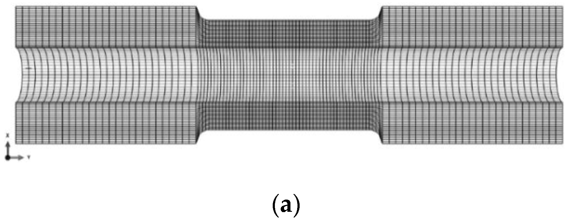
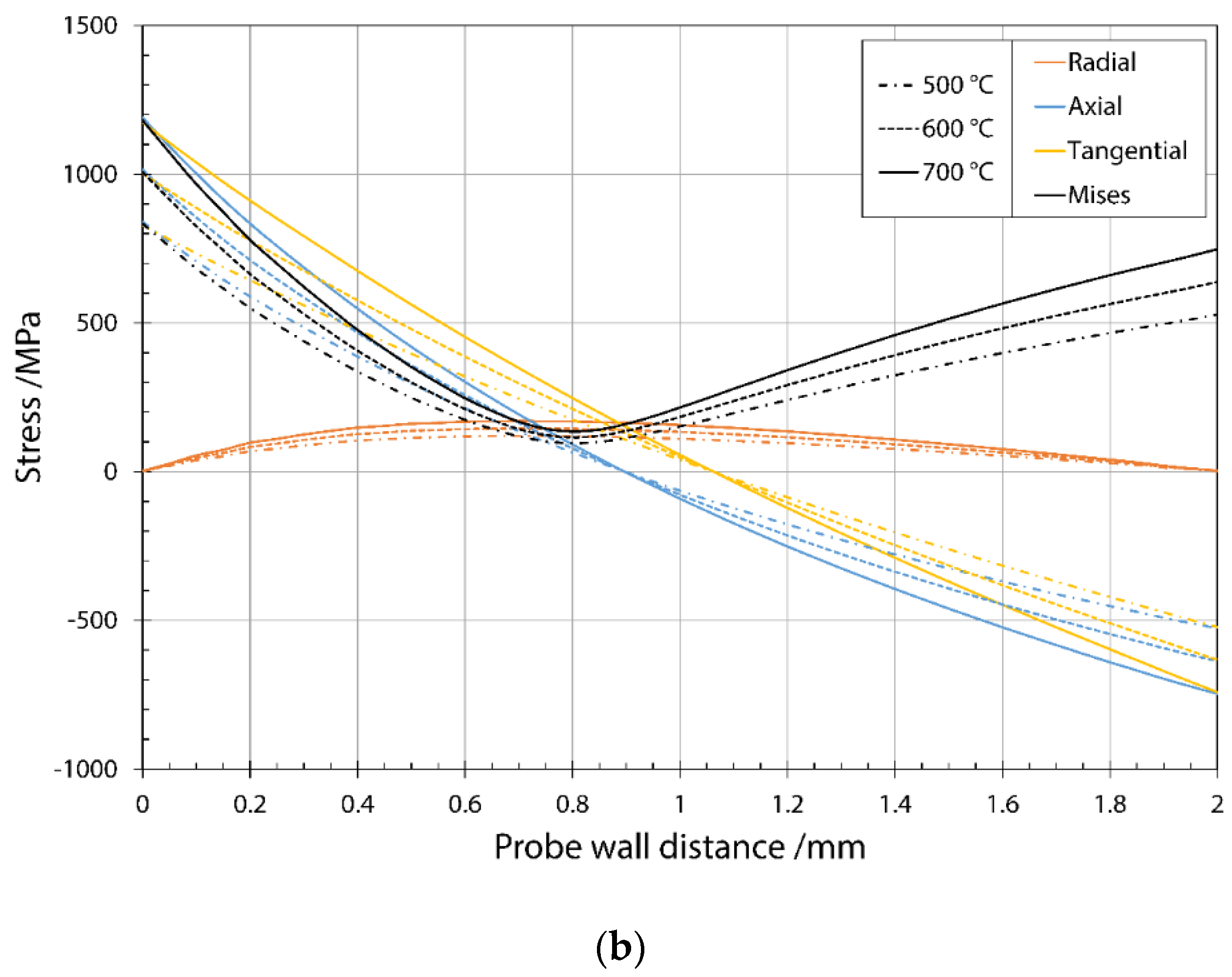
3.1. Stress Distribution during Thermal Fatigue Cycle

The elastic stress distribution during the thermal fatigue cycle was determined by a finite element model created in the Abaqus 2018 (Dassault Systèmes Simulia Corp., Johnston, RI, USA) software. The purposes of the finite element analysis were to determine the stress distributions in the samples under thermal load and to find out which stress component was the strongest and could possibly contribute to crack initiation. The finite element mesh is shown in Figure 1a, and it is a borehole sample with an outer diameter of 8 mm and a wall thickness of 2 mm at the measurement cross gauge section. The diameter of the inner bore is 4 mm.
Steady state coupled displacement-temperature analysis was carried out. This type of analysis allows one to solve the displacement field as a result of the applied temperature. In the model, the temperature was applied as a boundary condition to the outer and inner surfaces of the sample. The inner and outer surfaces were subjected to a temperature boundary condition of 20 °C and a test temperature (500, 600 and 700 °C). The movement of the probe was not restricted in any direction. In the model the quadratically coupled temperature-displacement element type C3D20T was used. The material constants used were as follows: modulus of elasticity 200 GPa, Poisson′s ratio 0.3, coefficient of thermal expansion 11 × 10−6 K−1, coefficient of thermal conductivity 26 Wm−1 K–1, specific heat 460 Jm−1 K−1 and density 7800 kg m−3.
The stress values along the wall thickness were extracted using a cylindrical coordinate system, where the x-axis corresponds to the radial direction, the y-axis to the axial and the z-axis to the tangential (cf. Figure 1a). The sample wall was divided into 20 elements with a uniform thickness of 100 μm. By selecting the fully integrated element type C3D20T, the center plane of each element is also available for stress extraction. It enabled the extraction of stress values at element nodes located at 50 μm. The results obtained for stress are summarized in Figure 1b.
Radial stresses reached a maximum value of 170 MPa at a temperature of 700 °C at the depth of 700 μm. Another important finding is that longitudinal stresses on the inner surface of the specimen are positive and generate stress forces, which primarily contributes to crack initiation. The maximum axial stress has a value of 1180 MPa on the inner surface. At the depth of 900 μm the axial stresses change their orientation and become compressive. The results obtained show that there are favorable conditions for the initiation of surface or near-surface cracks. High axial stresses contribute to the initiation of transverse cracks and radial stresses to the initiation of longitudinal cracks. In the earlier work of the same authors [6] it was shown that transverse cracks are apparently more severe.

3.2. Initial Microstructure

The analysis of the initial microstructure of the same material was described in detail in reference [6]. To summarize the published results, quantitative metallography of roller material with high Cr content yielded 15.46 vol. % M7C3 and 1.41 vol. % M2C carbides and a measured hardness of 601 ± 10 HV10. Based on these results, Figure 2a,b shows a backscatter secondary electron (BSE) micrograph and the elemental distribution of Mo. Building upon XRD analysis presented in the previous study [6], EDX chemical mapping analysis helped to identify Mo-based carbides identified as M2C (cf. Figure 2b). Distribution of Mo shows an areas enriched with Mo in carbides.
The approximate chemical compositions of the carbides present in the roller material, as determined by EDX, are shown in Table 2. Reduced Cr content was observed in a narrow band approximately 4 μm wide adjacent to the carbide/matrix boundary for the primary carbide shown in Figure 3a and the line distribution of the elements in Figure 3b. Compared to an approximate Cr content of 7–9 wt. % elsewhere in the matrix, the Cr content within this band was measured at only 4–5 wt. % (see Table 2). Similar results were obtained for the eutectic carbide matrix (see Figure 3c,d). It is also worth noting that the detected content of Mo in primary carbides (3–8 wt. %) is increased compared to the content in eutectic carbides (2.1–2.9 wt. %). On the other hand, the Cr content in primary carbides is slightly lower (42–50 wt. %) compared to the content in eutectic carbides (44–52 wt. %). The values obtained for the V content in eutectic and primary carbides were in the range of 1.5–1.9% by weight, while the V content in the matrix was about 0.1% by weight (see Table 2).

3.3. Oxidation Behaviour and Its Relationship between Microstructure, Thermal Stress and Temperature

With regard to the observed oxidation behavior during thermal fatigue testing of the roller material made of high Cr steel, the following properties are relevant; (i) chemical compositions of primary and eutectic carbides, matrix material, band at the carbide/matrix interface adjacent to primary and eutectic carbides; oxidation progress; (ii) sizes, shapes and orientations of the carbides; their crushing and cracking; crack propagation direction; oxidation behavior at high thermal stresses and (iii) oxidation behavior at low thermal stresses; (iv) direction of the applied effective thermal stress and oxidation direction in the matrix; (v) microcracks around the crack tip and oxidation of the crack tip; (vii) uncracked eutectic carbides and oxidation progress (oxidation of carbides or eutectic matrix); (viii) cracked eutectic carbides and oxidation progress; (ix) orientation of eutectic carbide lamellae, thermal stress and oxidation progress; (x) temperature influence on oxidation; (xi) properties of eutectic and primary carbides (arrangement, orientation, size, shape) and cases of significant oxidation area.
During thermal fatigue, the samples were cooled with water. Thus the current test approaches the conditions that occur on the surface of work rolls in rolling mills. Furthermore, it allows the observation of the particularly pronounced oxidation cases presented in this study and enabled us to explain the wear behavior.

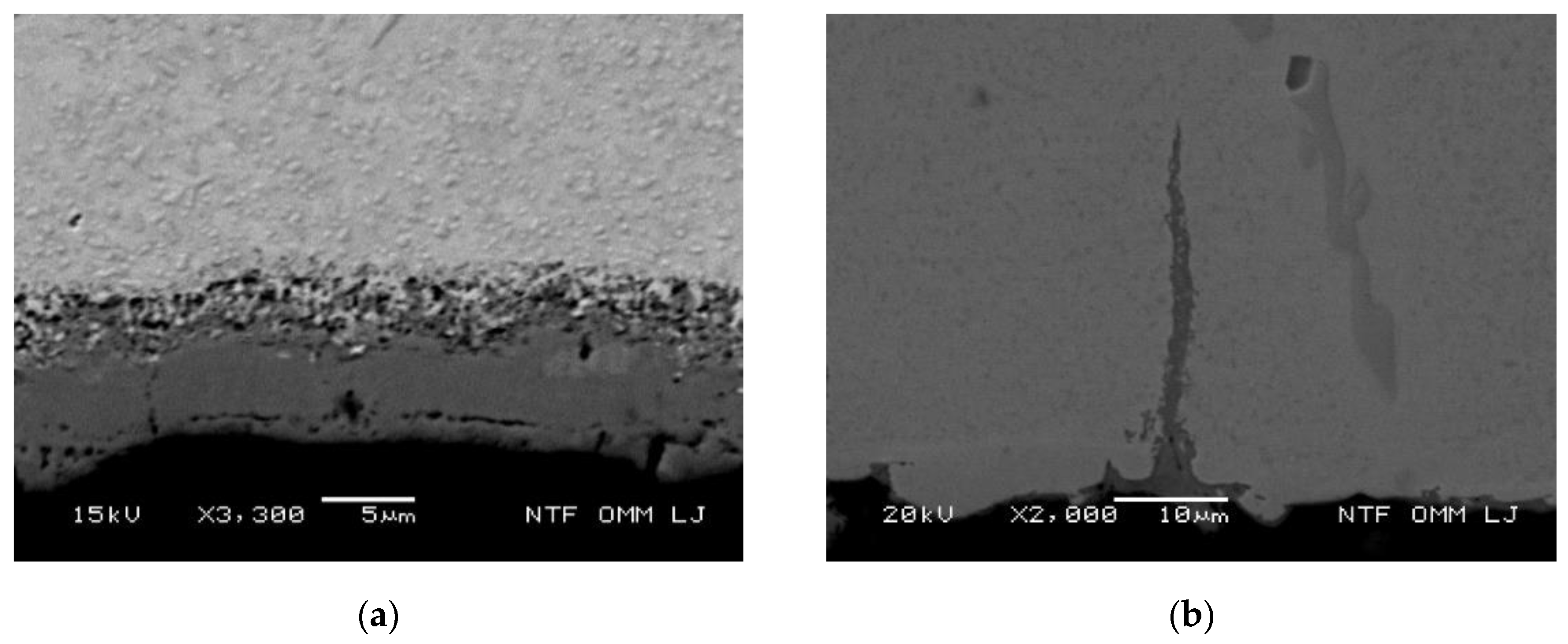
3.3.1. Oxidation Behavior of Uncracked Carbides

The first interesting case observed was the oxidation of material between the islands of the eutectic carbide cluster. The eutectic cluster shown in Figure 4a is located about 400 µm below the cooled surface. The results of the FEM simulations show that the applied thermal stress (axial) during the temperature changes at this depth is 1180 MPa at 700 °C. Figure 4a shows that after 2500 thermal cycles a partial oxidation of the matrix between eutectic carbides cluster occurred as a result of thermal stress. However, the carbide lamellae of the carbides are not cracked and no oxidation of the carbides was observed, at least in the central part. However, this happened on a small area, as can be seen in the lower part of the eutectic carbide cluster. The element maps in Figure 4b,c show the distributions of Cr and Mo. Additional confirmation of the oxidized matrix is shown with the distribution of oxygen in Figure 4d. Qualitatively, the oxidation rate between carbides and matrix can be estimated by detailed examination of the superimposed Figure 4a,d. Oxidation occurs first in the narrow band at the carbide/matrix interface, whereas eutectic carbides are not oxidized. In addition, a small area in the lower and slightly right part of the eutectic in Figure 4a shows complete oxidation (see Figure 4d), in which matrix and carbides are oxidized. From this it can be confirmed that the oxidation starts in the matrix and has a higher rate compared to the carbide. This finding is important and helps to explain the changes required at the transition from the carbide pathway to the matrix pathway.

3.3.2. Oxidation Behavior of Cracked Eutectic Carbides at and Close to the Surface

The elastic thermal stresses on the cooled surface were calculated to be 833 MPa at 500 °C, 1010 MPa at 600 °C and 1180 MPa at 700 °C. Primary and eutectic carbides located on the cooled surface decompose during thermal fatigue and initially show transverse cracks, as shown in Figure 5a and a detailed view at higher magnification in Figure 5b. The crack shown cuts through carbides and matrix and represents a way in which oxygen penetrates eutectic carbides and causes accelerated oxidation.
Figure 5c,d shows the oxidation taking place on a cracked carbide, the crack being connected to the cooled surface and the oxidation being visible not only in the carbide but also in the matrix. The width of the oxidized region is wider in the matrix compared to the carbide, indicating an increased oxidation rate in the matrix. It should be stressed that larger carbides in eutectic clusters tend to crack (cf. Figure 5c and [5]), which leads to the formation of new free surfaces and consequently to accelerated oxidation, as shown in Figure 5d. Figure 5e–h shows typical micrographs of oxidized eutectic carbides after thermal cycling at temperatures of 500, 600 and 700 °C for 2500 cycles each. Not only the less pronounced carbide cracking, but the oxidized area too, is smaller at a lower maximum temperature of the thermal cycle, as shown in Figure 5e for the test performed at a temperature of 500 °C. The comparison with the results obtained at 600 °C shows a more pronounced carbide cracking and a larger oxidized surface (matrix and carbides), which indicates an increased oxidation rate at higher temperatures (cf. Figure 5f for 600 °C).
The micrograph of the sample tested at 700 °C showed an even larger oxidized area of matrix and carbide (cf. Figure 5g,h). However, since the area of interest is completely oxidized, cracks that represent paths for oxygen ingress are not easy to detect. As in reference [6], the initial crack propagation is mainly associated with crack growth within carbides. Furthermore, the initial fine crack in thick carbide in Figure 5c indicates that crack growth in the early stages is not combined with oxidation. In the later stages of crack growth, however, oxidation plays an important role in the crack formation pathway. The occurrence of carbide cracks on the cooled surface without any oxidation can be attributed to high thermal stresses at high test temperatures. The internal degradation (oxidation) of the cooled surface layer is associated with eutectic carbides, which are located up to a distance of approximately 400 µm below the cooled surface. The first stage of cracking and oxidation of eutectic carbide located below the cooled surface is shown in Figure 6a. Observation of the sample, thermally cycled for 500 cycles at the maximum temperature of 600 °C, showed that the cracks extend to the cooled surface, allowing oxygen to enter. The next stage of surface degradation by eutectic carbide below the cooled surface is shown in Figure 6b. Shown are oxidation and cracks in the eutectic carbides and matrix in the sample tested at 600 °C for 2500 thermal cycles. The oxidation progress of cracked eutectic carbide, where the oxidized region increases a few times in area compared to the initial region, is shown in Figure 6c and detailed view in Figure 6d. A similar observation of the oxidation of eutectic carbide and the connection of cracks to the cooled surface is shown in Figure 6e, and a detailed view is shown in Figure 6f (obtained for the sample tested at a temperature of 700 °C for 2500 cycles). At this point, note the importance of the axial oxidation direction, which is essential for the connection of radial cracks. Crack formation in the axial direction is a consequence of radial stress (cf. Figure 1b). In the detailed view (cf. Figure 6f) the progress of the highlighted oxidized area is visible, in which the crack path follows the outer part of the eutectic carbide cluster with thicker carbides compared to the inner lamellar carbides. In Figure 6e, several oxidized eutectic regions are present and a small oxidized crack is visible. In this case, the degradation process continues with oxidation and crack propagation in all three independent eutectic regions. In time, these three areas will be connected to each other in a closed area that is at risk of spalling. The formation of the oxidation pathway in combination with the preceding cracking of thick eutectic carbides accelerates oxidation and coalescence with cracks in the primary carbides. The coalescence of the cracks then leads to an area surrounded by cracks, which tends to increased oxidation and premature spalling.

3.3.3. Oxidation of the Matrix at the Cooled Surface and Oxidation Growth Front

Increased temperature increases oxidation not only of the cracked matrix (in the eutectic) but also of the matrix at the cooled surface, as shown in Figure 7a after 2500 thermal cycles at the maximum temperature of 700 °C. The thickness of the oxide layer varies and was measured in the range 5–8 μm at the maximum temperature of 700 °C. Compared to the measured oxide layer thickness of 1–2 μm at the maximum temperature of 600 °C, the increased temperature leads to significant oxide growth. Observation of the sample at the lowest maximum temperature (500 °C) leads to a negligible oxide layer. The observation of damage on several samples tested at different temperatures led to the conclusion that the oxidation process is stress related. The process of matrix oxidation from the cooled surface develops perpendicularly to the axial thermal stress component. Figure 7b shows the penetration of oxygen by the formation of a narrow oxide wedge in the matrix, tested at 600 °C for 1000 thermal cycles. The angle of inclination of the oxide front is almost perpendicular to the cooled surface and thus almost perpendicular to the thermal stress acting on it. The same applies to the micrograph in Figure 7c, where three oxide wedges are again almost perpendicular to the cooled surface.
A slightly opposite inclination of the outer oxide wedges can be attributed to stresses caused by inner cracks that act outside the section shown. The stress dependent direction of oxide growth due to internal cracks is shown in Figure 7d. The visible deflection of the growth direction of the oxide front is caused by stresses at the tip of the inner crack, which occur before the main crack. Therefore, the direction of matrix oxidation is stress related and follows the maximum effective stress. The oxidation front begins to grow perpendicularly to the cooled surface and the growth direction deflection can later be influenced by stresses resulting from the internal cracks. The width of the oxidation front is relative and depends on the test conditions, as shown in Figure 7e (right) for the case of a high test temperature of 700 °C and 1000 thermal cycles. The inclination of the oxide front direction can be attributed to the inclination angle of the nucleated small crack in the eutectic carbide, and the stress field acting on the crack tip. The oxidation front shown as a wide band is present on the left micrograph. In addition, several short and a single long oxide wedges in Figure 7f are again perpendicular to the cooled surface. Wider oxide wedges are attributed to the higher thermal stress, as they are located near the cooled surface, and to the higher test temperature (700 °C). A common feature of the oxide wedges observed in Figure 7b,c,e,f is that their inclination is not related to the carbides present. From this it can be concluded that the growth direction of the oxide front is stress-dependent and that oxidation progresses from the stress field of the greatest thermal stress to stress fields at the inner crack tips.

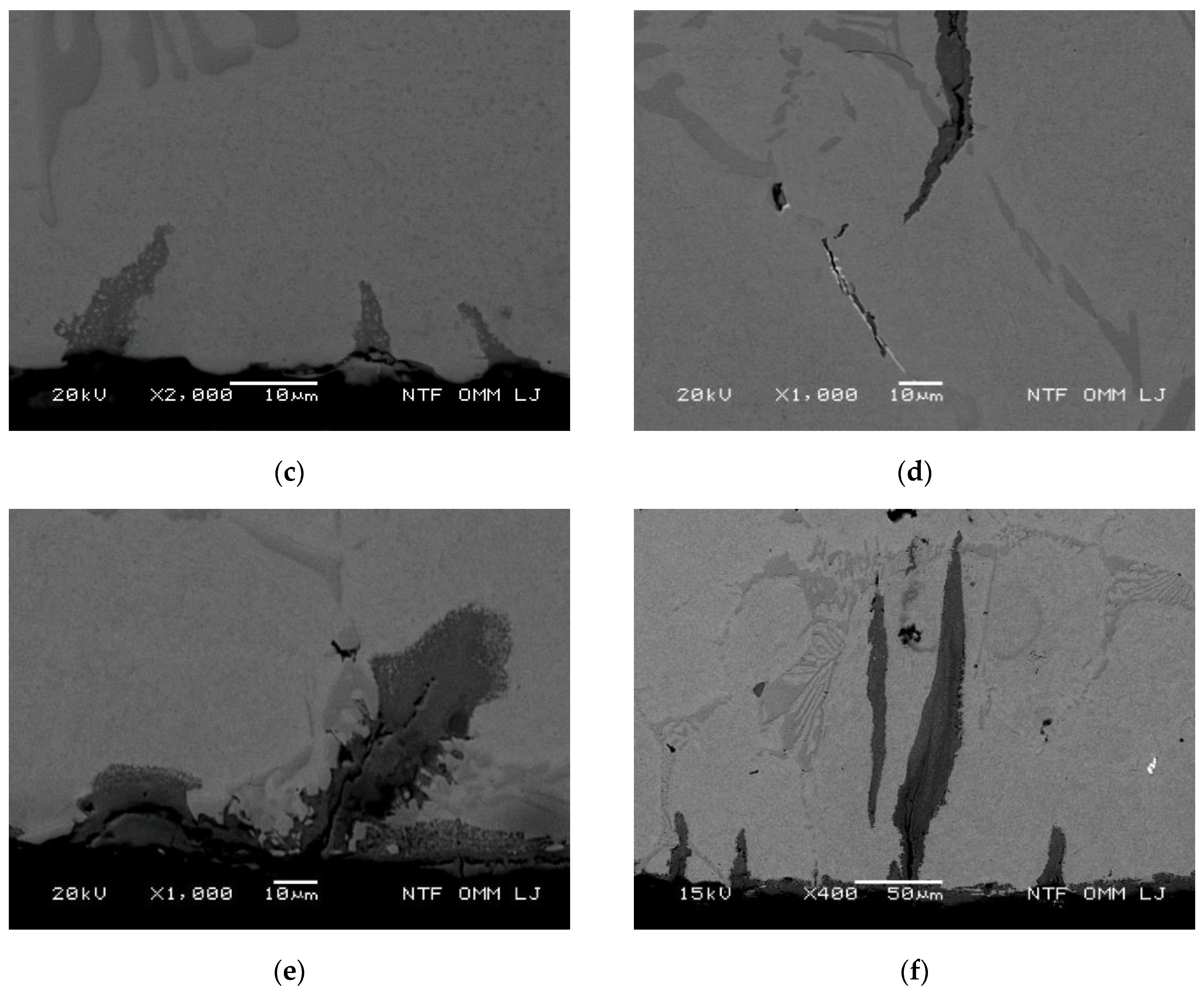
3.3.4. Oxidation Behavior and Crack Growth Direction at High Thermal Stresses

In general, crack growth at high thermal stresses (above approx. 900 MPa) can be divided into three different stages with regard to the contribution of carbide oxidation in relation to thermal stresses (cracking, crushing). In each of the three phases the contribution by oxidation is different. In stage (i), oxidation plays no significant role in crack growth, which occurs due to carbide cracking and crushing as a result of high thermal stresses (cf. Figure 5c, Figure 6a). This is especially true for the thicker carbides, which are precipitated below the surface at depths where the thermal stress is still high. Characteristic for the second stage (ii) is the lower thermal stress compared to stage (i). In this stage, crack growth is caused by carbide cracking (crushing) and by crack tip and canal oxidation.
The consequence of the oxidized material around the crack canal is an additional strain at the crack tip due to the increased volume of the oxides. In addition, the strain field around the crack canal and the crack tip oxygen diffusion to the crack tip and at the same time reduces the mechanical properties of the material around the crack tip. This results in an increased crack growth rate. The crack growth in the first and second phase mainly follows the carbide pathway. In contrast, the contribution of oxidation is relatively greater for crack growth in stage (iii) compared to the contribution of oxidation in stages (ii) and (i). The orientation of crack growth in the stage (iii) is mostly perpendicular to the cooled surface and follows the path in the matrix. However, when carbides act as obstacles at the crack tip, deviations of the crack growth direction have been observed. This was attributed to the stress field around the crack tip of the nearby internal cracks. In addition, a straight line path of crack growth in the matrix was observed when the thermal stresses acting are relatively low, i.e., thermal stresses do not cause carbide cracking in the direction perpendicular to the cooled surface. Crack nucleation and growth occurs next to the carbides also when the carbide orientation is at a low angle of inclination to the cooled surface (see Figure 8a,b). In the first stage of crack growth as a result of high thermal tensile stresses, the crushing and cracking of carbides was observed. This stress release mechanism consequently causes crack growth following carbide path, regardless of the orientation of the carbides. A higher magnification of the marked area in Figure 8a is shown in Figure 8c, where crack nucleation and carbide crushing is shown. Due to the sufficient ductility of the matrix, the cracking of carbides is caused by the strain due to thermal stress, whereby the toughness of the carbides is significantly reduced compared to the toughness of the matrix. As a result, crack growth in this mode begins independently of carbide orientation by following the carbide path. Figure 8d,e show the rapid oxidation of crack canals in cracks caused by high thermal stresses. From this it can be concluded that crack growth in the first oxidation stage follows the initial crushing and crack formation of the carbides (cf. Figure 8f). Overall it can be said that in the case of high thermal stresses, oxidation has reduced role in crack nucleation and initial growth process.
Figure 9a shows an intensive oxidation of the eutectic region. A large oxidized area at the beginning of the crack canal is visible, followed by an oxidized area of eutectic carbides. Surface bulges or elevations on the surface where the crack canal begins are also observed. In the second case, shown in Figure 9b, large oxidized eutectic regions exhibit extensive carbide cracks due to increased stresses near the crack tip. This is exhibited shown by crack branching and the occurrence of internal cracks in carbides. Therefore, oxidation of the eutectic region accelerates crack growth due to increased internal cracks formation around the crack tip as a result of increased stress on the oxidized regions.

3.3.5. Oxidation Behavior and Crack Growth Direction during Medium Thermal Stress

According to our estimation, the medium thermal stresses are in the range between 700 and 900 MPa. FEM simulations show that this is at a depth of about 10 μm at a test temperature of 500 °C. At 600 and 700 °C, medium stresses at depths between 6 and 17 μm and 14 and 25 μm are expected, respectively.
An increased crack length leads to a decrease in thermal stress and consequently to changes in crack propagation conditions. Changed crack propagation conditions are referred to here as the second stage of crack development. In this phase, a reduced thermal stress with the number of cycles is responsible for decreased crushing of the carbides. However, the thermal stresses at the crack tip are still sufficiently high, leading to the occurrence of an internal cracks near the crack tip. This leads to oxidation of the crack tip and the internal crack canals’ oxidation (cf. Figure 9). As a result of the latter, the strength of the surrounding material is reduced, which leads to accelerated crack growth. Characteristic of this stage is that the crack growth still mainly follows the carbide/matrix boundaries (see Figure 10a–d). If the crack follows the carbide/matrix boundary, it is called a carbide pathway. The oxidation of the crack tip and the crack canal in front of the crack tip contributes to the subsequent crack growth with regard to thermal stress. Figure 10a shows the entire crack with a marked area where Cr and O were mapped. The distribution of Cr is shown in Figure 10b, while the elemental map of oxygen is shown in Figure 10c. Figure 10d is a typical micrograph taken in the depth of expected medium thermal stresses. The crack follows the carbide pathway and there are slight carbide cracks. Crack nucleation and initial growth follow the carbide pathway regardless of the orientation of the primary or eutectic carbides. At this stage, a very versatile crack growth direction is characteristic, which sometimes leads to a curved crack shape.

3.3.6. Oxidation Behavior and Crack Growth Direction at Lower Thermal Stress

The third stage of crack growth was associated with an additional decrease in thermal stress. The cracking and crushing of carbides decreases as a result of the decrease in thermal stress. At this stage, oxidation behavior shows increased significance. A slight contribution of crack formation and crushing of carbides still contributes to crack growth—to a lesser extent, however, than in the first and second stage. The effective thermal stress acting in this phase is estimated to be below 700 MPa. Due to small thermal stresses, primary and secondary cracks deeper in the material were observed at depths of more than 1300 µm.
According to our estimation, the medium thermal stresses are in the range between 700 and 900 MPa. FEM simulations show that this is at a depth of about 10 μm at a test temperature of 500 °C. At 600 and 700 °C, medium stresses at depths between 6 and 17μm and 14 and 25 μm are expected, respectively.

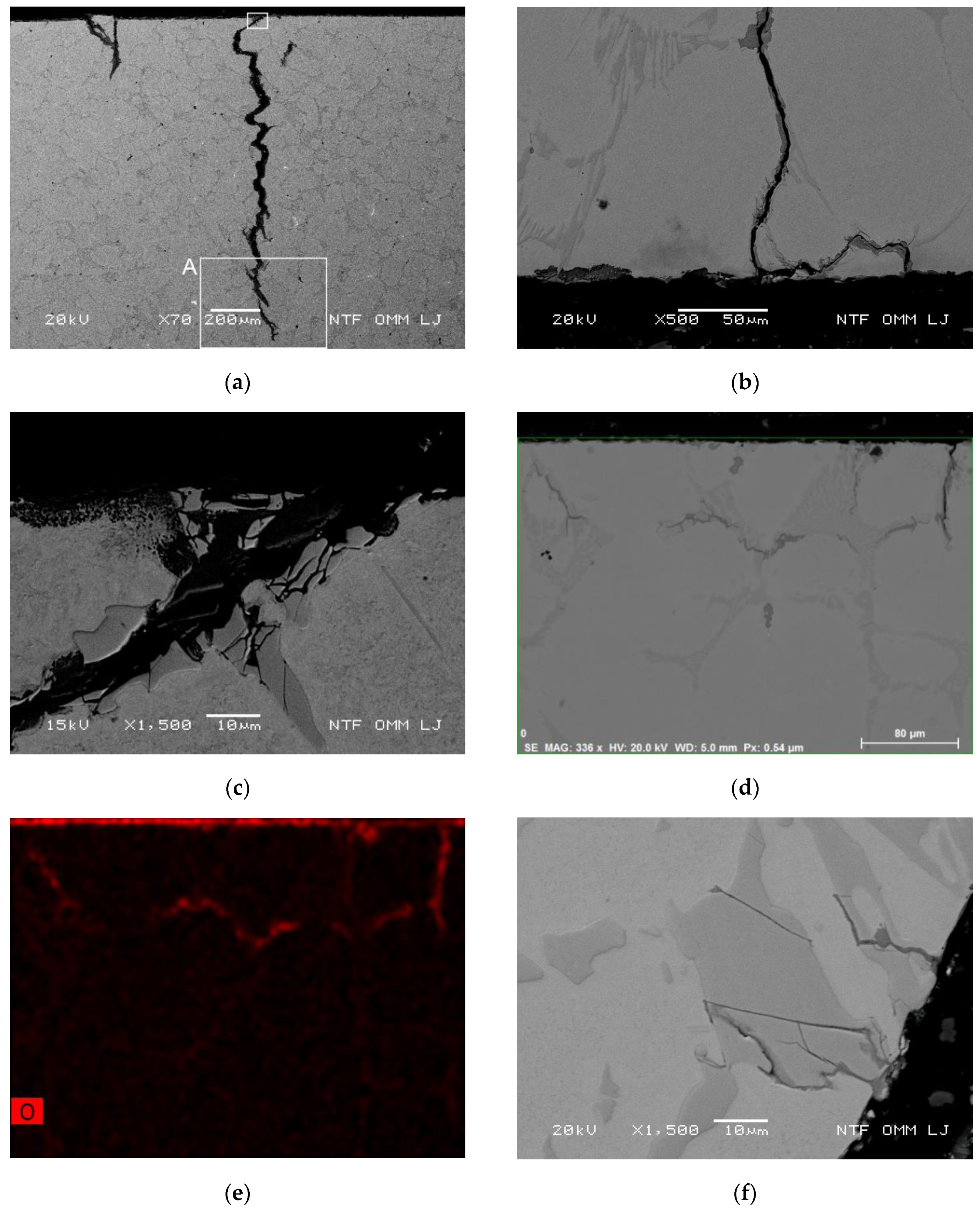
Oxidation Behavior of the Primary Crack Propagating Perpendicular to the Cooled Surface

At the test temperature of 700 °C, a thermal stress of about 410 MPa was determined at a depth of 1300 µm. Similar stresses are achieved at a test temperature of 600 °C at a depth of 1420 µm and at a depth of 1600 µm at 500 °C. Characteristic of crack growth under these conditions is that the crack propagation through the matrix is in a direction perpendicular to the cooled surface, even if the carbides are not oriented perpendicularly to the cooled surface. If the oxidation process is strong, it helps crack propagation through the matrix. In cases where no oxidation is present, the crack propagation rate decreases as the crack tip enters the matrix [6].
The strain field originating from the crack tip can still cause internal cracks, as shown in Figure 9. Internal cracks usually appear near the crack tip in the eutectic carbide region. The growth direction of the cracks through the area of the carbides with merging internal cracks does not deviate significantly from the perpendicular direction to the cooled surface. The direction of crack growth does not change the inclination (see detail A in Figure 8a and Figure 11a). Furthermore, the straightness of the crack increases in the direction of growth. In general, crack propagation follows the carbide pathway if its orientation with respect to the direction of the thermal stress does not deviate significantly from the perpendicular orientation to the cooled surface. The straight-line appearance of cracks is an important feature in the third stage of crack growth. Figure 11a shows that if the carbides are distributed in a direction perpendicular to the cooled surface, the internal cracks formed lead to the formation of a global crack. In contrast, the crack propagates through the matrix when the carbides are not oriented near the perpendicular direction to the cooled surface. The favorable oxidation direction is perpendicular to the maximum effective thermal stresses, as shown in Figure 11b (detailed view of the crack tip in the marked area), for the radial direction after 1000 thermal cycles at a test temperature of 600. Figure 11c shows two different cases (see marked areas on the left and right side) for the final stages of crack growth at depths of more than 1000 µm. It is important to note that the conditions shown apply to low thermal stress, where the importance of oxidation increases. The section in the left hand rectangle in Figure 11c shows the formation of an internal crack in front of the crack tip of the primary crack. In the next stage of crack growth, an internal crack formed in the carbide fuses before the crack tip and the crack propagates through the matrix. It can also be seen that the inner crack direction does not deviate from the vertical direction.
On the other hand, the crack shown in detail in the right rectangle in Figure 11c does not cause the formation of internal cracks in carbides due to the low thermal and crack tip stress. In this case the influence of oxidation on crack growth is increased compared to the first and second stage. It can be noted that in the case without internal carbide cracks, the crack propagation is in the oxidation favorable position in the matrix (Cr depleted areas adjacent to carbides). In contrast, in the case of high thermal stresses, internal carbide cracks precede crack growth and the direction of crack growth would follow the carbide path. Furthermore, as shown in Figure 11d in the area marked in detail, crack growth due to oxidation can occur and follow the carbide/matrix interface if no carbides are present near the crack tip and the magnitude of the applied thermal stress is sufficient. In cases wherein oxidation plays a decisive role, the crack growth direction can follow the carbide/matrix interface perpendicularly to the cooled surface and does not only propagate through the matrix. Figure 11e shows two different types of crack growth observed after 2500 cycles at 700 °C. The first type involves the formation of internal cracks in carbides and grow by oxidation in both directions; i.e., to and from the cooled surface. Characteristic of the second type of oxidation growth is the formation of two oxidation tongues at the carbide/matrix interface. In Figure 11f, oxidation was observed at the carbide/matrix interface after 2500 cycles at 500 °C. The oxidation direction at the tip of the carbide deviates and continues in the direction perpendicular to the cooled surface (i.e., perpendicular to the influence of the axial thermal stress). The occurrence of cracks at the carbide/matrix interface near the oxidation crack tip indicates a reduced adhesion between the mentioned microstructural features. Growth through the matrix in the vertical direction and growth after the carbide/matrix interface are the second and third possibilities respectively. These things happen in cases in which the crack formation of carbides does not occur near the crack tip and the angle of inclination of carbide/matrix is low enough.

Oxidation Behavior and Crack Growth Direction in the End Regions of the Secondary Cracks at 500 and 700 °C

It is characteristic of the formation of secondary cracks that their formation occurs at significantly lower thermal stresses compared to primary cracks. However, the formation of primary cracks in their final phase is also associated with lower thermal stress. From this it can be deduced that a similar role of oxidation and carbide cracking can be observed in the growth of secondary cracks as in the growth of primary cracks at a depth of more than 1300 µm. Figure 12a,b shows for the test temperature of 500 °C (Figure 12a for 1000 cycles and Figure 12b for 2500 cycles) that in the case of lower thermal stresses, cracking follows the carbide/matrix pathway and the influence of oxidation is emphasized. Cracking of carbides along the crack path is negligible and indicates a lower thermal stress and an increased importance of oxidation. From the point of view of material strength, the carbide/matrix interface is not a weak spot and crack growth through this area is strongly associated with oxidation. Moreover, in the approximately 4 μm wide band along the carbides, the Cr content is reduced and was measured with EDX in the range of 4–5 wt. %. In comparison, the Cr content in the matrix is in the range of 6–8.5 wt. %. After 2500 cycles (cf. Figure 12b) it can clearly be observed that the crack formation in carbides is low. However, the crack formation in carbides is slightly increased compared to the observation after 1000 cycles (see Figure 12a). From the observations made it can be said that both crack tip oxidation and internal oxidation of the crack canal are the driving forces of crack growth.
As expected, the observed oxidation surface is larger at the test temperature of 700 °C than at the test temperature of 500 °C. Nucleation sites for cracks are carbides of the carbide/matrix interface. For a case in which the orientation of the carbides deviates significantly from the vertical direction, the crack follows the oxidation path. This means that the crack growth is oriented in the direction of the maximum thermal stress (see Figure 12c for the condition after 1000 cycles). Figure 12d shows that after 2500 cycles crack nucleation occurred on eutectic carbides. At a depth of about 90 µm, the crack growth mode starts through the matrix and runs perpendicularly to the cooled surface. This confirms that the crack path does not always follow the carbide path or the carbide/matrix interface path.
In the case wherein the secondary crack follows the carbide path, the final phase is similar to the final phase of longer cracks (see Figure 11), since in both cases the thermal stresses are low. Reduced internal micro-crack formation occurs when the influence of thermal stress is low. In case of a small inclination angle of the carbides, this leads to changes in the crack propagation path. The crack leaves the carbide path and takes up the matrix path; i.e., the direction of growth becomes, in steps, perpendicular to the cooled surface (see Figure 12e). Similar things can be seen in Figure 12f, but in the latter case the formation of two branches in the matrix in the favorable oxidation direction is visible. The branching of the crack is perpendicular to the cooled surface, where higher thermal stresses occur.

Oxidation and Branching of Primary Cracks towards Internal Cracks

At lower thermal stress the influence of oxidation during crack growth increases. The crack growth at the test temperature of 700 °C and a depth of more than 1300 µm is shown in Figure 13a–d, whereby the influence of oxidation during crack growth is increased. In the case shown in Figure 13a (detailed view in Figure 13b), the main crack is divided into three branches. The approach of each of the three individual branches to internal cracks can be observed. This example confirms that the stress field around the internal crack tip influences the direction of oxidation; i.e., the crack growth direction is attracted to the influencing stress field. Furthermore, the case in Figure 13c shows the multiple division (oxidation) of the main crack. In general, the main oxidation path is divided into two oxidation branches, which are further individually divided into several branches. In Figure 13c the oxidation direction of the right branch (branch 1) is towards the matrix below the eutectic carbide. As already shown in this area, the Cr content is reduced, which has a direct effect on the oxidation direction. After the main oxidation tongue has completely covered this area, it begins to branch out into several tongues that approach in a vertical direction perpendicular to the cooled surface. Branch 2 is the left branch in Figure 13c and is divided into two oxidation branches. The first one grows in the opposite direction of a general crack growth (it grows towards the cooled surface), while the second (lower) branch grows in several directions away from the cooled surface. The later branch is further divided into several smaller, radially oriented branches.
At low thermal stresses, the oxidation direction is not emphasized as much as at high thermal stresses. In the latter case, an oxidation branch usually predominates. Figure 13d shows the division of the oxidation branch for the test temperature of 600 °C and 1000 cycles. The formation of oxidation in two sub-brunches occurs after the main crack has passed through the eutectic carbide. A lower Cr content in the band of about 5 μm to the carbide was identified as a major factor in the division into two branches. More detailed observations show that both branches follow the range in the matrix where a lower Cr is expected. Similarly to the previous observation, the right branch gradually, stepwise, approaches direction perpendicular to the cooled surface at a depth of about 1400 µm, with a nominal thermal stress of about 400 MPa. To describe complete oxidation, one has to consider the variation of chemical elements in the matrix near microstructural features such as carbides, since the preferred oxidation pathway may follow changes in matrix composition.

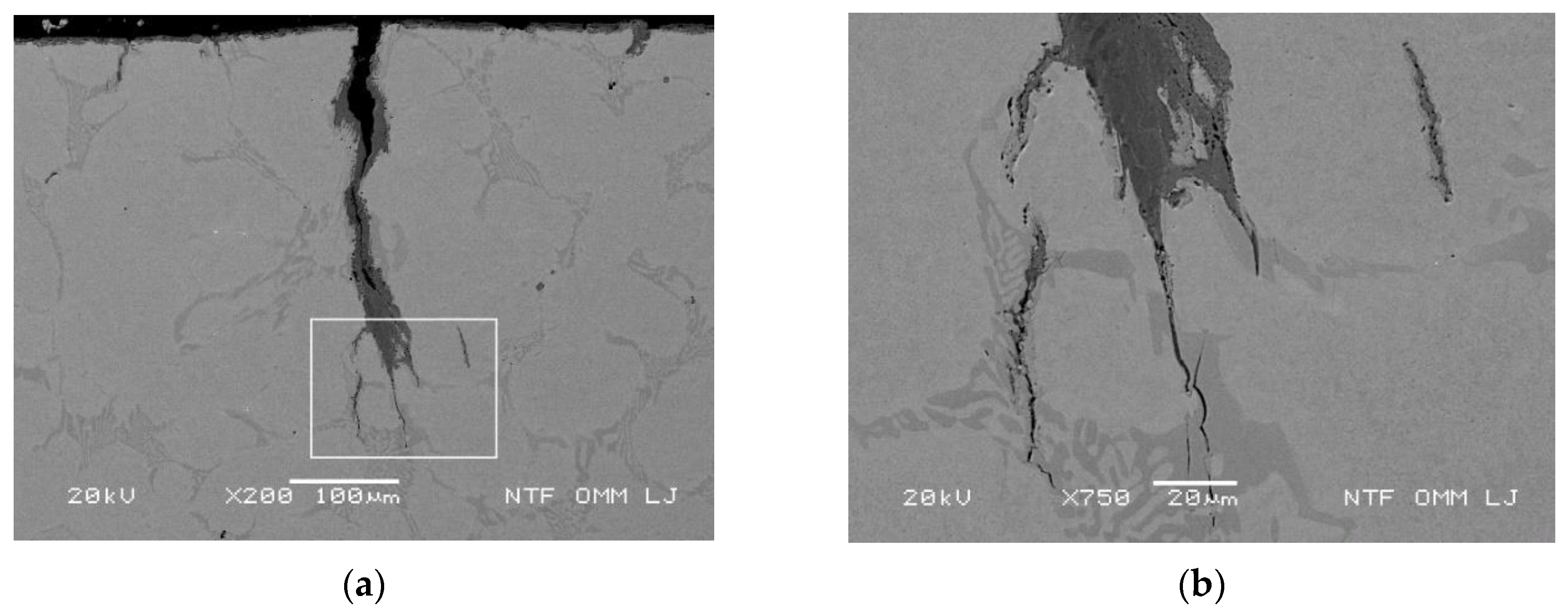
3.3.7. Conditions for an Increased Oxidation Rate of the Matrix along Carbides and Lamellae Eutectics Perpendicular to the Thermal Stresses

In previous subsections it has been shown that areas with depleted Cr content in the matrix, such as the matrix adjacent to the eutectic and along the primary carbides (see Figure 3), oxidize more rapidly than the carbides themselves (see Figure 4). The observed forms of eutectic carbides vary among lamellae, spheroids and lenticular forms. In the case of eutectic lamellae parallel to the cooled surface, oxidation of eutectic carbide is low due to the low cracking of the parallel lamellar carbides (see Figure 14a,b). A low thickness in the range of 3–6 μm leads to less cracking of the lamellae and a low subsequent oxidation of this eutectic carbide form. The oxidation behavior and crack growth are shown in Figure 10a (detailed view of an area B in Figure 14c). The oxide of the lamellae on the left side is extensive and covers a large area almost perpendicular to the cooled surface. On the other hand, the oxidation of the lamellae on the right side is oriented at an angle of approximately 45° and at the same time takes the form of a narrow tongue with a length of approximately 140 µm (cf. Figure 14c). This behavior was attributed to a reduced Cr content in the matrix near the eutectic (narrow areas between the lamellar carbides) and to the effective thermal stress applied. Similar observations were made for the eutectic lamellae shown in Figure 14d, whose inclination is about 70°, and the length of the oxidized tongue is about 120 µm.

3.3.8. Oxidation Progress of Carbides and Matrix Adjacent to Carbides

Not only does the Cr content influence the oxidation, but we also observed different oxidation progressions of the carbides depending on the Mo content. Content of Mo in primary carbides is not uniform and was determined in the range of 3–8 wt. %. Observations indicate increased oxidation when the Mo content in the carbides is lower (see Table 2 and Figure 2b). Figure 15a,b shows two cases where the oxidation front occurs in areas adjacent to and on the carbides. The carbides in Figure 15a contain a higher Mo content (5 wt. %) than the carbide shown in Figure 15b, where the measured Mo content was 2.2 wt. %. The comparison of the two oxidation fronts (test temperature of 700 °C) clearly shows that at increased Mo (Figure 15a) the oxidation of the carbides takes place in a smaller area along the carbides compared to the area with depleted Cr. Consequently, the oxidation front at these locations is the main focus of attention as far as the oxidation front on carbides is concerned. In the case shown in Figure 15b, where the Mo content in the carbides is lower, the oxidation front is aligned with the carbides and in a narrow Cr depleted band in the matrix adjacent to the carbides. The observation of differences in oxidation behavior in Figure 15a,b indicates a reduced area of the oxidized material when the Mo content is higher. This points to the dependence of the oxidation intensity of crack tips not only on the depletion of Cr, but also on the Mo content. The observation of differences in oxidation behavior in Figure 15a,b indicates a reduced area of the oxidized carbides when the Mo content is higher.

4. Discussion

The roller material is constantly exposed to heating and cooling cycles. Due to the cooling water used in rolling mills, some materials show significant surface deterioration not only due to thermal cycles but also due to oxidation. In the available scientific literature, the oxidation phenomena are mainly discussed by classical oxidation studies in humid atmospheres and under isothermal conditions [4,15,22,23,28,34,35,36,37,38]. Since thermal cycles with water cooling stress the material in each cycle, a direct comparison is very difficult. A basic oxidation degradation discussion on a similar material is given in reference [15]. In the present paper, the knowledge of oxidation of high Cr roller material is expanded from initial work on oxidation under thermal fatigue for the same material listed in reference [6]. In addition, the current paper aims to link the oxidation progress with the level of thermal stress applied.
In accordance with the literature [6,7,15,39,45], oxidation of larger eutectic carbides under the cooled surface in combination with the crack growth direction using primary carbide paths leads to fusion of the oxidized region and consequently to early spalling and chipping of the fused regions from the surface layer. A novel contribution of this work is the division of the applied thermal stress based on the stress level into stages with observed similar crack growth and oxidation degradation of the roller material. The contribution of oxidation to crack growth is conditionally divided into three different stages with respect to thermal stress and primary crack growth progress:
(i) The first stage, in which the applied thermal stresses are high, is characterized by processes of cracking and crushing of carbides related to crack growth. The crack growth follows the carbide pathway, with oxidation playing a less relevant role. However, oxidation still causes an increase in stress at the crack tips.
(ii) Second stage, in which the effective thermal stress is medium, shows crack growth by cracking and crushing of carbides and internal oxidation of cracks. Internal crack oxidation leads to increased stress at the crack tip and reduced strength of the material around the crack tip. Cracks mainly follow the carbide path.
(iii) The third stage, in which the effective thermal stresses are low, is characterized by crack growth by fusion of internal cracks and the main crack. Important is the increased role of oxidation; i.e., crack growth takes a favorable oxidation direction perpendicular to the maximum thermal stress.
Oxidation allows changes in crack growth direction; i.e., from carbide path to path through the matrix. The inclination angle to the cooled surface and the straightness of the cracks increase, and oxidation of the carbide/matrix interface is common. The oxidation growth characteristic of secondary cracks is similar to the third stage of primary crack growth.
Thermal stress; shape and size of the eutectic, contents of Cr in the matrix and eutectic carbides, orientation of the eutectic lamellae (perpendicular to the cooled surface), occurrence of cracks in eutectic carbides and temperature accelerate the oxidation of the matrix. The oxidation progress of carbides and the matrix adjacent to carbides depends on the local chemical composition. The oxidation intensity of crack tips depends not only on the depletion of Cr, but also on the Mo content. If the Mo content in the carbides is lower, the oxidation front will align along the carbides and the oxidation rate is expected to accelerate. The results obtained confirm that the matrix generally oxidizes faster. As shown in Figure 15b, carbides can oxidize at a similar rate to the matrix due to local variations in chemical composition, especially Mo content. In some cases, carbides could oxidize faster than the matrix, depending on the local chemical composition, which complements the observations of Kim et al. [34]. Large oxidation tongues in the present study contrast with oxidation studies [4,15,22,23,28,34,35,36,37,38] and tribological tests [3,9,10,11,14,16,25,26,33,35,39,40,41,42,43,44,45,46,47,48,49,50,51,52,53,54,55,56,57]. This is attributed to test conditions where thermal cycles play an important role in O diffusion and confirms the theory of Lao et al. [27] that the condition under isothermal testing in the highly plastic deformed region during sliding wear is not comparable to the behavior during hot rolling.

5. Conclusions

The oxidation behavior during crack growth was characterized on specimens after thermal fatigue tests of Cr12 (1.7C, 11.3Cr, 1.9Ni and 1.2Mo) roller steel in the temperature range of 500–700 °C. The fatigue tests were interrupted after 200, 500, 1000 and 2500 thermal cycles and examined by electron microscopy for degradation mechanisms, crack growth and oxidation behavior. Observations of the oxidation behavior are linked to the calculated magnitude of thermal stress, the properties of the matrix material and the carbides as well as the test temperature. The following conclusions can be drawn from the results obtained:
  • The orientation of the carbides embedded in the microstructure is varied, which in combination with the oxidation behavior and the thermal stress influence crack growth.
  • Thermal stress depends on the test temperature and the distance from the cooled surface. The FEM simulations were used to determine the change in thermal stress acting through the sample wall and show a strong correlation between temperature and stress value. An effective thermal stress of more than 900 MPa was estimated to be high. The low effective thermal stress is below 700 MPa. Values between low and high were assumed as medium thermal stress.
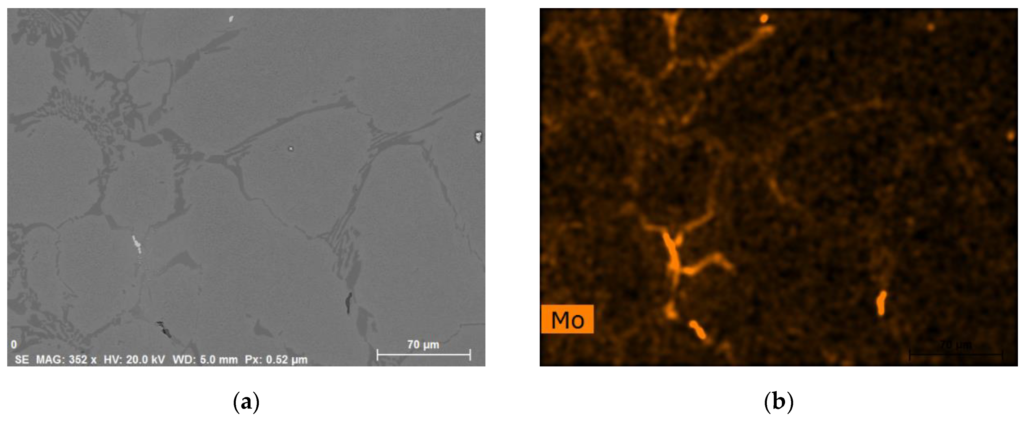
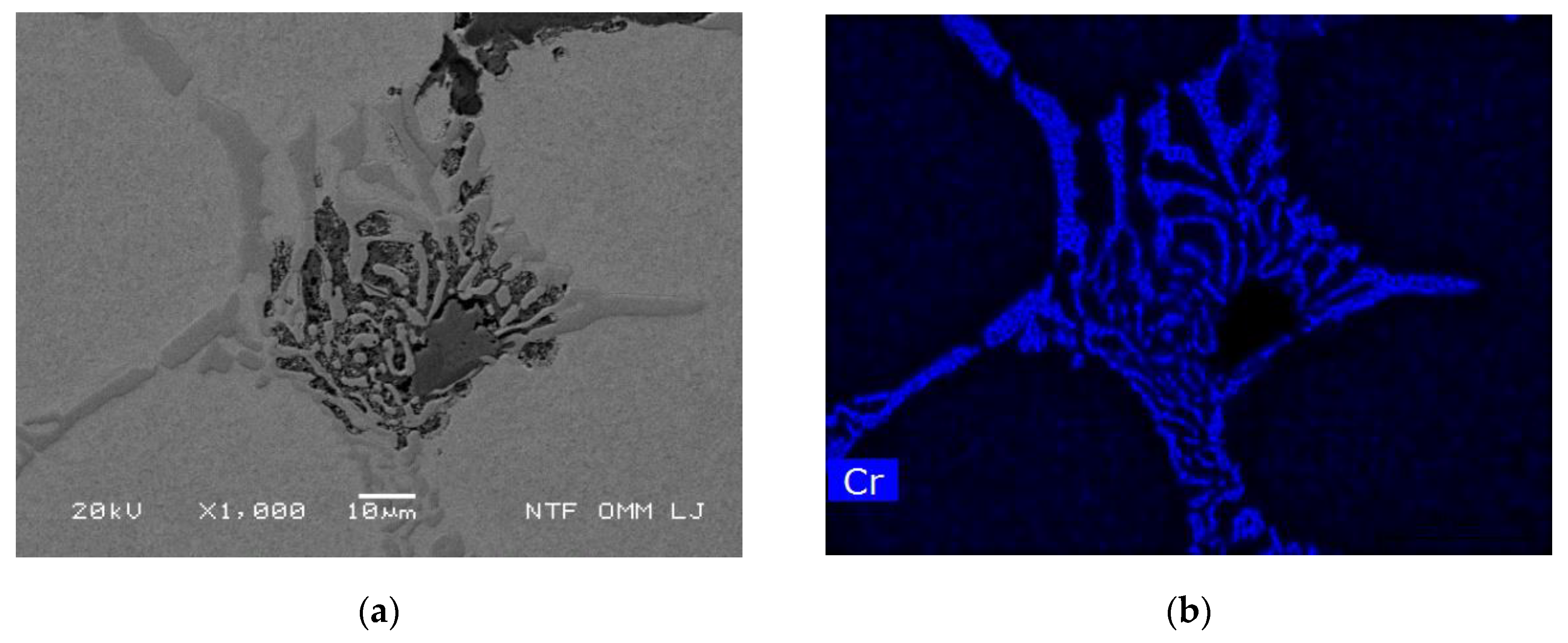
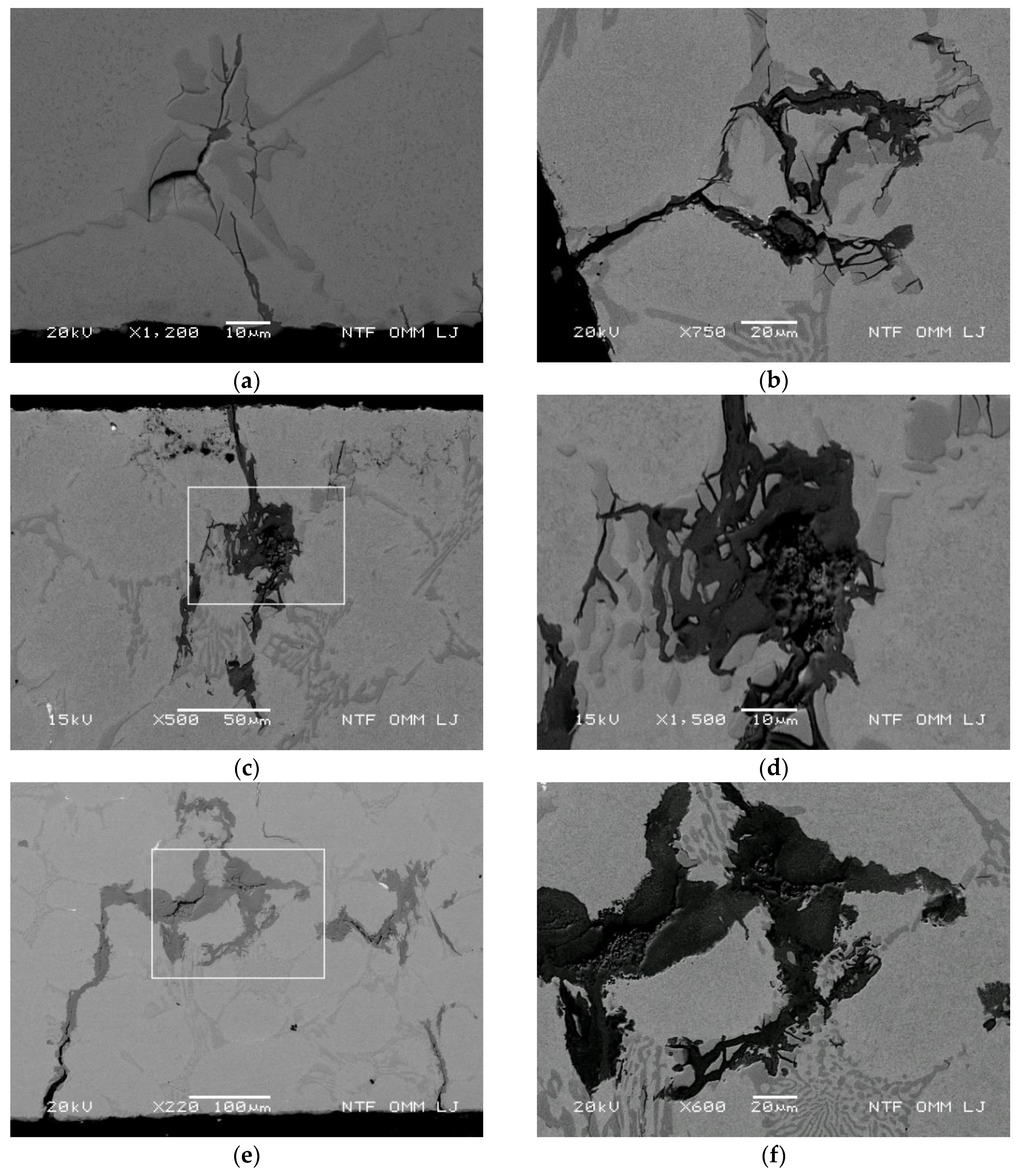
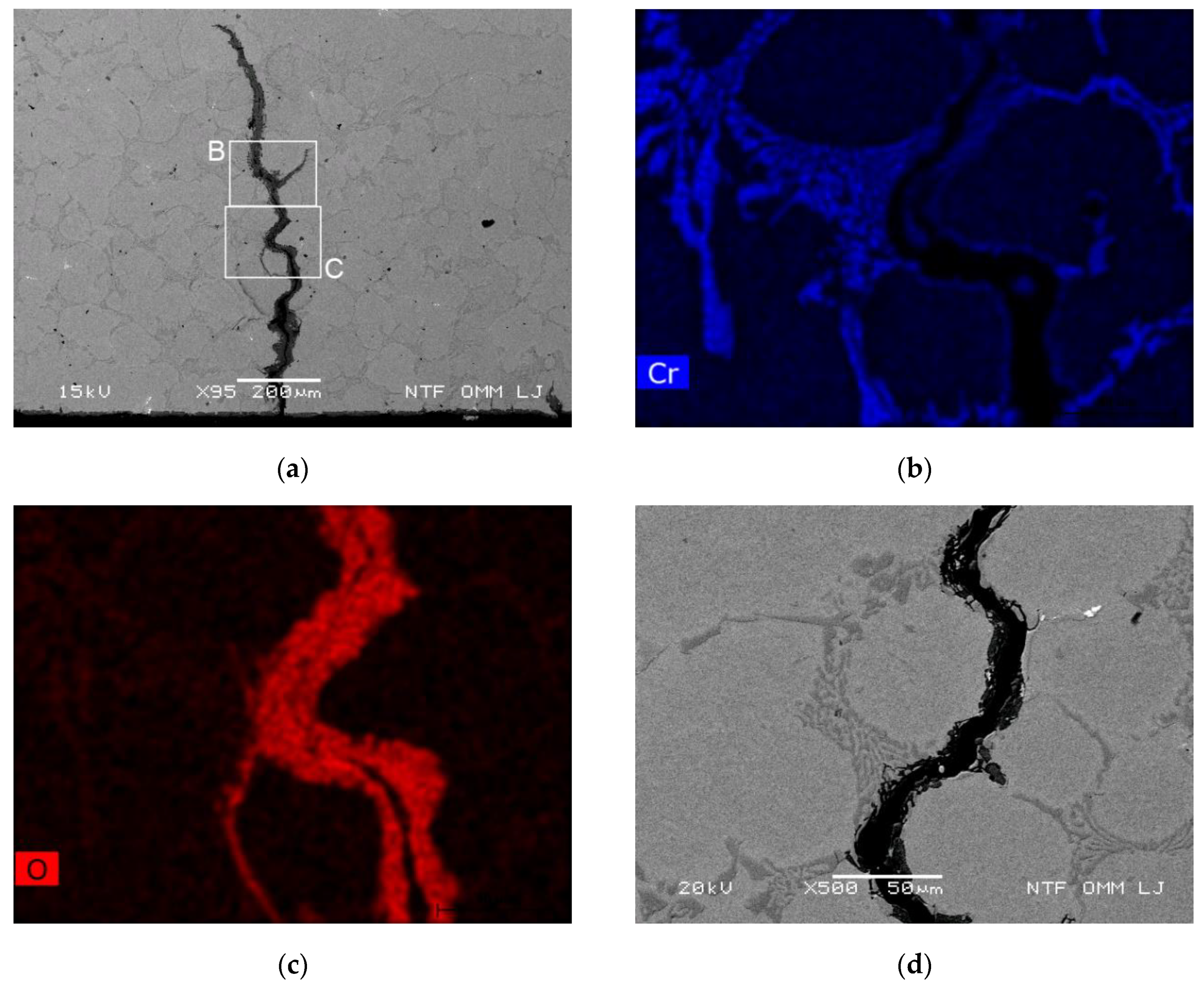
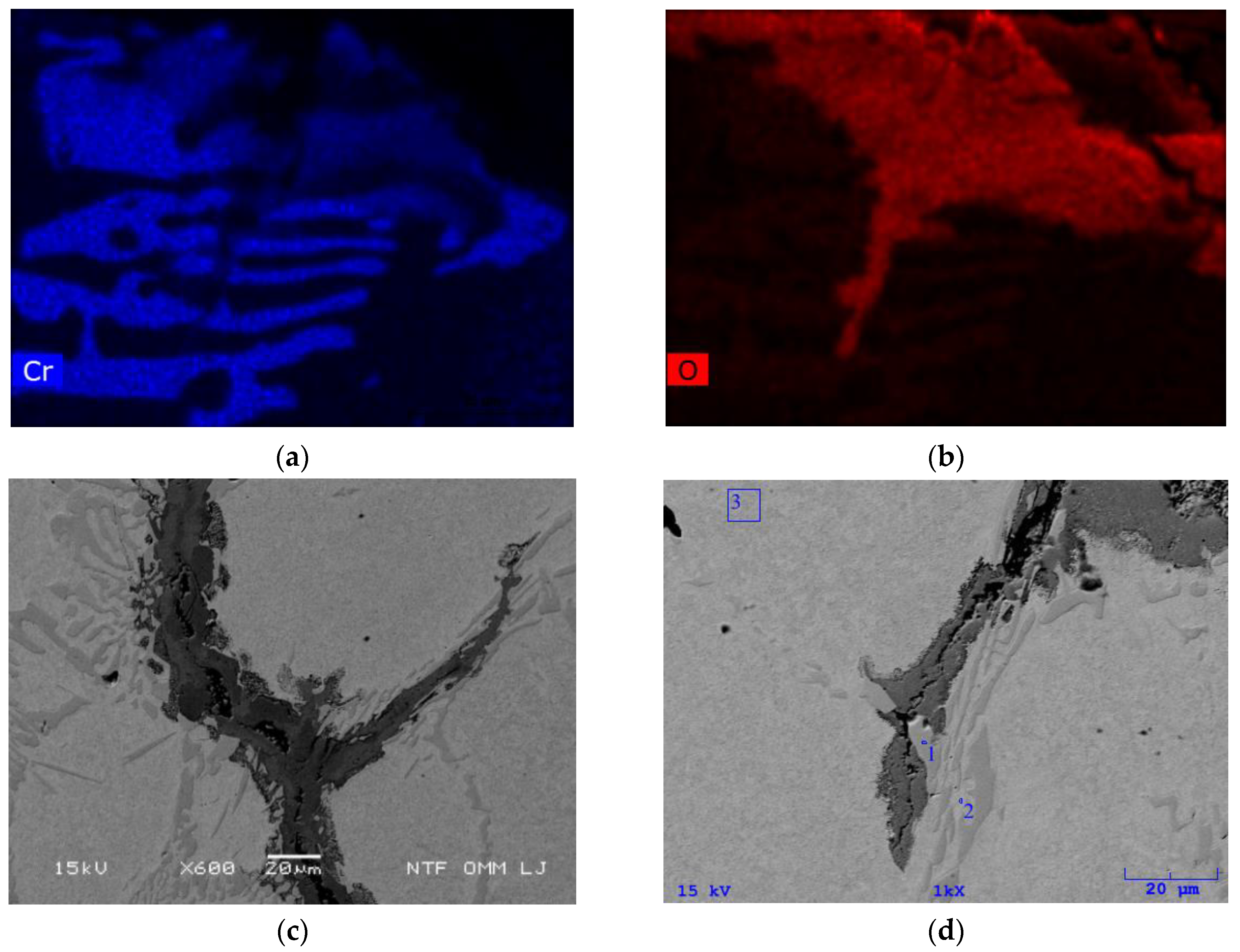
  • Areas with depleted Cr content in the vicinity of eutectic carbides and within a narrow band adjacent to the primary carbides were observed. Areas with reduced Cr are more susceptible to oxidation. This applies to material surrounding eutectic carbide and band adjacent the primary carbides.
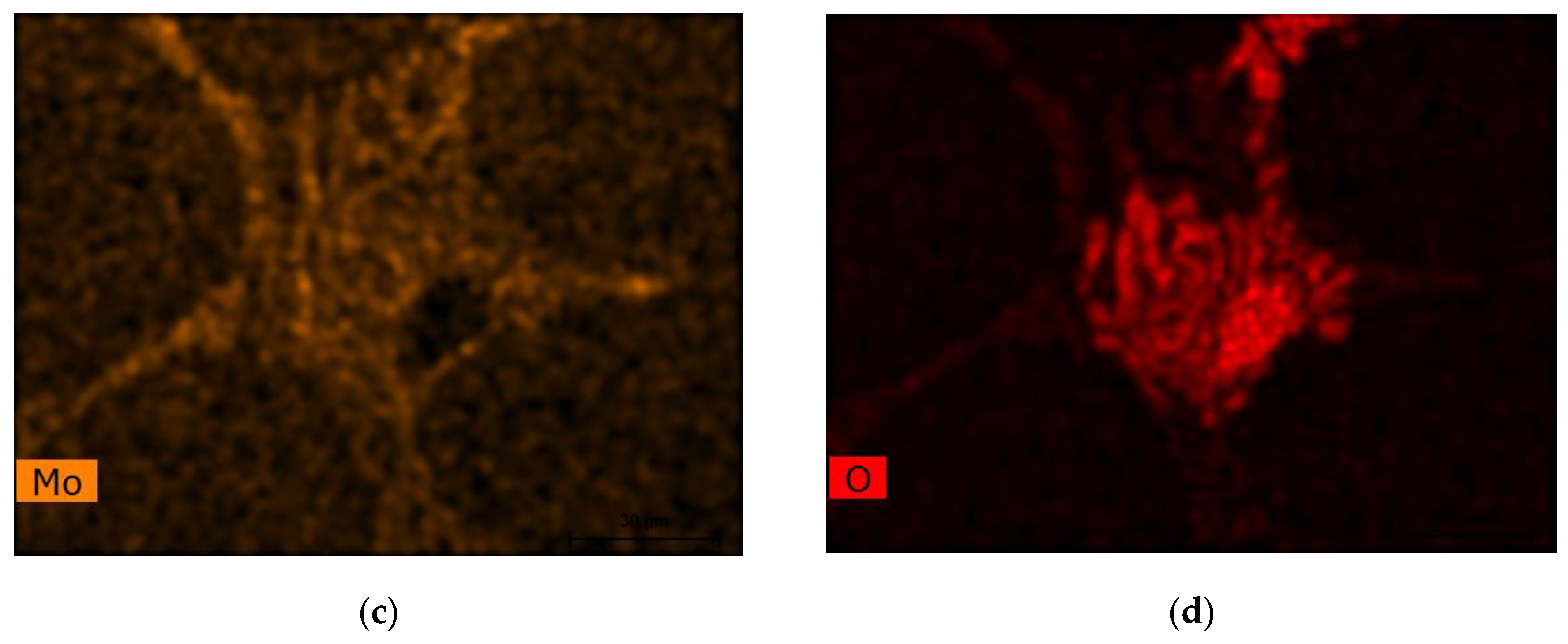
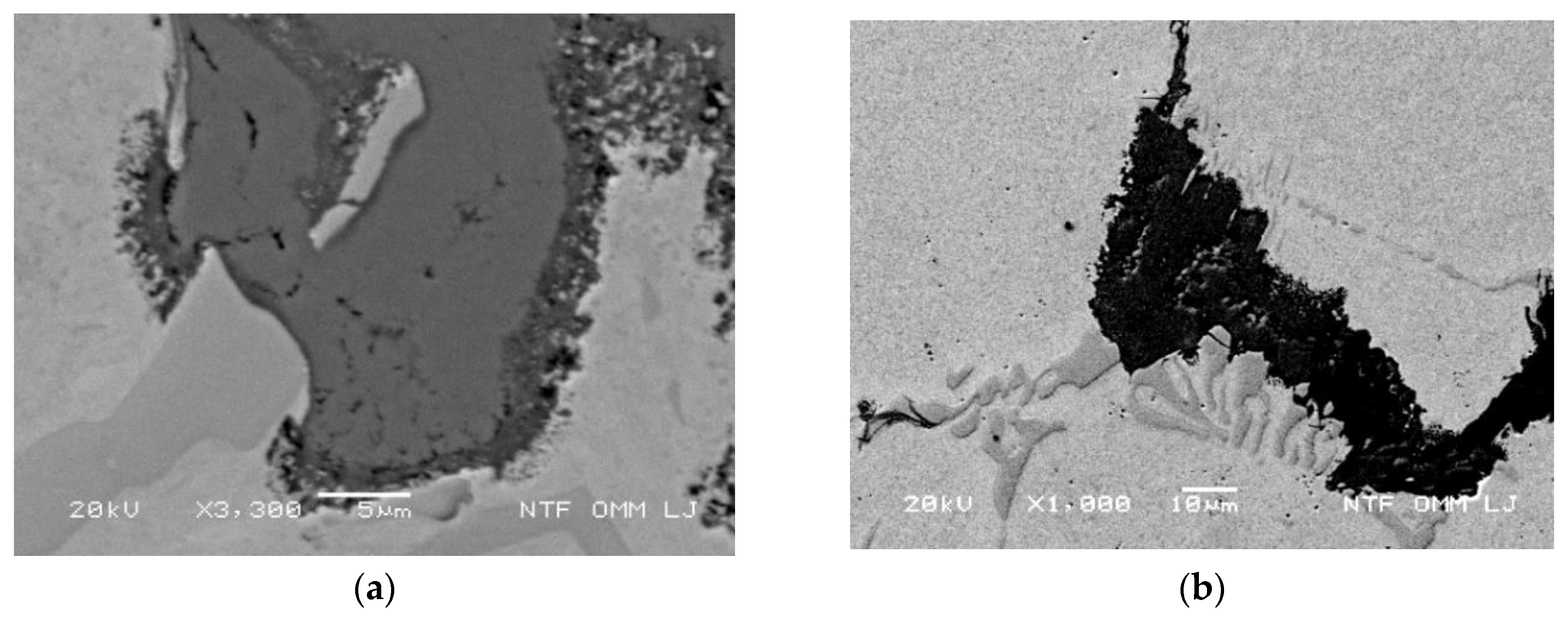
  • The oxidation behavior is temperature dependent and influences thermal stress as well as carbide and matrix properties. The oxide area grows with higher temperature and thermal stress. The oxidation mechanism is based on diffusion growth, and the oxidation rate of the matrix adjacent to the carbides is generally higher than in the oxidation of carbides. Due to the variation of the local chemical composition, carbides could oxidize faster in special cases.
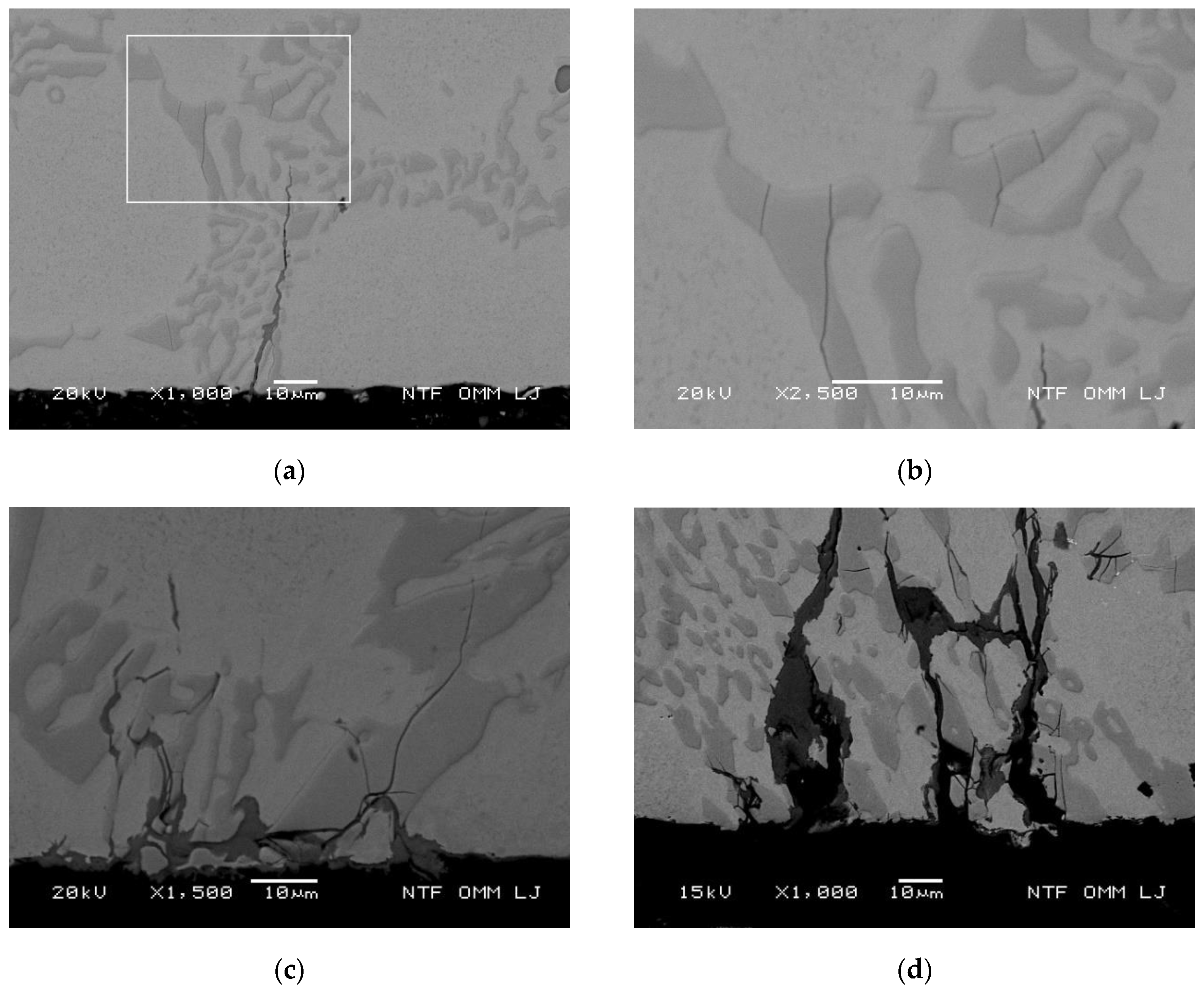
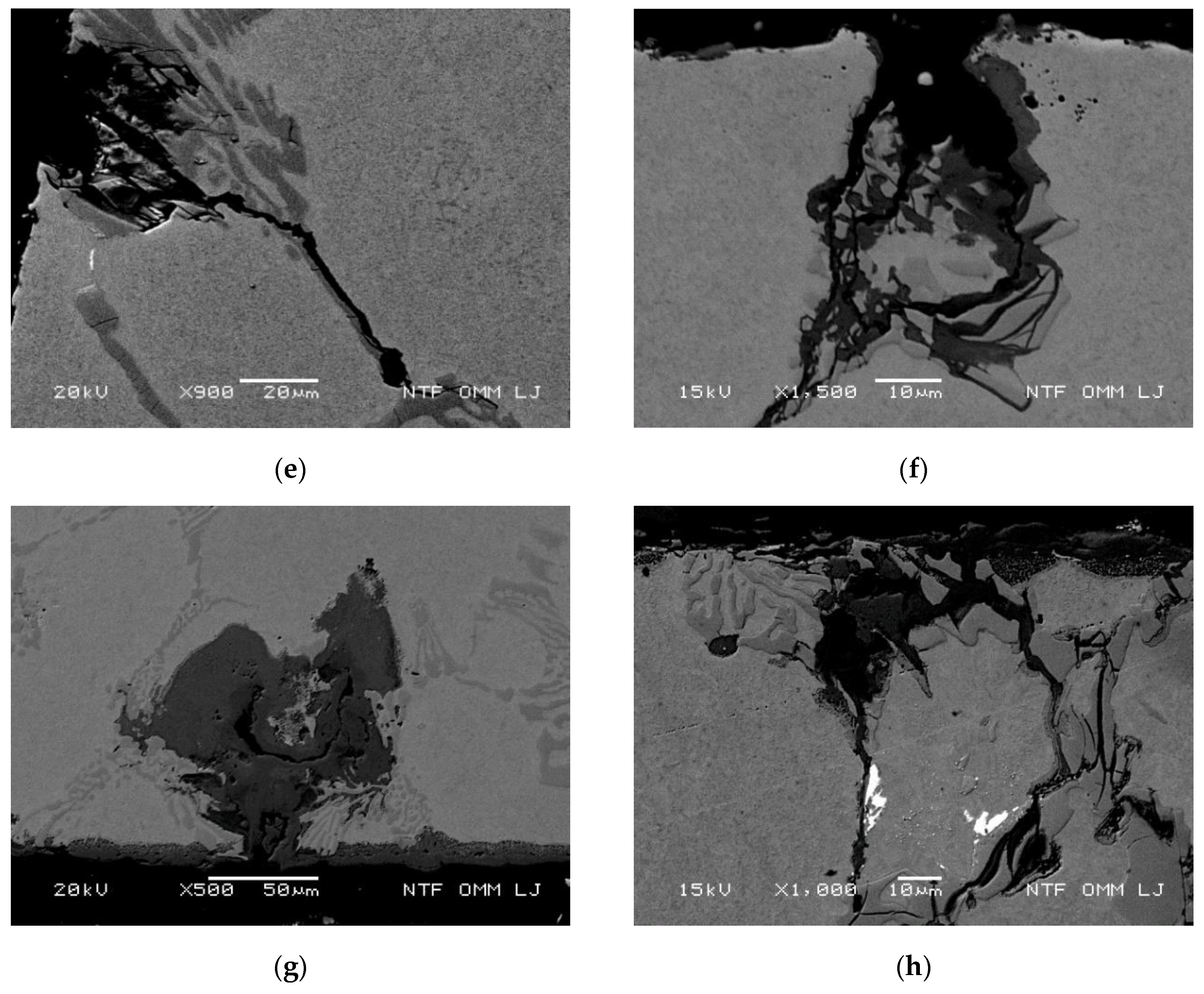
  • The direction of oxidation in the matrix is determined by the direction of the effective thermal stress in combination with the crack tip stress. The oxidation of the eutectic carbides located below the surface is associated with the cracking of eutectic carbides and the formation of cracks from the surface to eutectic carbides, which enabled the diffusion of oxygen in the crack canal.
  • Cracking of eutectic carbides is accelerated by thermal stresses, which accelerate the oxidation rates of carbides. The influence of the Mo content on the oxidation of carbides and consequently on crack growth was observed. An increased content of Mo in carbides slows down oxidation around the carbides.

Author Contributions

Conceptualization, D.B. and M.T.; formal analysis, D.B.; investigation, D.B., M.G. and M.T.; resources, G.K.; supervision, G.K.; validation, G.K. and M.T.; visualization, D.B.; writing—original draft, D.B.; writing—review and editing, D.B., M.G. and M.T. All authors have read and agreed to the published version of the manuscript.

Funding

We are grateful to the Slovenian Research Agency (ARRS) for funding under program grants P2-0344 and P2-0268.

Acknowledgments

The authors would like to thank Peter Fajfar and Matej Drobne for the many useful discussions and Valji d.o.o. (Štore, Slovenija) for providing the material used in this study. The research assistance of Andrej Penko and Samo Smolej is gratefully appreciated.

Conflicts of Interest

The authors declare no conflict of interest. The funders had no role in the design of the study; in the collection, analyses, or interpretation of data; in the writing of the manuscript, or in the decision to publish the results.

References

  1. Spuzic, S.; Strafford, K.N.; Subramanian, C.; Savage, G. Wear of hot rolling mill rolls: An overview. Wear 1994, 176, 261–271. [Google Scholar] [CrossRef]
  2. Bataille, C.; Luc, E.; Bigerelle, M.; Deltombe, R.; Dubar, M. Rolls wear characterization in hot rolling process. Tribol. Int. 2016, 100, 328–337. [Google Scholar] [CrossRef]
  3. Hanlon, D.N.; Rainforth, W.M. The rolling sliding wear response of conventionally processed and spray formed high speed steel at ambient and elevated temperature. Wear 2003, 255, 956–966. [Google Scholar] [CrossRef]
  4. Zamri, W.F.H.; Kosasih, P.B.; Tieu, A.K.; Zhu, Q.; Zhu, H. Variations in the microstructure and mechanical properties of the oxide layer on high speed steel hot rolling work rolls. J. Mater. Process. Technol. 2012, 212, 2597–2608. [Google Scholar] [CrossRef]
  5. Bombač, D.; Kugler, G.; Markoli, B.; Terčelj, M. Hot work roller surface layer degradation progress during thermal fatigue in the temperature range 500–700 °C. Int. J. Fatigue 2017, 104, 355–365. [Google Scholar] [CrossRef]
  6. Bombač, D.; Gintalas, M.; Kugler, G.; Terčelj, M. Thermal fatigue behaviour of Fe-1.7C-11.3Cr-1.9Ni-1.2Mo roller steel in temperature range 500–700 °C. Int. J. Fatigue 2019, 121, 98–111. [Google Scholar] [CrossRef]
  7. Colás, R.; Ramírez, J.; Sandoval, I.; Morales, J.C.; Leduc, L.A. Damage in hot rolling work rolls. Wear 1999, 230, 56–60. [Google Scholar] [CrossRef]
  8. Tieu, A.K.; Zhu, Q.; Zhu, H.; Lu, C. An investigation into the tribological behaviour of a work roll material at high temperature. Wear 2011, 273, 43–48. [Google Scholar] [CrossRef]
  9. Choi, J.-W.; Kim, D. Mechanisms of Surface Deterioration of High-Ni Grain Roll for Hot Strip Rolling. ISIJ Int. 1999, 39, 823–828. [Google Scholar] [CrossRef]
  10. Lee, J.H.; Oh, J.C.; Park, J.W.; Lee, H.C.; Lee, S. Effects of Tempering Temperature on Wear Resistance and Surface Roughness of a High Speed Steel Roll. ISIJ Int. 2001, 41, 859–865. [Google Scholar] [CrossRef]
  11. Kato, O.; Yamamoto, H.; Ataka, M.; Nakajima, K. Mechanisms of Surface Deterioration of Roll for Hot Strip Rolling. ISIJ Int. 1992, 32, 1216–1220. [Google Scholar] [CrossRef] [Green Version]
  12. Deng, G.Y.; Zhu, H.T.; Tieu, A.K.; Su, L.H.; Reid, M.; Zhang, L.; Wei, P.T.; Zhao, X.; Wang, H.; Zhang, J.; et al. Theoretical and experimental investigation of thermal and oxidation behaviours of a high speed steel work roll during hot rolling. Int. J. Mech. Sci. 2017, 131–132, 811–826. [Google Scholar] [CrossRef] [Green Version]
  13. Deng, G.Y.; Zhu, Q.; Tieu, K.; Zhu, H.T.; Reid, M.; Saleh, A.A.; Su, L.H.; Ta, T.D.; Zhang, J.; Lu, C.; et al. Evolution of microstructure, temperature and stress in a high speed steel work roll during hot rolling: Experiment and modelling. J. Mater. Process. Technol. 2017, 240, 200–208. [Google Scholar] [CrossRef]
  14. Delaunois, F.; Stanciu, V.I.; Sinnaeve, M. Resistance to High-Temperature Oxidation and Wear of Various Ferrous Alloys Used in Rolling Mills. Metall. Mater. Trans. A 2018, 49, 822–835. [Google Scholar] [CrossRef]
  15. Molinari, A.; Straffelini, G.; Tomasi, A.; Biggi, A.; Corbo, G. Oxidation behaviour of ledeburitic steels for hot rolls. Mater. Sci. Eng., A 2000, 280, 255–262. [Google Scholar] [CrossRef]
  16. Joos, O.; Boher, C.; Vergne, C.; Gaspard, C.; Nylen, T.; Rezaï-Aria, F. Assessment of oxide scales influence on wear damage of HSM work rolls. Wear 2007, 263, 198–206. [Google Scholar] [CrossRef] [Green Version]
  17. Yang, W.; Huang, Y.; Zhou, Q.; Wang, J.; Jin, X.; Keer, L.M. Parametric study on stressed volume and its application to the quantification of rolling contact fatigue performance of heterogeneous material. Tribol. Int. 2017, 107, 221–232. [Google Scholar] [CrossRef] [Green Version]
  18. Hamraoui, M. Thermal behaviour of rollers during the rolling process. Appl. Therm. Eng. 2009, 29, 2386–2390. [Google Scholar] [CrossRef]
  19. Mercado-Solis, R.D.; Beynon, J.H. Simulation of thermal fatigue in hot strip mill work rolls. Scand. J. Metall. 2005, 34, 175–191. [Google Scholar] [CrossRef]
  20. Belzunce, F.J.; Ziadi, A.; Rodriguez, C. Structural integrity of hot strip mill rolling rolls. Eng. Fail. Anal. 2004, 11, 789–797. [Google Scholar] [CrossRef]
  21. Günen, A.; Kanca, E.; Karakaş, M.S.; Koç, V.; Gök, M.S.; Kanca, Y.; Çürük, A.; Demir, M. High temperature wear behavior of the surface-modified externally cooled rolls. Surf. Coat. Technol. 2018, 348, 130–141. [Google Scholar] [CrossRef]
  22. Zhu, Q.; Zhu, H.T.; Tieu, A.K.; Reid, M.; Zhang, L.C. In-situ investigation of oxidation behaviour in high-speed steel roll material under dry and humid atmospheres. Corros. Sci. 2010, 52, 2707–2715. [Google Scholar] [CrossRef]
  23. Ramírez-Ramírez, J.H.; Colás, R.; Garza-Montes-de-Oca, N.F. High Temperature Oxidation of a Work Roll Grade High-Chromium White Cast Iron. J. Iron. Steel Res. Int. 2013, 20, 122–129. [Google Scholar] [CrossRef]
  24. Garza-Montes-de-Oca, N.F.; Colás, R.; Rainforth, W.M. On the damage of a work roll grade high speed steel by thermal cycling. Eng. Fail. Anal. 2011, 18, 1576–1583. [Google Scholar] [CrossRef]
  25. Kang, Y.J.; Oh, J.C.; Lee, H.C.; Lee, S. Effects of carbon and chromium additions on the wear resistance and surface roughness of cast high-speed steel rolls. Metall. Mater. Trans. A 2001, 32, 2515–2525. [Google Scholar] [CrossRef] [Green Version]
  26. Pellizzari, M.; Molinari, A.; Straffelini, G. Tribological behaviour of hot rolling rolls. Wear 2005, 259, 1281–1289. [Google Scholar] [CrossRef]
  27. Lao, Y.; Du, H.; Xiong, T.; Wang, Y. Evolution Behaviors of Oxides in Severely Plastic Deformed Region of AISI 52100 Steel during Dry Sliding Wear. J. Mater. Sci. Technol. 2017, 33, 330–337. [Google Scholar] [CrossRef]
  28. Cho, S.; Jo, I.; Kim, H.; Kwon, H.-T.; Lee, S.-K.; Lee, S.-B. Effect of TiC addition on surface oxidation behavior of SKD11 tool steel composites. Appl. Surf. Sci. 2017, 415, 155–160. [Google Scholar] [CrossRef]
  29. Min, Y.; Jens, B.; Wu, X.; Xu, L. Oxidation and Thermal Fatigue Behaviors of Two Type Hot Work Steels during Thermal Cycling. J. Iron. Steel Res. Int. 2013, 20, 90–97. [Google Scholar] [CrossRef]
  30. Molinari, A.; Pellizzari, M.; Tremea, A.; Biggi, A.; Corbo, G. Effect of matrix microhardness on thermal fatigue behaviour of spincast high speed steels for hot rolls. Mater. Sci. Technol. 2005, 21, 352–356. [Google Scholar] [CrossRef]
  31. Molinari, A.; Tremea, A.; Pellizzari, M.; Biggi, A.; Corbo, G. High speed steels for hot rolls with improved impact and thermal fatigue resistance. Mater. Sci. Technol. 2002, 18, 1574–1580. [Google Scholar] [CrossRef]
  32. Pellizzari, M.; Cescato, D.; Flora, M.G. De Hot friction and wear behaviour of high speed steel and high chromium iron for rolls. Wear 2009, 267, 467–475. [Google Scholar] [CrossRef]
  33. Oksanen, V.; Valtonen, K.; Andersson, P.; Vaajoki, A.; Laukkanen, A.; Holmberg, K.; Kuokkala, V.T. Comparison of laboratory rolling–sliding wear tests with in-service wear of nodular cast iron rollers against wire ropes. Wear 2015, 340–341, 73–81. [Google Scholar] [CrossRef]
  34. Kim, H.-H.; Lim, J.-W.; Lee, J.-J. Oxidation Behavior of High-speed Steels in Dry and Wet Atmospheres. ISIJ Int. 2003, 43, 1983–1988. [Google Scholar] [CrossRef]
  35. Pellizzari, M.; Molinari, A.; Cescato, D.; Tremea, A.; Corbo, G.; Biggi, A. Wear and friction behaviour of high chromium iron and high speed steels for hot rolls. In Proceedings of the International Conference on Abrasion 2005, Sao Paulo, Brazil, 14–17 August 2005; Volume 2005, pp. 189–198. [Google Scholar]
  36. Monteiro, M.J.; Saunders, S.R.J.; Rizzo, F.C. The Effect of Water Vapour on the Oxidation of High Speed Steel, Kinetics and Scale Adhesion. Oxid. Met. 2011, 75, 57–76. [Google Scholar] [CrossRef]
  37. Garza-Montes-de-Oca, N.F.; Colás, R.; Rainforth, W.M. High Temperature Oxidation of a Work Roll Grade High Speed Steel. Oxid. Met. 2011, 76, 451. [Google Scholar] [CrossRef]
  38. Molinari, A.; Pellizzari, M.; Biggi, A.; Corbo, G.; Tremea, A. Primary carbides in spincast HSS for hot rolls and their effect on the oxidation behaviour. In Proceedings of the Proceedings 6th International Tooling Conference, Karlstadt, Germany, 10–13 September 2002; pp. 365–377. [Google Scholar]
  39. Garza-Montes-de-Oca, N.F.; Rainforth, W.M. Wear mechanisms experienced by a work roll grade high speed steel under different environmental conditions. Wear 2009, 267, 441–448. [Google Scholar] [CrossRef]
  40. Li, C.; Liu, X.; Wang, G. New Method for Evaluating Thermal Wear of Rolls in Rolling Process. J. Iron. Steel Res. Int. 2008, 15, 52–55. [Google Scholar] [CrossRef]
  41. Pellizzari, M.; Flora, M.G. De Influence of laser hardening on the tribological properties of forged steel for hot rolls. Wear 2011, 271, 2402–2411. [Google Scholar] [CrossRef]
  42. Sano, Y.; Hattori, T.; Haga, M. Characteristics of High-carbon High Speed Steel Rolls for Hot Strip Mill. ISIJ Int. 1992, 32, 1194–1201. [Google Scholar] [CrossRef]
  43. Park, J.W.; Lee, H.C.; Lee, S. Composition, microstructure, hardness, and wear properties of high-speed steel rolls. Metall. Mater. Trans. A 1999, 30, 399–409. [Google Scholar] [CrossRef] [Green Version]
  44. Lundberg, S.-E.; Gustafsson, T. The influence of rolling temperature on roll wear, investigated in a new high temperature test rig. J. Mater. Process. Technol. 1994, 42, 239–291. [Google Scholar] [CrossRef]
  45. Hanlon, D.N.; Rainforth, W.M.; Sellars, C.M. The rolling/sliding wear response of conventionally processed and spray formed high chromium content cast iron at ambient and elevated temperature. Wear 1999, 225–229, 587–599. [Google Scholar] [CrossRef]
  46. Xu, L.; Fan, X.; Wei, S.; Liu, D.; Zhou, H.; Zhang, G.; Zhou, Y. Microstructure and wear properties of high-speed steel with high molybdenum content under rolling-sliding wear. Tribol. Int. 2017, 116, 39–46. [Google Scholar] [CrossRef]
  47. Xu, L.; Xing, J.; Wei, S.; Zhang, Y.; Long, R. Investigation on wear behaviors of high-vanadium high-speed steel compared with high-chromium cast iron under rolling contact condition. Mater. Sci. Eng. A 2006, 434, 63–70. [Google Scholar] [CrossRef]
  48. Kang, M.; Suh, Y.; Oh, Y.-J.; Lee, Y.-K. The effects of vanadium on the microstructure and wear resistance of centrifugally cast Ni-hard rolls. J. Alloys Compd. 2014, 609, 25–32. [Google Scholar] [CrossRef]
  49. Mercado-Solis, R.D.; Talamantes-Silva, J.; Beynon, J.H.; Hernandez-Rodriguez, M.A.L. Modelling surface thermal damage to hot mill rolls. Wear 2007, 263, 1560–1567. [Google Scholar] [CrossRef]
  50. Xu, L.; Wei, S.; Xing, J.; Long, R. Effects of carbon content and sliding ratio on wear behavior of high-vanadium high-speed steel (HVHSS) under high-stress rolling–sliding contact. Tribol. Int. 2014, 70, 34–41. [Google Scholar] [CrossRef]
  51. Vergne, C.; Boher, C.; Gras, R.; Levaillant, C. Influence of oxides on friction in hot rolling: Experimental investigations and tribological modelling. Wear 2006, 260, 957–975. [Google Scholar] [CrossRef] [Green Version]
  52. Hokkirigawa, K.; Kato, T.; Fukuda, T.; Shinooka, M. Analysis of Sliding Wear Mechanism of Oxide Films on Hot Roll Surfaces Based On In-Situ Observation of Wear Process by the CCD Microscope Tribosystem. J. Jpn. Soc. Tribol. 1997, 42, 777–784. [Google Scholar]
  53. Zhu, H.; Zhu, Q.; Tieu, A.K.; Kosasih, B.; Kong, C. A simulation of wear behaviour of high-speed steel hot rolls by means of high temperature pin-on-disc tests. Wear 2013, 302, 1310–1318. [Google Scholar] [CrossRef]
  54. Ren, X.; Fu, H.; Xing, J.; Yi, Y. Research on high-temperature dry sliding friction wear behavior of CaTi modified high boron high speed steel. Tribol. Int. 2019, 132, 165–176. [Google Scholar] [CrossRef]
  55. Hao, L.; Wu, H.; Wei, D.; Cheng, X.; Zhao, J.; Luo, S.; Jiang, L.; Jiang, Z. Wear and friction behaviour of high-speed steel and indefinite chill material for rolling ferritic stainless steels. Wear 2017, 376–377, 1580–1585. [Google Scholar] [CrossRef] [Green Version]
  56. Torres, H.; Varga, M.; Widder, F.; Cihak-Bayr, U.; Viskovic, O.; Ripoll, M.R. Experimental simulation of high temperature sliding contact of hot rolled steel. Tribol. Int. 2016, 93, 745–754. [Google Scholar] [CrossRef]
  57. Savage, G.; Boelen, R.; Horti, A.; Morikawa, H.; Tsujimoto, Y. Hot wear testing of roll alloys. In Proceedings of the Mechanical Working and Steel Processing Conference Proceedings, Cleveland, OH, USA, 13–16 October 1996; pp. 333–340. [Google Scholar]
Figure 1. (a) Meshed finite element model of the sample, and (b) stress distribution through the sample wall at 700 °C (solid line), 600 °C (dashed line) and 500 °C (dashed dotted line).
Metals 10 00450 g001aMetals 10 00450 g001b
Figure 2. Initial Cr12 roller steel microstructure: (a) backscatter secondary electron (BSE) micrograph; (b) elemental distribution of Mo.
Metals 10 00450 g002
Figure 3. BSE micrograph and elemental line distributions of Cr, Mo, V, Ni and Fe in matrix and carbides: (a) primary carbides, (b) line distribution of elements across primary carbides, (c) eutectic carbides and (d) line distribution of elements across eutectic carbides.
Metals 10 00450 g003
Figure 4. Oxidized inter eutectic matrix area after 2500 cycles at 700 °C: (a) BSE micrograph; and elemental distributions of (b) Cr, (c) Mo and (d) O.
Metals 10 00450 g004aMetals 10 00450 g004b
Figure 5. Oxidation behavior at the cooled surface and cracked eutectic carbides: (a) initial eutectic cracking after 1000 cycles at 500 °C, and (b) higher magnification of the window in subfigure a. Initial oxidation around the cracked eutectic carbide at 600 °C: (c) after 1000 cycles and (d) after 2500 cycles. Observed oxidation around the eutectic carbides after 2500 cycles: (e) at 500 °C, (f) at 600 °C and (g,h) at 700 °C with severely oxidized areas.
Metals 10 00450 g005aMetals 10 00450 g005b
Figure 6. Oxidation of the cracked eutectic carbides below the cooled surface with the crack canal to the cooled surface: (a) cracking and initial oxidation of the subsurface eutectic after 500 cycles at 600 °C, (b) after 1000 cycles at 600 °C, (c) after 2500 cycles at 600 °C with marked area for the detail, (d) micrograph of the detail of oxidized eutectic cluster, (e) oxidation area expansion in the axial direction after 2500 cycles at 700 °C and, (f) detailed view of the area marked in the subfigure e.
Metals 10 00450 g006
Figure 7. Oxidation in the matrix and cooled surface: (a) oxidation of surface after 2500 cycles at 700 °C, (b,c) oxidation tongues after 1000 cycles at 600 °C, (d) oxidation direction deviation toward internal crack tip, (e) increased oxide band originating on the small cracked carbide after 1000 cycles at 700 °C and (f) larger oxide tongue in the matrix originating from the surface after 2500 cycled at 700 °C.
Metals 10 00450 g007aMetals 10 00450 g007b
Figure 8. Influence of high effective thermal stress on the oxidation behavior and crack growth: (a) cracking and crushing of carbides, crack growth using the carbide pathway and oxidation after 2500 cycles at 700 °C—marked areas of detail A (Figure 11a) and subfigure c; (b) crack pathway and oxidation after 1000 cycles at 600 °C; (c) crushing and oxidation of thick carbides; (d) occurrence of initial internal cracks, cracking and oxidation of cracked and crushed carbides under the cooled surface after 2500 cycles at 600 °C; (e) distribution of O in the subfigure d; and (f) initial stage of enlarged carbide cracking and crushing at the cooled surface after 1000 cycles at 500 °C.
Metals 10 00450 g008
Figure 9. Deformation due to the oxide volume change and crack oxidation next to the eutectic carbide after 2500 cycles at 700 °C: (a) oxidation of the secondary crack and surface material deformation with marked area of the detail and, (b) detailed view of increased oxidation of the crack tip.
Metals 10 00450 g009
Figure 10. Influence of the medium effective thermal stress on the oxidation behavior: (a) micrograph of the oxidized crack canal—marked areas B (Figure 14c) and C (EDX elemental maps in the subfigures b and c); (b) distribution of Cr; (c) distribution of O; and (d) typical appearance of the crack and oxide following the carbide pathway at the medium effective thermal stress after 2500 cycles at 700 °C.
Metals 10 00450 g010
Figure 11. Influence of low effective thermal stress on oxidation behavior: (a) micrograph of increased straightness at the end of primary crack after 2500 cycles at 700 °C of the area A in Figure 8a; (b) crack in radial cross section and detailed view of the crack tip after 1000 cycles at 600 °C; (c) crack growth and formation of internal crack in carbide cluster located in the crack growth direction in the left detailed area, and detail on the right is crack growth in the matrix between eutectic carbides without internal crack at carbides; (d) crack canal oxidation and crack growth following the carbide/matrix interface observed after 1000 cycles at 700 °C; (e) formation of the internal crack in carbide before crack tip of the primary crack—(top) oxidation of carbide, and oxide branching at the larger carbide (bottom) after 2500 cycles at 700 °C; (f) oxidation of the carbide/matrix interface and oxidation direction deviation to the perpendicular orientation after 2500 cycles at 500 °C.
Metals 10 00450 g011
Figure 12. Secondary crack pathways and oxidation behavior; (a) using carbide/matrix interface after 1000 cycles at 500 °C, (b) carbide/matrix crack pathway after 2500 cycles at 500 °C, (c) deviation of oxidation direction after 1000 cycles at 700 °C from carbide orientation to perpendicular direction in the matrix, (d) deviation of oxidation direction after 2500 cycles at 700 °C, (e) change from carbide pathway to perpendicular direction in the matrix and detail of internal cracks in carbide cluster before crack tip of the primary crack and (f) crack branching from carbide pathway to matrix pathway in the perpendicular direction to the cooled surface.
Metals 10 00450 g012
Figure 13. Influence of oxidation on crack branching: (a) crack exceeding 1300 μm with marked area of subfigure b, (b) primary crack branching and individual approaches of oxide branches to internal cracks, (c) branching of the primary crack by oxidation based on low thermal stresses and growth in area with depleted Cr content and (d) branching of the primary crack in the preferred oxidation direction and growth towards areas with depleted Cr content in a narrow band adjacent to the eutectic.
Metals 10 00450 g013
Figure 14. Oxidation of eutectic lamellae with smaller oxidation area oriented parallel to the cooled surface: (a) Distribution of Cr and (b) distribution of oxide tongues after 2500 cycles at 700 °C next to lamellae carbides; (c) detailed view of area A in Figure 10a with long oxidized tongues aligned 45° to the cooled surface and (d) long tongue next aligned approximately 70° to the cooled surface.
Metals 10 00450 g014
Figure 15. Oxidized area of matrix adjacent to carbides at test temperature of 700 °C: (a) approximately 5 wt. % of Mo in carbides and (b) approximately 2.2 wt. % of Mo in carbides.
Metals 10 00450 g015
Table 1. Chemical composition of high Cr roller steel in wt % used in study.
CSiMnCrMoNiVCoSP
1.6510.6620.73111.2821.1711.9410.2620.0170.0090.017
Table 2. Approximate range of elemental content for primary and eutectic carbides, matrix and carbide/matrix band in wt. %.
Microstructural FeatureCrMoV
Primary M7C342–503–81.5–1.9
Eutectic M7C344–522.1–2.91.5–1.9
Mo2C4–750–560.4–0.7
Matrix7–90.45–0.750.1–0.12
Carbide/matrix band4–50.45–0.7-

