The Effects of Homogenizing and Quenching and Tempering Treatments on Crack Healing


Abstract
1. Introduction
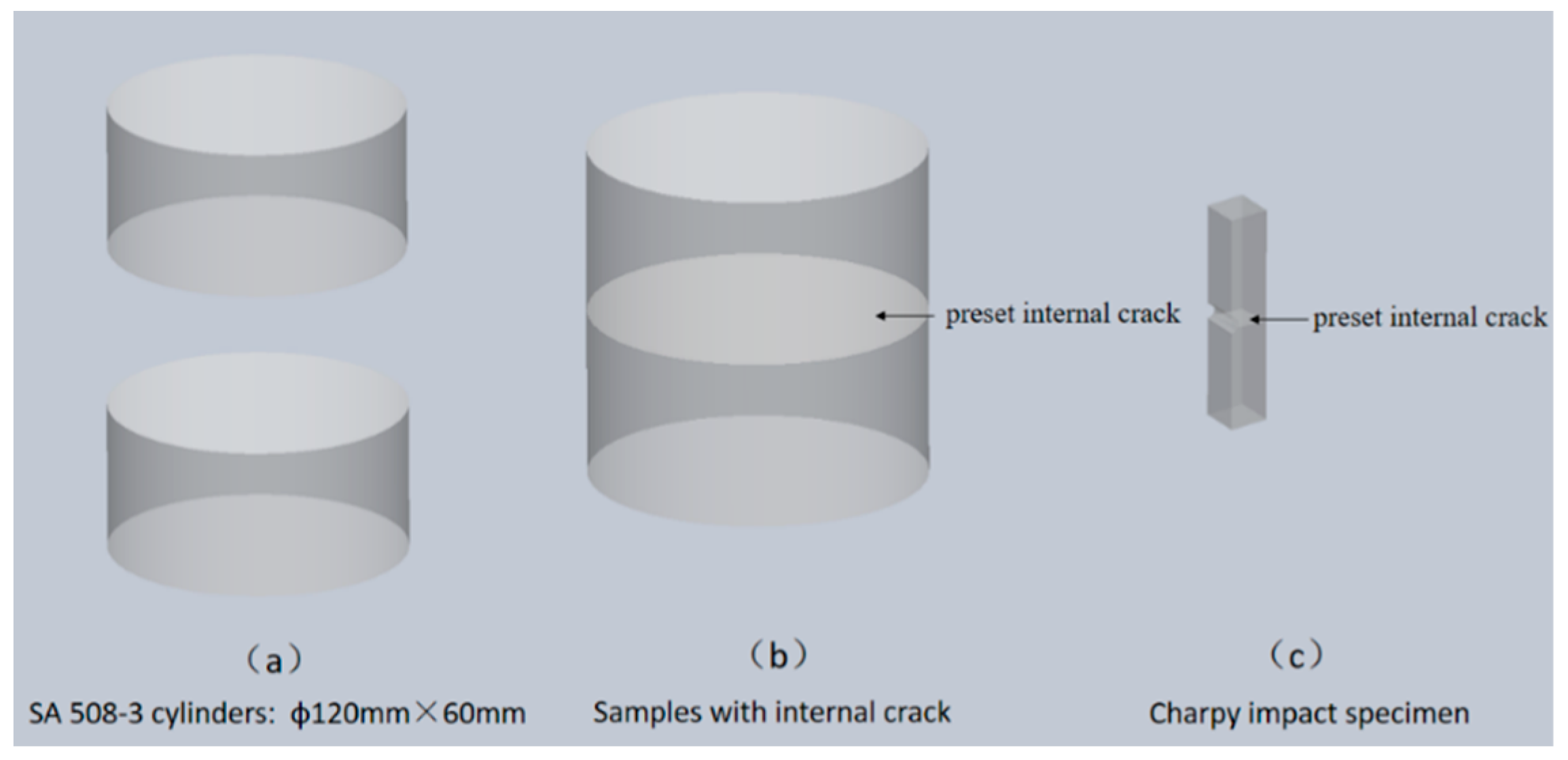
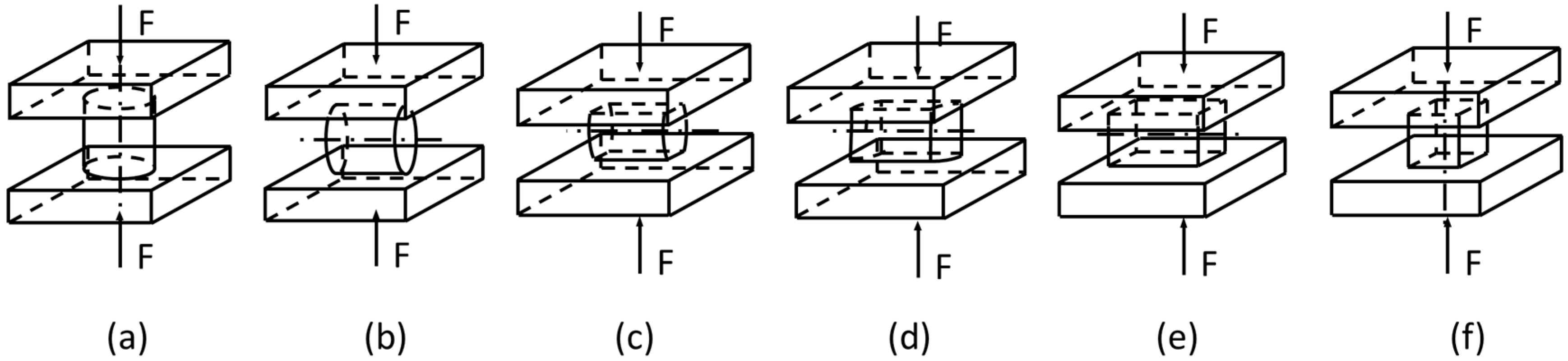
2. Methods
3. Results
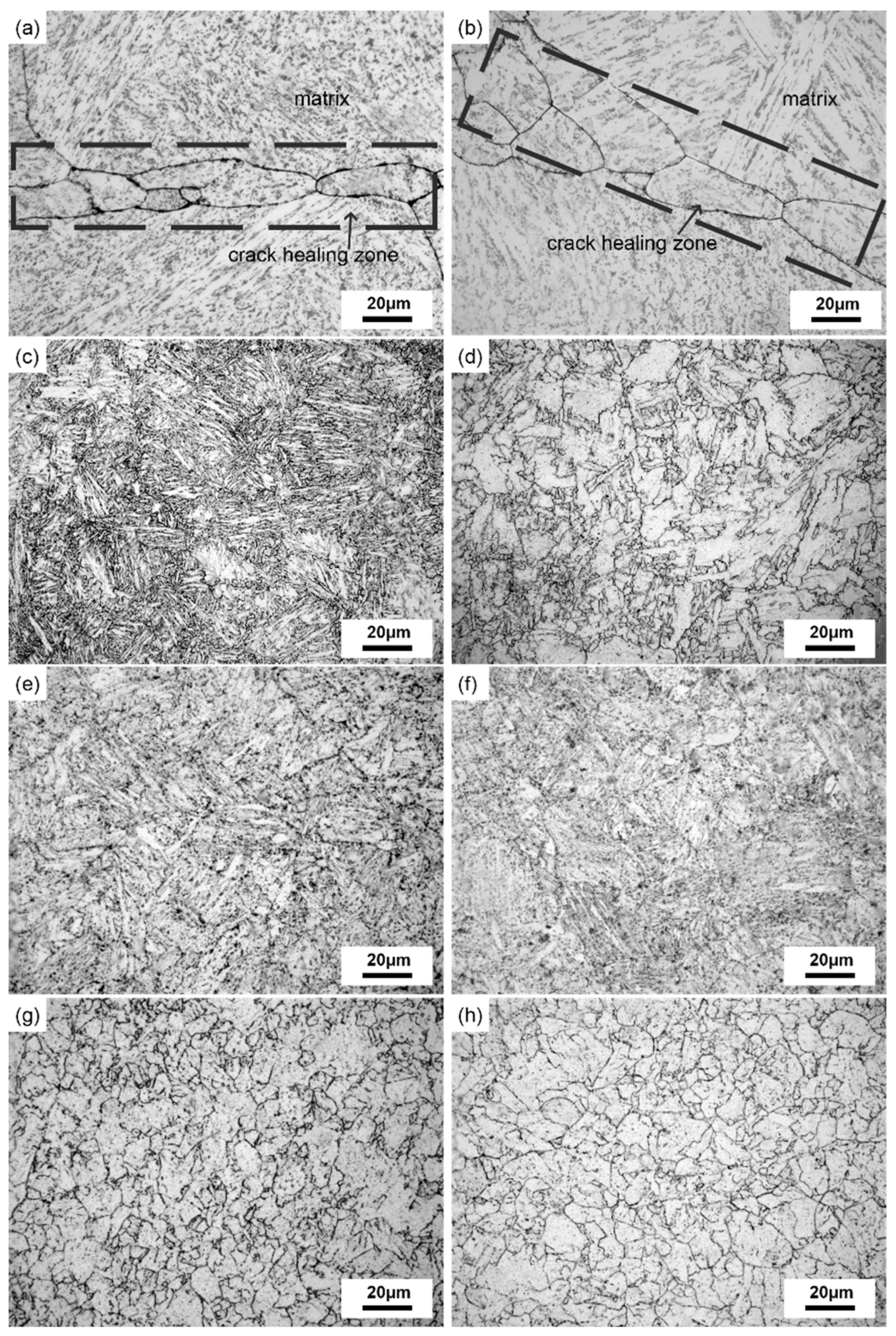
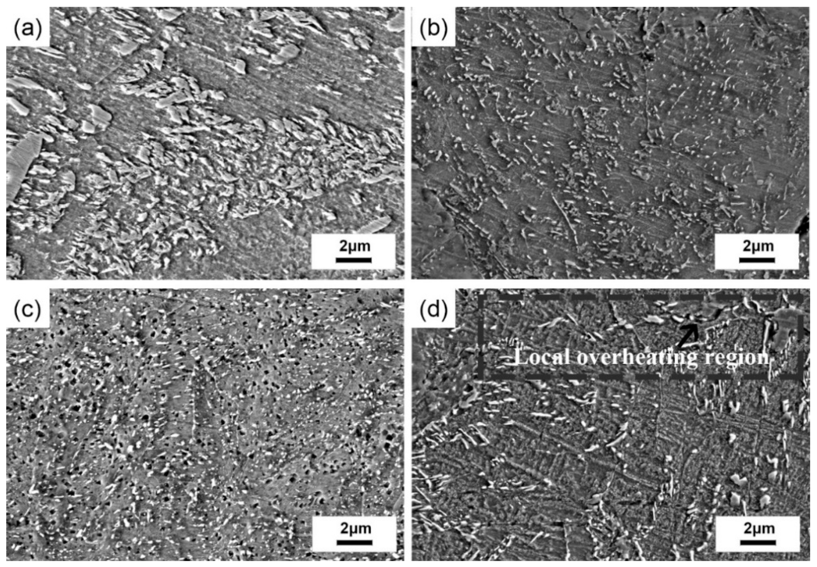
3.1. Microstructure Evolution of the Crack Healing Zone
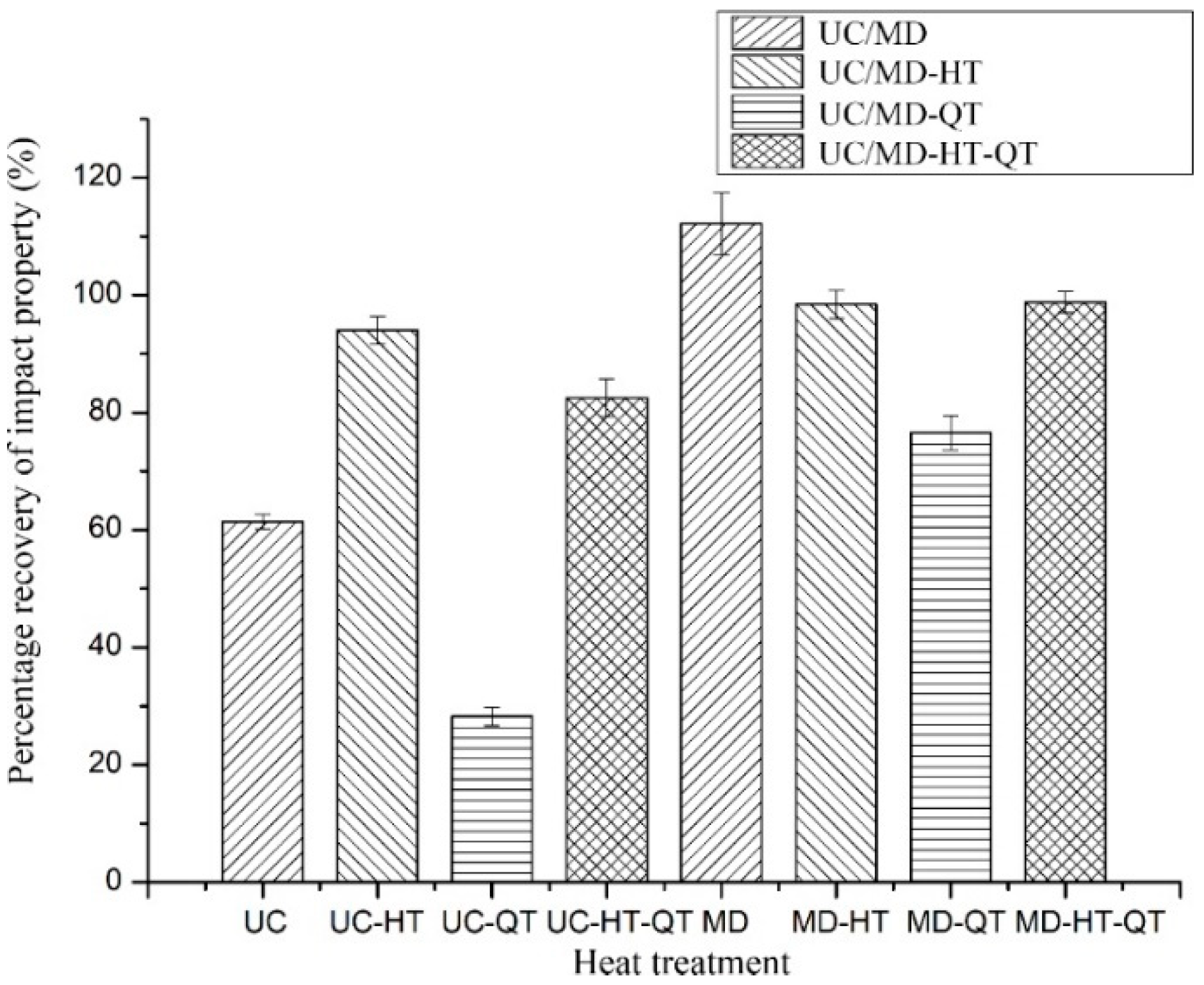
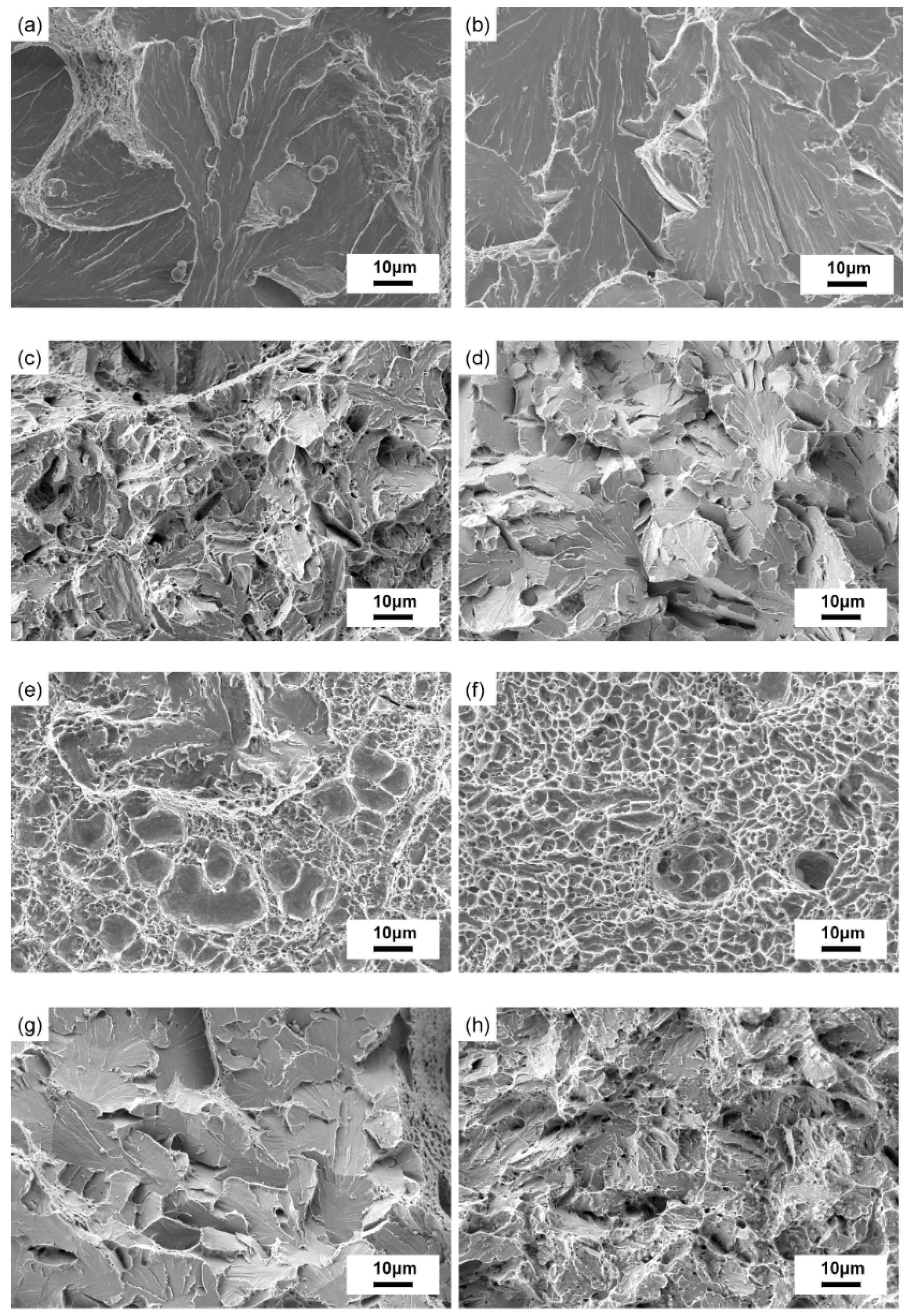
3.2. Impact Property of Crack Healing Zone
4. Discussion
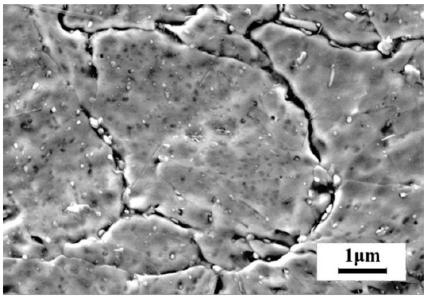
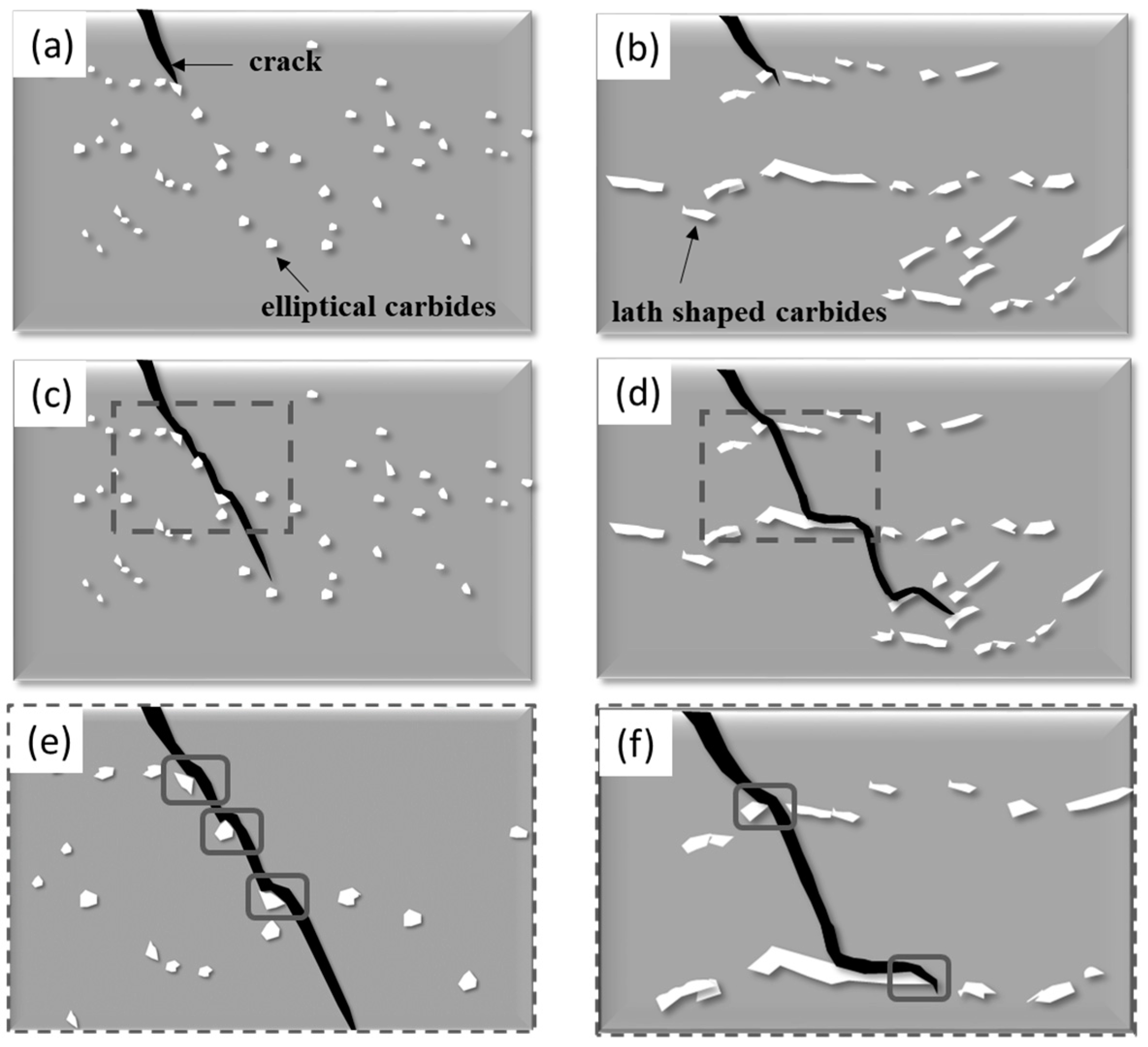
4.1. The Effect of Carbide Morphology on the Impact Property
4.2. The Effect of Heat Treatment Methods on the Impact Property
5. Conclusions
Author Contributions
Funding
Acknowledgments
Conflicts of Interest
References
- Zhang, Y.J.; Han, J.T. Analysis of microstructure of steel 20 in the range of healing of internal crack. Met. Sci. Heat Treat. 2012, 58, 526–528. [Google Scholar] [CrossRef]
- Wei, D.; Han, J.; Jiang, Z.Y.; Lu, C.; Tieu, A.K. A study on crack healing in 1045 steel. J. Mater. Process. Technol. 2006, 177, 233–237. [Google Scholar] [CrossRef]
- Xin, R.S.; Ma, Q.X.; Li, W.Q. Effect of Heat Treatment on Microstructure and Hardness of Internal Crack Healing in a Low Carbon Steel. Key Eng. Mater. 2017, 730, 3–7. [Google Scholar] [CrossRef]
- Yu, H.; Liu, X.; Li, X.; Godbole, A. Crack Healing in a Low-Carbon Steel under Hot Plastic Deformation. Metall. Mater. Trans. A 2014, 45, 1001–1009. [Google Scholar] [CrossRef]
- Meng, F.Y.; Nie, S.M. Inner Surface Migration during the Internal Crack Healing in 45 Steel. In Materials Science Forum; Trans Tech Publications Ltd.: Dalian, China, 2009; Volume 628, p. 547. [Google Scholar] [CrossRef]
- Xin, R.; Ma, Q.; Guo, D.; Li, W. Restoration of impact properties of internal crack healing in a low carbon steel. Mater. Sci. Eng. A 2017, 682, 433–440. [Google Scholar] [CrossRef]
- Qiu, Y.; Xin, R.; Luo, J.; Ma, Q. Crack Healing and Mechanical Properties Recovery in SA 508–3 Steel. Material 2019, 12, 890. [Google Scholar] [CrossRef]
- Hosoi, A.; Nagahama, T.; Ju, Y. Fatigue crack healing by a controlled high density electric current Field. Mater. Sci. Eng. A 2012, 533, 38–42. [Google Scholar] [CrossRef]
- Zhou, Y.; Guo, J.; Gao, M.; He, G. Crack healing in a steel by using electropulsing technique. Mater. Lett. 2004, 58, 1732–1736. [Google Scholar] [CrossRef]
- Mohtadi-Bonab, M.A.; Eskandari, M.; Szpunar, J.A. Role of cold rolled followed by annealing on improvement of hydrogen induced cracking resistance in pipeline steel. Eng. Fail. Anal. 2018, 91, 172–181. [Google Scholar] [CrossRef]
- Mohtadi-Bonab, M.A.; Ghesmati-Kucheki, H. Important factors on the failure of pipeline steels with focus on hydrogen induced cracks and improvement of their resistance. Met. Mater. Int. 2019, 25, 1109–1134. [Google Scholar] [CrossRef]
- Yan, G.; Han, L.; Li, C.; Luo, X.; Gu, J. Effect of macrosegregation on the microstructure and mechanical properties of a pressure-vessel steel. Metall. Mater. Trans. A 2017, 48, 3470–3481. [Google Scholar] [CrossRef]
- Liu, N.; Liu, Z.; He, X. Structure Inheritance Removing of SA508 Gr. 4n Steel for Nuclear Reactor Pressure Vessels. J. Iron Steel Res. 2017, 29, 402–410. [Google Scholar] [CrossRef]
- Zhou, Q.; Wu, X.; Shi, N. Microstructure evolution and kinetic analysis of DM hot-work die steels during tempering. Mater. Sci. Eng. A 2011, 528, 5696–5700. [Google Scholar] [CrossRef]
- Johnson, W.A.; Mehl, R.F. Reaction kinetics in processes of nucleation and growth. Trans. Metall. Soc. 1939, 135, 416–442. [Google Scholar]
- Avrami, M. Kinetics of phase change. I General theory. J. Chem. Phys. 1939, 7, 1103–1112. [Google Scholar] [CrossRef]
- Avrami, M. Kinetics of phase change. II transformation-time relations for random distribution of nuclei. J. Chem. Phys. 1940, 8, 212–224. [Google Scholar] [CrossRef]
- Avrami, M. Granulation, phase change, and microstructure kinetics of phase change. III. J. Chem. Phys. 1941, 9, 177–184. [Google Scholar] [CrossRef]
- Watté, P. Strain aging in heavily drawn eutectoid steel wires. Scr. Mater. 1996, 34, 89–95. [Google Scholar] [CrossRef]
- Li, X.; Zheng, Y.; Wu, X. Influence of Grain Size on Continuous Cooling Transformation Rules of a Bainitic Steel SDP1. Mater. Rep. 2017, 31, 86–92. [Google Scholar] [CrossRef]
- Takebayashi, S.; Ushioda, K.; Yoshinaga, N.; Ogata, S. Effect of Carbide Size Distribution on the Impact Toughness of Tempered Martensitic Steels with Two Different Prior Austenite Grain Sizes Evaluated by Instrumented Charpy Test. Mater. Trans. 2013, 54, 1110–1119. [Google Scholar] [CrossRef]
- Horn, R.M.; Ritchie, R. Mechanisms of Tempered Martensite Embrittlement in Low Alloy Steels. Metall. Trans. A 1978, 9, 1039–1053. [Google Scholar] [CrossRef]
- Yan, G.; Han, L.; Li, C.; Luo, X.; Gu, J. Characteristic of retained austenite decomposition during tempering and its effect on impact toughness in SA508 Gr. 3 steel. J. Nucl. Mater. 2017, 483, 167–175. [Google Scholar] [CrossRef]
- Qiu, Y.; Xin, R.; Luo, J.; Ma, Q. Effect of deformation modes and heat treatment on microstructure and impact property restoration of internal crack healing in SA 508-3 steel. Mater. Sci. Eng. A 2020, 778, 139073. [Google Scholar] [CrossRef]


| Sample | Deformation Modes | Heat Treatment | |
|---|---|---|---|
| Homogenization Treatment | Quenching and Tempering Treatment | ||
| UC | Uniaxial compression | - | - |
| UC-HT | Uniaxial compression | homogenization treatment | - |
| UC-QT | Uniaxial compression | - | quenching and tempering treatment |
| UC-HT-QT | Uniaxial compression | homogenization treatment | quenching and tempering treatment |
| MD | Multi-pass deformation | - | |
| MD-HT | Multi-pass deformation | homogenization treatment | - |
| MD-QT | Multi-pass deformation | - | quenching and tempering treatment |
| MD-HT-QT | Multi-pass deformation | homogenization treatment | quenching and tempering treatment |
| Healing Methods | Absorbed Energy in the Crack Healing Zone (J) | Standard Deviation (J) | Absorbed Energy in the Matrix (J) | Percentage Recovery (%) |
|---|---|---|---|---|
| UC | 8.93 | 1.02 | 14.54 | 61.40% |
| UC-HT | 31.36 | 2.11 | 33.34 | 94.06% |
| UC-QT | 61.75 | 4.62 | 218.82 | 28.22% |
| UC-HT-QT | 76.23 | 3.43 | 92.35 | 82.54% |
| MD | 19.41 | 2.88 | 17.30 | 112.20% |
| MD-HT | 33.45 | 5.12 | 33.98 | 98.44% |
| MD-QT | 170.34 | 8.13 | 222.56 | 76.54% |
| MD-HT-QT | 90.91 | 5.49 | 91.36 | 99.51% |
© 2020 by the authors. Licensee MDPI, Basel, Switzerland. This article is an open access article distributed under the terms and conditions of the Creative Commons Attribution (CC BY) license (http://creativecommons.org/licenses/by/4.0/).
Share and Cite
Qiu, Y.; Xin, R.; Luo, J.; Ma, Q. The Effects of Homogenizing and Quenching and Tempering Treatments on Crack Healing. Metals 2020, 10, 427. https://doi.org/10.3390/met10040427
Qiu Y, Xin R, Luo J, Ma Q. The Effects of Homogenizing and Quenching and Tempering Treatments on Crack Healing. Metals. 2020; 10(4):427. https://doi.org/10.3390/met10040427
Chicago/Turabian StyleQiu, Yao, Ruishan Xin, Jianbin Luo, and Qingxian Ma. 2020. "The Effects of Homogenizing and Quenching and Tempering Treatments on Crack Healing" Metals 10, no. 4: 427. https://doi.org/10.3390/met10040427
APA StyleQiu, Y., Xin, R., Luo, J., & Ma, Q. (2020). The Effects of Homogenizing and Quenching and Tempering Treatments on Crack Healing. Metals, 10(4), 427. https://doi.org/10.3390/met10040427