Failure Mechanisms of Mechanically and Thermally Produced Holes in High-Strength Low-Alloy Steel Plates Subjected to Fatigue Loading


Abstract
:1. Introduction
2. Materials and Methods
2.1. Material
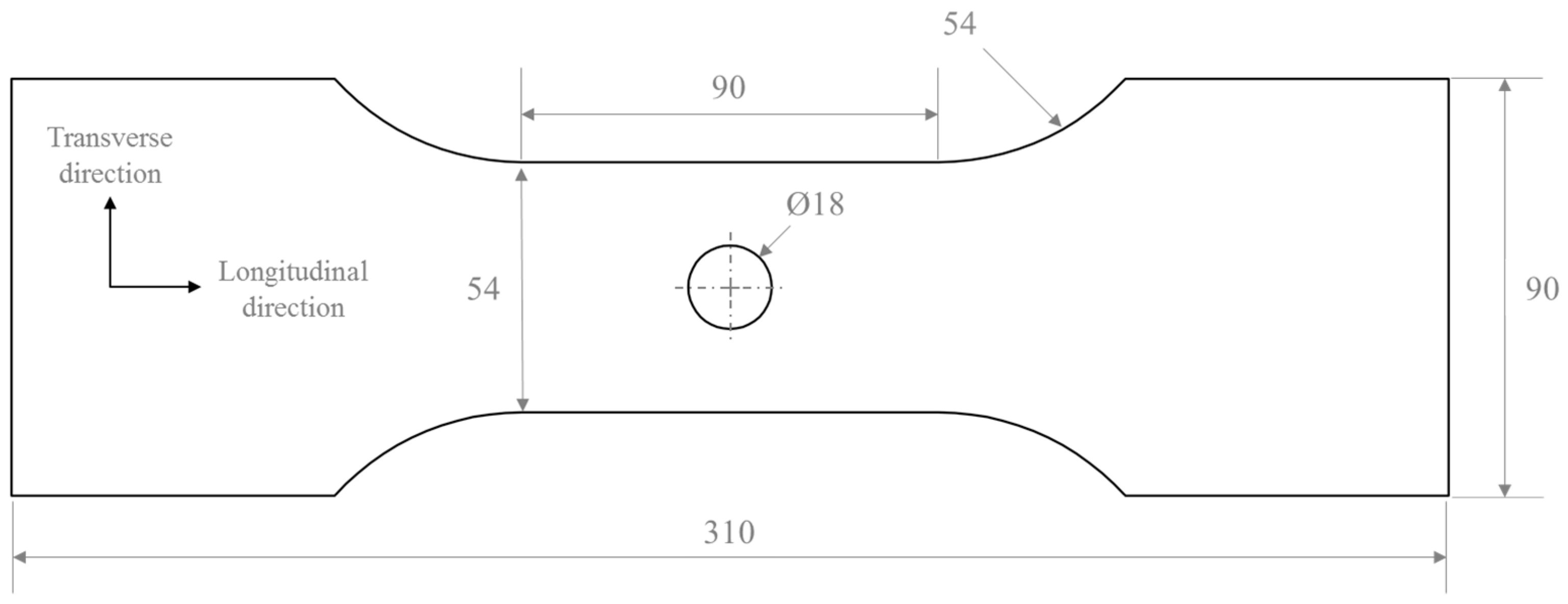
2.2. Sample Design
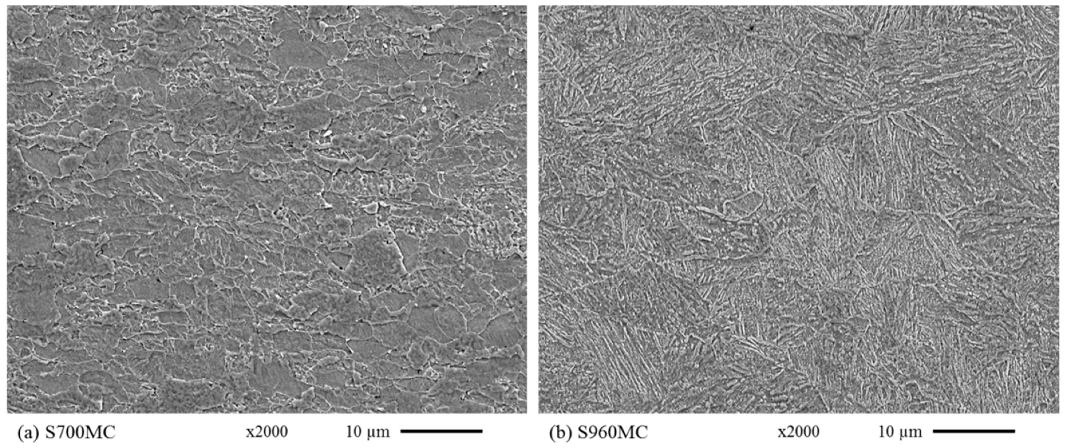
2.3. Microstructural Characterization
2.4. Hole-Making Procedures
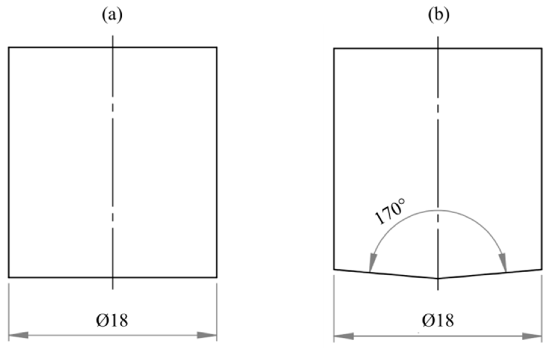
2.5. Hole Geometry Evaluation
2.6. Surface Profiling
2.7. Micro Hardness Mapping
2.8. Residual Stresses
2.9. Fatigue Testing
3. Results and Discussion
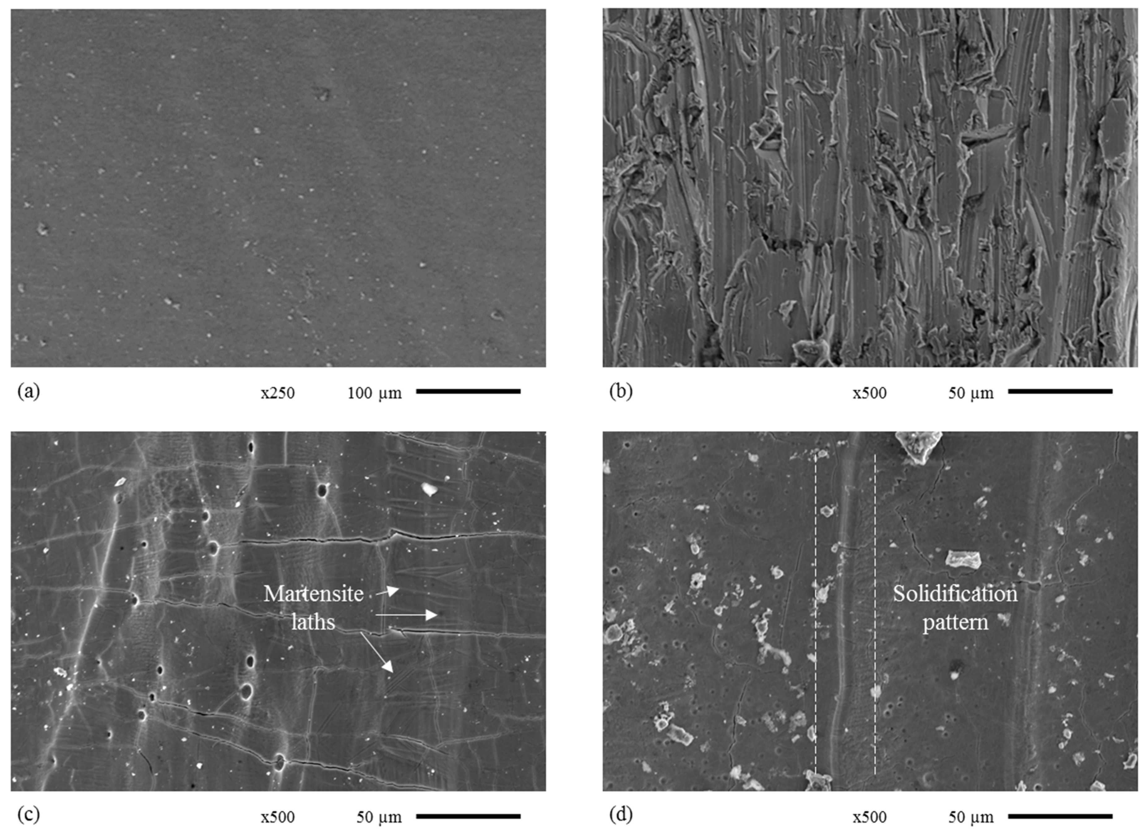
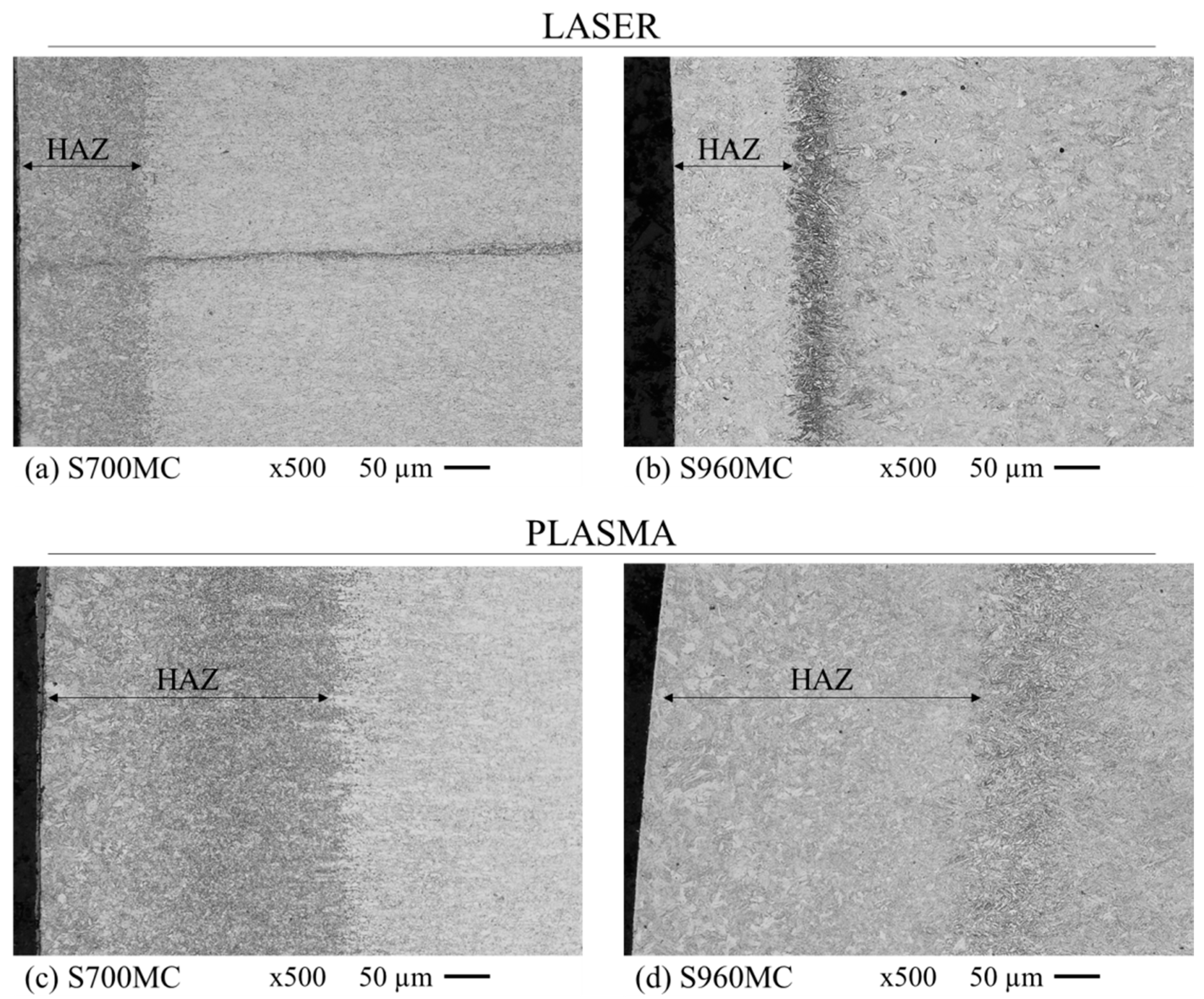
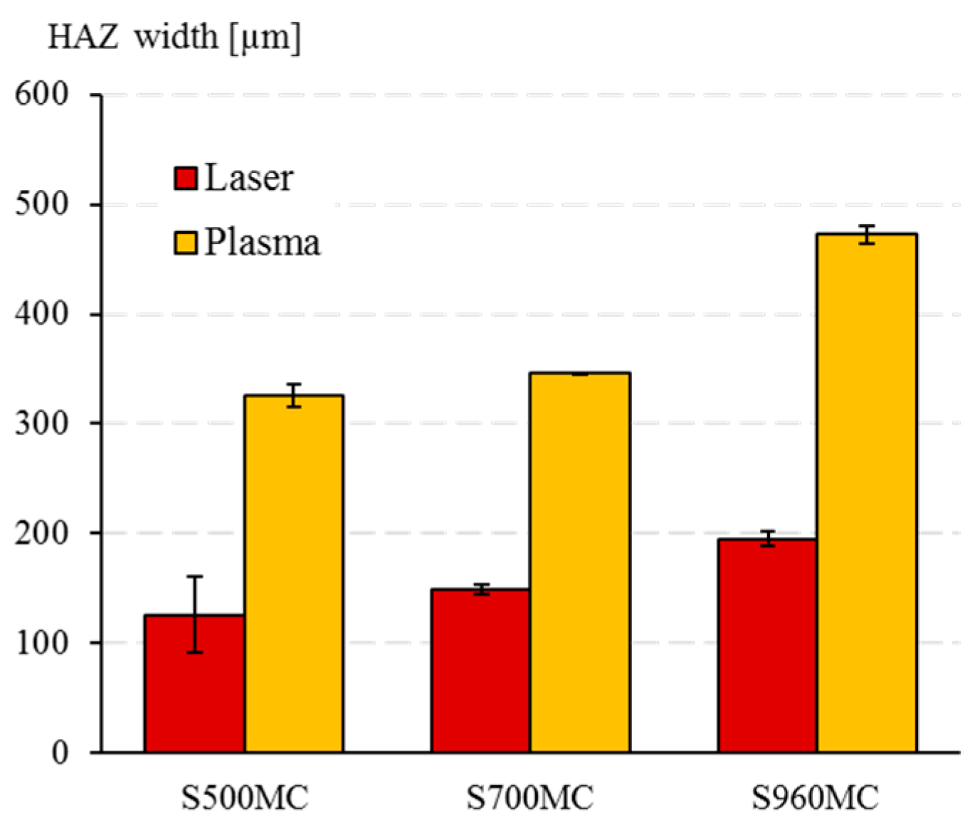
3.1. Microstructural Characterization
3.2. Hole Surface Evaluation
3.3. Surface Topology Evaluation
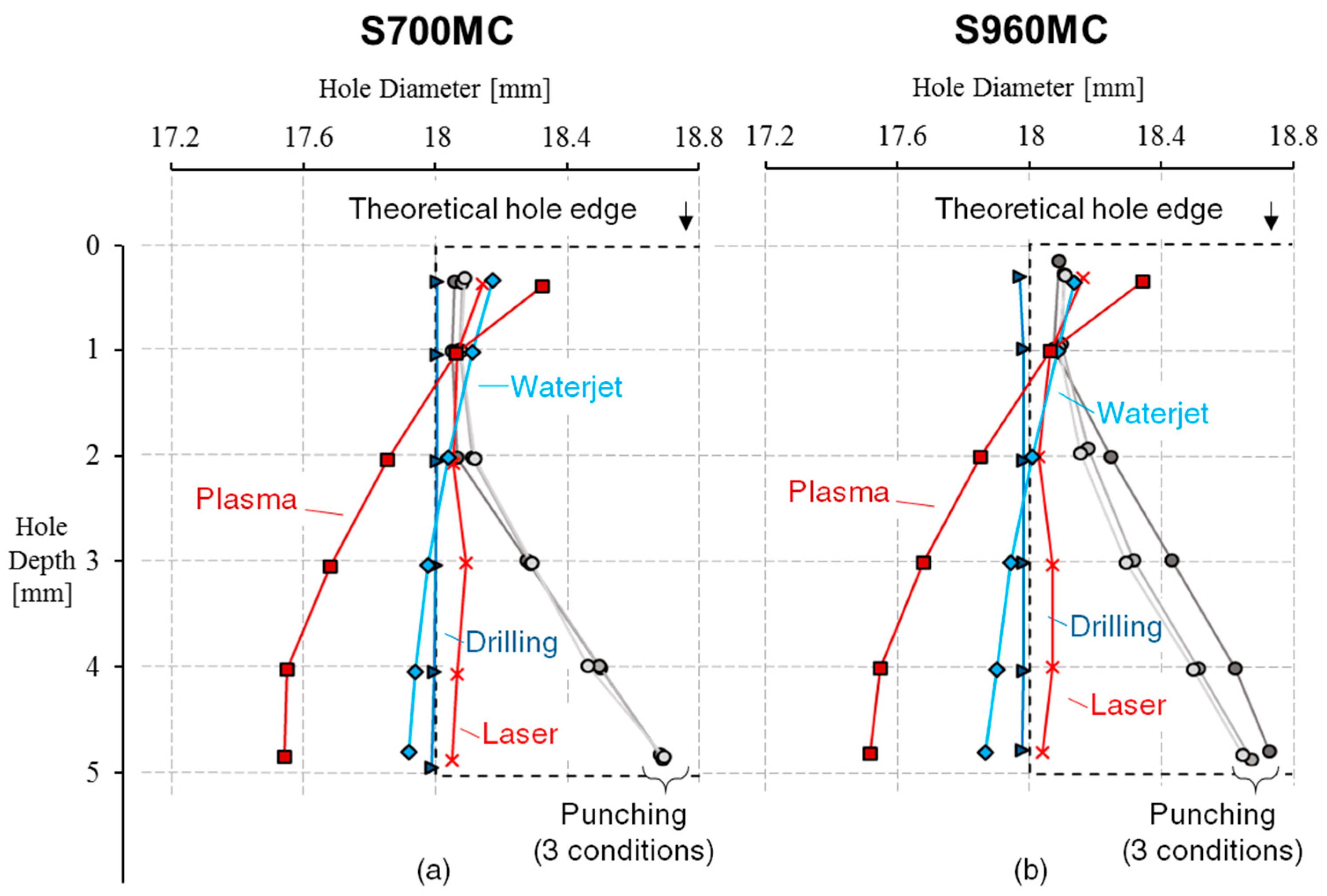
3.4. Hole Geometry Evaluation
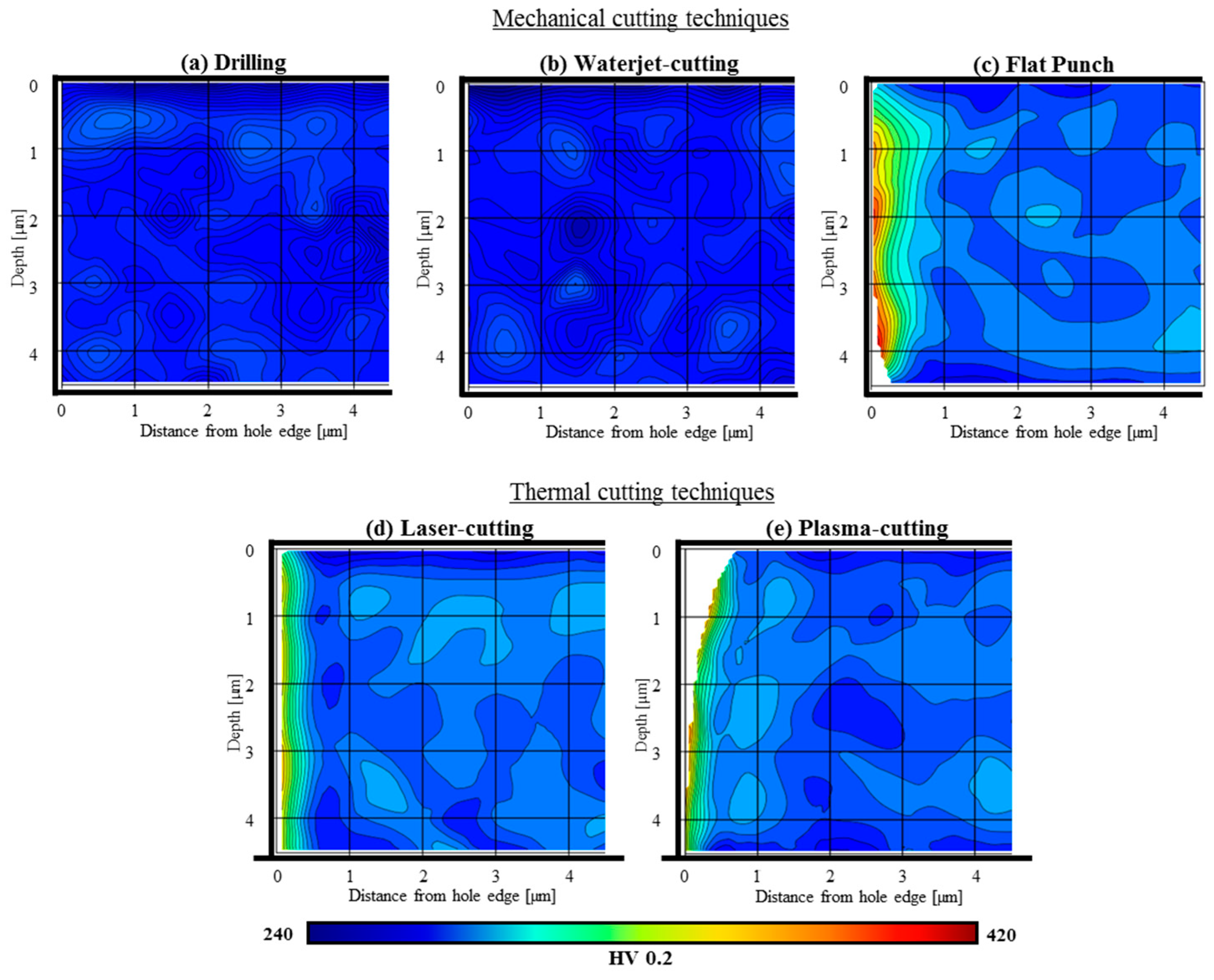
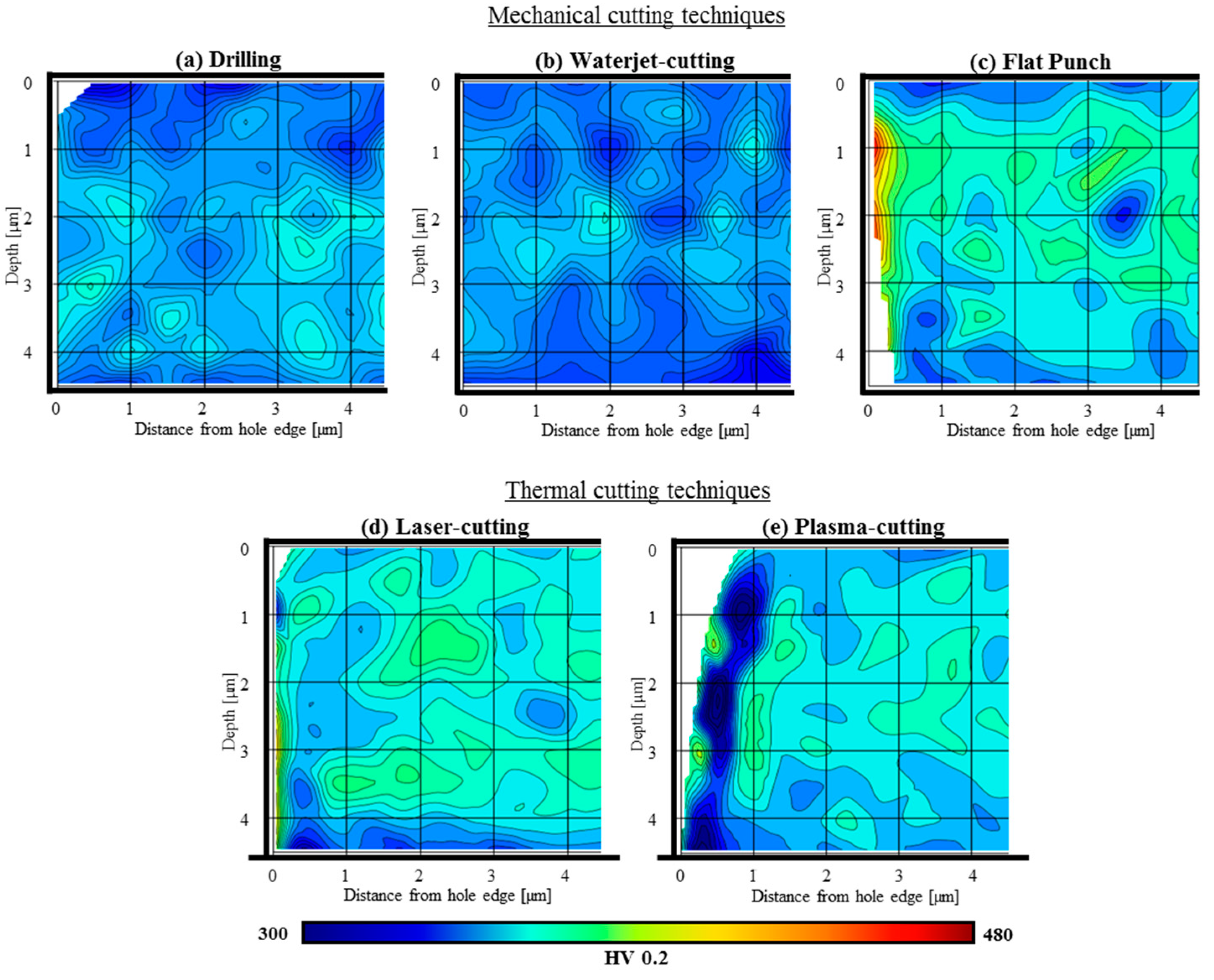
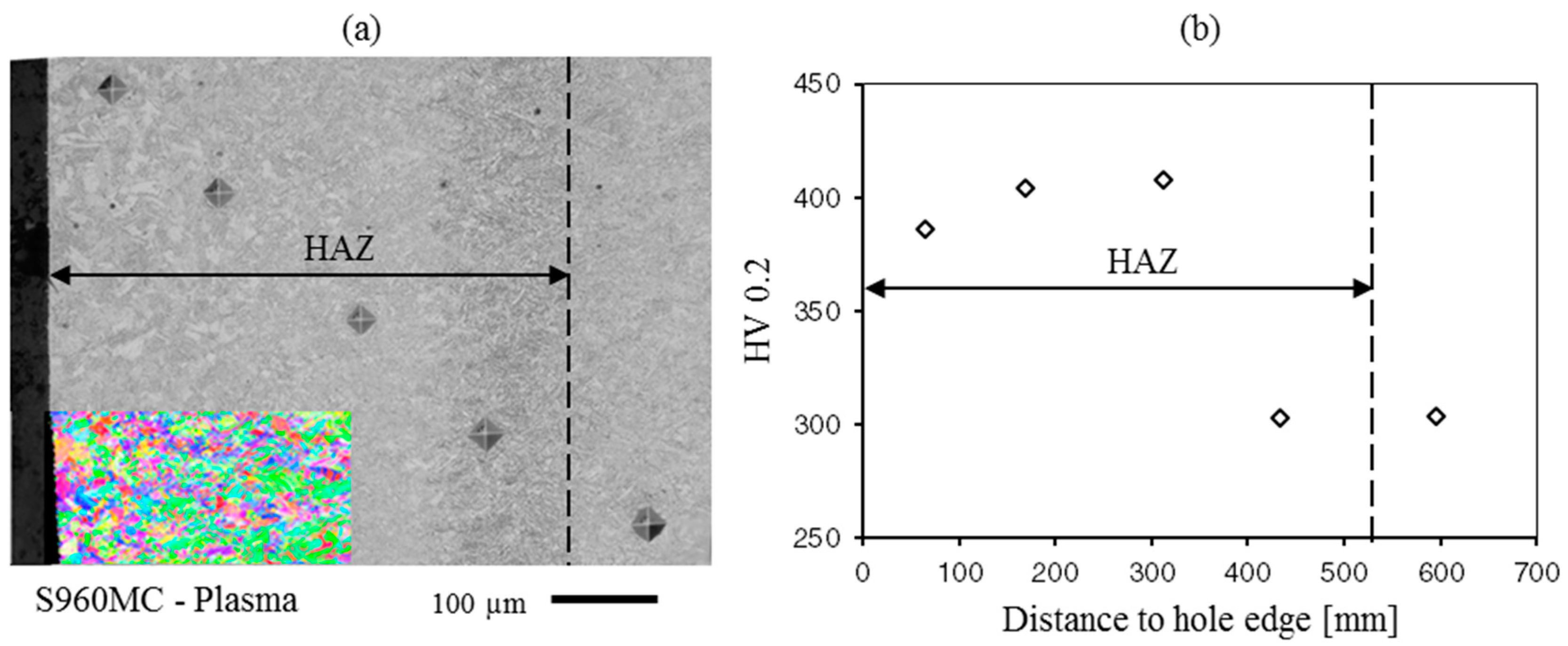
3.5. Micro-Hardness Evaluation
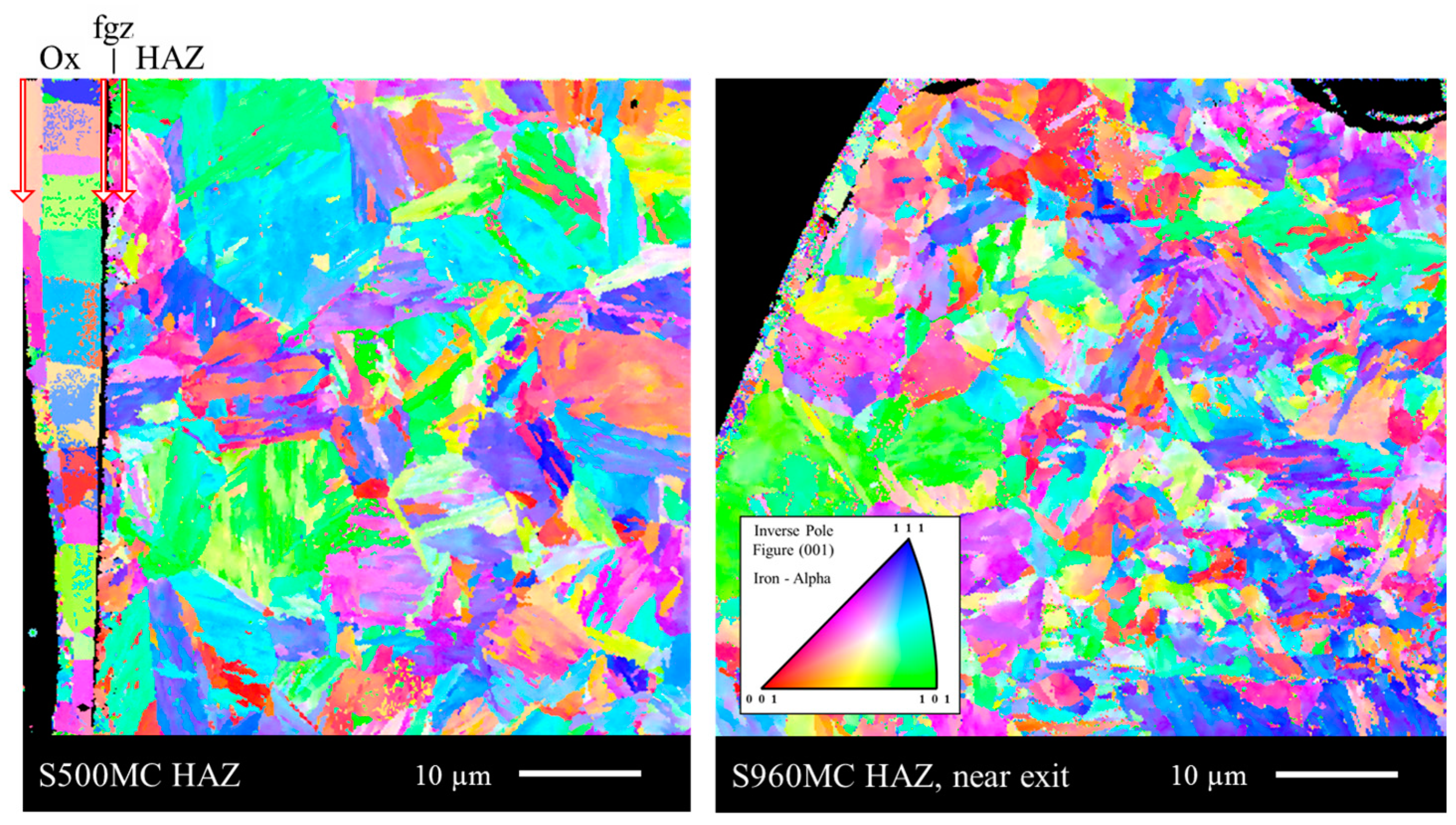
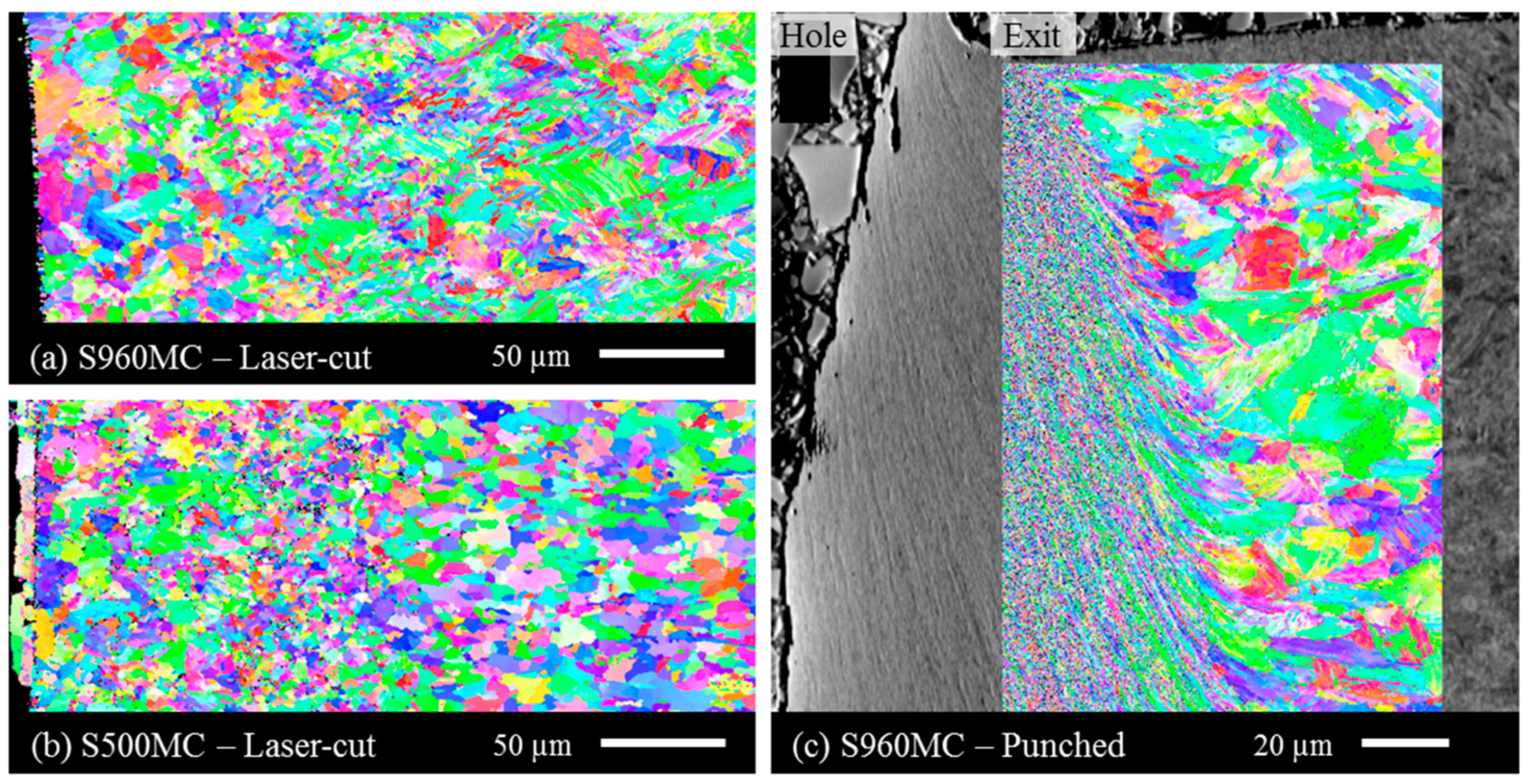
3.6. EBSD
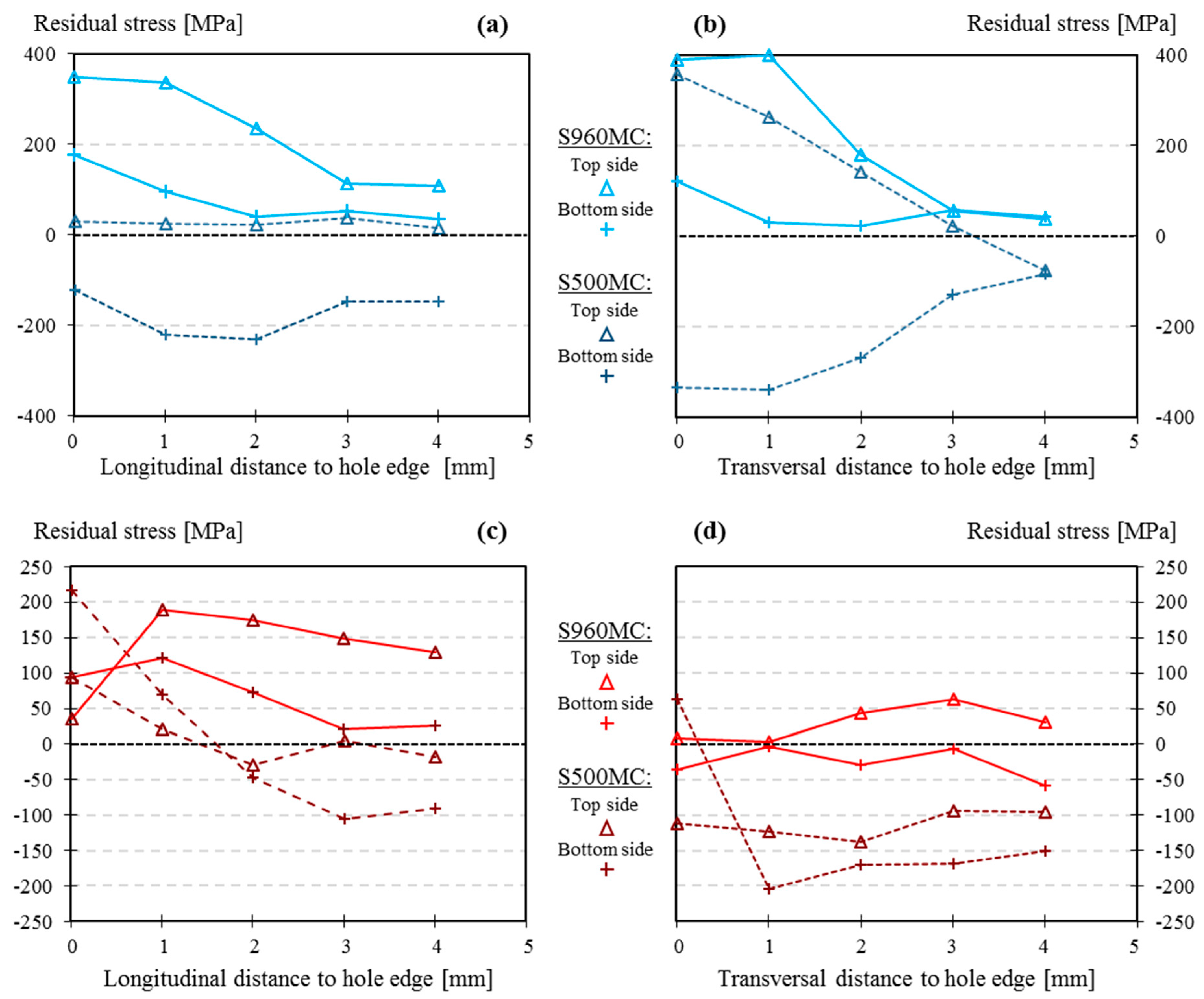
3.7. Residual Stress
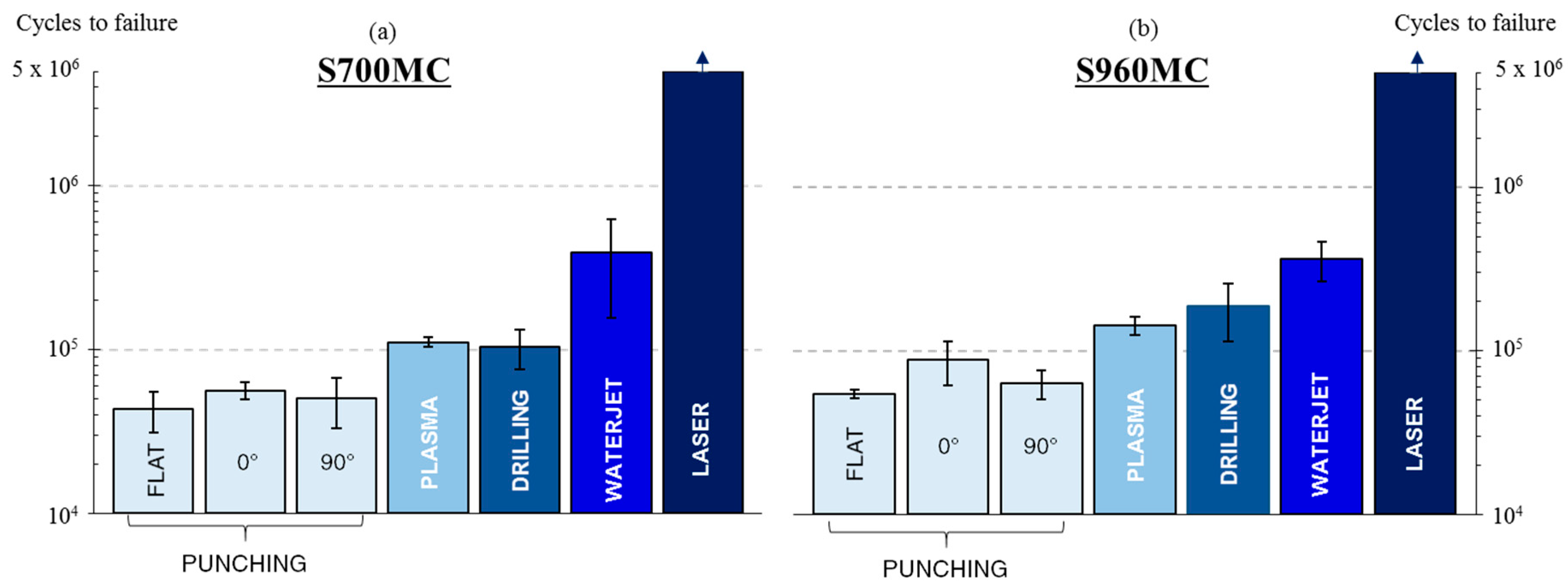
3.8. Fatigue Results
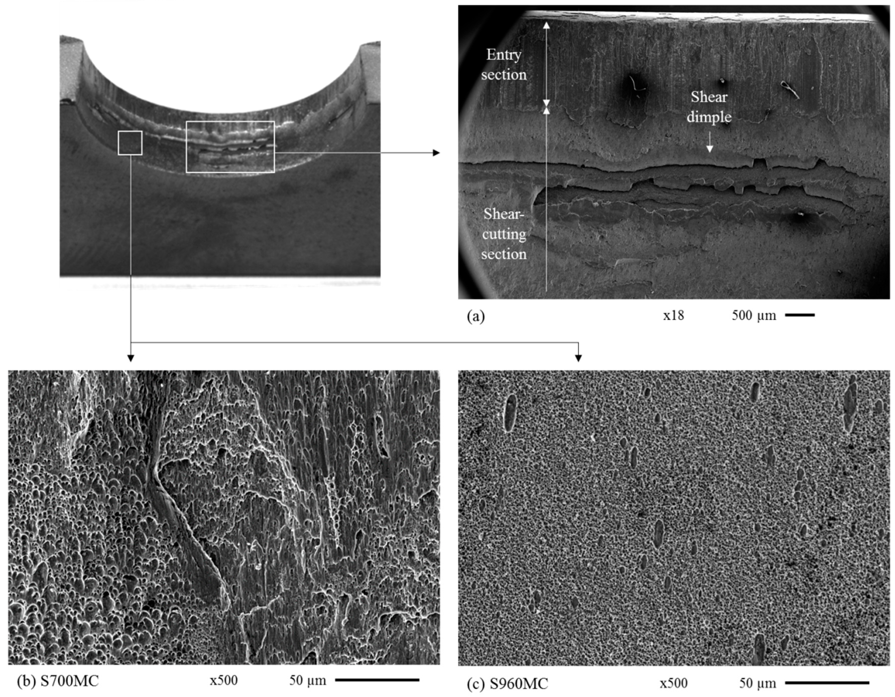
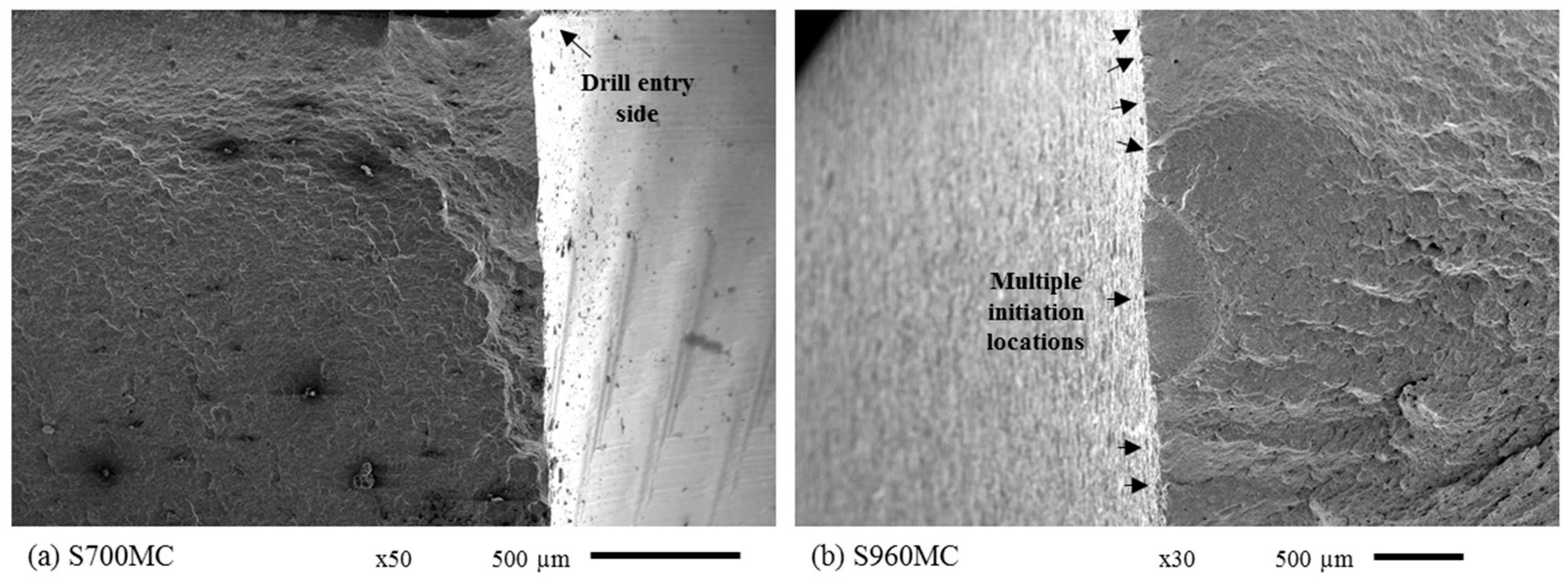
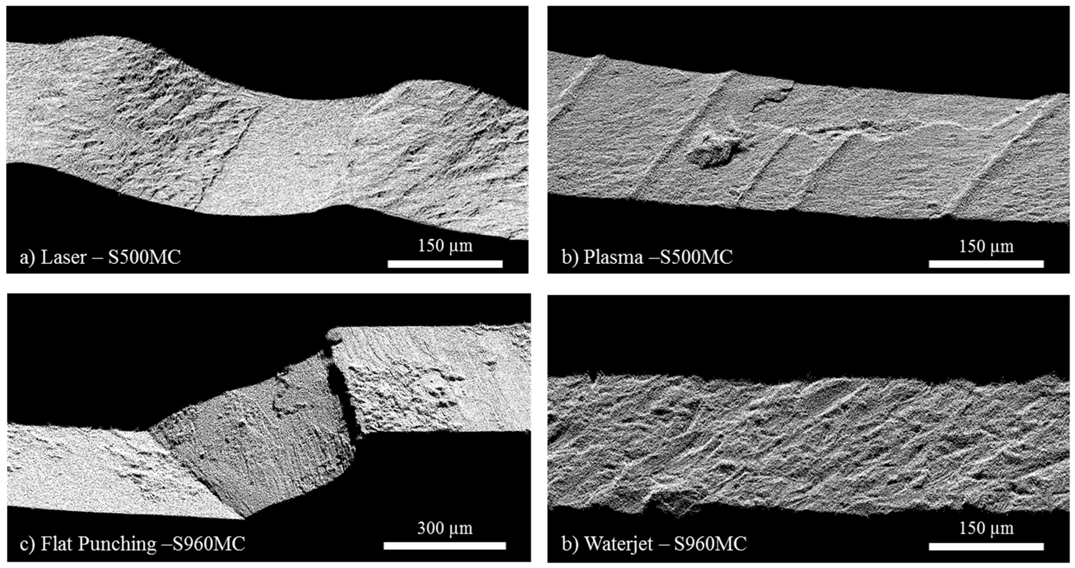
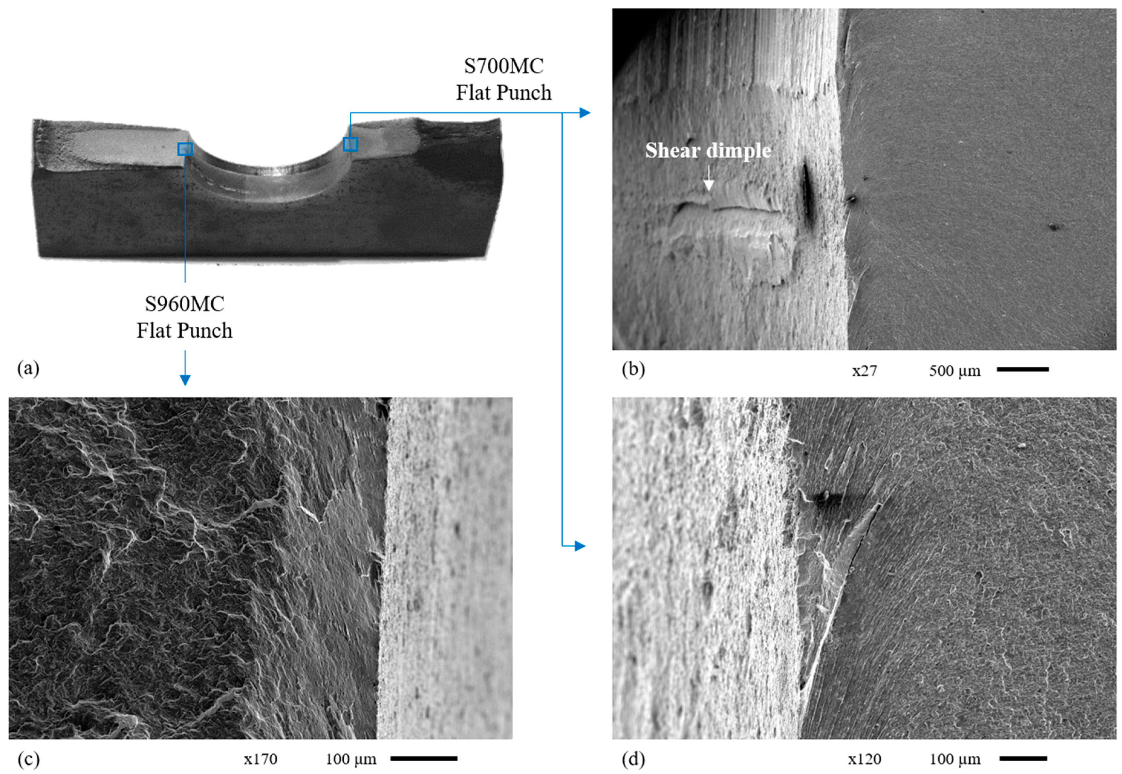
3.9. Fracture Analysis
4. Conclusions
Author Contributions
Funding
Conflicts of Interest
References
- Gogou, E. Use of High Strength Steel Grades for Economical Bridge Design. Ph.D. Thesis, TU Delft, Delft University of Technology, Delft, The Netherlands, 2012. [Google Scholar]
- Schröter, F.; Schütz, W. State of art in the production and use of high-strength heavy plates for hydropower applications. In Proceedings of the High Strength Steel for Hydropower Plants, Graz, Austria, 5–6 July 2005. [Google Scholar]
- Jensen, L.; Bloomstine, M.L. Application of high strength steel in super long span modern suspension bridge design. In Proceedings of the Nordic Steel Construction Conference, Stockholm, Sweden, 2–4 September 2009. [Google Scholar]
- Miki, C.; Homma, K.; Tominaga, T. High strength and high performance steels and their use in bridge structures. J. Constr. Steel Res. 2002, 58, 3–20. [Google Scholar] [CrossRef]
- Willms, R. High strength steel for steel constructions. In Proceedings of the Nordic Steel Construction Conference-NSCC, Malmö, Sweden, 2–4 September 2009; pp. 597–604. [Google Scholar]
- Gresnigt, A.; Steenhuis, C. High strength steels. Prog. Struct. Eng. Mater. 1997, 1, 31–41. [Google Scholar] [CrossRef]
- Billingham, J.; Sharp, J.; Spurrier, J.; Kilgallon, P. Review of the Performance of High Strength Steels Used Offshore; Health and Safety Executive: Bootle, UK, 2003; p. 111. [Google Scholar]
- Bailey, N.; Coe, F.R.; Gooch, T.; Hart, P.; Jenkins, N.; Pargeter, R. Welding Steels without Hydrogen Cracking; Woodhead Publishing: Sawston, UK, 1993. [Google Scholar]
- Tamura, I.; Sekine, H.; Tanaka, T. Thermomechanical Processing of High-Strength Low-Alloy Steels; Butterworth-Heinemann: Oxford, UK, 2013. [Google Scholar]
- Braconi, A.; Osta, A.; Cama, P.; Blasi, N.; Mordini, A.; Wenzel, H.; Chellini, G.; Lippi, F.; Salvatore, W.; Rauert, T.; et al. Design for Optimal Performance of High-Speed Railway Bridges by Enhanced Monitoring Systems (Details); EU Publications: Bruxelles, Belgium, 2013. [CrossRef]
- European Commission. Improving the Fatigue Life of High Strength Steel Welded Structures by Post Weld Treatments and Specific Filler Material (FATWELDHSS); Directorate-General for Research and Innovation (European Commission): Brussels, Belgium, 2010. [Google Scholar]
- Jiménez-Peña, C.; Talemi, R.H.; Rossi, B.; Debruyne, D. Investigations on the fretting fatigue failure mechanism of bolted joints in high strength steel subjected to different levels of pre-tension. Tribol. Int. 2017, 108, 128–140. [Google Scholar] [CrossRef]
- Jiménez-Peña, C.; Goulas, C.; Rossi, B.; Debruyne, D. Influence of hole-making procedures on fatigue behaviour of high strength steel plates. J. Constr. Steel Res. 2019, 158, 1–14. [Google Scholar] [CrossRef]
- Valtinat, G.; Huhn, H. Bolted connections with hot dip galvanized steel members with punched holes. In Proceedings of the Connections in Steel Structures V, Amsterdam, The Netherlands, 3–5 July 2004; pp. 297–310. [Google Scholar]
- Goldberg, F. Influence of thermal cutting and its quality on the fatigue strength of steel. Weld. J. 1973, 52, 392–404. [Google Scholar]
- Bannister, A.; Skalidakis, M.; Pariser, A.; Langenberg, P.; Gutierrez-Solana Salcedo, F.; Sánchez, L.; Pesquera, D.; Azpiazu, W. Performance Criteria for Cold Formed Structural Steels; EU Publications: Brussels, Belgium, 2006; pp. 1–241.
- European Commission. High Performance Cut Edges in Structural Steel Plates for Demanding Applications (HIPERCUT); Directorate-General for Research and Innovation (European Commission): Brussels, Belgium, 2016. [Google Scholar]
- AASHTO. AASHTO LRFD Bridge Design Specifications; Fourth Edition with 2008 Interim Revisions; American Association of State Highway and Transportation Officials: Washington, DC, USA, 2012. [Google Scholar]
- British Standards Institution. Code of Practice for Fatigue Design and Assessment of Steel Structures; British Standards Institution: London, UK, 1993. [Google Scholar]
- Eurocode—Basis of Structural. EN 1990: 2002—Basis of Structural Design; British Standard Institution: London, UK, 2002. [Google Scholar]
- CEN. EN 1993-1-12. Eurocode 3: Design of Steel Structures—Part 1–12: Additional Rules for the Extension of EN 1993 Up to Steel Grades S 700; European Committee for Standardization: Brussels, Belgium, 2007. [Google Scholar]
- Denys, K.; Coppieters, S.; Seefeldt, M.; Debruyne, D. Multi-DIC setup for the identification of a 3D anisotropic yield surface of thick high strength steel using a double perforated specimen. Mech. Mater. 2016, 100, 96–108. [Google Scholar] [CrossRef]
- SSAB. Strenx® 960 MC. Available online: https://www.ssab.com/products/brands/strenx/products/strenx-960-mc?accordion=downloads (accessed on 1 December 2019).
- Arcelormittal. Amstrong—High Strength Steels. 2018. Available online: http://industry.arcelormittal.com/catalogue/A20/EN (accessed on 1 December 2019).
- EN, B. 1-9 (2005): Design of Steel Structures; Part 1.9: Fatigue; British Standards Institution: London, UK, 1993. [Google Scholar]
- VariDrill™ Catalogue. Available online: https://www.widia.com/en/products/24019771/24064245/46993284/100006851.html (accessed on 21 February 2019).
- ISO, E. 6507-1: 2005-Metallic Materials-Vickers Hardness Test; European Committee for Standardization: Brussels, Belgium, 2006. [Google Scholar]
- Prevey, P.S. X-ray diffraction residual stress techniques. Asm Int. Asm Handb. 1986, 10, 380–392. [Google Scholar]
- Guo, F.; Wang, X.; Liu, W.; Shang, C.; Misra, R.; Wang, H.; Zhao, T.; Peng, C. The Influence of Centerline Segregation on the Mechanical Performance and Microstructure of X70 Pipeline Steel. Steel Res. Int. 2018, 89, 1800407. [Google Scholar] [CrossRef]
- Schwartz, A.J.; Kumar, M.; Adams, B.L.; Field, D.P. Electron. Backscatter Diffraction in Materials Science; Springer: New York, NY, USA, 2000. [Google Scholar]
- Janarthanam, H.; Sommer, S.; Carl, E.-R.; Preußner, J.; Huberth, F. Numerical prediction of damage in punching process using shear modified Gurson model. In Proceedings of the 4th European Steel Technology and Application Days, Düsseldorf, Germany, 24–28 June 2019. [Google Scholar]


| Chemical Composition (wt.%) | |||||||||||||||
|---|---|---|---|---|---|---|---|---|---|---|---|---|---|---|---|
| Grade | C | Si | Mn | P | S | Al | Nb | V | Ti | Mo | B | ||||
| S500MC | ≤0.120 | ≤0.500 | ≤1.700 | ≤0.025 | ≤0.015 | 0.015 | ≤0.090 | ≤0.200 | ≤0.150 | - | - | ||||
| S700MC | ≤0.120 | ≤0.600 | ≤2.100 | ≤0.025 | ≤0.015 | ≥0.015 | ≤0.090 | ≤0.200 | ≤0.220 | ≤0.5 | ≤0.0050 | ||||
| S960MC | ≤0.120 | ≤0.250 | ≤1.300 | ≤0.020 | ≤0.010 | ≥0.015 | ≤0.050 | ≤0.050 | ≤0.070 | - | - | ||||
| Mechanical properties | |||||||||||||||
| Grade | Young modulus (GPa) | Yield stress (MPa) | UTS (MPa) | Elongation (%) | Hardness (HV0.2) | ||||||||||
| S500MC | 210 | 562 ± 6 | 658 ± 4 | 13.7 ± 1.2 | 207 ± 7 | ||||||||||
| S700MC | 210 | 731 ± 3 | 801 ± 4 | 11.8 ± 0.6 | 266 ± 9 | ||||||||||
| S960MC | 210 | 977 ± 7 | 1061 ± 8 | 3.2 ± 0.2 | 344 ± 6 | ||||||||||
| Punching | |||
|---|---|---|---|
| Max. punching speed | 20 m/min | ||
| Cutting clearance | 0.8 mm | ||
| Punch type | Flat | Chamfered | Chamfered |
| Alignment | - | 0° | 90° |
| Drilling | |||
| Cutting speed | 80 m/min | ||
| Feed | 0.3 mm/rev | ||
| Coolant | Flood | ||
| Material Removal rate | 108.02 cm3/min | ||
| Torque at tool | 31.92 Nm | ||
| Waterjet | |||
| Normal offset | 1.27 mm | ||
| Radial offset | 0.32 mm | ||
| High pressure setting | 379.2 MPa (55,000 psi) | ||
| Low Pressure setting | 137.9 MPa (20,000 psi) | ||
| Mixing tube diameter | 0.762 mm | ||
| Jewel diameter | 0.3048 mm | ||
| Abrasive flow rate | 0.3073 Kg/min | ||
| Laser | |||
| Beam power | 4000 W | ||
| Cutting speed | 6.5 m/min | ||
| Nozzle diameter | 0.8 mm | ||
| Nozzle distance | 0.7 mm | ||
| Focus diameter | −1.8 mm | ||
| Plasma | |||
| Current | 100 A | ||
| Nozzle | 4.1/1.4 (mm) | ||
| Speed | 2159 mm/min | ||
| Torche standoff | 4 mm | ||
| Height control | Not Active | ||
© 2020 by the authors. Licensee MDPI, Basel, Switzerland. This article is an open access article distributed under the terms and conditions of the Creative Commons Attribution (CC BY) license (http://creativecommons.org/licenses/by/4.0/).
Share and Cite
Jiménez-Peña, C.; Goulas, C.; Preußner, J.; Debruyne, D. Failure Mechanisms of Mechanically and Thermally Produced Holes in High-Strength Low-Alloy Steel Plates Subjected to Fatigue Loading. Metals 2020, 10, 318. https://doi.org/10.3390/met10030318
Jiménez-Peña C, Goulas C, Preußner J, Debruyne D. Failure Mechanisms of Mechanically and Thermally Produced Holes in High-Strength Low-Alloy Steel Plates Subjected to Fatigue Loading. Metals. 2020; 10(3):318. https://doi.org/10.3390/met10030318
Chicago/Turabian StyleJiménez-Peña, Carlos, Constantinos Goulas, Johannes Preußner, and Dimitri Debruyne. 2020. "Failure Mechanisms of Mechanically and Thermally Produced Holes in High-Strength Low-Alloy Steel Plates Subjected to Fatigue Loading" Metals 10, no. 3: 318. https://doi.org/10.3390/met10030318
APA StyleJiménez-Peña, C., Goulas, C., Preußner, J., & Debruyne, D. (2020). Failure Mechanisms of Mechanically and Thermally Produced Holes in High-Strength Low-Alloy Steel Plates Subjected to Fatigue Loading. Metals, 10(3), 318. https://doi.org/10.3390/met10030318