Article

Effect of SLM Processing Parameters on Microstructures and Mechanical Properties of Al0.5CoCrFeNi High Entropy Alloys

State Key Laboratory for Mechanical Behavior of Materials, Xi’an Jiaotong University, Xi’an 710049, China
*
Author to whom correspondence should be addressed.
Metals 2020, 10(2), 292; https://doi.org/10.3390/met10020292
Submission received: 26 December 2019 / Revised: 18 February 2020 / Accepted: 19 February 2020 / Published: 23 February 2020

Abstract

:
Selective laser melting (SLM) to fabricate Al0.5CoCrFeNi high entropy alloys with pre-mixed powders was studied in this paper. The influences of process parameters including laser power, scanning speed, and hatch spacing on the relative density of high-entropy alloys (HEAs) were investigated. A relative density of 99.92% can be achieved by optimizing the SLM process parameters with laser power 320 W, scanning speed 800 mm/s, and hatch spacing of 60 μm, respectively. Moreover, the microstructure of the HEAs was also studied using scanning electron microscopy (SEM) and x-ray diffraction (XRD). It was found that the microstructure of the HEAs was only composed of face-centered cubic and body-centered cubic phases, without complex intermetallic compounds. The mechanical properties of the HEAs were also characterized. At ambient temperature, the alloys had a high yield strength of about 609 MPa, tensile strength about 878 MPa, and hardness about 270 HV. Through a comparison with the corresponding alloys fabricated by vacuum induction melting, it can be concluded that the high entropy alloys fabricated by SLM had fine microstructures and improved mechanical properties.

1. Introduction

Traditional alloy design is limited to one element as the main component with the addition of another or more of the metallic and non-metallic elements to obtain a particular performance. However, the traditional concept restricts the mechanical properties of the alloy, which are greatly affected by the main component. A novel alloy design concept, multi-element high entropy alloys (HEAs), was first proposed by Jien-Wei Yeh [1,2]. HEAs composed of five to 13 metallic and non-metallic elements in equimolar or near-equimolar ratios break the traditional design concept [3,4]. Many experimental studies [5] showed that: (i) HEAs possess a single body-centered cubic, face-centered cubic, or mixed, close-packed or amorphous structures, rather than complex intermetallic compounds due to the high-entropy effect; and (ii) HEAs have a better performance such as anti-softening, high hardness, wear resistance, corrosion resistance, and other interesting properties at room or elevated temperature.
Among the reported techniques to fabricate HEAs in bulk material, the laser processing technique with a rapid solidification rate of 103–106 °C/s is very attractive. Selective laser melting (SLM), as a laser processing technology, can directly build three-dimensional bulk materials from metal powders [6]. SLM is a layer-by-layer processing technology based on slice data prepared by 3D computer aided design data. It has evident advantages such as high molding speed, good utilization rate of materials, and the ability of forming complex parts. Especially on the process of the fabrication of SLM, metal powders are instantaneously heated to a high temperature above 5000 °C, and then solidified with a cooling rate of 104–106 °C /s [7]. The rapid cooling rate is not only able to stabilize the HEAs solid solution phase with a sluggish diffusion effect, but is also able to inhibit the grain growth and restrict diffusion of the elements and growth of the brittle intermetallic compounds. Consequently, the material strength, toughness, and plasticity are improved [8]. The large grain boundaries are preferred regions for crack propagation [9]. Therefore, it seems that fabricating HEAs by SLM is a promising approach in new HEA material research and development.
Great efforts have been made in studying the laser processing of HEAs in recent years [10,11,12,13,14]. Ocelík et al. [10] explored the additive manufacturing of high-entropy clad layers by laser processing. AlCoCrFeNi and AlCrFeNiTa high-entropy clad layers were fabricated, and the effects of the processing parameters of the laser on the microstructure and hardness of high-entropy alloys were examined. AlxCoCrFeNi HEAs were also fabricated using direct laser fabrication (DLM) by Joseph et al. [11], and the microstructure of alloys was a single face-centered cubic (FCC) or body-centered cubic (BCC) phase. Dobbelstein et al. [12] investigated the direct laser deposition of MoNbTaW HEAs with pre-mixed powders, and the correlation between element enthalpy and composition homogeneity was discussed. Brif et al. [13] first used SLM to fabricate HEAs with gas-atomized FeCrCoNi powders, and obtained the ones with very high strength and ductility compared to stainless steels. Recently, Zhu et al. [14] prepared CoCrFeNiMn HEAs by SLM with the gas-atomized HEA powders, and the SLM samples showed an excellent combination of high strength and excellent ductility. However, to our knowledge, the fabrication of HEAs by SLM with pre-mixed powders has not been reported. The SLM technology for HEAs still needs to be fully studied.
In the present work, the fabrication of Al0.5CoCrFeNi HEAs by SLM with the pre-mixed powders was studied. The influences of the process parameters such as laser power, scanning speed, and hatch spacing on the relative density will be discussed. The microstructure and mechanical properties of the samples will also be examined.

2. Experimental Procedures

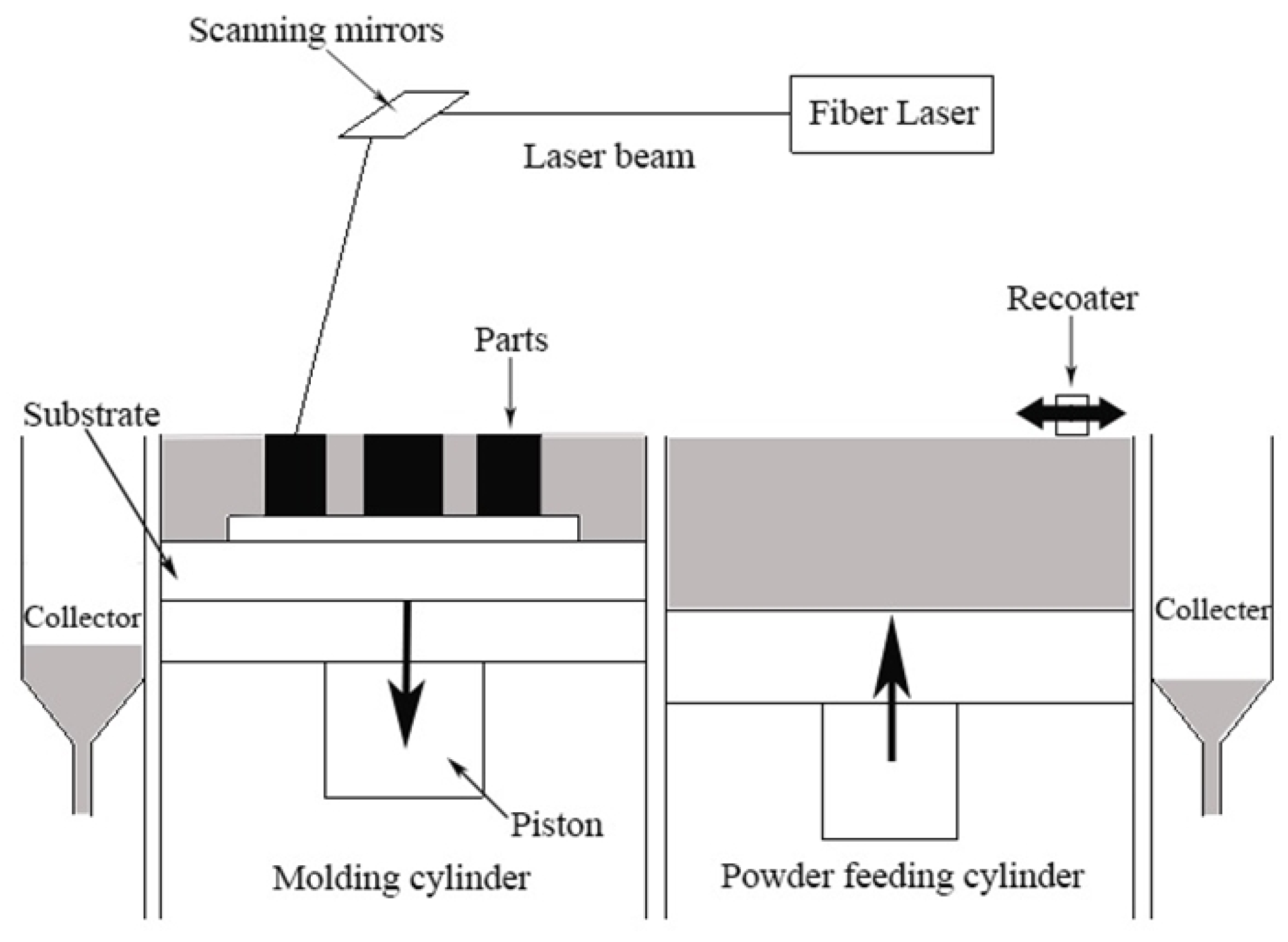
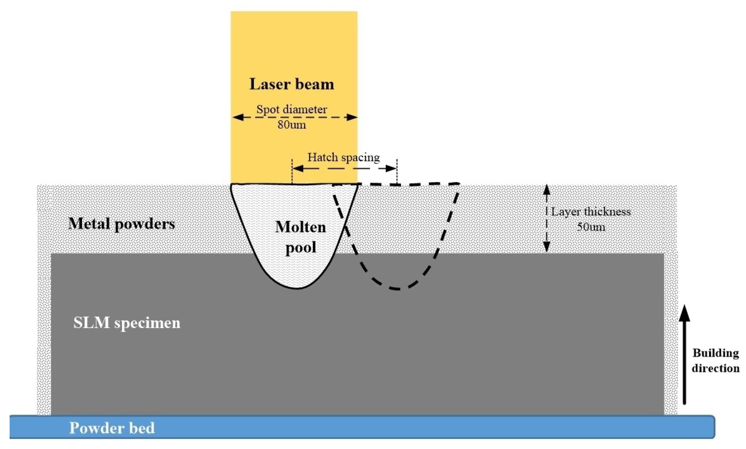
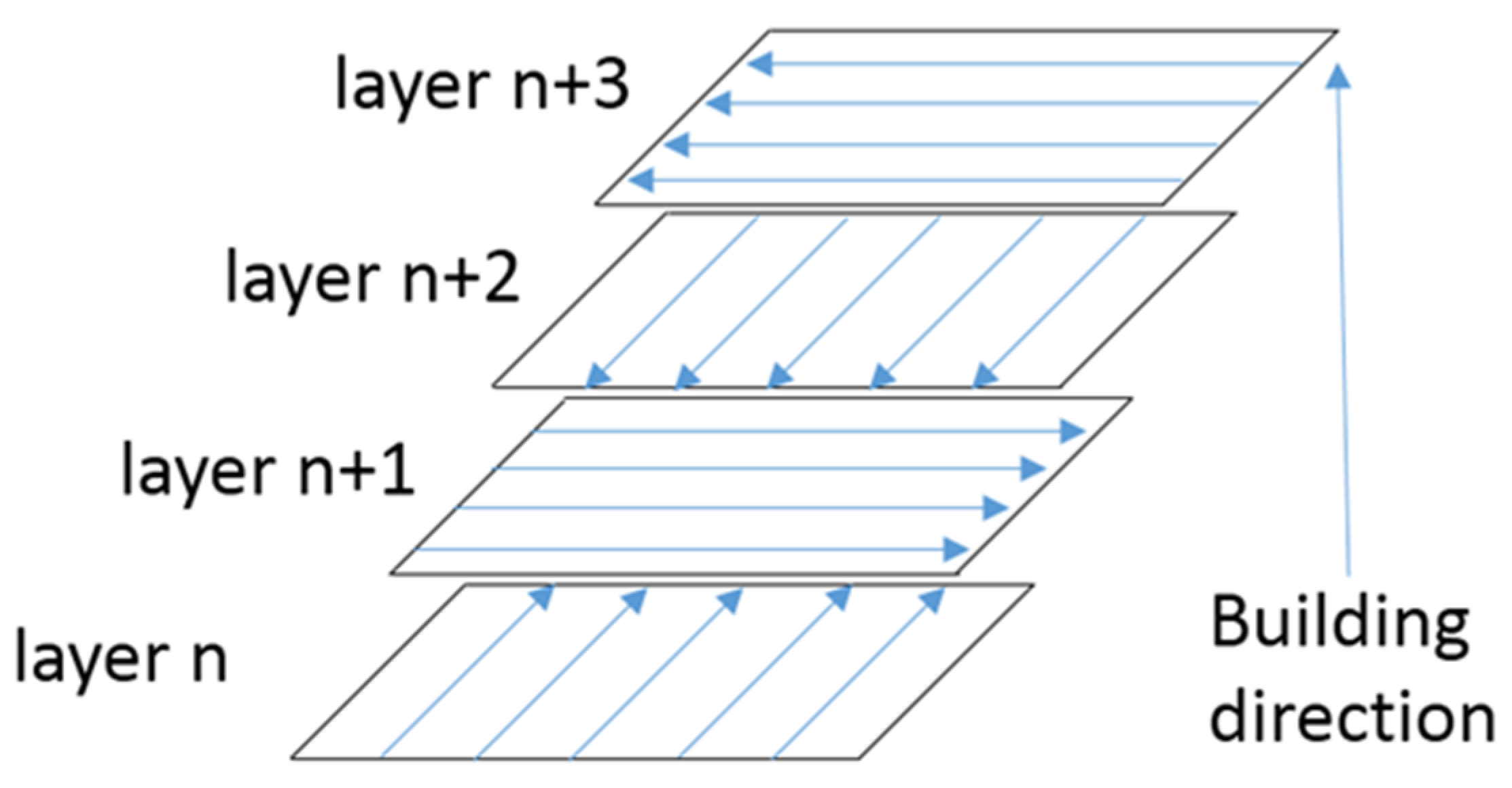
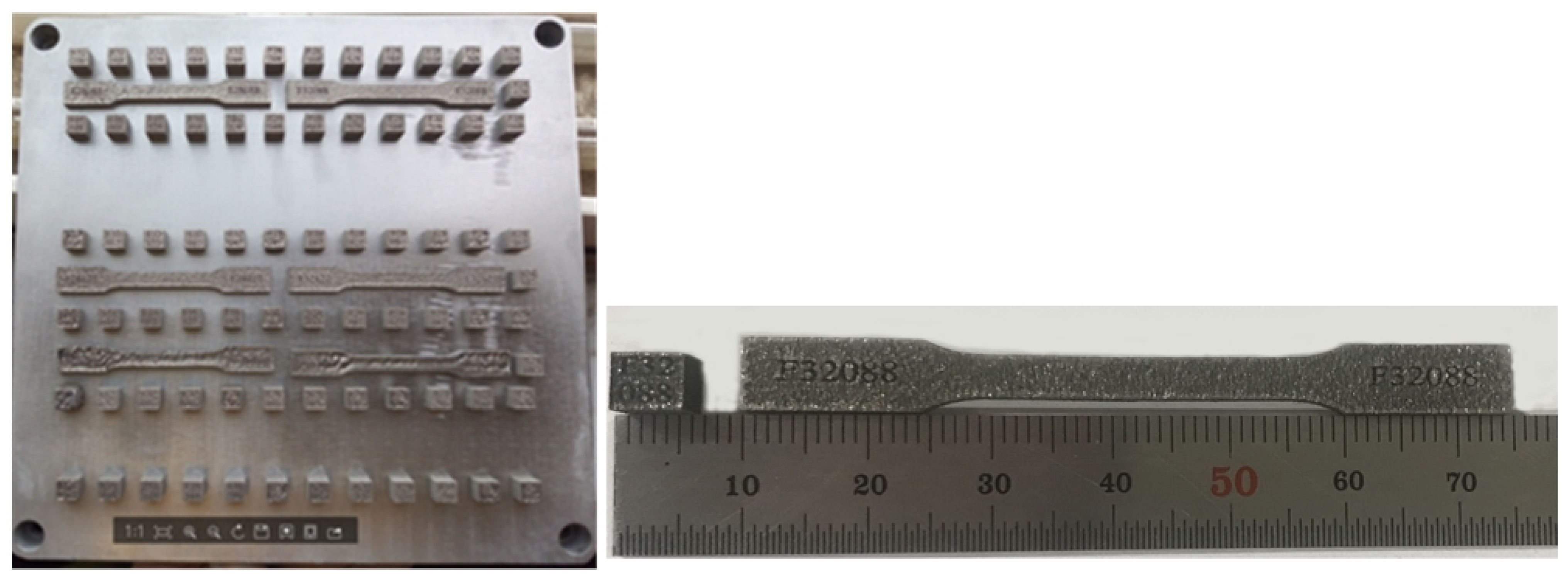
2.1. Experimental Materials and Procedures

In this study, the pre-mixed powders of a near-equimolar nominal composition of Al0.5CoCrFeNi with highly pure Al, Co, Cr, Fe, and Ni elements (99.99%, 37–74 μm) were used. These metal powders were homogenized using a XH-2-type three-dimensional mixing machine for 24 h under an argon atmosphere and then dried in a vacuum oven at a temperature of 100 °C for 10 h. Figure 1 shows the morphology of the elemental and mixed powders. Fe, Co, and Ni exhibited a spherical shape, Al was near spherical, and Cr showed an irregular, crushed shape.
All specimens were fabricated by the Xi’an Jiaotong University Rapid Prototyping (XJRP) SLM molding machine (as illustrated in Figure 2). The machine mainly consists of an500W fiber laser, PLC control system, inert argon gas protection and cooling system, powder layering device, three-dimensional workstations, and other components. The machine is controlled by the computer system using the rapid prototyping built (RPB) software programmed by Xi’an Jiaotong University, Xi’an, China. A laser beam with a spot size of 80 μm was used to scan the powder layer selected with a 50 μm thickness, according to the powder size, and is illustrated in Figure 3. During processing, the chamber is sealed and constantly kept in an argon atmosphere to maintain the oxygen concentration less than 10 ppm. An “orthogonal scanning strategy”, as shown in Figure 4, was adopted to fabricate all specimens. The SLM process parameters selected in this work are shown in Table 1.

2.2. Measurement of Microstructure and Mechanical Properties of Alloy

The 6 mm × 6 mm × 6 mm cubic specimens (as shown in Figure 5) were fabricated by varying the laser power, scanning speed, and hatch spacing according to Table 1. Density of the SLM specimens after fabrication was immediately measured by the Archimedes method. Then, the specimens were rinsed using ethanol in an ultrasonic cleaning bath (50 kHz, output power 150 W). After that, the specimens were prepared by grinding on a series of silicon carbide paper with 400, 600, 800, and 1000 grit, respectively, and lapping with a diamond polishing agent. Microstructures were characterized using scanning electron microscopy (SEM, JEOL JSM-6390A, Tokyo, Japan) equipped with an energy dispersive spectrometer (EDS). The crystal structure of the HEAs was analyzed by x-ray diffractometer (XRD, Bruker D8 Advance, Karlsruhe, Germany) with Cu Kα radiation operating at 40 kV/20 mA at a scanning speed of 4°/min from 2θ = 20°~100°. The hardness of the specimen was measured with a micro Vickers-hardness tester (Bahens HXD-1000TMC, Shanghai, China) under a load of 50 g and a dwelling time of 10 s. Tensile tests were carried out on a computer-controlled electronic universal mechanical testing machine with a loading rate of 1 mm/min. The tensile specimen was prepared directly from the rapid prototyping and the specimen size (Figure 5) was designed according to China national standard for metallic materials tensile testing at ambient temperature (GBT228-2002, Beijing, China) [15].

3. Results and Discussion

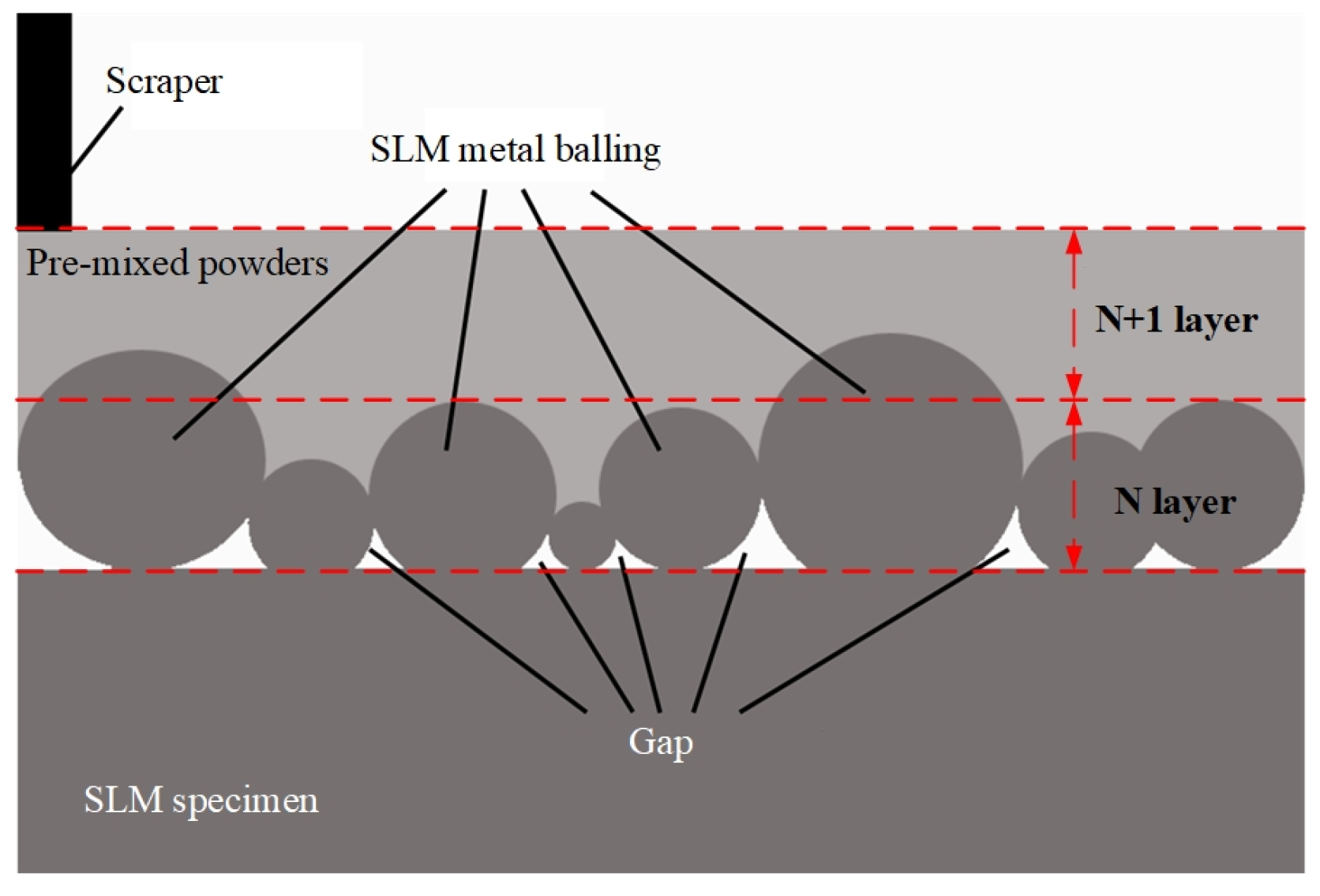
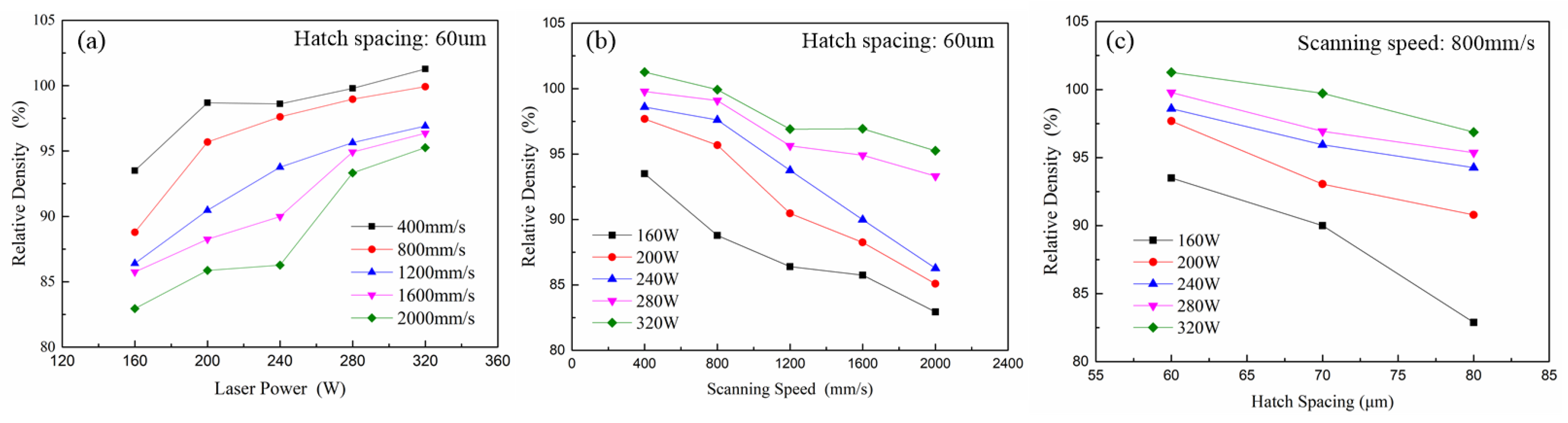
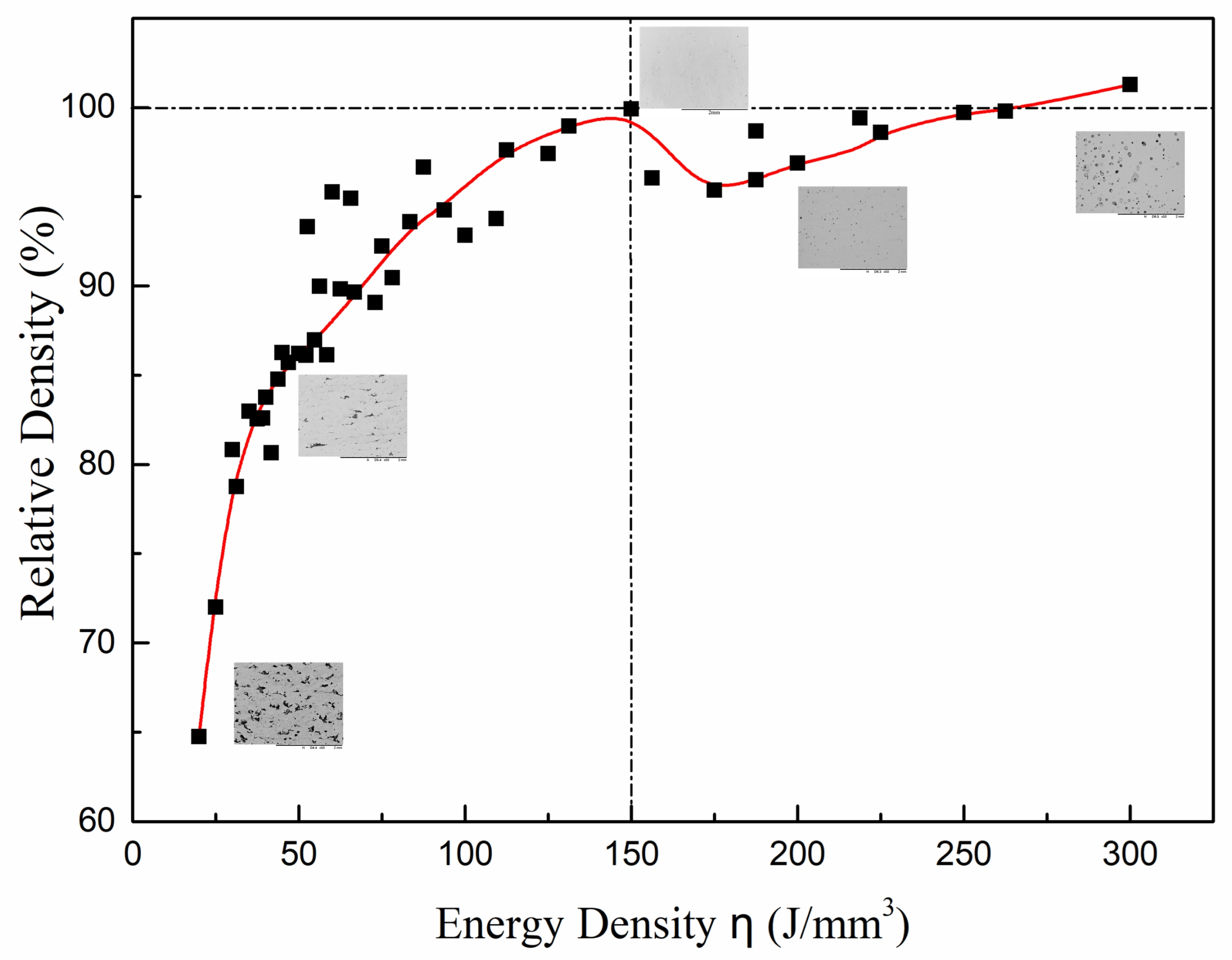
3.1. Optimization of the SLM Process Parameters

During SLM processing, the original metal powders were melted with absorbing laser energy, then solidified for forming. The laser power determines the amount of energy radiated per unit area of laser, which affects the temperature of the melt pool and density of samples [16]. Figure 6 shows the SEM morphologies of the Al0.5CoCrFeNi HEAs with different laser power at a scanning speed of 800 mm/s and hatch spacing of 60 μm. At a lower laser power (<200 W), it can be found that there were many cracks and pores, as shown in Figure 6a,b, which were partially caused by unmelted powder particles. In this case, the temperature of the melt pool was lower and the molten flow was not sufficient to generate the harsh balling phenomenon in the surface layer of powder bed [17]. The balling phenomenon, as an unfavorable defect due to using a low laser power during SLM processing, is a complex physical metallurgical process that is characterized by a highly coarsened and interrupted balling structure in the surface layer of the SLM specimen. The balling effect is discussed in detail in [17]. When the next layer builds (as shown in Figure 7), the gaps among the balling are difficult to fill with the melted alloys, and consequently are kept in the SLM specimens as pores. Meanwhile, the laser irradiation energy absorbed by the powders decreased due to the balling phenomenon. Consequently, the temperature of the melt pool decreased, and the size of the melt pool became small. This may have caused many pores containing the unmelted powder to form in the samples (presented in Figure 6b). It can be observed from Figure 6c,d that the number of cracks and non-melting particles decreased with increasing laser power. As the laser power reached 320 W, there were no cracks and unmelted visible powder particles found in the samples, as shown in Figure 6e. The forescatter electron detector (FSD) image and corresponding elemental distribution in Figure 6f indicate that the elemental distribution was basically uniform. This implies that within the power range considered in this study, increasing laser power is an effective approach to increase the temperature of the melt pool, and prevent the balling phenomenon of HEAs [18].
The influence of the process parameters including laser power, scanning speed, and hatch spacing on the densification of Al0.5CoCrFeNi HEAs was also investigated. If we define the relative density as R = ρ / ρ 0 , where ρ is the specimen density and ρ 0 is the theoretical density of 7.6 g/mm3, then the relationship between the process parameters and the relative density of Al0.5CoCrFeNi HEAs are presented as in Figure 8. It can be found from Figure 8a that the larger the laser power, the larger the relative density; and the density increasing trend was roughly consistent under different scanning speeds. This is also consistent with the observation of the morphologies of the Al0.5CoCrFeNi HEAs in Figure 6. On the other hand, the hatch spacing and scanning speed also affect the scanning overlap and the dwelling time of the laser beam on powders. The dwelling time of the laser beam on the powders was equal to the value of the laser spot diameter divided by scanning speed. The dwelling time decreased as the scanning speed increased. Correspondingly, the heat accumulation quantity in the powders and the temperature of the molten pool decreased. At the same time, the flow of molten metal was not sufficient. Therefore, it can be seen from Figure 8b,c that the relative density of the samples decreased with the increase in the hatch spacing and the scanning speed.
The combined effect of laser power, scanning speed, and hatch spacing on the energy density η (J/mm3) can be described as [19]
η = p ( 1 + d l d × 2 ) v × h × d ,   l d 2
where p is the laser power (W); v is the scanning speed (mm/s); l is the hatch spacing (μm); the laser spot diameter d is 80 μm; and the layer thickness h is 50 μm. The relationship between the energy density and the relative density of the samples can be obtained as shown in Figure 9, where the energy density was calculated from the data in Table 1. It can be seen from Figure 9 that the relative density monotonically increased at the range η < 150 J/mm3, the relative density decreased at the range of η = 150–180 J/mm3, and the relative density increased again as the energy density η > 180 J/mm3. Generally speaking, at the range η < 150 J/mm3, powders can be more easily melted with the increase in energy density, and the metallic liquid in the molten pool also becomes sufficient to fill into the gaps between powders, thus the relative density of the SLM specimens monotonically increased. When the energy density is in the range of η = 150–180 J/mm3, the relative density decreases significantly with the increase in energy density. This is because excessive laser irradiation energy input would lead to the high evaporation rate of the low melting point element Al, and the gasified Al elements do not have enough time to evaporate from the molten pool during the solidification process. As a result, many pores are formed in the solidified SLM specimen and its relative density decreased [13]. It can also be seen from Figure 9 that the relative density increased again at the range η > 180 J/mm3. At the same time, it can be observed from Figure 9 that when the energy density reached η = 250–300 J/mm3, the relative density could be greater than 1. Table 2 shows the chemical composition of the SLM specimen under different energy densities. The concentration of Al was only 10.03% less than the nominal composition when the energy density η = 300 J/mm3. This deviates from the designed Al0.5CoCrFeNi HEAs. Therefore, the main reason for a specimen density greater than the theoretical density is that the over-burning and evaporation of the Al element with a low melting point leads to a relative increase in the heavy elements of the entire specimen. Therefore, it can be concluded from Figure 9 that an energy density of approximately 150 J/mm3 is able to ensure high relative density and at the same time avoid over-burning of the Al element. The corresponding optimized fabricating parameters such as the laser power, the scanning speed, and the hatch spacing were specified as 320 W, 800 mm/s, and 60 μm, respectively, and the corresponding relative density was about 99.92%.

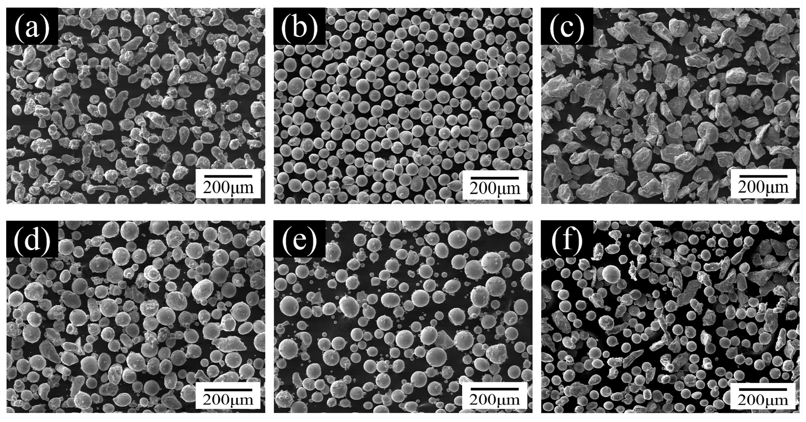
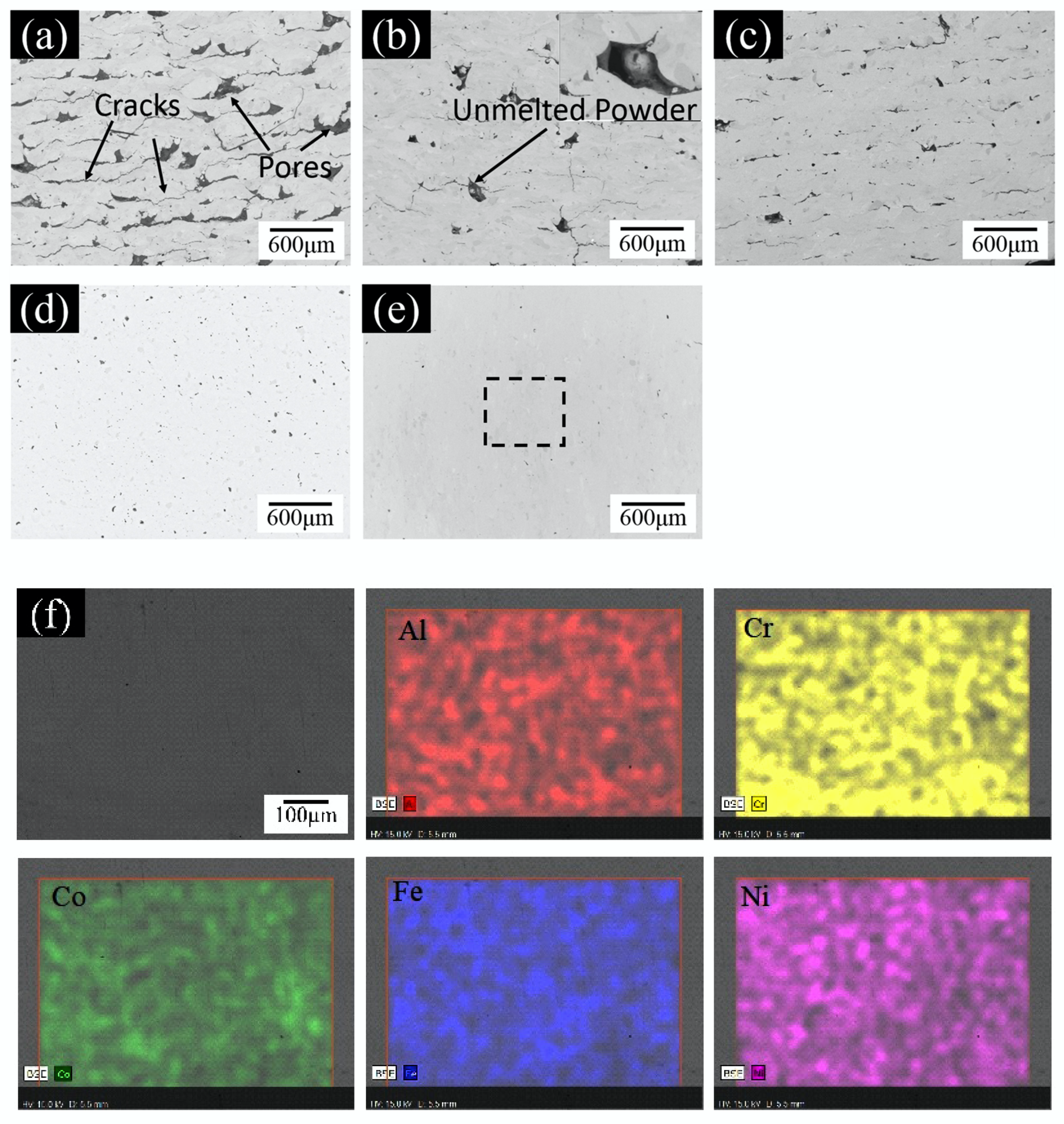
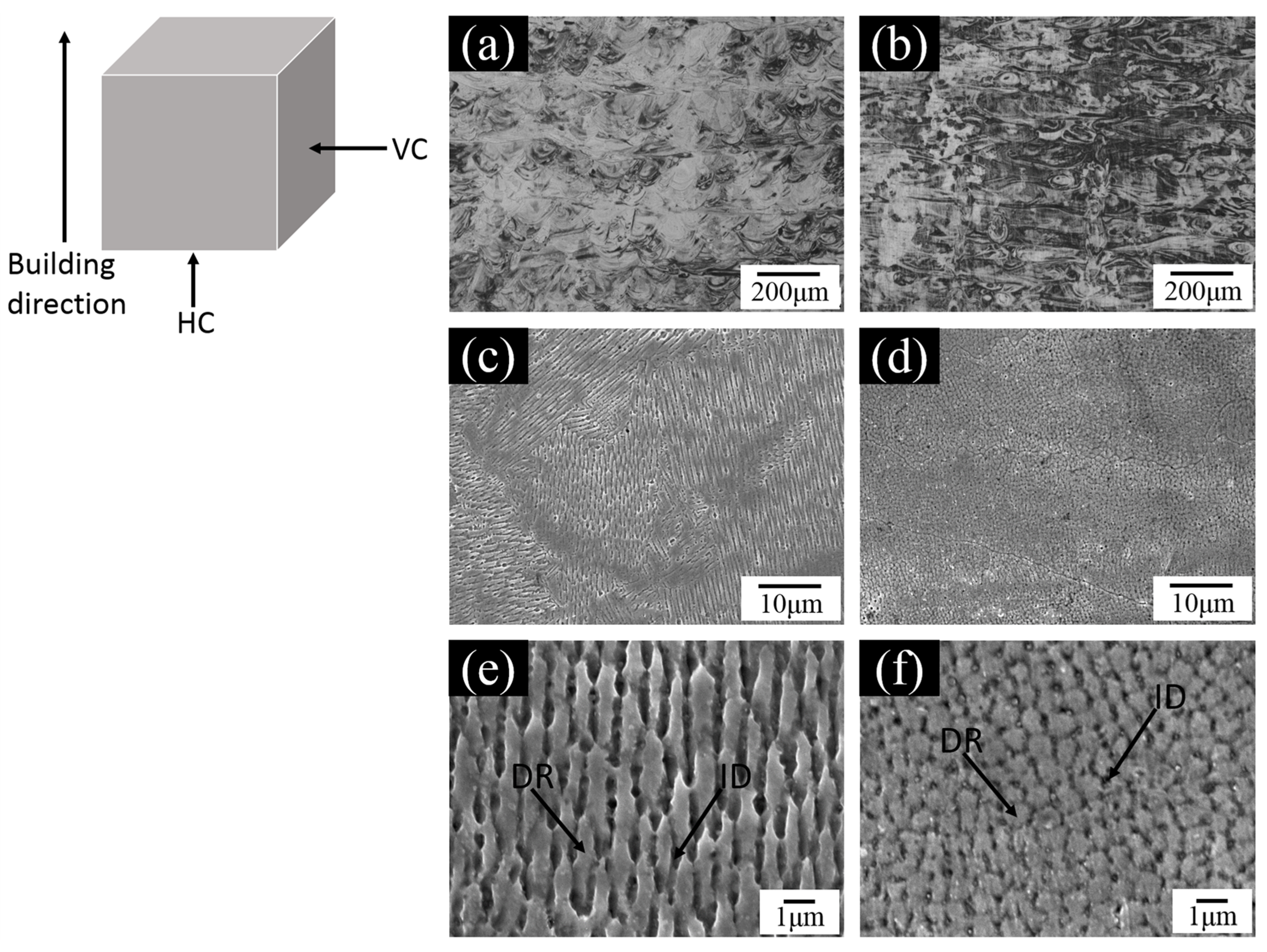
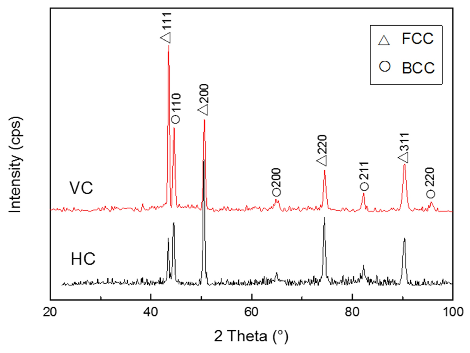
3.2. Microstructures of Al0.5CoCrFeNi HEAs

The Al0.5CoCrFeNi HEAs specimen was fabricated by SLM with the optimized parameters as described above. The structure observation positions are the vertical and horizontal cross sections of the SLM specimen. Figure 10a,b show the optical micrographs of the vertical cross section (VC) and horizontal cross section (HC) of the SLM specimens. The layers, with semi-circular shape structures that are 80 μm in width, similar to the laser spot diameter observed, were equal in thickness to the powder layer thickness of 50 μm in the vertical cross sections. These are scattered at a layer-thickness distance due to the orthogonal scanning strategy. In fact, the semi-circular structures of Gaussian surface distribution are the laser scanning tracks due to the energy input during the laser scanning process [20]. In the vertical cross sections, the microstructures observed were ellipsoid. Figure 10c–f show the microstructure SEM images in the vertical and horizontal cross sections. The columnar structure, exhibiting a typical epitaxial growth perpendicular to the laser scanning tracks (i.e., the direction of heat flow), were observed in the vertical cross section (see Figure 10c,e). In general, most of the heat induced by laser irradiation was transmitted through previous solidified materials. Fine cellular-dendritic structures around 1 μm in size were observed in the horizontal cross section (see Figure 10d,f). These fine columnar crystals formed in response to the rapid solidification and the large thermal gradient created by the large amount of energy used to melt thin layers of powder near the solid–liquid interface during SLM processing [7,21]. In general, the fine microstructures can promote excellent mechanical properties. Based on the SEM images shown in Figure 10 in combination with the EDS analysis in Table 3, it can be seen that the chemical composition of cellular-dendritic regions (DR) is the composition of the overall alloy, but there was evidence in inter-dendritic regions (ID). The ID in the SLM-processed Al0.5CoCrFeNi HEA were richer in Al and Ni than the DR. The atomic radius of the Al element was the largest relative to other elements, resulting in its lower solid solution in the solid solubility, so the Al element tends to segregate in the final solidification regions (ID), leading to the Al element being more easily segregated in an inter-dendritic structure [22]. Table 4 presents the values of enthalpy of mixing ( Δ H ( ab ) mix ) of the binary liquid in a bi-elements system at an equi-atomic composition in the Al0.5CoCrFeNi HEA system [23]. Rich phase Al–Ni has a higher negative mixing enthalpy than other atom pairs of the five principal elements. In practice, the negative mixing enthalpy of these particular atoms prevents the segregation of the Al–Ni rich phase in inter-dendritic regions [24].
Figure 11 shows the XRD analysis results of the vertical and horizontal cross sections of the SLM-processed Al0.5CoCrFeNi HEA. It can be found that the microstructure contains face-centered cubic (FCC) and body-centered cubic (BCC) phases, without complex intermetallic compounds, which is consistent with the HEAs obtained through traditional manufacturing processes [25,26]. The FCC phase exhibited the strongest peak (111) planes in the vertical cross section. However, the strongest peak of the XRD analysis results was in the (200) plane in the horizontal cross section. The difference in the strongest peak position between the vertical and horizontal cross sections means the different priority growth orientation of grains, which may lead to the different performances of materials in different directions, namely anisotropic.

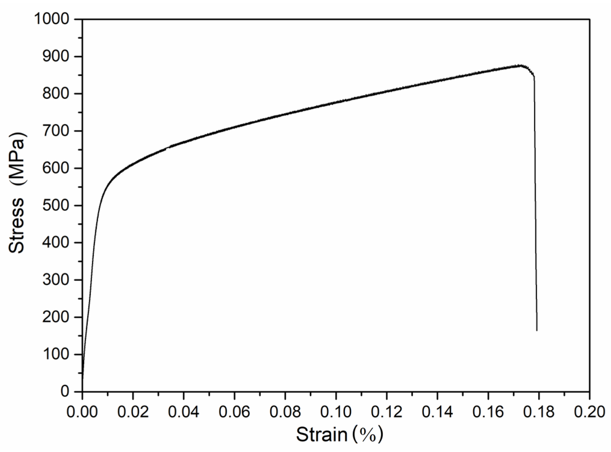
3.3. Mechanical Properties of Al0.5CoCrFeNi HEAs

The hardness of the HEAs fabricated under the vacuum arc melting (VAM) condition was about 180 HV [26], whilst the ones by SLM were, respectively, about 270 HV in the horizontal cross section and 245 HV in the vertical cross section. According to the analysis in the above section, the columnar cellular-dendritic structure size of the HEAs fabricated by SLM was about 1 μm, whilst the equiaxed grain size of the HEAs fabricated under the vacuumed induction melting condition was about 50 μm [27]. Thus, it can be deduced that the hardness enhancement can mainly be ascribed to the substructure size effect. Furthermore, it was found that the Vickers hardness of the horizontal cross sections was slightly higher than that of the vertical cross sections. This can be attributed to the anisotropy of the microstructure of the HEAs fabricated by SLM [27].
The tensile specimens of the Al0.5CoCrFeNi HEAs were prepared directly from the rapid prototyping with optimized SLM parameters without grinding and lapping, as shown in Figure 5. The uniaxial tensile stress–strain curve of the SLM specimen is presented in Figure 12. It can be found that the yield strength was about 609 MPa, the tensile strength was 878 MPa, and the elongation was 18%. Compared with the VAM sample [28], the tensile strength increased by 68% (522 MPa → 878 MPa), but the elongation decreased from 26.4% to 18%. In general, from the above analysis, it can be ascertained that the SLM fabrication approach is a promising one. Figure 13 show the SEM images of the fracture surface for the SLM-processed Al0.5CoCrFeNi HEAs at ambient temperature. Pores and unmelted powders in the fracture surface generally have a detrimental effect on the tensile properties (as seen in Figure 13a). Figure 13b shows that the presence of dimples that are flat and faceted gave rise to large cracks during failure, indicating that there was remarkable toughness fracture surface morphology [29,30]. Meanwhile, another image partly illustrates the characteristics of the quasi-cleavage fracture such as angular faceted steps and cleavage feathers [31].

4. Conclusions

In this paper, the selective laser melting (SLM) approach to fabricating Al0.5CoCrFeNi HEAs was studied. The influence of process parameters such as the laser power, the scanning speed, and the hatch spacing on the relative density was investigated. The microstructure and mechanical properties of the samples were also analyzed to obtain the optimized process parameters. The corresponding conclusions can be drawn from this study as follows:
(1) The Al0.5CoCrFeNi HEA sample with a relative density of 99.92% was achieved by optimizing the SLM process parameters with a laser power of 320 W, scanning speed of 800 mm/s, and hatch spacing of 60 μm, respectively.
(2) The microstructure of the SLM Al0.5CoCrFeNi HEA was a fine cellular-dendritic structure, without complex intermetallic compounds.
(3) Mechanical properties of the SLM Al0.5CoCrFeNi HEAs were significantly improved: the yield strength reached 609 MPa, and the tensile strength was 878 MPa, which increased by 68% (522 MPa → 878 MPa) when compared to the vacuum arc melting samples.
(4) It was demonstrated that the fabrication of HEAs by SLM with pre-mixed powders is feasible, which provides a new approach to prepare HEAs.

Author Contributions

K.S., and L.F., conceived and designed the experiments; K.S., W.P., and L.Y., performed the experiments; K.S., and W.P., analyzed the data; K.S., wrote the paper. All authors have read and agreed to the published version of the manuscript.

Funding

This research was funded by the National Natural Science Foundation of China (No. 51475359).

Conflicts of Interest

The authors declare no conflict of interest.

References

  1. Yeh, J.W.; Chen, S.K.; Lin, S.J.; Gan, J.Y.; Chin, T.S.; Shun, T.T.; Tsau, C.H.; Chang, S.Y. Nanostructured High-Entropy Alloys with Multiple Principal Elements: Novel Alloy Design Concepts and Outcomes. Adv. Eng. Mater. 2004, 6, 299–303. [Google Scholar] [CrossRef]
  2. Huang, P.; Yeh, J.W.; Shun, T.T.; Chen, S.K. Multi-Principal-Element Alloys with Improved Oxidation and Wear Resistance for Thermal Spray Coating. Adv. Eng. Mater. 2004, 6, 74–78. [Google Scholar] [CrossRef]
  3. Cantor, B.; Chang, T.H.; Knight, P.; Vincent, A.J.B. Microstructural Development in Equiatomic Multicomponent Alloys. Mater. Sci. Eng. A 2004, 375, 213–218. [Google Scholar] [CrossRef]
  4. Torralba, J.M.; Alvaredo, P.; García-Junceda, A. High-entropy alloys fabricated via powder metallurgy. A critical review. Powder Metall. 2019, 62, 84–114. [Google Scholar] [CrossRef]
  5. Gao, M.C.; Yeh, J.W.; Liaw, P.K.; Zhang, Y. High-Entropy Alloys; Springer: Basel, Switzerland, 2016. [Google Scholar]
  6. Gibson, I.; Rosen, D.; Stucker, B. Additive Manufacturing Technologies; Springer: Basel, Switzerland, 2010. [Google Scholar]
  7. Kimura, T.; Nakamoto, T. Microstructures and Mechanical Properties of A356 (AlSi7Mg0.3) Aluminum Alloy Fabricated by Selective Laser Melting. Mater. Des. 2016, 89, 1294–1301. [Google Scholar] [CrossRef]
  8. Sames, W.J.; List, F.A.; Pannala, S.; Dehoff, R.R.; Babu, S.S. The Metallurgy and Processing Science of Metal Additive Manufacturing. Int. Mater. Rev. 2016, 61, 1–46. [Google Scholar] [CrossRef]
  9. Zinovieva, O.; Zinoviev, A.; Ploshikhin, V. Three-dimensional modeling of the microstructure evolution during metal additive manufacturing. Comput. Mater. Sci. 2018, 141, 207–220. [Google Scholar] [CrossRef]
  10. Ocelík, V.; Janssen, N.; Smith, S.N.; De Hosson, J.T.M. Additive Manufacturing of High-Entropy Alloys by Laser Processing. Jom 2016, 68, 1810–1818. [Google Scholar] [CrossRef] [Green Version]
  11. Joseph, J.; Jarvis, T.; Wu, X.; Stanford, N.; Hodgson, P.; Fabijanic, D.M. Comparative Study of the Microstructures and Mechanical Properties of Direct Laser Fabricated and Arc-melted AlxCoCrFeNi High Entropy Alloys. Mater. Sci. Eng. A 2015, 633, 184–193. [Google Scholar] [CrossRef]
  12. Dobbelstein, H.; Thiele, M.; Gurevich, E.L.; George, E.P.; Ostendorf, A. Direct Metal Deposition of Refractory High Entropy Alloy MoNbTaW. Phys. Procedia 2016, 83, 624–633. [Google Scholar] [CrossRef] [Green Version]
  13. Brif, Y.; Thomas, M.; Todd, I. The Use of High-entropy Alloys in Additive Manufacturing. Scr. Mater. 2015, 99, 93–96. [Google Scholar] [CrossRef]
  14. Zhu, Z.G.; Nguyen, Q.B.; Ng, F.L.; An, X.H.; Liao, X.Z.; Liaw, P.K.; Nai, S.M.L.; Wei, J. Hierarchical Microstructure and Strengthening Mechanisms of a CoCrFeNiMn High Entropy Alloy Additively Manufactured by Selective Laser Melting. Scr. Mater. 2018, 154, 20–24. [Google Scholar] [CrossRef]
  15. Liang, X.; Li, J.; Tao, L. Metallic Materials Tensile Testing at Ambient Temperature, National Standards of P.R.C.; General Administration of Quality Supervision, Inspection and Quarantine of the People’s Republic of China: Beijing, China, 2002. (In Chinese)
  16. Read, N.; Wang, W.; Essa, K.; Attallah, M.M. Selective Laser Melting of AlSi10Mg Alloy: Process Optimisation and Mechanical Properties Development. Mater. Des. 2015, 65, 417–424. [Google Scholar] [CrossRef] [Green Version]
  17. Brandt, M. Laser Additive Manufacturing: Materials, Design, Technologies, and Applications; Woodhead Publishing: Cambridge, UK, 2017. [Google Scholar]
  18. Gu, D.; Shen, Y. Balling Phenomena in Direct Laser Sintering of Stainless Steel Powder: Metallurgical Mechanisms and Control Methods. Mater. Des. 2009, 30, 2903–2910. [Google Scholar] [CrossRef]
  19. Gu, H.; Gong, H.; Pal, D.; Rafi, K.; Starr, T.; Stucker, B. Influences of Energy Density on Porosity and Microstructure of Selective Laser Melted 17-4PH Stainless Steel. In Proceedings of the 2013 Solid Freeform Fabrication Symposium, Austin, TX, USA, 12 August 2013. [Google Scholar]
  20. Tolochko, N.K.; Mozzharov, S.E.; Yadroitsev, I.A.; Laoui, T.; Froyen, L.; Titov, V.I.; Ignatiev, M.B. Balling Processes During Selective Laser Treatment of Powders. Rapid Prototyp. J. 2004, 10, 78–87. [Google Scholar] [CrossRef]
  21. Amato, K.N.; Gaytan, S.M.; Murr, L.E.; Martinez, E.; Shindo, P.W.; Hernandez, J.; Collins, S.; Medina, F. Microstructures and Mechanical Behavior of Inconel 718 Fabricated by Selective Laser Melting. Acta Mater. 2012, 60, 2229–2239. [Google Scholar] [CrossRef]
  22. Gao, Y.M. The Principle of Metal Solidification; Xi’an Jiaotong University Press: Xi’an, China, 2010. (In Chinese) [Google Scholar]
  23. Takeuchi, A.; Inoue, A. Classification of Bulk Metallic Glasses by Atomic Size Difference, Heat of Mixing and Period of Constituent Elements and Its Application to Characterization of the Main Alloying Element. Mater. Trans. 2005, 46, 2817–2829. [Google Scholar] [CrossRef] [Green Version]
  24. Tsai, C.W.; Chen, Y.L.; Tsai, M.H.; Yeh, J.W.; Shun, T.T.; Chen, S.K. Deformation and Annealing Behaviors of High-entropy Alloy Al0.5CoCrCuFeNi. J. Alloys Compd. 2009, 486, 427–435. [Google Scholar] [CrossRef]
  25. Zhang, Y.; Li, J.; Wang, J.; Niu, S.; Kou, H. Hot Deformation Behavior of As-Cast and Homogenized Al0.5CoCrFeNi High Entropy Alloys. Metals 2016, 6, 277. [Google Scholar] [CrossRef] [Green Version]
  26. Wang, W.R.; Wang, W.L.; Yeh, J.W. Phases, Microstructure and Mechanical Properties of AlxCoCrFeNi High-entropy Alloys at Elevated Temperatures. J. Alloys Compd. 2014, 589, 143–152. [Google Scholar] [CrossRef]
  27. Jiao, Z.M.; Chu, M.Y.; Yang, H.J.; Wang, Z.H.; Qiao, J.W. Nanoindentation Characterised Plastic Deformation of a Al0.5CoCrFeNi High Entropy Alloy. Mater. Sci. Technol. 2015, 31, 174. [Google Scholar] [CrossRef]
  28. Tang, Q.H.; Zhao, Y.G.; Cai, J.B. Effect of Aging Treatment on Microstructures and Mechanical Properties of Al0.5CoCrFeNi High-entropy Alloy. Mater. Sci. 2015, 13, 47–50. (In Chinese) [Google Scholar]
  29. Louvis, E.; Fox, P.; Sutcliffe, C.J. Selective Laser Melting of Aluminium Components. J. Mater. Process. Technol. 2011, 211, 275–284. [Google Scholar] [CrossRef]
  30. Hertzberg, R.W. Deformation and Fracture Mechanics of Engineering Materials. J. Eng. Mater. Technol. 1977, 99, 96. [Google Scholar] [CrossRef] [Green Version]
  31. Senkov, O.N.; Wilks, G.B.; Scott, J.M.; Miracle, D.B. Mechanical Properties of Nb25Mo25Ta25W25, and V20Nb20Mo 20Ta20W20, Refractory High Entropy Alloys. Intermetallics 2011, 19, 698–706. [Google Scholar] [CrossRef]
Figure 1. SEM micrograph of the powders: (a) Al, (b) Co, (c) Cr, (d) Fe, (e) Ni, and (f) mixed.
Metals 10 00292 g001
Figure 2. The schematic illustration of the XJRP SLM molding machine.
Metals 10 00292 g002
Figure 3. Schematic illustration of the SLM processing parameters.
Metals 10 00292 g003
Figure 4. Schematic illustration of the laser scanning pattern: “orthogonal scanning strategy”.
Metals 10 00292 g004
Figure 5. Photograph of the SLM-processed sample and tensile specimen.
Metals 10 00292 g005
Figure 6. The SEM images of Al0.5CoCrFeNi HEAs at different laser power: (a) 160 W, (b) 200 W, (c) 240 W, (d) 280 W, (e) 320 W at a scan speed of 800 mm/s and hatch spacing of 60 μm, and (f) image of the selected area illustrated by a square in (e) and the elemental distribution maps of the area.
Metals 10 00292 g006
Figure 7. Schematic illustration of the balling effect during SLM processing.
Metals 10 00292 g007
Figure 8. The influence of the process parameters on the relative density of the SLM specimens: (a) laser power, (b) scanning speed, and (c) hatch spacing.
Metals 10 00292 g008
Figure 9. The relationship between energy density and relative density of the SLM specimens.
Metals 10 00292 g009
Figure 10. The micrographs of the specimens fabricated by SLM with the optimized parameters: the vertical cross (VC) sections (a), (c), and (e) and the horizontal cross (HC) sections (b), (d), and (f).
Metals 10 00292 g010
Figure 11. XRD patterns of the cross sections of the Al0.5CoCrFeNi HEAs.
Metals 10 00292 g011
Figure 12. The uniaxial tensile stress–strain curve of the SLM Al0.5CoCrFeNi HEAs.
Metals 10 00292 g012
Figure 13. The SEM images of the fracture surface for the SLM specimen at room temperature: (a) low magnifications, (b) high magnifications.
Metals 10 00292 g013
Table 1. The list of SLM processing parameters.
layer thickness (μm)50
Laser power (W)160~320
Scanning speed (mm/s)400~2000
Hatch spacing (μm)60~80
Table 2. Chemical composition of the SLM samples under different energy densities (at.%).
η/J·mm−3AlCoCrFeNi
Nominal11.1122.2222.2222.2222.22
5011.3422.8922.0122.8020.96
15011.0021.5622.6522.8619.37
30010.0322.4522.4822.4122.63
Table 3. Chemical composition of the SLM specimens (at.%).
MicrostructureAlCoCrFeNi
Nominal11.1122.2222.2222.2222.22
DR9.2524.4623.7423.1819.37
IR22.2714.0511.5817.3534.75
Table 4. The mixing enthalpy Δ H ( ab ) mix of atom pairs in the Al0.5CoCrFeNi HEAs (kJ/mol) [23].
ElementsAlCoCrFeNi
Al0−19−10−11−22
Co-0−4−1/
Cr--0−1−7
Fe---0−2
Ni----0

