Article

The Elusive Thomson Effect in Thermoelectric Devices. Experimental Investigation from 363 K to 213 K on Various Peltier Modules

Energy Department Politecnico di Torino, 24 Corso Duca degli Abruzzi, 10129 Turin, Italy
*
Author to whom correspondence should be addressed.
Metals 2020, 10(2), 291; https://doi.org/10.3390/met10020291
Submission received: 30 January 2020 / Revised: 18 February 2020 / Accepted: 20 February 2020 / Published: 23 February 2020
(This article belongs to the Special Issue Thermoelectric Compounds: Processing, Properties and Applications)

Abstract

:
At steady state, in the governing equation of one-stage thermoelectric cooler, the heat resulting from Fourier conduction is balanced by heat generation due to the Joule and Thomson effects inside semiconductors. Since the heat flux observed at the junction of a semiconductor, r pair includes the Peltier effect and the Fourier heat flux caused by both the aforementioned contributions, the Thomson effect is easily masked by the Joule heat, which makes it elusive. With the aim of highlighting the contribution of the Thomson effect, measurements were carried out in the temperature range from 363 K to 213 K on different Peltier modules. The temperature dependence of the Seebeck and Thomson coefficients was evaluated as well as the electrical resistivity, and thermal conductivity of the Peltier modules examined. The results obtained show that the temperature dependence of the thermoelectric properties can reduce the cooling capacity of the Peltier module compared to what is declared in the technical datasheets of the commercial devices. The analyses allow us to conclude that an increase in the Thomson effect could have a positive effect on the performance of the Peltier only if it were possible to reduce the Joule contribution simultaneously.

1. Introduction

There are many technological areas in which wasted energy can be successfully harvested by thermoelectric devices, such as residential building, automotive sector, and also railway rolling stock [1,2,3]. Moreover, the thermoelectric coolers meet many opportunities in the refrigeration of electronic systems [4,5,6], and in several laboratory applications, these devices can represent the optimal solution to achieve low temperatures without using a refrigerant medium, since they are compact, have no moving parts and vibrations, and are typically highly reliable. For example, to obtain low and stable thermal levels for mimicking the effects induced on the biological tissue by a surgical cryoprobe, single-stage Peltier devices have been assembled in a stack, by feeding each one with proper electrical currents [7,8]. In the latter, the well-known complaint about the poor performance of these devices is of little importance, but the relationship between the feeding current, the cooling capacity, and the minimum temperature reached must be adequately known. With this aim, some different experimental procedures can be found in the literature [6,9,10]. Although few of these suggest alternative methods on determining the thermoelectric properties, the Thomson effect is commonly not considered in the theoretical approach.
More in general, in order to use Peltier devices at thermal levels far from ambient conditions, adequate characterization of the thermoelectric properties involved is required at different temperatures. An advantage of this analysis is the knowledge of the temperature dependence of the Seebeck coefficient, so the typically eluded Thomson effect can be considered properly. If on the one hand, the Thomson effect makes less obvious the link between the cooling capacity and the temperature difference between the junctions at a given feeding current, on the other hand, highlighting the role of this thermoelectric effect is useful to understand its impact on the performance of thermoelectric devices.
In recent decades several Authors have paid attention to the Thomson effect considering its influence on the performance of a thermoelectric generator [11] and cooler [12,13,14,15], also under transient conditions [16]. For these Authors, a common conclusion regards the possible benefit on the device performance that can be introduced by Thomson heat. They also indicate that the “bottleneck” is due to the capability of the material, which can be resolved by optimizing the temperature dependence of the Seebeck coefficient [17]. Along this path, an interesting theoretical work [18] suggests that a thermoelectric cooler can be designed to achieve the full thermoelectric compatibility, thanks to which the Thomson effect plays an important role in reaching very low temperature even if the figure of merit is low. Moreover, many thermoelectric materials are being explored for power generation applications, such as silicides [19], PbTe [20], half-Heusler alloys [21], and skutterudites [22], in which Thomson effect can occur and improve the device performances. But, nowadays, the so-called "commercial devices" are typically not designed to follow these criteria.
This paper presents the experimental investigations carried out on various commercial Peltier modules over their whole operating temperature range. The thermal characterization of these devices was performed by measuring the figure of merit and the electrical resistance of each module [23,24]. Moreover, the temperature on the hot and cold sides was measured on a few selected modules, and equivalent values of some properties were calculated: the Seebeck coefficient, electrical resistivity, and thermal conductivity of the thermoelectric materials with which modules are built. The analysis of the results made it possible to put in evidence the Thomson effect intrinsic to the semiconductor materials that constitute the investigated modules. The comparison between the thermoelectric effects that occur inside these materials has shown that the Joule effect is dominant on the performance of such modules and that the temperature dependence of both electrical resistivity and thermal conductivity seems more important than the Thomson effect that takes place in the semiconductors employed.

2. Materials and Experimental Methods

The Peltier modules investigated are single-stage, marketed under different brands, manufactured with a p-n series of Bismuth Telluride semiconductor material ( B i 2 T e 3 ), and assembled between plates made of ceramic stuff that can be assumed as A l 2 O 3 . The number of pairs and some geometric features of these modules, are shown in Table 1, assuming for all devices, the semiconductor pillars as parallelepipeds with a square base.
The geometric dimensions shown in Table 1 were obtained using a caliper, measuring the thickness of the whole module, the thickness of the ceramic plate, and the size of the pillars (height and base side). The agreement between the measured dimensions of the pillars and the dimensions of the whole module (height L and width W) was verified by evaluating with a blade gauge the gap between the pillars and the thickness of the connecting copper elements to which the p-n semiconductors are soldered to form the junctions. The filling factor, reported in the last column of Table 1, is the ratio between the sum of the cross-sections of all the semiconductor elements and the entire surface area of the ceramic plates. The filling factor can be useful to take into account the spreading-constriction thermal resistance between pillars and ceramic plates.
The modules named a.1, a.2, and a.3 have the same number of pairs, with some differences in the total thickness and size of the pillar, but quite a similar filling factor and assembly features. Therefore, based on the performances declared by the manufacturer, similar values of the figure of merit were expected for these three modules. Modules b and c are totally different from each other and from the previous ones, in particular as regards the dimensions of the pillar, the filling factor, and assembly characteristics; therefore, for the latter, rather different figures of merits are foreseen.
As known, the dimensionless figure of merit zT can be evaluated in a real device by measuring the electrical quantities at the accessible external connections, since it can be obtained as the ratio between the total developed Seebeck voltage and the total ohmic voltage drop. Separating the two contributions is not trivial and is traditionally performed with a time-domain transient approach called the “Harman method” [23]. The idea behind the method is that when a dc current, which flows through the device, is switched off, the sudden voltage drop experienced at the device terminals is due to the ohmic voltage that disappears with the current, while the thermoelectric voltage persists due to the thermal inertia of the device, which prevents fast temperature variations. Based on this criterion, the figure of merit and the ohmic series resistance of the tested thermoelectric modules were measured using a commercial time-domain Harman type instrument [25] produced by RMT (Moscow, Russia), named z-meter model DX 4090. The DX 4090 instrument also estimates the characteristic time and the maximum temperature difference that can be reached between the junctions of the Peltier device under test.
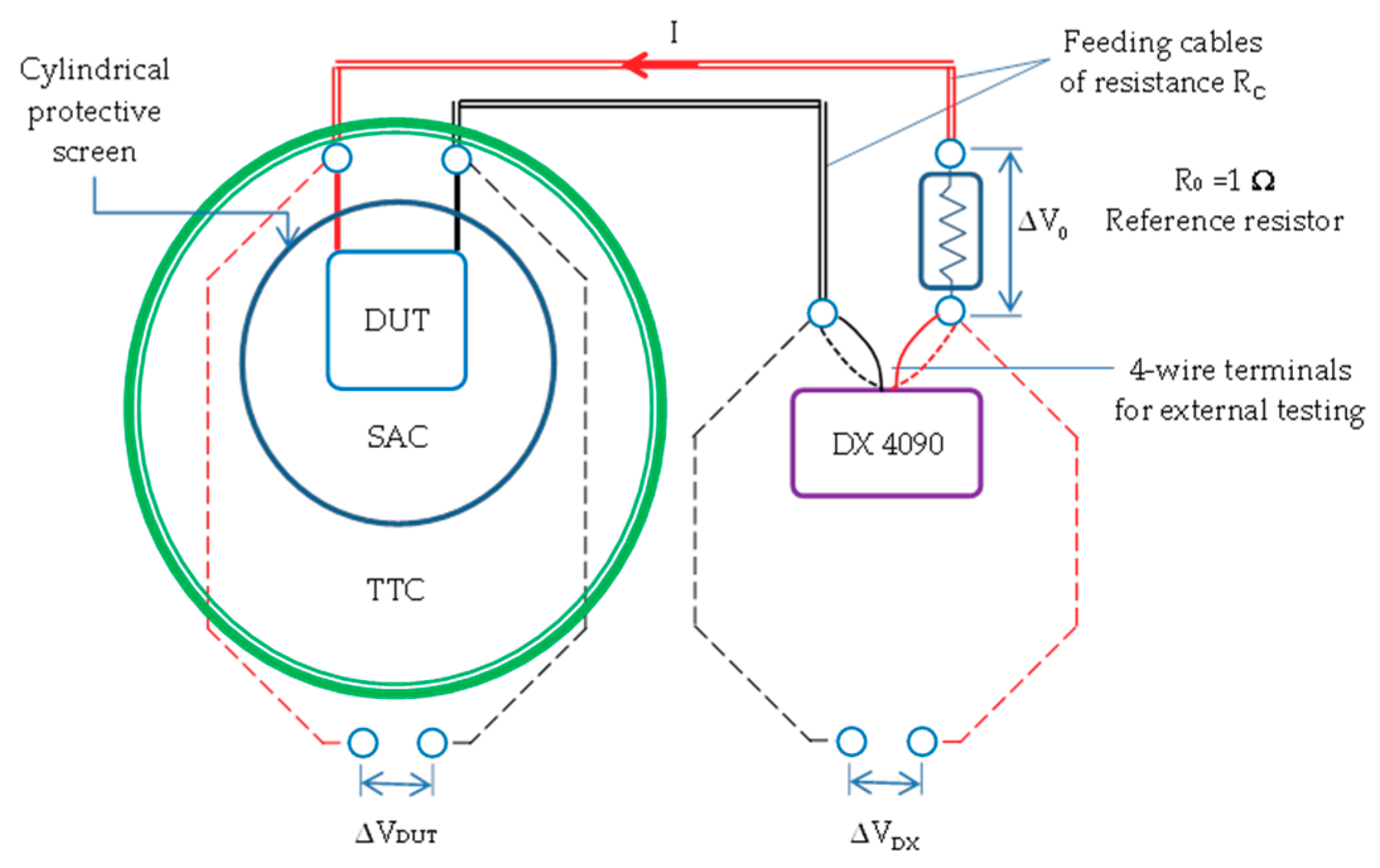
Figure 1 shows the scheme of the experimental arrangement, whose main parts are the Thermostatic Test Chamber (TTC), capable of operating from 203 K to 473 K with a stability of the set-point within ±0.1 K and the above-mentioned z-meter (DX 4090). Only the Peltier modules investigated were inserted in TTC while the other measurement tools such as the reference resistor (Fluke 742A-1, R0 = 1) shown in Figure 1, the voltmeters (Agilent 34420A 7½ Digit) and the thermocouples measurement bench (NI cDAQ-9178, TB-9212) not shown in the figure, were placed outside the TTC and kept in thermal equilibrium with the laboratory. For achieving a Still Air Chamber (SAC) inside TTC, a protective cylindrical screen has been arranged around the Device Under Test (DUT), avoiding on its exposed surfaces the air turbulences induced by the internal fan. At each established TTC set points chosen in the range 363 K, 213 K, the assigned test reference temperature was that picked on the inner surface of the cylindrical screen of SAC.
During the tests, the actual output current I set by the DX 4090 was checked to measure the voltage drop V0 at the potential leads of the reference resistor R0. This output current allows identifying the resistance RC of the feeding cables (double red and black lines in Figure 1) by measuring the voltage drop VDX and VDUT at the external connections of the DX 4090 and of the DUT, as shown in Figure 1. In this way, the resistance R’ measured by the DX 4090 is influenced by the resistances R0 and RC, and the figure of merit z’ obtained is altered as if the p-n series of the DUT was more resistive.
The corrected values for the resistance R of the p-n series (including, in this case, the resistance of connecting leads assembled at the factory) can be found subtracting R0 and RC, while the revised value z is obtained considering for this case the equality z R   = z R , so
R   = R ( R C + R 0 ) = R R 0 Δ V D X Δ V D U T Δ V 0 ,
z   = z R R = z Δ V D X Δ V D U T .
With the correct R value of the DUT, by subtracting the ohmic component Δ V Ω = I R from the measured voltage drop VDUT (or subtracting Δ V Ω = I R from VDX) it was possible to identify the total Seebeck voltage Δ V S produced at p-n junctions, associating to it the junction temperature difference Δ T S which produces this voltage, namely:
Δ V S   = Δ V D U T I R = Δ V D U T Δ V 0 (   R R 0 ) = Δ V D X Δ V 0 (   R R 0 ) = 2 N P ε Δ T S ,
where, N P is the number of thermoelectric pairs, and ε represents the equivalent Seebeck coefficient of the single junction of the assembled pillar series.
Since the direct measurement of the actual junction temperature of an assembled thermoelectric module is not an easy task, to obtain ε from the Seebeck voltage Δ V S expressed by Equation (3), the junction temperature difference Δ T S was estimated on the basis of the temperature difference Δ T P measured on the outside surfaces of the ceramic plates, introducing suitable corrections.
Different solutions were considered to identify the temperature of the outside surfaces of the ceramic plates. Around room temperature, with feeding currents less than 50 mA, a good temperature uniformity on these plates was verified using an infrared camera (FLIR 6753sc, cooled array 640 × 512 px, NETD < 18 mK). The operating range of the IR camera (253–623 K) has unfortunately inhibited its use in carrying out experiments down to 213 K. So, the surface temperatures were measured using type K thermocouples with exposed welded tip junctions (made using 0.076 mm diameter wires), placed in contact with the ceramic plate using a thin, highly reflective aluminum adhesive tape. The expected deviation between Δ T S and Δ T P ( Δ T S > Δ T P ) was estimated taking into account both the thermal resistance of the ceramic layers ( Al 2 O 3 ) and the pillars footprint area on the ceramic surface as spreading effect determined by the filling factors shown in Table 1.
Considering the actual ceramic thickness of the investigated Peltier modules, assuming feeding current in the range 25–40 mA, with some hypotheses on the maximum heat flux, exchanged at the junction (less than 0.1 W with I = 40 mA), a maximum deviation between Δ T P and Δ T S was estimated of the same order of accuracy expected in the temperature measurements. Despite this, in all experimental tests, a temperature correction Δ T ^ in the range 0.05–0.1 K was nevertheless applied on the measured Δ T P .

3. Experimental Results

All Peltier modules were tested in the range from 363 K to 213 K, covering the gap with temperature steps of about 30 K. Investigations were performed at a steady-state, checking the stability of the set-point imposed on the basis of the temperature measured inside the SAC. As mentioned in the previous section, the measured quantities were the voltage drops V0, VDX, and VDUT, as well as the resistance R of the module and the figure of merit z , the latter two measured using the DX 40490 (z-meter). The measurement protocol of the DX 4090 provides for polarity inversion; therefore, the voltage drops VDX and VDUT, obtained at each reference temperature Tref, were obtained by averaging the measured values with current I and −I, respectively. Following this approach for all modules, at each Tref, the measurement was repeated twice, waiting between the two measurements for the time necessary for the temperature to return to the set-point value.
The p-n series resistance R, the dimensionless figure of merit zT at Tref, and the Seebeck voltage Δ V S obtained by Equations (1)–(3) are summarized for the Peltier modules in Table 2, Table 3, Table 4, Table 5 and Table 6, specifying the test current I imposed by the DX 4090.
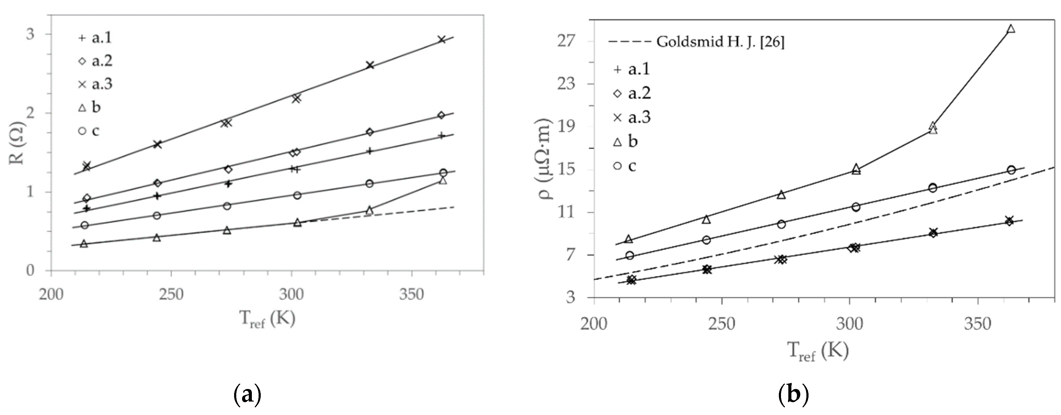
The obtained p-n series resistance R, in addition to the resistance of the semiconductor pillars, includes at each junction both the resistance of the soldering material and the connecting copper element. For all the modules tested, the trend of resistance R as a function of the reference temperature of the test is shown in Figure 2a. The trends are almost linear for all modules, with the exception of module b for which a deviation from the linear trend is observed for temperatures higher than the ambient one. Assuming that the assembled thermoelectric materials have common and comparable properties, Figure 2b shows their equivalent electrical resistivity obtained by means of the geometry of the pillars reported in Table 1. This resistivity is fairly similar for modules a.1, a.2, and a.3, while it assumes quite different values for modules b and c. In particular, the dependence of resistivity on temperature for module b deviates from linearity when the ambient temperature is exceeded. The dashed line shown in Figure 2b provides a comparison with the values found in the literature [14], which represent a possible trend of the average electrical resistivity for the p and n doped Bi 2 Te 3 bulk materials. The latter can be assumed in agreement with the measured trends for the grouped modules “a” and module c, while the same cannot be said for module b.
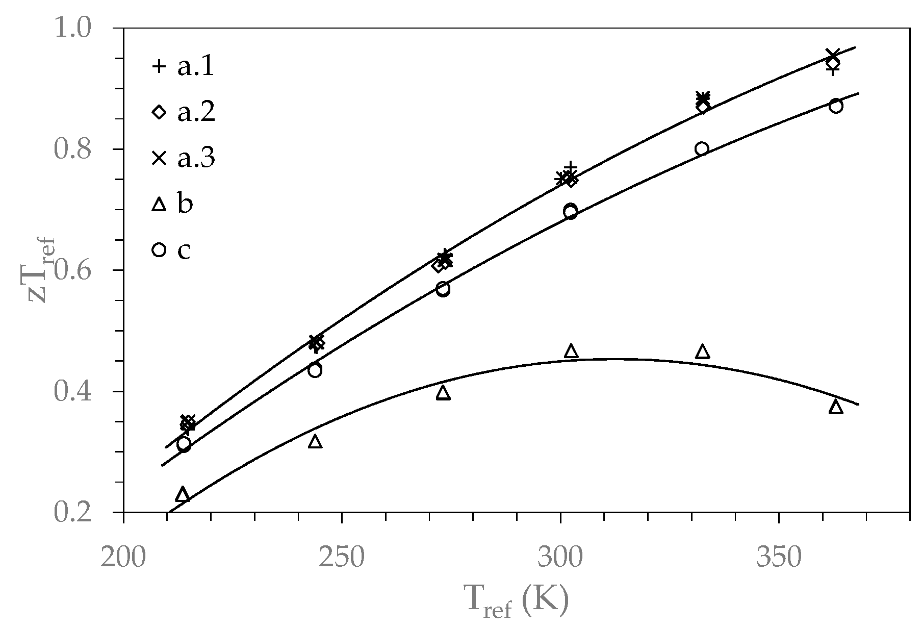
The similar behavior for the Peltier modules “a” is confirmed by the dimensionless figure of merit shown in Figure 3. For these modules, the measured trends zTref as the temperature changes are practically coincident and not so different from that obtained for module c. On the other hand, for module b the resulting figure of merit shows significantly different values and trends.
Since the values of zTref and found for the devices grouped as “a” are similar, it is possible to assume that their Seebeck coefficients are also similar. Therefore, in the following to estimate the Seebeck coefficient from the temperature difference Δ T P measured on the ceramic plates, only modules a.2, b, and c were considered.
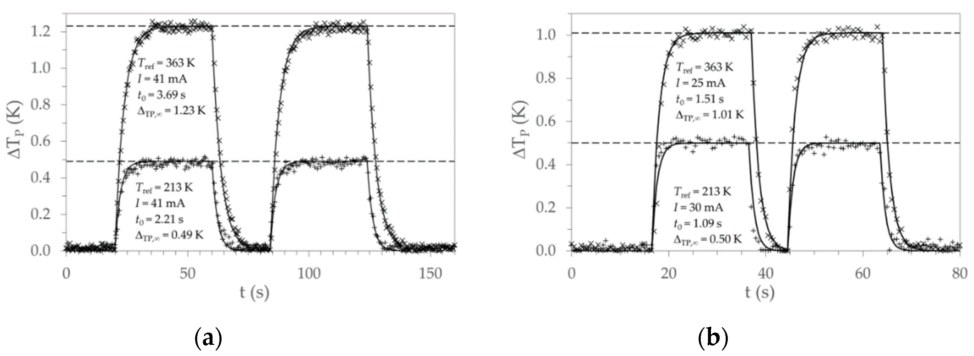
Figure 4 shows the trend over time of the temperature difference Δ T P for tests at maximum (363 K) and minimum temperature (213 K). Figure 4a,b refer to Peltier modules a.2 and c, respectively. Such a transient temperature difference is caused by the feeding current I, the characteristic time t 0 estimated using the DX 4090 is a useful parameter for the evaluation of the asymptotic value Δ T P , . In fact, assuming the time t 0 as the parameter that characterizes the response to a step input of a first-order linear system (RC lumped model), it was possible to obtain the best fit of the values Δ T P and evaluate the asymptotic temperature differences Δ T P , shown in Figure 4a,b with dashed lines. The agreement with the measured values is pointed out through the trends calculated with t 0 and Δ T P , , represented in the previous figures by the solid lines that reproduce the two sequential transients established by the measurement protocol of the DX 4090.
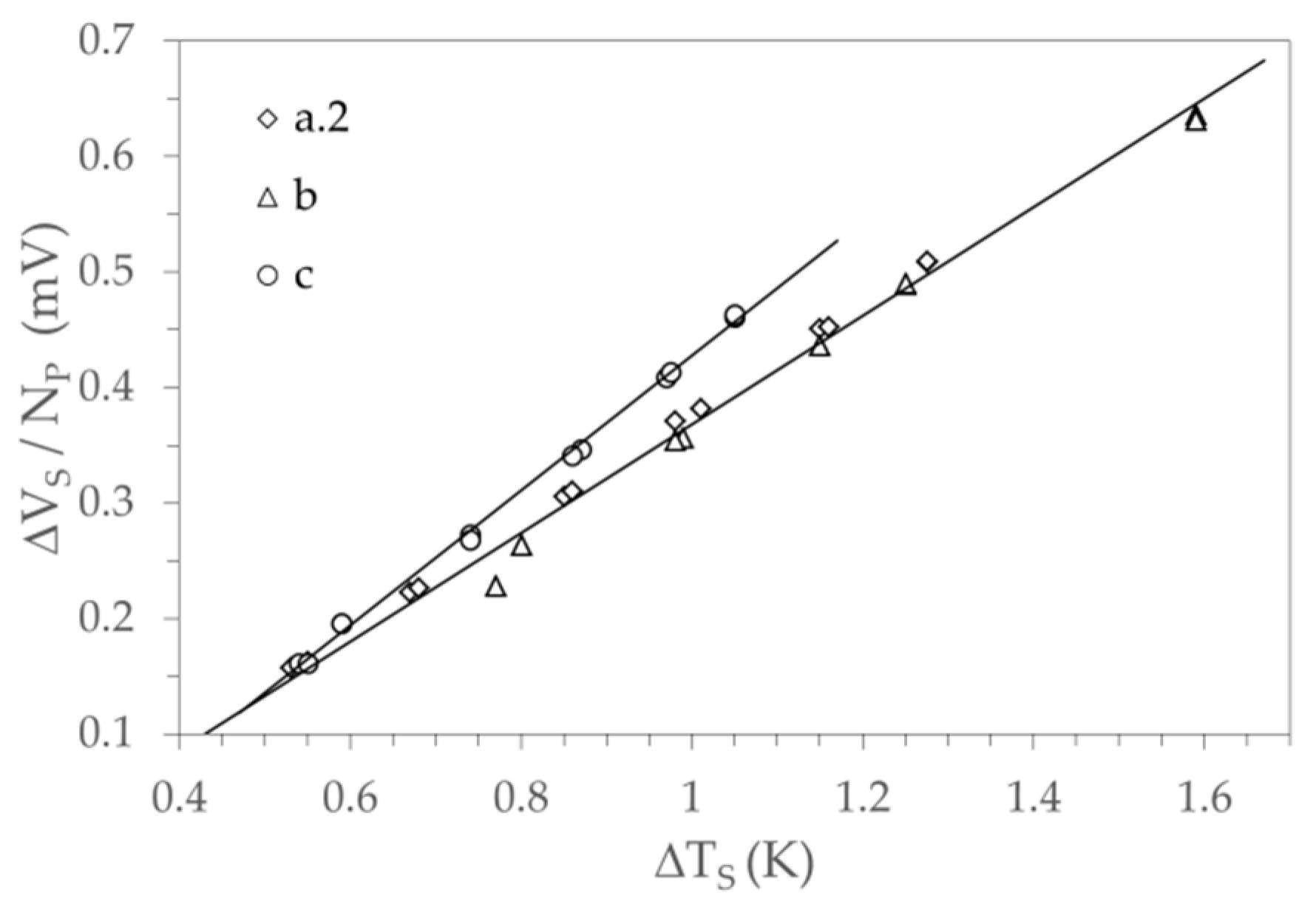
Since the estimated Δ T P , are systematically lower than the actual values of the temperature difference Δ T S of the junctions, as mentioned at the end of the previous section, a temperature correction Δ T ^ has been imposed, such that Δ T S = Δ T P , + Δ T ^ . In the performed tests, Δ T ^ = 0.05   K was assigned to modules a.2 and c, and Δ T ^ = 0.1   K to module b, due to the higher temperature noise noticed. Using the total Seebeck voltage measured at the leads of these modules, Figure 5 shows the Seebeck voltage of a single pair as a function of the estimated Seebeck temperature difference Δ T S for the junctions. In Figure 5, it is possible to observe the linear trend of the Seebeck voltage with a greater slope in the case of module c compared to modules a.2 and b. The same slope found for the latter two modules suggests similar Seebeck coefficients for both devices.
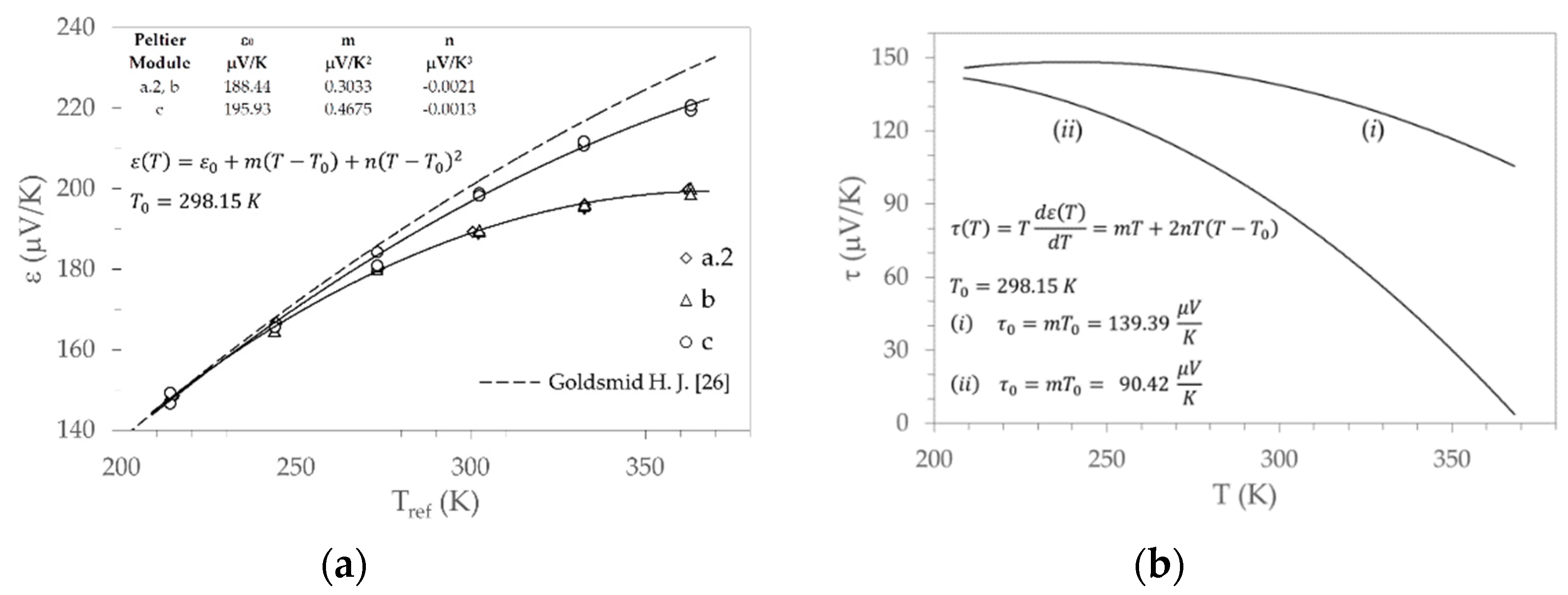
In fact, the equivalent Seebeck coefficients of the single junction resulting from Equation (3) and shown in Figure 6a as a function of the reference temperature of the test, highlight the same values for modules a.2 and b, and higher values with a different trend for module c. In this figure, the solid lines indicate the second-order polynomial fit, whose equation, coefficients, and reference temperature T 0 are shown inside the diagram box. The dashed line in the figure represents the theoretical trend proportional to T r e f 3 / 2 , as mentioned by Goldsmid [26] for the thermoelectric power of Bi 2 Te 3 .
From the equations for ε ( T ) , two temperature-dependent relationships were obtained for the Thomson coefficients τ ( T ) = T d ε ( T ) / d T for module c, and modules a.2 and b marked, hereafter as (i) and (ii) respectively. Figure 6b shows the trends for the Thomson coefficient with respect to temperature, and inside the diagram box the reported relationship refers to both cases (i) and (ii); parameters m and n are those shown in Figure 6a, while τ 0 = m T 0 is the Thomson coefficient at the reference temperature T 0 = 298.15   K .
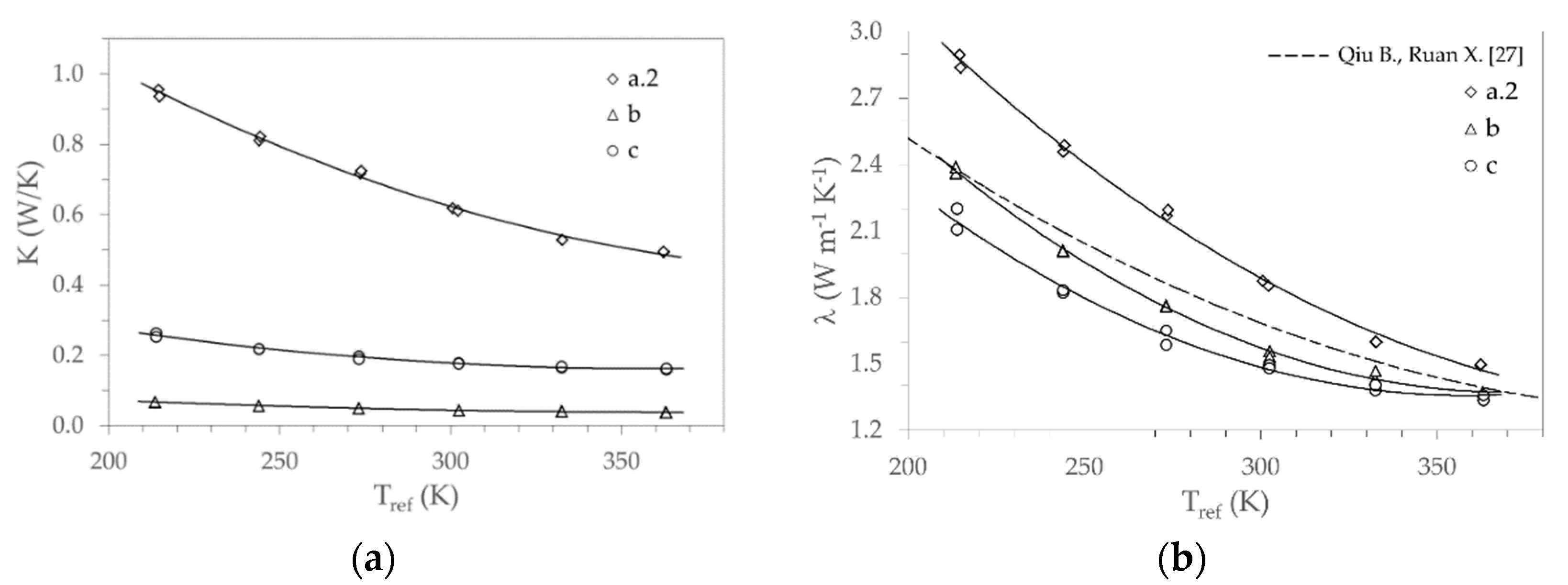
Finally, with the measured electric resistance R and the Seebeck coefficient estimated, from the well know relation that expresses the figure of merit z = ( 2 N P ε ) 2 / ( R   K ) , the thermal conductance K was obtained for modules a.2, b, and c, as shown in Figure 7a. Then, using the pillars geometry reported in Table 1, the equivalent thermal conductivity of the assembled thermoelectric materials was estimated. Figure 7b displays the values found against the reference temperature of the test, and the dashed line represents the trend of the average thermal conductivity with respect to the temperature for p and n doped Bi2Te3 bulk materials found in the literature [27].

4. Discussion

The results of the tests performed on various commercial Peltier modules, described in the previous section, make it possible to highlight the temperature dependence of their thermoelectric properties, in particular for the Seebeck coefficient ε , the electric resistivity ρ , and the thermal conductivity λ . These properties were mentioned as equivalent, because they were not obtained through investigations carried out directly on semiconductor materials, but indirectly through the same materials assembled in thermoelectric modules. Despite this, the values found and the comparison with the literature data gave them adequate reliability.
The temperature dependence of the thermoelectric properties makes it difficult to predict the actual performance of a device when used in the various temperature ranges. Furthermore, the impact of the Thomson effect on the performance of a device is not always so clear, especially when this effect overlaps the Joule effect caused by electrical resistivity if the latter also depends on the temperature.
The analysis was focused on the temperature dependence of the Seebeck coefficient ε that is responsible for the Thomson coefficients τ previously identified as (i) and (ii). The temperature dependence of the electrical resistivity ρ and of the thermal conductivity λ was also considered, adopting the values obtained for module c and a.2, in the cases (i) and (ii), respectively. Assuming in the temperature range investigated there is a linear and a quadratic trend for the resistivity and conductivity respectively, and taking into account what is specified for temperature dependence of the Seebeck coefficient (see Figure 6a), the general relationship of dependence on the temperature adopted for these properties ( y is the generic one) can be written as:
y ( T ) = y 0 + m ( T T 0 ) + n ( T T 0 ) 2 ,
where y 0 is the value ( ε 0 ,   ρ 0 ,   λ 0 ) of the considered property at the reference temperature T 0 . In Table 7, for a reference temperature T 0 = 298.15   K , the coefficients y 0 , m , and n are displayed for both cases (i) and (ii). For cases (i) and (ii), the geometry of the pillars and the number of pairs are those reported in Table 1 referring, respectively, to modules c and a.2. The effect produced by the temperature dependence of the thermoelectric properties was obtained by assuming the steady-state conditions and a one-dimensional thermal and electric field along pillars and solving the following governing equation:
λ d 2 T d x 2 ( T d ε d T ) j d T d x + ρ j 2 = 0 ,
where j is the current density, and the term in round brackets is the Thomson coefficient. The first term of Equation (5) represents the heat flux due to the Fourier conduction, while the second and the third terms characterize the heat generation due respectively to the Thomson and Joule effects. Dirichlet boundary conditions were imposed at the cold ( x = 0 ,   T = T C ) and hot ( x = L ,   T = T H ) side, thus the heat fluxes at these boundaries can be calculated as:
Q C = 2 N P I ( ε | x = 0 T C ) 2 N P A λ d T d x | x = 0 ,
Q H = 2 N P I   ( ε | x = L T H ) 2 N P A λ d T d x | x = L ,
where in both equations, the terms in round brackets are the Peltier coefficients on the cold and hot sides, A is the cross-section of the pillar ( A = W 2 ), while in both equations the first and second terms represent Peltier and Fourier heat fluxes on the cold and hot sides respectively. The coefficient of performance ( C O P ) of the device can be expressed by:
C O P = Q C / ( Q H Q C ) .
The solution for Equation (5) at any location x was obtained numerically by discretization of the computational domain ( 0 < x < L ). The domain was meshed with more than one hundred and one-dimensional elements; the set of equations was solved with a recursive finite differences algorithm (see, for example [28]), adopting a three-point approximation of the temperature gradient.
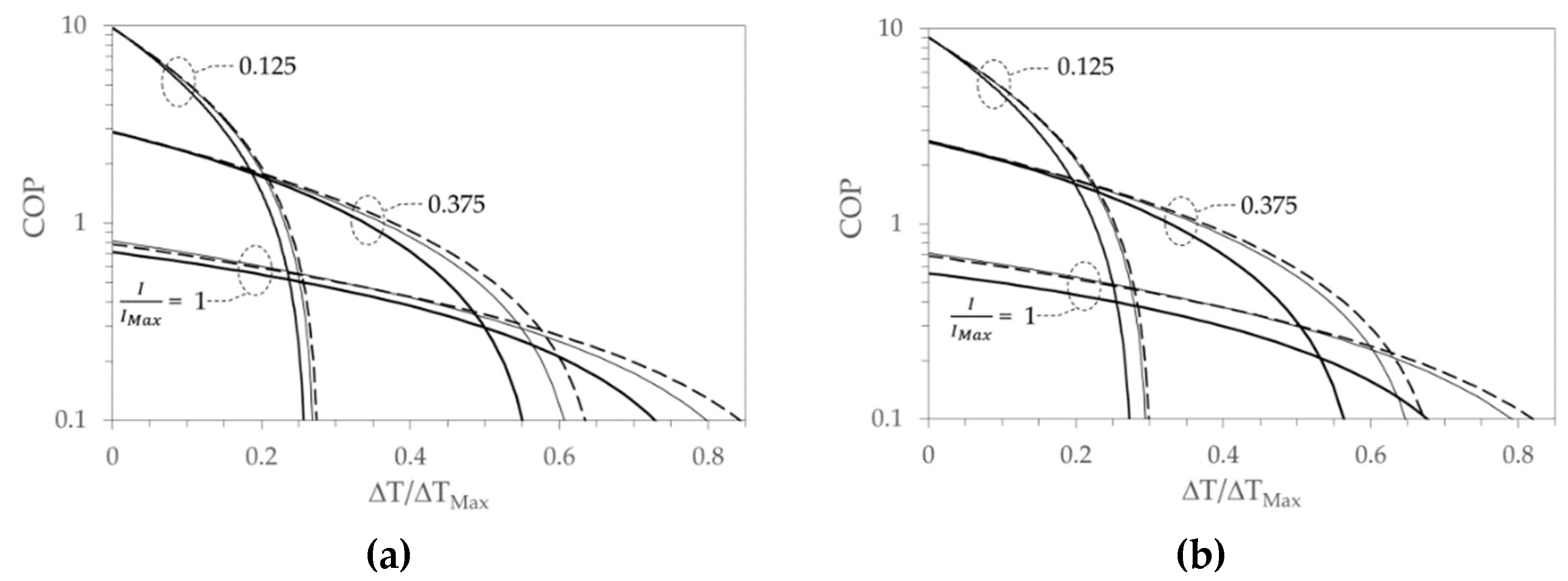
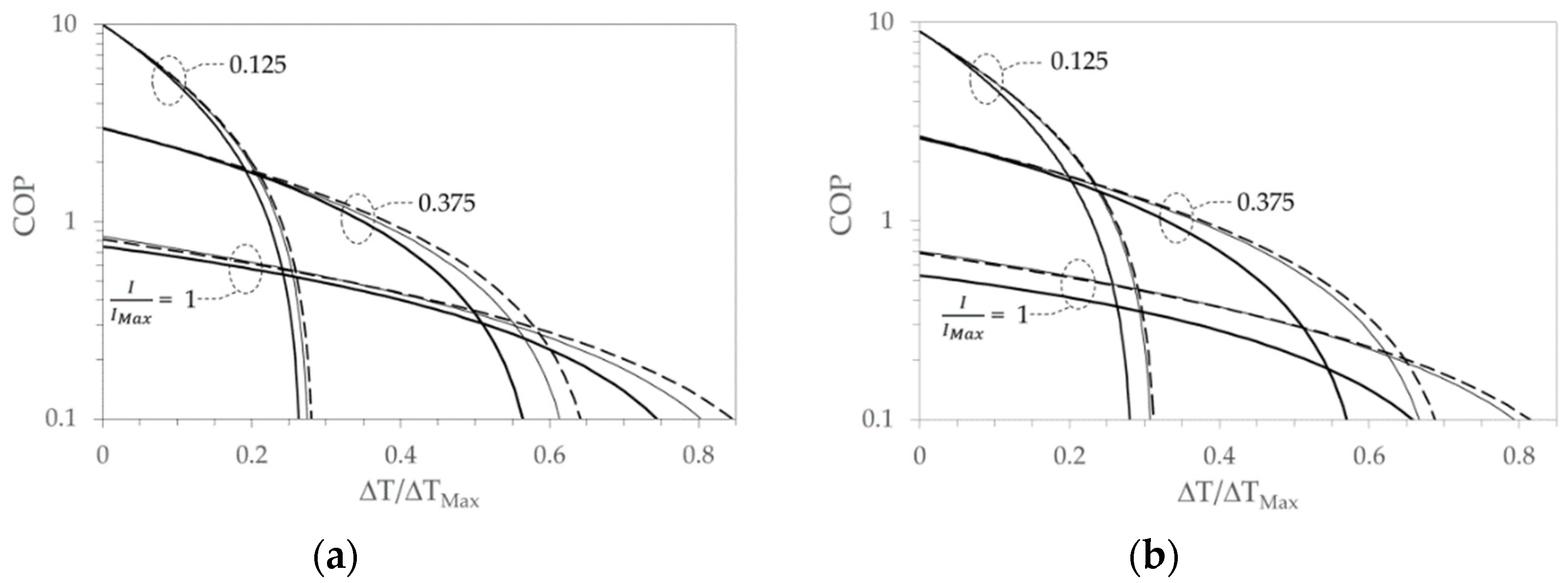
For both types of modules, (i) and (ii), using three different currents, I = I M A X , I = 0.375   I M A X , and I = 0.125   I M A X two cases were examined with constant hot side temperatures equal to T H = 298.15   K and T H = 323.15   K respectively. I M A X = ( A / L ) T H ε H / ρ H is current with which Q C , M A X is obtained when the cold side is kept at the temperature T H , and ε H , ρ H , are the Seebeck coefficient and the electrical resistivity at T H .
To explore these scenarios, the temperature T C of the cold side was varied in steps of 1 K from T H to T C , m i n assuming T C , m i n = ( 1 + 2 z H T H 1 ) / z H , with z H = ε H 2 / ( λ H ρ H ) , λ H the figure of merit and the thermal conductivity at T H , respectively. For each assigned T C , the temperature distribution along the pillars was calculated by solving Equation (5), and therefore determining the heat fluxes on the cold and hot sides with Equations (6) and (7), and the coefficient of performance with Equation (8).
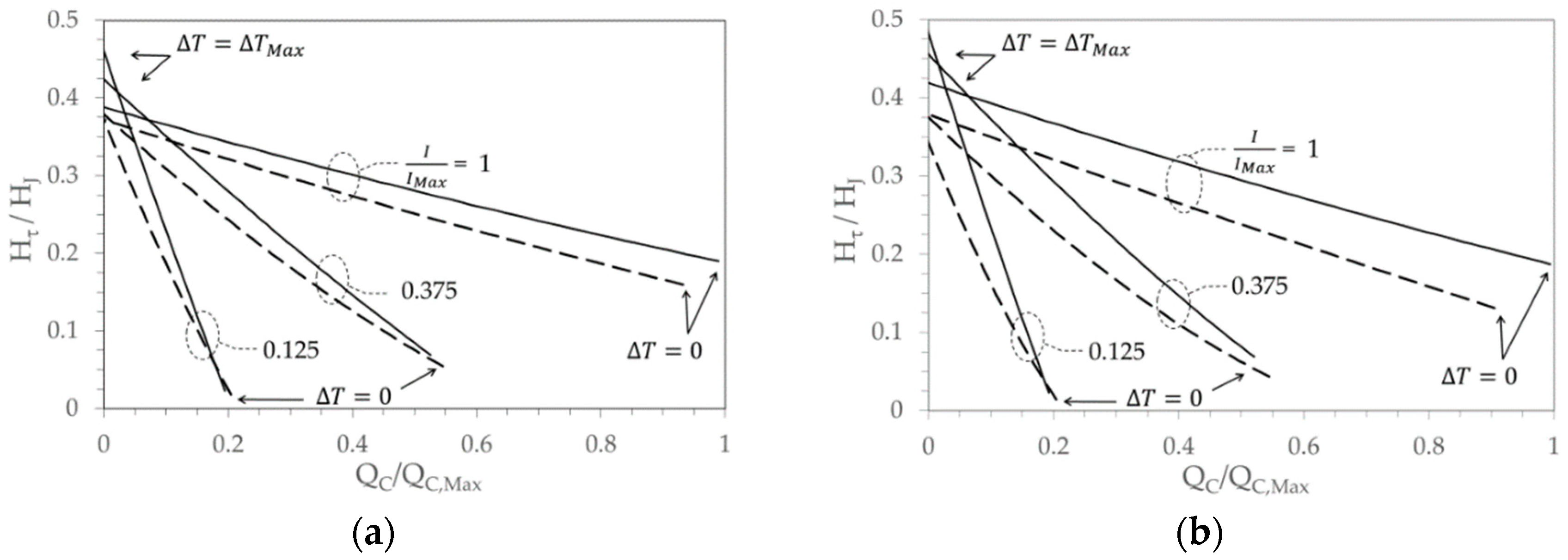
Positive Thomson heat (second term of Equation (5)) plays the role of reducing heat generation by Joule effect (third term of Equation (5)), and both cases (i) and (ii) show a positive Thomson heat at the cold side. Figure 8, for the cases at T H = 298.15   K and T H = 323.15   K , shows the ratio between Thomson heat and Joule effect calculated on the cold side as a function of the relative cooling capacity Q C / Q C , M a x for different values of the relative feeding current I / I M A X .
Since the Joule effect is always positive, the graphs in Figure 8 suggest an enhancement of the cooling capacity induced by the Thomson effect, in particular for high values of Δ T when the cooling capacity decreases. By increasing the cooling capacity, Δ T goes to zero, and the Thomson heat is minimum, but its value increases with the current. To clarify the real role assumed by the Thomson effect in improving the cooling capacity, it is more interesting to compare the experimental results obtained with an ideal circumstance. In this ideal case all the thermoelectric properties are assumed independent of the temperature (i.e., ε = ε H ,   ρ = ρ H ,   λ = λ H ), and, therefore, the Thomson effect is zero, and the heat generation by Joule effect along the pillars with a fixed current is constant.
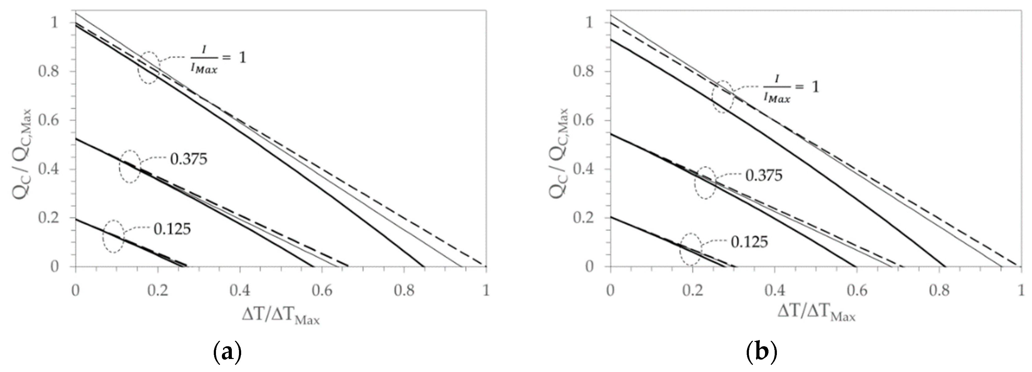
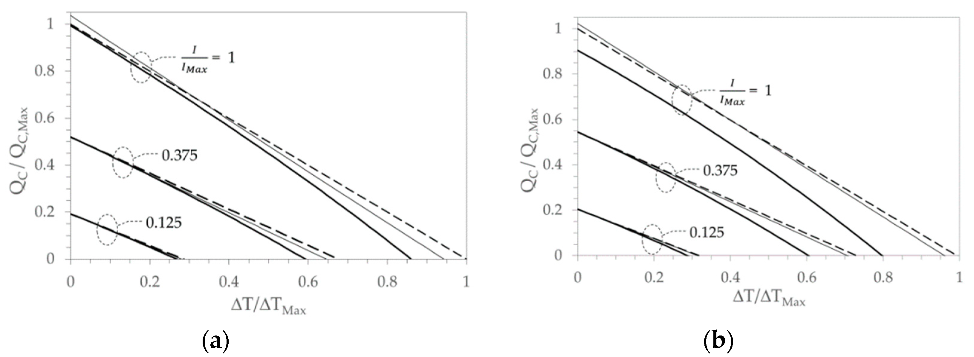
To underline the Thomson effect in relation to the temperature dependence of electrical resistivity and thermal conductivity, it can also be useful to make a comparison with another hypothetical scenario. In this scenario, the Seebeck coefficient is temperature dependent, as established in the cases (i) and (ii), while the electrical resistivity and the thermal conductivity are both independent of temperature (i.e., ρ = ρ H ,   λ = λ H ). Thes scenarios, for both cases (i) and (ii), is shown in Figure 9, with T H = 298.15   K , and in Figure 10, with T H = 323.15   K . In the two figures, the trends of the relative cooling capacity Q C / Q M a x as a function of the relative temperature difference Δ T / Δ T M a x , compared for different values of the relative feeding current I / I M A X , are quite similar. With the adoption of the previous defined T C , m i n , the maximum temperature difference depends on the temperature of the hot side chosen, named Δ T M a x =   T H   T C , m i n .
In the previous diagrams, it can be seen that the results obtained with the temperature-independent properties, represented by the dashed lines, show a linear trend with respect to the relative temperature difference Δ T / Δ T M a x . The slope depends on the feeding current, i.e., 2 N P [ ε H I ( A / L ) λ H ] / Q C , M a x , and reproduces the typical trend proposed in datasheets of commercial devices. On the contrary, the experimental results obtained, represented by the thick solid lines, show the influence of the temperature-dependent thermoelectric properties with an overall reduced cooling capacity, in particular for both high feeding currents, and temperature differences. With a low feeding current there are no significant differences regardless of the assumptions about the thermoelectric properties, while at high currents, a reduced cooling capacity is observed for all the temperature differences between the junctions. When Δ T approaches zero, the reduced cooling capacity is caused by the different temperature gradients resulting on the cold side. The temperature gradient is influenced by the temperature profile along the pillars, which depends on the electrical resistivity and thermal conductivity. Furthermore, the thermal gradient on the cold side in the case of temperature-dependent properties is higher than that found in the ideal case of temperature-independent properties. In this way, with the same Peltier heat flux for Δ T = 0 , the Fourier heat conduction increases. Therefore, with regard to case (ii), Figure 9b and Figure 10b show at the higher current a greater deviation from ideal conditions due to the higher thermal conductivity value (see Table 7), compared with Figure 9a and Figure 10a, which refer to case (i). At the lower currents investigated, this fact was negligible.
The assumption that only the Seebeck coefficient depends on the temperature allows us to better highlight the contribution of the Thomson effect. On the cold side, as shown in Figure 8a,b, the magnitude of the Thomson heat compared with the heat generation by Joule effect is greater at higher Δ T and with lower cooling capacities. In addition, the Thomson heat, although reduced, does not vanish at smaller Δ T and with greater cooling capacity, and when the temperature difference approaches zero, it clearly increases with the feeding current. The thin solid lines in Figure 9a,b shows these evidence. At the lowest current set, the effect induced by Thomson heat is practically undetectable and its influence is observable due to the increase in the feeding current. At higher temperature differences, the trend of the cooling capacity shifts toward the ideal condition (temperature-independent properties), but remains even lower. Otherwise, with higher feeding current and at the lower temperature difference, the cooling capacity exceeds that obtained in the ideal condition because on the cold side, the heat generated by Joule effect is reduced due to the heat absorbed by the Thomson effect, and consequently the local thermal gradient and the Fourier heat contribution are reduced. A further confirmation of this is given by the coefficients of performance reported in Figure 11 and Figure 12, for which it is difficult to highlight an improvement in the performance of the device compared with the event that only the Seebeck coefficient is temperature-dependent (solid thin lines). Under these conditions, for the thermoelectric modules investigated, only with the maximum current, a small improvement in the performance was observed.
5. Conclusions

Based on what emerged from the experimental investigations and analyses, it is possible to affirm that the intrinsic Thomson effect appears clearly when all the properties are temperature dependent. Furthermore, it seems inappropriate to separate the temperature-dependence of the Seebeck coefficient from the temperature dependence of the other thermoelectric properties as sometimes found in the literature. About the investigated commercial Peltier modules and their measured thermoelectric properties, some final remarks can be summarized as follows.
(1) No benefits on the estimated performances in the whole operating range can be ascribed to the Thomson effect. In fact, the cooling capacity of the considered devices is always reduced compared to the ideal condition of temperature-independent properties. This behavior is because the Joule heat dominates the thermal events inside the device.
(2) In datasheets commonly available, the Thomson effect is almost certainly not considered. In fact, at a giving feeding current, the typical linear trend between cooling capacity and temperature difference among junctions identifies this eventuality (see Figure 9 and Figure 10).
(3) In current bulk materials such as Bi 2 Te 3 , it seems difficult to improve the performances by enhancing the Thomson effect while simultaneously reducing the Joule contribution. For this purpose, the new class of thermoelectric materials mentioned in the literature [18,19,20,21,22] could introduce stimulating chances.

Author Contributions

Conceptualization, investigation, writing—original draft preparation, V.G.; investigation, writing—review and editing, E.C. All authors have read and agreed to the published version of the manuscript.

Funding

This research received no external funding.

Acknowledgments

We would like to thank M. Bressan for his support in the realization of the experimental arrangement.

Conflicts of Interest

The authors declare no conflict of interest.

References

  1. Xu, Q.; Riffat, S.; Zhang, S. Review of Heat Recovery Technologies for Building Applications. Energies 2019, 12, 1285–1306. [Google Scholar] [CrossRef] [Green Version]
  2. Yang, J.; Stabler, F.R. Automotive applications of thermoelectric materials. J. Electron. Mater. 2009, 38, 1245–1251. [Google Scholar] [CrossRef]
  3. Ahn, D.; Choi, K. Performance Evaluation of Thermoelectric Energy Harvesting System on Operating Rolling Stock. Micromachines 2018, 9, 359–370. [Google Scholar] [CrossRef] [PubMed] [Green Version]
  4. Mahajan, R.; Chiu, C.-P.; Chrysler, G. Cooling a microprocessor chip. Proc. IEEE 2006, 94, 1476–1486. [Google Scholar] [CrossRef]
  5. Li, J.; Ma, B.; Wang, R.; Han, L. Study on a cooling system based on thermoelectric cooler for thermal management of high-power LEDs. Microelectron. Reliab. 2011, 51, 2210–2215. [Google Scholar] [CrossRef]
  6. Russel, M.K.; Ewing, D.; Ching, C.Y. Characterization of a thermoelectric cooler based thermal management system under different operating conditions. Appl. Therm. Eng. 2003, 50, 652–659. [Google Scholar] [CrossRef]
  7. Giaretto, V.; Ballatore, A.; Passerone, C.; Desalvo, P.; Matta, M.; Saglietto, A.; De Salve, M.; Gaita, F.; Panella, B.; Anselmino, M. Thermodynamic properties of atrial fibrillation cryoablation: A model-based approach to improve knowledge on energy delivery. J. R. Soc. Interface 2019, 16, 20190318. [Google Scholar] [CrossRef]
  8. Giaretto, V.; Passerone, C. Mirror image technique for the thermal analysis in cryoablation: Experimental setup and validation. Cryobiology 2017, 79, 56–64. [Google Scholar] [CrossRef]
  9. Teffah, K.; Zhang, Y.; Mou, X. Modeling and Experimentation of New Thermoelectric Cooler-Thermoelectric Generator Module. Energies 2018, 11, 576–586. [Google Scholar] [CrossRef] [Green Version]
  10. Attivissimo, F.; Carducci, C.G.C.; Lanzolla, A.M.L.; Spadavecchia, M. An Extensive Unified Thermo-Electric Module Characterization Method. Sensors 2016, 16, 2114–2133. [Google Scholar] [CrossRef]
  11. Chen, J.; Yan, Z.; Wu, L. The influence of Thomson effect on the maximum power output and maximum efficiency of a thermoelectric generator. J. Appl. Phys. 1996, 79, 8823–8828. [Google Scholar] [CrossRef]
  12. Huang, M.J.; Yen, R.H.; Wang, A.B. The influence of the Thomson effect on the performance of a thermoelectric cooler. Int. J. Heat Mass Transf. 2005, 48, 413–418. [Google Scholar] [CrossRef]
  13. Du, C.Y.; Wen, C.D. Experimental investigation and numerical analysis for one-stage thermoelectric cooler considering Thomson effect. Int. J. Heat Mass Transf. 2011, 54, 4875–4884. [Google Scholar] [CrossRef]
  14. Lee, H. The Thomson effect and the ideal equation on thermoelectric coolers. Energy 2013, 56, 61–69. [Google Scholar] [CrossRef]
  15. Feng, Y.; Chen, L.; Meng, F.; Sun, F. Influences of the Thomson Effect on the Performance of a Thermoelectric Generator-Driven Thermoelectric Heat Pump Combined Device. Entropy 2018, 20, 29. [Google Scholar] [CrossRef] [Green Version]
  16. Lam, T.T.; Yuan, S.W.K.; Fong, E.; Fischer, W.D. Analytical study of transient performance of thermoelectric coolers considering the Thomson effect. Int. J. Therm. Sci. 2018, 435–448. [Google Scholar] [CrossRef]
  17. Yamashita, O. Resultant Seebeck coefficient formulated by combining the Thomson effect with the intrinsic Seebeck coefficient of a thermoelectric element. Energy Convers. Manag. 2009, 50, 2394–2399. [Google Scholar] [CrossRef]
  18. Snyder, G.J.; Khanna, R.; Toberer, E.S.; Heinz, N.A.; Seifert, W. Improved Thermoelectric Cooling Based on the Thomson Effect. Proc. SPIE Baltim. 2016, 9821, 98210J. [Google Scholar] [CrossRef] [Green Version]
  19. Sadia, Y.; Aminov, Z.; Mogilyansky, D.; Gelbstein, Y. Texture anisotropy of higher manganese silicide following arc-melting and hot-pressing. Intermetallics 2016, 68, 71–77. [Google Scholar] [CrossRef]
  20. Cohen, I.; Kaller, M.; Komisarchik, G.; Fuks, D.; Gelbstein, Y. Enhancement of the thermoelectric properties of n-type PbTe by Na and Cl co-doping. J. Mater. Chem. C 2015, 37, 9559–9564. [Google Scholar] [CrossRef]
  21. Xing, Y.; Liu, R.; Liao, J.; Zhang, Q.; Xia, X.; Wang, C.; Huang, H.; Chu, J.; Gu, M.; Zhu, T.; et al. High-efficiency half-Heusler thermoelectric modules enabled by self-propagating synthesis and topologic structure optimization. Energy Environ. Sci. 2019, 12, 3390–3399. [Google Scholar] [CrossRef]
  22. Rull-Bravo, M.; Moure, A.; Fernàndez, J.F.; Martin-Gonzàlez, M. Skutterudites as thermoelectric materials: Revisited. RSC Adv. 2015, 5, 41653–41667. [Google Scholar] [CrossRef]
  23. Harman, T.C. Special Techniques for Measurement of Thermoelectric Properties. J. Appl. Phys. 1958, 29, 1373–1374. [Google Scholar] [CrossRef]
  24. De Marchi, A.; Giaretto, V. An accurate new method to measure the dimensionless figure of merit of thermoelectric devices based on the complex impedance porcupine diagram. Rev. Sci. Instrum. 2011, 82, 104904. [Google Scholar] [CrossRef] [Green Version]
  25. Gromov, G.; Kondratiev, D.; Rogov, A.; Yershova, L. Z-meter: Easy-to-use Application and Theory. In Proceedings of the 6th European Workshop on Thermoelectricity of the European Thermoelectric Society, Freiburg im Breisgau, Germany, 20–21 September 2001; pp. 1–8. [Google Scholar]
  26. Goldsmid, H.J. The Electrical Conductivity and Thermoelectric Power of Bismuth Telluride. Proc. Phys. Soc. 1958, 71, 633–646. [Google Scholar] [CrossRef]
  27. Qiu, B.; Ruan, X. Molecular Dynamics Simulations of the Thermal Conductivity of Bismuth Telluride Using Two-Body Interatomic Potentials. In Proceedings of the ASME Heat Transfer Summer Conference, San Francisco, CA, USA, 19–23 July 2009. HT2009-88157. [Google Scholar]
  28. Ozisik, M.N. Finite Difference Methods in Heat Transfer; CRC Press: Boca Raton, FL, USA, 1994. [Google Scholar]
Figure 1. Scheme of the experimental arrangement. DX 4090 is the z-meter, TTC is the Thermostatic Test Chamber, SAC is the Still Air Chamber, and DUT is the Device Under Test. Solid and double red and black lines are the feeding cables, while the dashed ones represent the signal wires.
Metals 10 00291 g001
Figure 2. (a) Assembled p-n series resistance R given by Equation (1) versus the test reference temperature for each Peltier module; (b) Equivalent electrical resistivity of the assembled thermoelectric materials versus test reference temperature for each Peltier module. The dashed line represents a possible trend in temperature of the average electrical resistivity for the p and n doped Bi2Te3 bulk materials, as found in the literature [26].
Metals 10 00291 g002
Figure 3. Measured dimensionless figure of merit for the investigated Peltier modules versus the test reference temperature.
Metals 10 00291 g003
Figure 4. Examples of the transient temperature difference measured on the external surface of the ceramic plates versus time for the two cases with maximum and minimum reference temperature. Solid lines represent the trend calculated with a lumped model that uses the characteristic time t 0 provided by the DX 4090; dashed lines represent the asymptotic values Δ T P , . (a) module a.2; (b) module c.
Metals 10 00291 g004
Figure 5. Seebeck voltage of a single pair (total Seebeck voltage divided by the number of pairs NP) versus the estimated temperature difference Δ T S of the Seebeck junction.
Metals 10 00291 g005
Figure 6. (a) Equivalent single junction Seebeck coefficients versus test reference temperature for modules a.2, b and c. The fitting equation and regression coefficients are shown in the diagram box. The solid lines represent the fit trends, and the dashed line is the theoretical trend mentioned by Goldsmid [26]; (b) Thomson coefficient trends for module c (i) and modules a.2 and b (ii). Parameters m and n are those shown in (a), and τ 0 values are the Thomson coefficients at T 0 .
Metals 10 00291 g006
Figure 7. (a) Thermal conductance versus the reference temperature of the test for modules a.2, b, and c.; (b) Equivalent thermal conductivity of the assembled thermoelectric materials versus the reference temperature of the test for modules a.2, b, and c. The dashed line represents a possible trend in temperature of the average thermal conductivity for p and n doped Bi2Te3 bulk materials, as found in the literature [27].
Metals 10 00291 g007
Figure 8. Cold side: ratio between Thomson heat and Joule effect versus the relative cooling capacity, solid line case (i), dashed line case (ii). (a) T H = 298.15   K ; (b) T H = 323.15   K .
Metals 10 00291 g008
Figure 9. T H = 298.15   K . Relative cooling capacity Q C / Q M a x against the relative temperature difference Δ T / Δ T M a x for different relative feeding currents I / I M A X . The thick solid lines represent the performed experiment; the dashed lines refer to thermoelectric properties independent of temperature, the thin solid lines indicate the scenario in which the Seebeck coefficient depends on the temperature, while both the electrical resistivity and the thermal conductivity are temperature independent: (a) case (i); (b) case (ii).
Metals 10 00291 g009
Figure 10. T H = 323.15   K . Relative cooling capacity Q C / Q M a x against the relative temperature difference Δ T / Δ T M a x for different relative feeding currents I / I M A X . The thick solid lines represent the performed experiment, the dashed lines refer to thermoelectric properties independent of temperature, the thin solid lines indicate the scenario in which the Seebeck coefficient depends on the temperature, while both the electrical resistivity and the thermal conductivity are temperature independent: (a) case (i); (b) case (ii).
Metals 10 00291 g010
Figure 11. T H = 298.15   K . Coefficient of performance against the relative temperature difference Δ T / Δ T M a x at different relative feeding current I / I M A X , thick solid lines represent the performed experiment, dashed lines refer to temperature-independent thermoelectric properties, thin solid lines denote the scenario in which the Seebeck coefficient is temperature-dependent and both electrical resistivity and thermal conductivity are temperature independent: (a) case (i); (b) case (ii).
Metals 10 00291 g011
Figure 12. T H = 323.15   K . Coefficient of performance against the relative temperature difference Δ T / Δ T M a x at different relative feeding current I / I M A X , thick solid lines represent the performed experiment, dashed lines refer to temperature-independent thermoelectric properties, thin solid lines denote the scenario in which the Seebeck coefficient is temperature-dependent and both electrical resistivity and thermal conductivity are temperature independent: (a) case (i); (b) case (ii).
Metals 10 00291 g012
Table 1. Number of pairs and some geometric features of the investigated Peltier modules.
Peltier
Module
Number
of Pairs
NP
Module Thickness (mm)Pillar SizeCopper Thickness
(mm)
Ceramic Thickness
(mm)
Filling
Factor
(%)
Height L
(mm)
Side W
(mm)
a.11273.41.51.50.350.6036
a.21273.31.31.30.350.6527
a.31273.91.91.30.350.6527
b175.42.71.50.351.0014
c *501.30.30.60.050.4556
* The external surface of the ceramic plates is metalized.
Table 2. Peltier module a.1: p-n series resistance, the figure of merit, and Seebeck voltage (I = 41 mA).
Tref (K) R   ( Ω ) zTref Δ Vs (mV)Tref (K) R   ( Ω ) zTref Δ Vs (mV)
362.351.720.9354.72273.551.100.6334.18
362.351.720.9354.70273.851.110.6233.94
332.551.520.8850.42243.850.950.4723.98
332.651.520.8850.42244.250.940.4724.58
300.151.290.7541.53214.550.790.3416.83
302.351.290.7743.35214.850.800.3416.56
Table 3. Peltier module a.2: p-n series resistance, the figure of merit, and Seebeck voltage (I = 41 mA).
Tref (K) R   ( Ω ) zTref Δ Vs (mV)Tref (K) R   ( Ω ) zTref Δ Vs (mV)
362.251.980.9564.64273.451.290.6238.86
362.351.980.9664.73273.751.290.6239.42
332.551.770.8857.28244.051.120.4828.32
332.651.760.8857.51244.351.110.4828.80
300.551.490.7547.13214.550.910.3520.69
302.151.510.7548.48214.850.930.3520.00
Table 4. Peltier module a.3: p-n series resistance, the figure of merit, and Seebeck voltage (I = 41 mA).
Tref (K) R   ( Ω ) zTref Δ Vs (mV)Tref (K) R   ( Ω ) zTref Δ Vs (mV)
362.352.940.9493.93272.051.870.6156.00
362.352.940.9493.79273.651.880.6157.08
332.752.610.8783.16244.051.610.4841.47
332.552.610.8783.22244.451.600.4842.00
302.452.200.7571.05214.551.320.3429.87
301.752.180.7569.37214.851.350.3528.64
Table 5. Peltier module b: p-n series resistance, the figure of merit, and Seebeck voltage (I = 25 mA).
Tref (K) R   ( Ω ) zTref Δ Vs (mV)Tref (K) R   ( Ω ) zTref Δ Vs (mV)
362.951.150.3810.82273.150.520.406.06
363.051.150.3710.74273.150.520.406.02
332.450.780.478.32243.850.420.324.48
332.550.760.478.34243.850.420.324.48
302.450.610.477.41213.550.350.233.87 *
302.450.620.477.42213.550.350.233.87 *
* Measurement performed with feeding current I = 30 mA.
Table 6. Peltier module c: p-n series resistance, the figure of merit, and Seebeck voltage (I = 25 mA).
Tref (K) R   ( Ω ) zTref Δ Vs (mV)Tref (K) R   ( Ω ) zTref Δ Vs (mV)
363.051.250.8723.05273.150.830.5713.64
363.051.250.8723.18273.150.820.5713.40
332.351.110.8020.45243.850.700.449.78
332.351.100.8020.66243.850.700.439.78
302.350.950.7017.31213.850.580.318.07 *
302.350.960.7017.06213.850.580.318.07 *
* Measurement performed with feeding current I = 30 mA.
Table 7. Coefficients for the temperature dependence relationship of ε ,   ρ ,   λ . ( T 0 = 298.15   K ).
CaseProperty y 0 mn
(i) ε ( T ) , V/K195.930.4675−0.0013
ρ ( T ) , m11.3900.0541-
λ ( T ) , W/(m K)1.4921−0.00453.78⋅10−5
(ii) ε ( T ) , V/K188.440.3033−0.0021
ρ ( T ) , m7.68130.0370-
λ ( T ) , W/(m K)1.9033−0.00883.34⋅10−5