Article

The Effect of Electroslag Remelting on the Microstructure and Mechanical Properties of CrNiMoWMnV Ultrahigh-Strength Steels

1
Materials and Mechanical Engineering, Centre for Advanced Steels Research, University of Oulu, P.O. Box 4200, 90014 Oulu, Finland
2
Steel Technology Department, Central Metallurgical Research and Development Institute (CMRDI), Helwan, Cairo 11421, Egypt
*
Author to whom correspondence should be addressed.
Metals 2020, 10(2), 262; https://doi.org/10.3390/met10020262
Submission received: 27 January 2020 / Revised: 13 February 2020 / Accepted: 14 February 2020 / Published: 17 February 2020

Abstract

:
The effect of electroslag remelting (ESR) with CaF2-based synthetic slag on the microstructure and mechanical properties of three as-quenched martensitic/martensitic-bainitic ultrahigh-strength steels with tensile strengths in the range of 1250–2000 MPa was investigated. Ingots were produced both without ESR, using induction furnace melting and casting, and with subsequent ESR. The cast ingots were forged at temperatures between 1100 and 950 °C and air cooled. Final microstructures were investigated using laser scanning confocal microscopy, field emission scanning electron microscopy, electron backscatter diffraction, electron probe microanalysis, X-ray diffraction, color etching, and micro-hardness measurements. Mechanical properties were investigated through measurement of hardness, tensile properties and Charpy-V impact toughness. The microstructures of the investigated steels were mainly auto-tempered martensite in addition to small fractions of retained austenite and bainite. Due to the consequences of subtle modifications in chemical composition, ESR had a considerable impact on the final microstructural features: Prior austenite grain, effective martensite grain, and lath sizes were refined by up to 52%, 38%, and 28%, respectively. Moreover, the 95th percentiles in the cumulative size distribution of the precipitates decreased by up to 18%. However, ESR had little, if any, the effect on microsegregation. The variable effects of ESR on mechanical properties and how they depend on the initial steel composition are discussed.

1. Introduction

In steels, ultrahigh strength can be achieved through a combination of several mechanisms like grain refinement, precipitation strengthening, solid solution strengthening, dislocation strengthening, and texture strengthening. Many of these mechanisms are enhanced through the use of thermomechanical treatments [1,2,3,4]. Bainitic and lath martensitic microstructures are commonly used to achieve good combinations of ultrahigh strength, high ductility, and high impact toughness. High-carbon nanoscale carbide-free bainite and with retained austenite (RA) gives high ductility through transformation-induced plasticity (TRIP) [5,6,7], but at the expense of the weldability that is desired for structural steels.
The microstructure of martensitic or bainitic steels is subdivided into the following units: Prior austenite grains, packets, blocks, sub-blocks, and laths, with unit size decreasing from left to right. The prior austenite grains are divided into packets, which consist of blocks of laths with the same habit plane. These blocks contain sub-blocks in which the laths have similar crystal orientations. The boundaries between packets and blocks have high-angle misorientations while the boundaries between sub-blocks and laths have low-angle misorientations [8,9,10].
Strength and toughness properties can be improved simultaneously by grain refining, which can be achieved, for example, by the pinning of the austenite grain boundaries by fine precipitates, which are stable at high temperatures [11]. A high number density of fine precipitates leads to enhanced pinning of the grain boundaries, which subsequently leads to a reduction of the final prior austenite grain, packet, and block sizes and a significant effect on the mechanical properties of the steel. It was observed by Wang et al. [12] that the yield strength of 17CrNiMo6 martensitic steel is increased by 235 MPa by reducing the prior austenite grain size (PAGS) by 33% and the Charpy U-notch impact energy at 77 K was enhanced more than eight-fold.
In addition to the above strengthening factors, additional strengthening can be achieved through precipitation. In the case of dislocation bowing between precipitates, the Orowan relationship [13] shows that the yield strength increment from precipitation increases with increasing volume fraction and decreasing size of the precipitates. In the case of tempered martensite, the optimum combination of volume fraction and size depends on the tempering temperature and time [14].
The low-cost ESR process can be used to achieve high-quality steel and obtain a homogenous microstructure with a low degree of segregation and porosity because of nearly directional solidification from a tiny refined-molten pool. The significant effect of ESR on the non-metallic inclusion (NMI) content lead to enhance ductility, toughness, and corrosion resistance of the produced steel [15,16,17].
Zhu et al. [18] concluded that the ESR of an 8Cr13MoV martensitic stainless steel with the slag system 60% CaF2, 20% Al2O3, and 20% CaO leads to a microstructure with less segregation and fewer and smaller net-like carbides. This was attributed to the high cooling rate following ESR, which reduced the precipitation of proeutectoid grain boundary cementite. It also thereby increased the amount of carbon that dissolved during austenitization prior to the formation of martensite with a concomitant increase in strength.
This study aims at evaluating the effect of electroslag remelting on the mainly martensitic microstructures of three novel ultrahigh-strength steels (UHSSs). The microstructural features considered are the phases formed, the prior austenite grains, effective grain, and lath sizes, numbers and sizes of precipitates, and the degree of microsegregation. This information, together with the information from previously published work on the NMI contents of the steels [19], is used to clarify the effect of ESR on the mechanical properties of the investigated UHSSs.

2. Materials and Methods

Three experimental heats of steel with chemical composition in wt.% given in Table 1 were designed and produced as a potential candidate to satisfy the aim of high strength and toughness. They were made in the Steel Technology Department, Central Metallurgical Research and Development Institute (CMRDI), Egypt through a scrap-based route using an air induction furnace and refined using the ESR process. At about 1560–1580 °C, the molten metal was tapped into 250-mm long and 70-mm in diameter cylindrical steel mold. The produced ingots were forged at 1100–950 °C to steel bars with a cross-section of 28 mm × 30 mm. After forging, the bars were cooled in air at about 0.3 °C/s. Half of the forged material was studied as such and the other half was refined using ESR under CaF2-based slag containing by weight about 70% CaF2, 15% Al2O3 and 15% CaO. At the beginning of the ESR process, a little amount of Al metal (about 0.1% of the total weight of the consumable electrode) was added to the slag as a deoxidant. The above-mentioned forging parameters and cooling rate were used again for the ESR ingots. All forged bars of the investigated steels have good surface quality without any defects, i.e., cracks. More details about the production methods, chemical compositions of the charging materials, the used slag, and the analytical techniques used are given in our earlier publication [20].
The microstructures of all the investigated UHSS steels as seen on sections parallel to the axis of the bars were characterized using laser scanning confocal microscopy (LSCM, VK-X200 Keyence Ltd.) and Zeiss Sigma field emission scanning electron microscopy (Carl Zeiss AG, Oberkochen, Germany).
For metallography, samples were prepared using standard methods and were etched in 4 vol.% picric acid then etched in 2 vol.% nital.
The average PAGS was determined using the linear intercept methods on different LSCM micrographs for each sample to decrease the error in the measurements. To reveal the PAG, all samples are prepared and stored for five days before etching with a picric acid solution containing drops of HCl.
For EBSD investigations, the sample surface was polished firstly using 1-µm diamond suspension then chemically polished using 0.05-µm colloidal silica suspension. Average grain sizes, as defined by their equivalent circle diameter (ECD), and grain boundary misorientation distributions were measured using an EDAX electron backscatter diffraction (EBSD) system on the FESEM with an accelerating voltage 15 kV, a magnification 1000× and a step size of 0.3 µm. Grain boundaries with misorientation in the range from 2° to 15° were considered to be lath boundaries, and boundary misorientations higher than 15° were considered as high-angle grain boundaries defining the effective grain size with respect to cleavage crack nucleation and propagation [21,22]. The high-angle grain boundaries are expected to be the boundaries of blocks or packets [23,24].
Precipitate characteristics were studied using a Zeiss Sigma FE-SEM with a magnification 45,000×, an accelerating voltage of 5 kV and a working distance of 4 mm. The samples and etching procedure used were the same as those used for LSCM studies. Image J software was used to determine the ECD sizes and number densities of the precipitates from twenty 6.60 µm × 4.45 µm INLENS-SEM micrographs per sample, i.e., a total investigated area of 588 µm2.
Electron probe microanalysis (EPMA) using 300 µm long line scan analyses with 3-µm step size was used to evaluate the degree of homogeneity of all the investigated steels both before and after ESR. The microstructural specimens were used in the EPMA analysis after re-polishing and etched in 2 vol.% nital.
The color etching using was utilized in order to determine the volume fraction of bainite in mixed martensitic–bainitic microstructures. The specimens were etched in 4 vol.% picric acid followed by etching in 10% aqueous solution of sodium metabisulfite [25].
The volume fraction of RA was measured using a Rigaku SmartLab X-Ray diffractometer with Co Kα radiation under the following parameters: 40-kV accelerating voltage, 135-mA current, 1.0039°/min scan speed, 0.05° step size, and 40° > 2θ > 130° range. Samples with cross-sections perpendicular to the axis of the bars with the dimensions 10 mm × 10 mm × 5 mm were cut from the forged bar (see Figure 1) and prepared using the standard method. Rietveld refinement analysis has been used in order to measure the percentage of RA using the X-ray diffraction (XRD) data. The carbon content in wt.% of the RA (Cγ) was predicted from the lattice parameter, i.e., a = 0.3578 + 0.0033Cγ [26], where a(nm) is the lattice parameters of RA.
HV10 macro-hardness measurements were made at five random positions across the specimens used for LSCM and FE-SEM. Tensile testing was performed on the forged bars produced from ingots both without and with ESR using a Zwick/Roell tensile testing machine with 100-kN a maximum load capacity. Tensile specimens were cut from the forged bars, as shown in Figure 1, and machined to round tensile specimens according to the ASTM standard E8 with 6 ± 0.1 mm diameter and 24 ± 0.1 mm gauge length. Tensile test results are presented as the averages of three samples. A calibrated 350-J Charpy impact test hammer was employed to determine the impact toughness at room temperature (21 °C) according to ASTM E 23-05 on standard Charpy-V impact specimens with dimensions 10 mm × 10 mm × 55 mm. The locations of the CV specimens in the bars are shown in Figure 1. The results are averages of three samples.
The fracture surfaces of broken tensile samples were investigated using a Zeiss ULTRA Plus FESEM (Carl Zeiss AG, Oberkochen, Germany) with a magnification 4000× at 15-kV accelerating voltage and 8.5-mm a working distance. The broken samples were cut and cleaned ultrasonically in ethanol for 15 min.

3. Results and Discussion

3.1. Microstructure Characterization

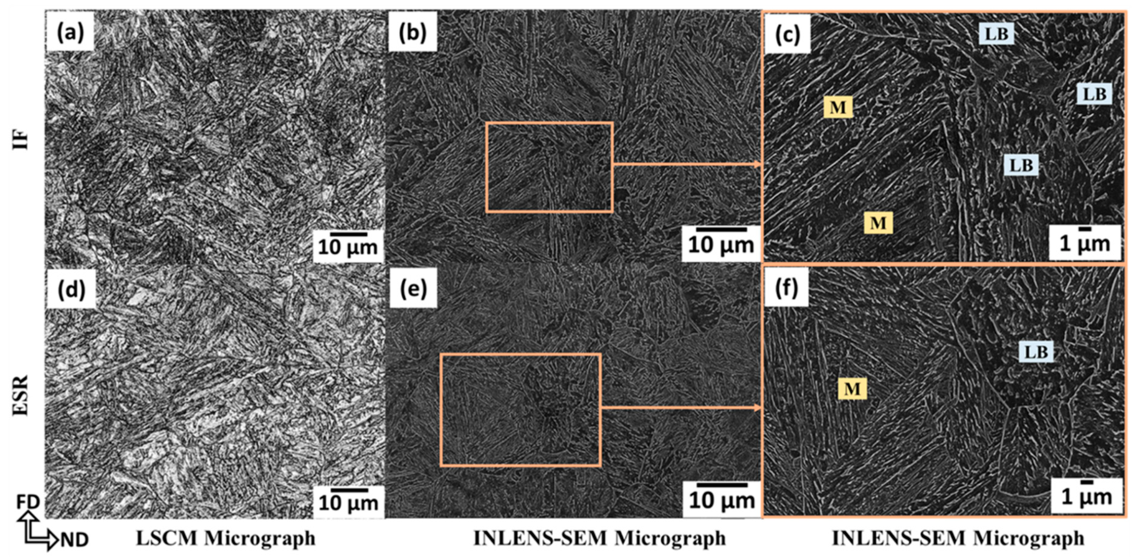
The microstructures of UHSS I, II, and III without and with ESR are shown in Figure 2, Figure 3 and Figure 4, respectively. UHSS I and II are fully martensitic with a very small fraction of precipitates and small fractions of RA. The same is true of UHSS III except it could also be qualitatively seen to contain a large fraction of lower bainite. The volume fraction of bainite is increased from 54 ± 3% with a microhardness 435 ± 3 to 66 ± 2% with a microhardness 437 ± 7 as a result of ESR while the microhardness of the martensite slightly increased from 506 ± 5 to 518 ± 5. The measurements are based on the use of Image J software and the different responses of martensite and bainite to color etching.
Table 2 shows that the fractions of RA determined using XRD were in the range of 5–8%. ESR led to an increase in the case of UHSS I but a decrease in the case of UHSS II and III, presumably because of the small changes in the chemical compositions. The calculated Cγ was reduced as a result of ESR in both the fully martensitic steels, UHSS I and II. However, it remained unchanged in the martensitic–bainitic steel, UHSS III.
LSCM micrographs showing the prior austenite grain structure of the steels are shown in Figure 5 and the PAGS are given in Table 2. The mean PAGS was halved with ESR in the martensitic UHSS I and II. However, in the case of the martensitic-bainitic UHSS III, there was no statistically significant change in the PAGS as a result of ESR.
The differences in the microstructures are due to the differences in the chemical compositions and the observations are in line with the predictions of JMatPro software [27] for the current PAGS and cooling rate of 0.3 °C/s, see Table 3. For UHSS I and II, the software predicted 99% martensite and 1% RA for the composition without the ESR treatment. However, for the composition with ESR JMatPro software predicted 95% and 98% martensite, 4% and 1% bainite, and 1% RA for UHSS I and II, respectively. In the case of UHSS III, JMatPro software predicted 91% martensite, 8% bainite and 1% RA for the composition without the ESR treatment and 75% martensite, 24% bainite, and 1% RA for the leaner composition after ESR. ESR is predicted to lead to an increase in the fraction of bainite, as was observed experimentally even though the actual observed fractions of bainite were considerably higher than the predicted ones. Table 3 shows that the estimated transformation temperatures for the chemical compositions before and after ESR are very close apart from the bainite start temperature Bs in UHSS III, which increased from 426 to 438.
It is well known that most of the alloying elements lead to a decrease in the bainite start temperature (BS) as indicated by the following empirical formula, for example [28].
BS = 630 − 45Mn − 40V − 35Si − 30Cr − 25Mo − 20Ni − 15W
The concentrations of some of the alloying elements are decreased as a result of oxidation during ESR, which leads to a small increase in BS and the bainite volume fraction for the forged ingots with ESR. Some studies [29,30,31,32] have indicated that the increase in Al content resulting from ESR leads to an acceleration of the bainitic transformation kinetics, an increase in the fraction of bainite and a decrease in the fraction RA.
Comparing the data in Table 2 and Table 3 shows that the JMatPro software was unable to predict the volume fractions of RA, which were considerably higher than predicted.
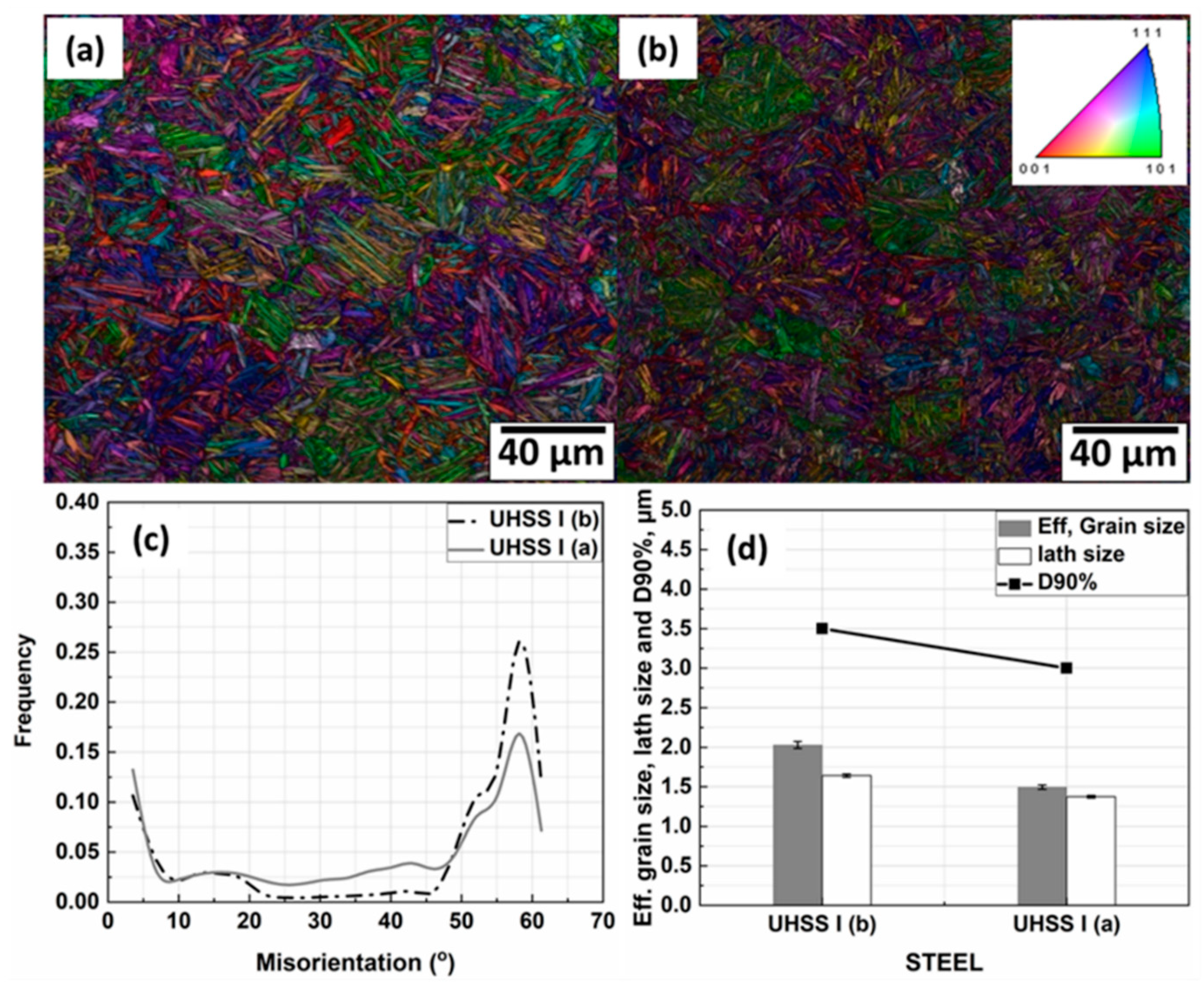
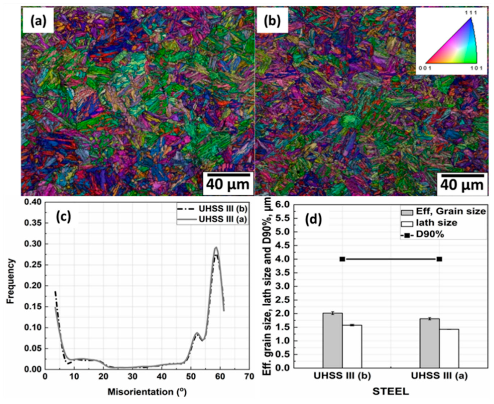
Figure 6a–d, Figure 7a–d, and Figure 8a–d show EBSD inverse pole figure (IPF) combined with image quality (IQ) maps, grain boundary misorientation distributions, lath sizes, effective grain sizes and effective grain sizes at 90% in the cumulative grain size distribution (D90%) for all the steels processed without and with ESR.
In the case of UHSS I, as shown in Figure 6, there are significant changes in the microstructural features because of ESR. ESR decreased the lath size from 1.64 to 1.37 µm (see Figure 6d), whilst the average effective grain size which determined by high-angle grain boundaries was reduced from 2.03 to 1.50 µm. The value of D90% decreased from 3.5 and 3 µm. All these changes are a result of the sharp decrease in the PAGS brought about by ESR [33,34] via the increased pinning effects of precipitates brought about by ESR as will be discussed below.
For UHSS II, as shown in Figure 7, the halving of the PAGS resulting from ESR is accompanied by a big difference in the effective grain size, lath size and D90%. The lath size was reduced from 1.43 to 1.03 µm as a result of ESR (see Figure 7d), while the mean effective grain size was reduced from 1.70 to 1.06 µm. The values of D90% were measured as 3.2 and 2.5 µm with and without ESR, respectively.
In the case of UHSS III, for which the PAGS was unaffected by ESR, it can be seen from Figure 8 that the microstructural parameters revealed by EBSD were much less affected than in the case of UHSS I and II. There is no variation in the distribution of grain boundary misorientations and only slight variation in the average lath and effective grain sizes because of ESR. The lath size was determined to be 1.58 and 1.42 µm without and with ESR, respectively (see Figure 8d), while the mean effective grain sizes were 2.02 and 1.81 µm. The value of D90% was unchanged by ESR at 4 µm. Overall, the refinement of the austenitic microstructure, the small changes in the chemical composition and the increase of the BS temperature for the ESR treated variant lead to the formation of lower bainite separating the prior austenite grains into smaller regions, which hinder the growth of the martensitic laths [35].

3.2. Volume Fractions, Size, and Frequency of Precipitates

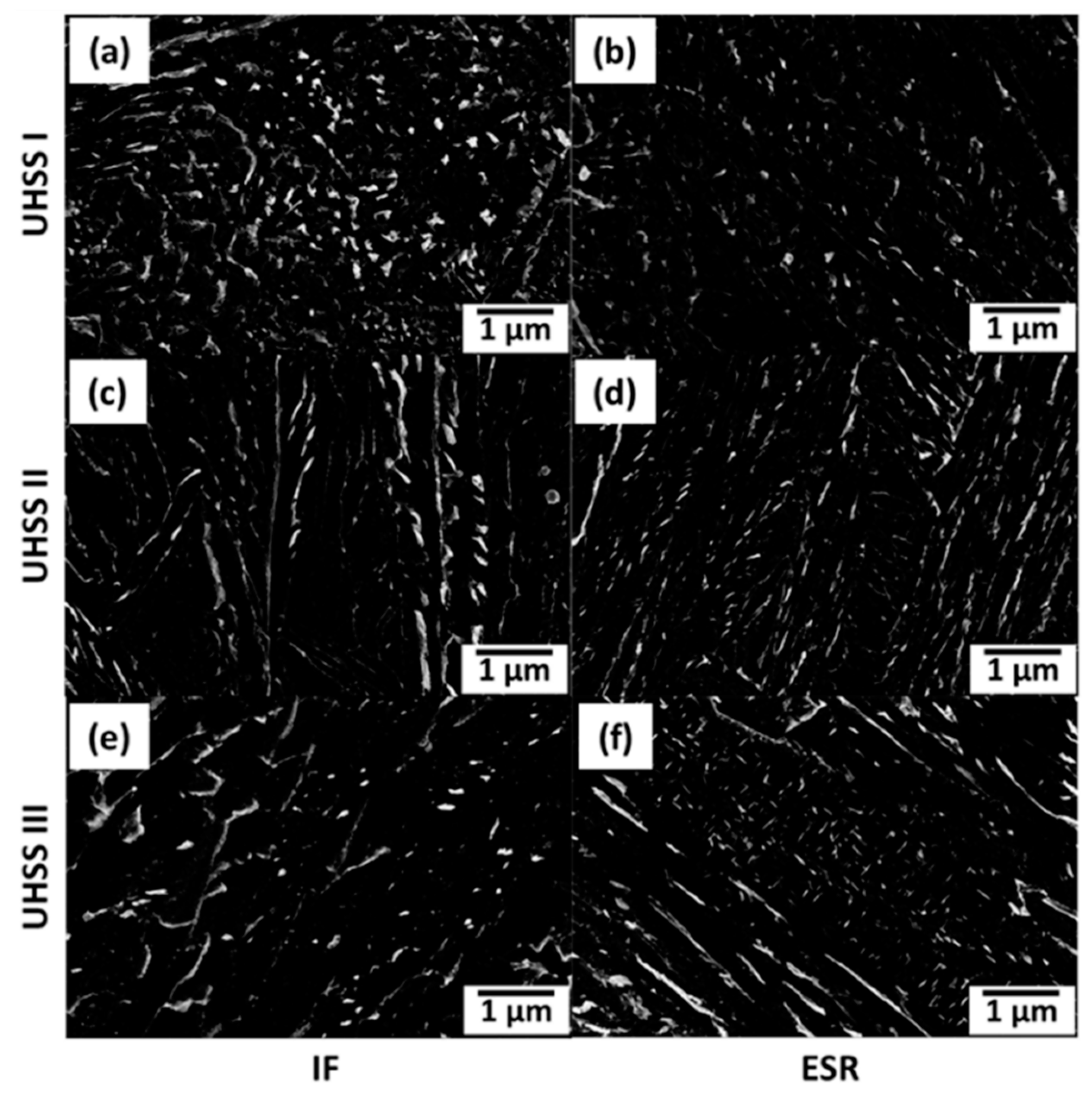
Figure 9 shows typical images of the precipitates in the steels. To investigate the volume fraction, size, and frequency of the precipitates, about 20 INLENS-SEM micrographs at high magnifications covering in total about 588 µm2 were examined for each of the six steels. Image J software was used to calculate the numbers and sizes of all precipitates. Equivalent circle diameter (ECD) was used to characterize the particle size, and the volume fractions of the precipitates were calculated using the following equation [14]:
f = N 4 π 3 ( D p 2 ) 3 S 0 D p = N π D p 2 6 S 0 = 2 N S 3 S 0
where N is the number of particles per investigated area, So the total area analyzed, and S the particle area.
Table 4 summarizes the effect of ESR on the precipitate characteristics, i.e., the volume fractions, the number density, the average size, the 95th percentiles in the cumulative size distribution (D95%), and the maximum size. The number of precipitates increased as a result of ESR in all the steels, i.e., by 29%, 56%, and 40% in UHSS I, II, and III, respectively. Moreover, the volume fractions are increased by 4%, 40%, and 45%. This is presumably a result of an increase in the content of carbon content of the steels brought about by the ESR treatment. However, the average size, maximum size, and D95% of the precipitates are decreased as a result of ESR in all the investigated steels. The appearance of the precipitates and their volume fractions is consistent with their formation via the transformation of austenite to bainite and the auto-tempering of martensite. As discussed below, only small volume fractions of precipitates can form directly from the austenite like AlN, TiN, and VN.
Table 5 shows the volume fractions of different precipitates in equilibrium at 950 and 750 °C and their solvus temperatures as predicted by Thermo-Calc 2017b software with the TCFE7 database. The compositional differences between the steels, especially the large increase in the Al content in the steels with ESR, result in clear differences in the predicted equilibrium volume fractions and types of the precipitates at 950 and 750 °C.
The large increase in the solvus temperatures of AlN, TiN, and VN which become higher than the forging temperatures range (1100–950 °C) brought by ESR is due to the change in chemical composition and is associated with a small increase in the volume fractions of these precipitates at the temperatures considered in Table 5. Moreover, during forging (1100–950 °C), there should be a driving force for more precipitation of AlN, TiN, and VN. After forging, at 750 °C there will be a driving force for the precipitation of different precipitates based on the steel chemical composition (see Table 5).
Figure 10 shows the correlation between the predicted equilibrium volume fractions of precipitates in the investigated steels without and with ESR formed during solidifications of the ingots and cooling through the forging temperature range 1100–950 °C. It seems that the slight increase in the predicted equilibrium volume fractions of AlN, TiN, and VN at the forging finish temperature may be related to the decrease in the PAGS, which is also the main reason behind the refinement of the other microstructure features.

3.3. Effect of ESR on Micro-Segregation

There is always some segregation of the alloying elements in steel ingots produced via ESR due to the inter-dendritic elemental enrichment, which generally has a detrimental effect on the mechanical properties of the cast and forged products [36]. Arh et al. [33] claimed that the higher temperature gradients and cooling rates encountered in ESR lead to finer secondary dendrite arm spacings and less micro-segregation than observed in normally cast steel but, as shown below, such was not the case with the present steels. To evaluate the effect of ESR on the homogeneity of the steel alloy contents, i.e., micro-segregation, in the case of the present steels, the distributions of Cr, W, Mo, Ni, Mn, V, and Si were measured using EPMA. To determine the degree of elemental segregation, the nominal segregation index (ζi) [37,38] was calculated using the following equation, and the results are given in Table 6:
ζ i = C o i / C i n t e r d e n d r i t i c i
where C o i is the nominal concentration of the alloying elements listed in Table 1 and C i n t e r d e n d r i t i c i is the concentration of the alloying elements measured in the interdendritic area. Moreover, IDS software [39] was used to predict the degree of segregation by determining the nominal segregation index and given in Table 6. However, unfortunately, it is not possible to calculate the nominal segregation index for W because it is not included in the IDS software.
Table 6 shows that there is no significant effect of ESR on the segregation of the alloying elements. Presumably, the effect of the smaller secondary dendrite arm spacings, i.e., smaller diffusion distances, is counteracted by the shorter diffusion times that result from the higher cooling rates. Table 6 also indicates that, in many cases, the IDS software is able to predict segregation indices that are close to the experimentally measured values.

3.4. Mechanical Properties

Table 7 summarizes the mechanical properties of all investigated UHSS with and without ESR. As can be seen, there are no simple trends resulting from ESR. This is to be expected as the mechanical properties are a complex result of the combined influence of chemical composition and processing parameters on the final microstructure as discussed below. In addition to microstructure, inclusion cleanliness is also important from the point of view of toughness.
Different contributions to yield strength, such as the contribution from lath refinement strengthening (σL), precipitation strengthening (σp), and dislocation density strengthening (σD), have been calculated and the results are given in Table 8. The lath refinement strengthening was estimated from Equation (4) [40]. However, in order to use Equation (4), the magnitudes of the lath sizes were converted from ECD to mean linear intercept (MLI) with the aid of Equation (5) [41] and both values are given in Table 9. The precipitation strengthening contribution (σp) was calculated using Equation (6), i.e., the Ashby–Orowan equation, [42].
σ L ( M P a ) = 115 / d L
where dL is the lath size in µm.
E C D = 4 π M L I
σ p = ( 12.2 f D ) ln ( 1630 D )
where f is the volume fraction of precipitates and D is the precipitate diameter in nm.
Dislocation density (ρ) and its contribution to strengthening (σD) have been calculated using Equations (7) and (8) [43,44]:
ρ × 10 15 = 0.7 + 3.5 wt . %
σ D = α G b ρ 1 2
Here α is a constant equal to 0.24, G is the shear modulus (80 GPa), and b is the Burgers vector (0.25 nm).

3.4.1. Changes in the Mechanical Properties of UHSS I

In UHSS I, as a result of ESR tensile strength, yield strength and hardness are increased by 106 MPa (6%), 132 MPa (12%), and 47 HV (9%). The differences in the elongation to fracture and CVN impact toughness were not significant at the 95% confidence level according to Student’s t-test analyses.
The increase in the UTS, YS, and hardness may be attributed to several parameters which are interrelated, and it is very difficult to separate the effect of these parameters from each other. The slight increase in the carbon content from 0.30% to 0.32% as a result of ESR might be one of the reasons for strengthening the martensite and increasing the strength and hardness values. The high cooling rate of ESR indirectly leads to solution hardening and increases the strength and hardenability by decreasing the size of precipitates through inhibition of alloying elements diffusion and increasing the dissolution of alloying elements in the matrix. Moreover, refinement of the PAGS, effective grain size, and lath size from 25, 2.03 and 1.64 to 13, 1.5 and 1.37 µm will contribute to increasing the strength and hardness values. The refinement of the PAGS may be due to the presence of AlN and TiN precipitates which formed during the forging process, as discussed above. These could produce Zener pinning effects that hinder the growth of the PAG. Further, an increase in the RA % may contribute to increasing the ultimate tensile strength as a result of its transformation to martensite as a result of the TRIP effect. In addition to the microstructure refinement and precipitation strengthening, the dislocation density will contribute to increasing the yield strength via dislocation strengthening mechanism. The incremental contributions to the yield strength as a result of ESR from σL, σp, and σD were estimated to be 23, 1 and 4 MPa, respectively (see Table 8). The remaining 104 MPa from the total improvement of the yield strength caused by ESR presumably results from the slight increase in carbon content from 0.30% to 0.32% and the great refinement in the PAGS and the effective grain size. Increases in the yield strength of martensite have been attributed to both finer PAGS [8] and effective grain size (block size) [46]. Moreover, increases in the yield and tensile strength of bainite have been attributed to the refinement of PAGS, packet size, and block size [47]. As suggested by Hutchinson et al. [48], most of the strength of martensite is probably due to segregated carbon atoms. It is possible, therefore, that the majority of the differences in strength in the present case is due to the small increase in carbon content from 0.30% to 0.32%.
Despite the large increase in the UTS, YS and hardness, the elongation and impact toughness have the same or slight increase and there is a slight increase in the percentage of ductile fracture from 30% to 34% as a result of ESR. This return to the high degree of refining with ESR as observed in our previously published work [19] in which the total impurity level reduced with ESR by 46%. Moreover, removal of most MnS, which has the most detrimental effects on toughness and ductility and some of them are nucleate and grow on some oxide or nitride inclusions leading to smaller size multiphase inclusions with an oxide or nitride core surrounded by sulfide, e.g., (MnS·Al2O3), (MnS·TiN·Al2O3), (MnS·CaO·Al2O3), (MnS·TiO2), (MnS·TiN), (MnS·(TiV)N), and (MnS·TiON) with the modified (Ca·Mn) S and CaS·Al2O3. These formed NMIs have more resistance to deformation than MnS, which also enhances the impact toughness. Moreover, removal of low deformability index, hard and large oxides inclusions occupying large area fractions in UHSS I without ESR like (Al2O3·SiO2), (MnO·Al2O3·SiO2), (MnO·SiO2), (CaO·MnO·Al2O3·SiO2), (MnS·Al2O3·SiO2), (MnS·SiO2) or converted to other modified inclusions with a lower melting point such as xCaO·yAl2O3 is the main reason to prevent deterioration of the impact toughness and elongation to fracture properties. Moreover, decreasing the effective grain size leads to increasing the large angle boundaries that the crack needs to pass through, which leads to increasing the energy required and, hence, enhancing or preventing deterioration in the impact toughness properties.
However, the insignificant effect of ESR on increasing impact toughness in the case of UHSS I may be the result of increasing the Al content by 85% and the area fraction of Al2O3 particles by 95% with ESR as a result of the Al deoxidant added at the beginning of the experiment. Moreover, the presence of titanium nitride inclusion with ESR in the complex multiphase inclusions, e.g., (TiV)N·(MnS·TiN·Al2O3), (MnS·TiN), (MnS·(TiV)N), (TiN·Al2O3), and (TiON·MnS) can be one of the reasons which prevent increasing the impact toughness despite the high degree of refining in the microstructure features because the TiN inclusions are characterized by large blocky cubic morphology and cracks initiate easily at its sharp corner or in the TiN particles itself because of its brittleness [49]. Cox and Low [50] concluded that decreasing the number and size of NMIs of 4340 steels can not only increase the void nucleation resistance but also improve its toughness properties.

3.4.2. Changes in the Mechanical Properties of UHSS II

In UHSS II, UTS increased substantially after ESR by 278 MPa (16%), YS increased by 63 MPa (5%), and hardness by 30 HV (6%). However, elongation to fracture and CVN impact toughness are deteriorated by four percentage points (22%) and 9 J (25%), respectively. The calculated strengthening contributions from laths, precipitates, and dislocations (see Table 8) show an expected increment in the yield strength of about 91 MPa, which is close to the actual increase of 63 MPa. The deterioration in elongation to fracture and CVN impact toughness are natural consequences of the increase in UTS, probably in combination with the appearance of Al2O3 inclusions.

3.4.3. Changes in the Mechanical Properties of UHSS III

Unlike the expected increment in the strength and hardenability as a result of ESR, major differences in the mechanical properties of UHSS III with ESR, as UTS, YS, and hardness are decreased by 88 MPa (7%), 90 MPa (10%), and 25 HV (6%), respectively. However, elongation to fracture and CVN impact toughness are enhanced by two percentage points (11%) and 14 J (26%).
The main reason for decreasing the tensile properties and hardness are the increasing of the volume fraction of bainite from 54% to 66% with ESR due to the slight change in the chemical composition which leads to increase the bainite start temperature from 428 to 439 °C, as calculated using JMatPro software using the chemical composition without and with ESR.
Enhancement in the elongation and impact toughness returned to the refinement of the bainitic and martensitic structure as the effective grain size and lath sizes were reduced from 2.02 to 1.81 µm and from 1.58 to 1.42 µm, respectively, as a result of ESR and the presence of AlN and TiN precipitates at high temperatures. Reducing the size of the effective (high angle grain boundary) grain size of the martensitic structure leads to increasing the work needed to propagate the initiated cracks across its high angle grain boundaries as a result of changing the crystallographic orientation and the crack direction when cracks start to propagate across the high angle boundary [51]. The increasing high angle boundaries are confirmed by the slight increase in the peak of misorientation at 58°. This may arrest the local cleavage crack, which starts to require more load to overcome these barriers before the final failure [52]. This behavior leads to increased impact toughness.

3.5. Fractography

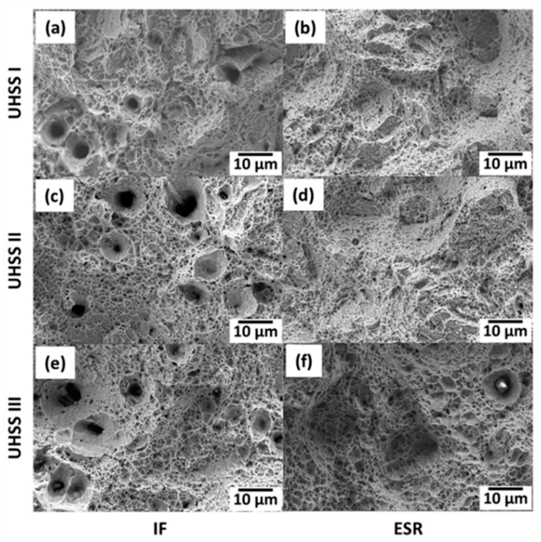
Figure 11 shows fractographs of selected areas from broken tensile test specimens. The fracture surfaces show the dimples characteristic of the microvoid coalescence associated with ductile fracture. Without ESR, Figure 11a–c reveals the presence of large voids, which are due to the presence of large NMIs with ECDs ranging from 8 to 10 µm, as observed in our previously published work [19]. However, after ESR, the frequency and sizes of the NMIs are reduced, which is seen as a lower incidence of large voids in the fracture surfaces in Figure 11d–f.

4. Conclusions

Three ultrahigh-strength steels containing different amounts of Cr, Ni, Mo, W, Mn, and V have been melted in an induction furnace and then refined using ESR technology with a slag based on CaF2. A detailed investigation of bars forged, and air cooled from the induction melted ingots and the ESR ingots has been made. This included characterization of the microstructural components present, PAGS, effective grain, and lath sizes, number and size of precipitates, and degree of micro-segregation together with tensile and Charpy V impact testing. The following conclusions can be drawn.
  • ESR leads to refinement of the PAGS in all of the investigated steels.
  • ESR has almost no effect on the degree of micro-segregation.
  • It is not possible to draw general conclusions regarding the effect of ESR on the NMI characteristics, microstructure, and mechanical properties. The effect depends on the impurity level, the starting chemical composition, and the change in chemical composition during ESR, together with the composition of the slag and the details of the subsequent thermomechanical treatment.
  • For the fully martensitic steels studied, ESR leads to an increase in the UTS, YS, and hardness. Many microstructural features have been identified that can contribute to the improvement of these properties: Refinement of the PAGS, the effective high-angle grain size, and the lath size, an increase in the number of fine precipitates, and an increase in RA. However, for the fully martensitic steels, the effect of ESR on elongation to fracture, CVN impact toughness, and percentage ductile fracture varies with the steel chemistry.
  • For the steel with a mixed martensitic–bainitic microstructure, the changes in chemical composition brought about by ESR led to an increase in the volume fraction of bainite, which lowered the UTS and YS, but enhanced the elongation to fracture, the CVN impact toughness, and the percentage ductile fracture.
  • The reduction in the size and incidence of NMIs brought about by ESR leads to a reduction in the incidence of large microvoids on the ductile fracture surfaces of room temperature tensile test specimens.

Author Contributions

Writing—review and editing, M.A. and D.P.; supervision, D.P., J.K., M.E., T.M. and H.E.F. All authors have read and agreed to the published version of the manuscript.

Funding

This research was funded by the Egyptian Ministry of Higher Education (Cultural Affairs and Missions Sector) and the APC was funded by Materials and Mechanical Engineering Department, University of Oulu, Oulu, Finland.

Acknowledgments

The authors acknowledge the Egyptian Ministry of Higher Education (Cultural Affairs and Missions Sector) for financial support during this work.

Conflicts of Interest

The authors declare no conflict of interest.

References

  1. Gladman, T. The Physical Metallurgy of Microalloyed Steels; Institute of Materials: London, UK, 1997. [Google Scholar]
  2. Bhattacharya, A.; Singh, P.M. Effect of Heat Treatment on Corrosion and Stress Corrosion Cracking of S32205 Duplex Stainless Steel in Caustic Solution. Metall. Mater. Trans. A 2009, 40, 1388–1399. [Google Scholar] [CrossRef]
  3. Maity, S.K.; Rajak, A.K.; Chandra Shekhar, M.; Singh, S.D. Development of 0.2 C-CrMnMoV Ultra High Strength Steel. Int. J. Sci. Eng. Technol. 2014, 3, 101–108. [Google Scholar]
  4. Maity, S.K.; Ballal, N.B.; Goldhahn, G.; Kawalla, R. Development of Ultrahigh Strength Low Alloy Steel through Electroslag Refining Process. ISIJ Int. 2009, 49, 902–910. [Google Scholar] [CrossRef] [Green Version]
  5. Caballero, F.G.; Bhadeshia, H.K.D.H. Very strong bainite. Curr. Opin. Solid State Mater. Sci. 2004, 8, 251–257. [Google Scholar] [CrossRef] [Green Version]
  6. Garcia-Mateo, C.; Caballero, F.G.; Bhadeshia, H.K.D.H. Development of Hard Bainite. ISIJ Int. 2003, 43, 1238–1243. [Google Scholar] [CrossRef] [Green Version]
  7. Yokota, T.; García Mateo, C.; Bhadeshia, H.K.D.H. Formation of nanostructured steels by phase transformation. Scr. Mater. 2004, 51, 767–770. [Google Scholar] [CrossRef] [Green Version]
  8. Kennett, S.C.; Findley, K.O. Strengthening and toughening mechanisms in martensitic steel. Adv. Mater. Res. 2014, 922, 350–355. [Google Scholar] [CrossRef]
  9. Morito, S.; Tanaka, H.; Konishi, R.; Furuhara, T.; Maki, T. The morphology and crystallography of lath martensite in Fe-C alloys. Acta Mater. 2003, 51, 1789–1799. [Google Scholar] [CrossRef]
  10. Kitahara, H.; Ueji, R.; Tsuji, N.; Minamino, Y. Crystallographic features of lath martensite in low-carbon steel. Acta Mater. 2006, 54, 1279–1288. [Google Scholar] [CrossRef]
  11. Zhang, L.P.; Davis, C.L.; Strangwood, M. Effect of TiN particles and microstructure on fracture toughness in simulated heat-affected zones of a structural steel. Metall. Mater. Trans. A 1999, 30, 2089–2096. [Google Scholar] [CrossRef]
  12. Wang, C.; Wang, M.; Shi, J.; Hui, W.; Dong, H. Effect of microstructure refinement on the strength and toughness of low alloy martensitic steel. J. Mater. Sci. Technol. 2007, 23, 659–664. [Google Scholar]
  13. Orowan, E. Discussion in on Internal Stresses. In Symposium on Internal Stresses in Metals and Alloys; Institute of Metals: London, UK, 1947. [Google Scholar]
  14. Wang, Q.; Zhang, C.; Li, R.; Gao, J.; Wang, M.; Zhang, F. Characterization of the microstructures and mechanical properties of 25CrMo48V martensitic steel tempered at different times. Mater. Sci. Eng. A 2013, 559, 130–134. [Google Scholar] [CrossRef]
  15. Vaish, A.K.; Iyer, G.V.R.; De, P.K.; Lakra, B.A.; Chakrabarti, A.K.; Ramachandrarao, P. Electroslag remelting-Its status, mechanism and refining aspects in the production of quality steels. J. Metall. Mater. Sci. 2000, 42, 11–29. [Google Scholar]
  16. Duckworth, W.E.; Hoyle, G. Electroslag Refining; Chapman and Hall: London, UK, 1969. [Google Scholar]
  17. Biebricher, U.; Scholz, H. Electro slag remelting technologies in the past and in the future. Plant Technol. Int. (Germany) 1998, 22, 36–38. [Google Scholar]
  18. Zhu, Q.; Li, J.; Shi, C.; Yu, W. Effect of electroslag remelting on carbides in 8Cr13MoV martensitic stainless steel. Int. J. Miner. Metall. Mater. 2015, 22, 1149–1156. [Google Scholar] [CrossRef]
  19. Ali, M.; Porter, D.; Kömi, J.; Heikkinen, E.P.; Eissa, M.; El, F.; Mattar, T. The effect of electroslag remelting on the cleanliness of CrNiMoWMnV ultrahigh-strength steels. J. Min. Metall. Sect. B 2019, 55, 381–395. [Google Scholar] [CrossRef] [Green Version]
  20. Ali, M.; Eissa, M.; El Faramawy, H.; Porter, D.; Kömi, J.; El-Shahat, M.F.; Mattar, T. Electroslag Refining of CrNiMoWMnV Ultrahigh-Strength Steel. J. Miner. Mater. Charact. Eng. 2017, 5, 385. [Google Scholar] [CrossRef] [Green Version]
  21. Meng, F.G.; Dong, J.X.; Zhang, M.C. Comparison of microstructure characteristics of different smelting process in 028 alloy for oil pipes. Mater. Res. Innov. 2014, 18, S4-301–S4-308. [Google Scholar] [CrossRef]
  22. Wang, C.; Wang, M.; Shi, J.; Hui, W.; Dong, H. Effect of microstructural refinement on the toughness of low carbon martensitic steel. Scr. Mater. 2008, 58, 492–495. [Google Scholar] [CrossRef]
  23. Apple, C.A.; Caron, R.N.; Krauss, G. Packet microstructure in Fe-0.2 pct C martensite. Metall. Trans. 1974, 5, 593–599. [Google Scholar] [CrossRef]
  24. Krauss, G. Martensite in steel: Strength and structure. Mater. Sci. Eng. A 1999, 273–275, 40–57. [Google Scholar] [CrossRef]
  25. Zakerinia, H.; Kermanpur, A.; Najafizadeh, A. Color metallography; a suitable method for characterization of martensite and bainite in multiphase steels. Int. J. Iron Steel Soc. Iran 2009, 6, 14–18. [Google Scholar]
  26. Dyson, D.J.; Holmes, B. Effect of alloying additions on the lattice parameter of austenite. J. Iron Steel Inst. 1970, 208, 469–474. [Google Scholar]
  27. Schillé, J.-P.; Guo, Z.; Saunders, N.; Miodownik, A.P. Modeling phase transformations and material properties critical to processing simulation of steels. Mater. Manuf. Processes 2011, 26, 137–143. [Google Scholar] [CrossRef]
  28. Zhao, Z.; Liu, C.; Liu, Y.; Northwood, D.O. A new empirical formula for the bainite upper temperature limit of steel. J. Mater. Sci. 2001, 36, 5045–5056. [Google Scholar] [CrossRef]
  29. Bleck, W.; Kechagias, E.; Ohlert, J.; Christen, J.L.; Moulin, A.; Haidemenopoulos, G.; Vasilakos, A.; Katsamas, A.; Papatriantafyllou, G.; Aaravas, N. Optimisation of Microstructure in Multiphase steels containing retained austenite. EUR 2004, 21131, 1–199. [Google Scholar]
  30. De Cooman, B.C. Structure–properties relationship in TRIP steels containing carbide-free bainite. Curr. Opin. Solid State Mater. Sci. 2004, 8, 285–303. [Google Scholar] [CrossRef]
  31. Traint, S.; Pichler, A.; Hauzenberger, K.; Stiaszny, P.; Werner, E. Influence of silicon, aluminium, phosphorus and copper on the phase transformations of low alloyed TRIP-steels. Steel Res. Int. 2002, 73, 259–266. [Google Scholar] [CrossRef]
  32. Papaefthymiou, S.; Bleck, W.; Kruijver, S.; Sietsma, J. Influence of intercritical deformation on microstructure of TRIP steels containing Al. Mater. Sci. Technol. 2004, 20, 201. [Google Scholar]
  33. Arh, B.; Podgornik, B.; Burja, J. Electroslag remelting: A process overview. Mater. Sci. Technol. 2016, 50, 971–979. [Google Scholar] [CrossRef]
  34. Kawalla, R. Development of ultrahigh strength steel by electroslag refining: Effect of inoculation of titanium on the microstructures and mechanical properties. ISIJ Int. 2006, 46, 1361–1370. [Google Scholar]
  35. Zhou, T.; Yu, H.; Wang, S. Effect of microstructural types on toughness and microstructural optimization of ultra-heavy steel plate: EBSD analysis and microscopic fracture mechanism. Mater. Sci. Eng. A 2016, 658, 150–158. [Google Scholar] [CrossRef]
  36. Man, J.; Yang, Y.T.; Shao, G.J. The Microstructure and Elements Distribution of High-Chiromium Hypereatectoid Steel by High-Temperature Homogenization. Available online: https://www.scientific.net/AMR.652-654.975 (accessed on 11 May 2018).
  37. D’Souza, N.; Lekstrom, M.; Dong, H.B. An analysis of measurement of solute segregation in Ni-base superalloys using X-ray spectroscopy. Mater. Sci. Eng. A 2008, 490, 258–265. [Google Scholar]
  38. Wang, M.; Zha, X.; Gao, M.; Ma, Y.; Liu, K.; Li, Y. Structure, Microsegregation, and Precipitates of an Alloy 690 ESR Ingot in Industrial Scale. Metall. Mater. Trans. A 2015, 46, 5217–5231. [Google Scholar] [CrossRef]
  39. Miettinen, J.; Louhenkilpi, S.; Kytönen, H.; Laine, J. IDS: Thermodynamic–kinetic–empirical tool for modelling of solidification, microstructure and material properties. Math. Comput. Simul. 2010, 80, 1536–1550. [Google Scholar] [CrossRef]
  40. Simm, T.; Sun, L.; McAdam, S.; Hill, P.; Rawson, M.; Perkins, K. The Influence of Lath, Block and Prior Austenite Grain (PAG) Size on the Tensile, Creep and Fatigue Properties of Novel Maraging Steel. Materials 2017, 10, 730. [Google Scholar] [CrossRef] [Green Version]
  41. Roebuck, B.; Phatak, C.; Birks-Agnew, I. A Comparison of the Linear Intercept and Equivalent Circle Methods for Grain Size Measurement in WC/Co Hardmetals; NPL Report: Middlesex, UK, 2004. [Google Scholar]
  42. Mandal, G.; Roy, C.; Ghosh, S.K.; Chatterjee, S. Structure-property relationship in a 2 GPa grade micro-alloyed ultrahigh strength steel. J. Alloys Compd. 2017, 705, 817–827. [Google Scholar] [CrossRef]
  43. Morito, S.; Nishikawa, J.; Maki, T. Dislocation density within lath martensite in Fe-C and Fe-Ni alloys. ISIJ Int. 2003, 43, 1475–1477. [Google Scholar] [CrossRef] [Green Version]
  44. Hansen, N.; Huang, X. Microstructure and flow stress of polycrystals and single crystals. Acta Mater. 1998, 46, 1827–1836. [Google Scholar] [CrossRef]
  45. Haynes, A.G.; Steven, W. The temperature of formation of martensite and bainite in low-alloy steel. J. Iron Steel Inst. 1956, 183, 349–359. [Google Scholar]
  46. Sun, X.; Li, Z.; Yong, Q.; Yang, Z.; Dong, H.; Weng, Y. Third generation high strength low alloy steels with improved toughness. Sci. China Technol. Sci. 2012, 55, 1797–1805. [Google Scholar] [CrossRef]
  47. Lan, H.F.; Du, L.X.; Li, Q.; Qiu, C.L.; Li, J.P.; Misra, R.D.K. Improvement of strength-toughness combination in austempered low carbon bainitic steel: The key role of refining prior austenite grain size. J. Alloys Compd. 2017, 710, 702–710. [Google Scholar] [CrossRef]
  48. Hutchinson, B.; Hagström, J.; Karlsson, O.; Lindell, D.; Tornberg, M.; Lindberg, F.; Thuvander, M. Microstructures and hardness of as-quenched martensites (0.1–0.5%C). Acta Mater. 2011, 59, 5845–5858. [Google Scholar] [CrossRef]
  49. Xie, X.S.; Zeng, Y.P. The effect of inclusions on mechanical behaviour in ultra-high strength alloy steels. Mater. Sci. Forum 2010, 654, 51–56. [Google Scholar] [CrossRef]
  50. Cox, T.B.; Low, J.R. An investigation of the plastic fracture of AISI 4340 and 18 Nickel-200 grade maraging steels. Metall. Trans. 1974, 5, 1457–1470. [Google Scholar] [CrossRef]
  51. Zhou, Q.; Qian, L.; Tan, J.; Meng, J.; Zhang, F. Inconsistent effects of mechanical stability of retained austenite on ductility and toughness of transformation-induced plasticity steels. Mater. Sci. Eng. A 2013, 578, 370–376. [Google Scholar] [CrossRef]
  52. Tu, M.-Y.; Hsu, C.-A.; Wang, W.-H.; Hsu, Y.-F. Comparison of microstructure and mechanical behavior of lower bainite and tempered martensite in JIS SK5 steel. Mater. Chem. Phys. 2008, 107, 418–425. [Google Scholar] [CrossRef]
Figure 1. Location and orientation of samples in the forged bars. Samples 1 and 2 tensile specimens, 3 and 4 impact specimens, 5 and 6 microstructures, NMI, and HV10 and 7 XRD.
Metals 10 00262 g001
Figure 2. Laser and INLENS-SEM micrographs of UHSS I (IF) without ESR (ac) and with ESR (df). M: Martensite and ATM: auto-tempered martensite.
Metals 10 00262 g002
Figure 3. Laser and INLENS-SEM micrographs of UHSS II (IF) without ESR (ac) and with ESR (df). M: martensite and ATM: auto-tempered martensite.
Metals 10 00262 g003
Figure 4. Laser and INLENS-SEM micrograph of UHSS III (IF) without ESR (ac) and with ESR (df). M: Martensite and LB: Lower bainite.
Metals 10 00262 g004
Figure 5. LSCM micrograph of PAG of forged and air-cooled bars of UHSS I, II, and III without ESR (a,c,e) and with ESR (b,d,f).
Metals 10 00262 g005
Figure 6. IPF with superimposed IQ map of forged and air-cooled bar of UHSS I without ESR (a) and with ESR (b) (scale bar is 40 µm), grain boundary misorientations (c), mean lath size, mean effective grain size and D90% (d).
Metals 10 00262 g006
Figure 7. IPF with superimposed IQ map of forged and air-cooled bar of UHSS II without ESR (a) and with ESR (b) (scale bar is 40 µm), grain boundary misorientations (c), mean lath size, mean effective grain size and D90% (d).
Metals 10 00262 g007
Figure 8. IPF with superimposed IQ map of forged and air-cooled bar of UHSS III without ESR (a) and with ESR (b) (scale bar is 40 µm), grain boundary misorientations (c), mean lath size, mean effective grain size and D90% (d).
Metals 10 00262 g008
Figure 9. INLENS-SEM micrographs for precipitates of UHSS I, II and III without ESR (a,c,e) and with ESR (b,d,f).
Metals 10 00262 g009
Figure 10. Correlation between the predicted equilibrium volume fraction of nitrides at the forging finish temperature (950 °C) and the PAGS without (b) and with (a) ESR.
Metals 10 00262 g010
Figure 11. SEM micrograph of fracture surface of tensile test specimens in UHSS I, II, and III without ESR (a,c,e) and with ESR (b,d,f), respectively.
Metals 10 00262 g011
Table 1. Chemical composition of the investigated steels without and with effect of electroslag remelting (ESR) in wt.%.
Heat No.ProcessChemical Composition, wt.%
CCrNiMoWMnSiVTiNbCuAlPSNO
UHSS IIF0.302.322.340.321.210.700.710.0750.0010.0010.0170.0090.0190.0240.0130.014
ESR0.322.182.310.311.140.640.640.0720.0010.0010.0200.0600.0180.0130.0110.004
UHSS IIIF0.252.402.490.321.340.570.900.0870.0020.0010.0180.0090.0190.0250.0200.011
ESR0.292.372.450.331.230.530.810.0850.0030.0010.0200.0580.0190.0140.0180.007
UHSS IIIIF0.151.734.440.311.330.410.510.0670.0020.0020.0160.0090.0180.0220.0220.012
ESR0.181.654.350.321.240.350.310.0620.0010.0010.0200.0430.0180.0170.0150.006
IF: Induction furnace ingots, ESR: Electroslag remelting ingots.
Table 2. Volume and carbon percentage of RA and PAGS in UHSS I, II, and III without and with ESR.
Heat No.ProcessVol. Fraction of RA, % 1Mean % C in RA (Cγ)Mean PAGS, µm 2
UHSS IIF5.2 ± 0.30.725 ± 2.8
ESR6.5 ± 0.10.413 ± 1.7
UHSS IIIF8.1 ± 0.21.227 ± 3.2
ESR6.6 ± 0.10.413 ± 2.1
UHSS IIIIF7.1 ± 0.20.823 ± 2.7
ESR5.6 ± 0.80.822 ± 3.1
1 Error bars are the standard deviation of the population. 2 Error bars are 95 % confidence intervals for the mean.
Table 3. Results from simulations of the CCT behavior of the composition of UHSS I, II and III without and with ESR using JMatPro software [27].
SteelProcessVol. Fraction of Bainite, %Vol. Fraction of Martensite, %Vol. Fraction of RA, %Bainite Start Temperature (Bs), °CMartensite Start Temperature (Ms), °C
UHSS IIF0991388280
ESR4951397279
UHSS IIIF0991384292
ESR1981382284
UHSS IIIIF8911426313
ESR24751438314
Table 4. Characteristics of precipitates in UHSS I, II and III without and with ESR.
SteelProcessVolume Fraction of Precipitates (f), %Number of Precipitates per Total Investigated Area, 588 µm2Average Size, nmD95%, nmMax. Size, nm
UHSS IIF0.371742 (3/µm2)49 ± 0.53120381
ESR0.392239 (4/µm2)44 ± 0.41110321
UHSS IIIF0.411333 (2/µm2)59 ± 0.94170532
ESR0.582078 (4/µm2)56 ± 0.61140498
UHSS IIIIF0.311108 (2/µm2)56 ± 1.00150565
ESR0.451555 (3/µm2)54 ± 0.82140541
Table 5. Solvus temperatures and the volume fractions of precipitates in equilibrium at 950 °C and 750 °C.
SteelTemperature, °CPrecipitatesSolvus Temperature, °CVolume Fractions of Each Precipitates at Given Temperature, %Total Volume Fractions at Given Temperature, %
UHSS I (IF)950AlN10220.01000.064
VN10640.0539
750AlN10220.02502.417
Ti(N,C)7930.0003
VN10640.1100
M23C6 [(Cr,Fe)20 (Mo,W)3 (C)6]8032.2820
UHSS I (ESR)950AlN11860.07030.072
TiN12700.0020
750AlN11860.07502.373
VC9000.1240
M23C6 [(Cr,Fe)20 (Mo,W)3 (C)6]8002.1744
UHSS II (IF)950AlN10480.01400.106
VN11200.0920
750AlN10480.02802.196
V(N,C)11200.1350
Ti(N,C)8040.0006
M23C6 [(Cr,Fe)20 (Mo,W)3 (C)6]7812.0320
UHSS II (ESR)950AlN12240.11300.119
TiN13960.0060
750AlN12240.11802.732
TiN13960.0040
VC9150.1400
M23C6 [(Cr,Fe)20 (Mo,W)3 (C)6]7972.4700
UHSS III (IF)950AlN10690.01900.092
TiN13960.0730
750AlN10690.03100.143
TiN13960.1120
UHSS III (ESR)950AlN11780.09100.093
TiN13050.0020
750AlN11780.10000.170
TiN13050.0010
V(C,N)8530.0690
Table 6. Theoretical and experimental segregation indices (ζi) for the alloying elements.
SteelProcessSiCrWMoNiMnV
UHSS IIDS Calc.0.80.7NA0.31.00.80.4
IF0.80.61.00.40.90.80.4
ESR0.80.60.80.41.00.70.5
UHSS IIIDS Calc.1.10.6NA0.20.91.40.2
IF0.70.61.00.40.90.80.3
ESR0.70.70.80.51.00.70.5
UHSS IIIIDS Calc.0.80.7NA0.30.90.80.4
IF0.70.61.00.51.00.80.5
ESR0.70.71.00.61.00.80.4
Table 7. Tensile properties, Charpy-V notch impact toughness and hardness of investigated UHSS without and with ESR.
SteelProcessTensile PropertiesCharpy V Test at Room TemperatureHardness
Rm, MPaRp0.2, MPaA, %Absorbed Energy, JDuctile 1 Fracture%HV10Calculated Hardness for Full Martensite 2
UHSS IIF1872 ± 14.631145 ± 23.0712 ± 1.3324 ± 0.530548 ± 6558
ESR1978 ± 32.701277 ± 14.1414 ± 0.1525 ± 0.534595 ± 5576
UHSS IIIF1729 ± 6.821153 ± 17.1418 ± 0.1636 ± 0.559532 ± 10514
ESR2007 ± 7.741216 ± 17.2014 ± 0.2527 ± 130562 ± 13549
UHSS IIIIF1353 ± 9.06921 ± 5.4719 ± 0.5853 ± 3.569411 ± 4426
ESR1265 ± 13.08831 ± 19.9921 ± 0.5267 ± 2.572386 ± 3452
1 Ductile fracture % was calculated according to ASTM A 370-11. 2 The hardness values for full martensitic structure have been calculated using the following equation [45]: HV (martensite) = 884C − (1 − 0.3C2) + 294. Error bars are standard deviation from the mean.
Table 8. Contributions to yield strength.
SteelProcessσL, MPaIncrement due to ESR, MPaσp, MPaIncrement due to ESR, MPaDislocationIncrement due to ESR, MPa
Density, m−2σD, MPa
UHSS IIF54238411.75 × 10152014
ESR78851.82 × 1015205
UHSS IIIF726690161.58 × 10151909
ESR1371061.72 × 1015199
UHSS IIIIF591378151.23 × 10151687
ESR72931.33 × 1015175
Table 9. ECD and MLI lath sizes.
SteelProcessLath Size (ECD), µmLath Size (MLI), µm
UHSS IIF1.642.12
ESR1.371.48
UHSS IIIF1.431.60
ESR1.030.84
UHSS IIIIF1.581.95
ESR1.421.59