Article

Effect of Coil Configuration Design on Al Solidified Structure Refinement

1
Department of Mechanical and Electrical Engineering, Tangshan University, Tangshan 063000, China
2
Center of Advanced Solidification Technology, Shanghai University, Shanghai 200444, China
3
National High Magnetic Field Laboratory, Florida State University, Tallahassee, FL 32310, USA
*
Authors to whom correspondence should be addressed.
Metals 2020, 10(1), 153; https://doi.org/10.3390/met10010153
Submission received: 22 November 2019 / Revised: 3 January 2020 / Accepted: 16 January 2020 / Published: 20 January 2020

Abstract

:
This paper outlines our effort to optimize PMO (Pulsed Magneto-Oscillation) design in order to improve the efficiency of ingot manufacturing. SPMO-H (Simplified Surface Pulse Magneto-Oscillation) and CPMO-H (Simplified Compound Pulse Magneto-Oscillation) were presented on the basis of SPMO (Surface Pulse Magneto-Oscillation) and CPMO (Compound Pulse Magneto-Oscillation). Our numerical and experimental results showed that optimized PMO coil design offered us a device that enabled the operator to examine and operate the melt more convenient without losing the efficiency and decreasing refinement effect. Our work also showed the distance between the coil and the melt surface had little effect on the grain sizes refined. Therefore, in ingot production, the dropping of melt surface is not a problem for PMO application.

1. Introduction

The quality of final metal product is largely dependent on the solidification structure that emerges during the initial casting [1,2,3,4]. A refined microstructure with reduced defects in as-cast billets yields improved properties in end products [5,6]. The structure of material is related to material and solidification process controlment. Fine and homogeneous equiaxed grains were expected to get good performance in most castings. Researchers have used many methods to refine solidified microstructure [7,8,9,10,11,12,13]. One of these technologies, Pulsed Magneto-Oscillation (PMO), has been found to significantly refine solidification structure and reduce ingot segregation. The coil in PMO generates a controllable electromagnetic force in the surface region as solidification begins. This electromagnetic force generates forced convection, which in turn promotes the flow within the melt. Temperature gradient became smaller and solute distribution became more even. PMO could activate nucleation in the front of solid–liquid interface in either direction or volume crystallizing. Because the PMO coil has no direct contact with the melt, this technology avoids both contamination and spattering [14,15].
Researchers who applied PMO to pure Al during its nucleation stage and the first half of its growing stage have consistently observed structural refinement and equiaxed-zone enlargement in the resulting ingot, leading them to deduce that the PMO treatment makes nuclei more likely to drop out of the solidifying top surface of the melt or from the mold walls themselves into the deeper liquid part of the melt. This process, known as nucleus drifting, enhances structural refinement [16,17,18]. PMO promotes heterogeneous nucleation near the solid-liquid interface, and the resulting forced convection causes the partly solidified grains to move away from the solid–liquid interface and become randomly distributed throughout the melt [19]. The convection induced by PMO in Al also changes the temperature and solution distribution, which encourages the survival and growth of nuclei [20]. The main parameters of PMO, including the peak current, the frequency, and the configuration of the PMO coil, can all be easily adjusted and controlled. Refinement effect was better with higher peak current and lower frequency [19,21,22,23,24,25,26]. PMO treatment shows great promise in the production of heavy steel ingots on an industrial scale [27].
We have previously studied the effect of PMO coil configuration on the distribution of electromagnetic field, flow field, and solidification structure [27]. In this study, we expanded our studies from three to five configurations with SPMO (plate coil on the top of mold), SPMO-H (ring coil on the top of mold), CPMO (plate coil on and around hot-top) and CPMO-H (ring coil on and around hot-top) included. For certain selected configurations, we launched an in-depth study of how the solidification structure can be affected by changing the distance between the coil and melt surface. The results provide feasible suggestion for the application of PMO on the production of ingots.

2. Research Procedures

2.1. Strategy

In order to refine microstructure in pure Al by optimizing of the process parameters of PMO, we did both numerical simulation and experimental work. One parameter was the coil configuration. We modified SPMO [27] by SPMO-H (the coil was put on the top) and CPMO [27] by CPMO-H (the coil was put on and around the hot-top) (Figure 1). We also changed the distance between the coil and melt surface.

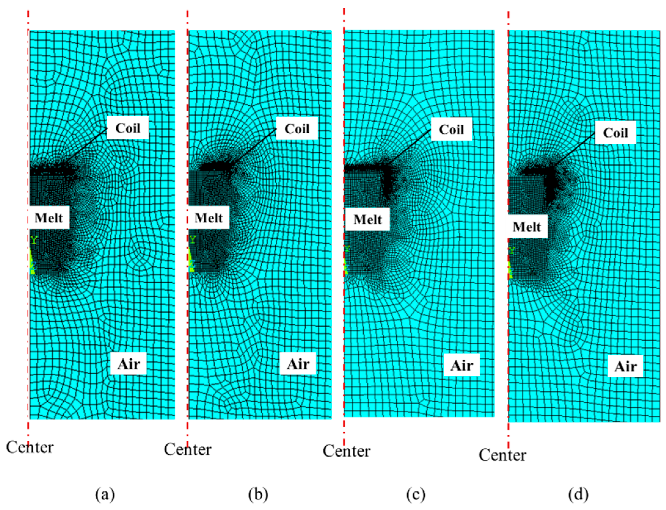
2.2. Numerical Simulation

The induced magnetic field and electric current were calculated according to Maxwell’s laws, which can be expressed as Equation (1):
{ × H = J + D t × E = B t B = 0 D = ρ
where H is magnetic field intensity, J is total current density vector, D is electric flux density, t is time, E is electric field intensity vector, B is magnetic flux density vector, ρ is electric charge density.
The casting setup consisted of a coil, air and the melt in the simulation. Two-D axisymmetric Finite Element Method (FEM) model was built on this setup by the ANSYS© 16.0 software. PLANE13 was chosen for analyzing, which is a controlled combinatorically by the Maxwell equation, Lorentz’s law and Joule’s law. Different grid sizes were chosen for different portion of the model. The finest grid was used in melt and coil (Figure 2). Because of different coil configuration, there was a little difference among the four models’ grids. This selection of the grid affected the automatically generated nodes in our simulation. We believe this difference has marginal impact on the simulated results.
The current profile in the coil was similar to what we used before [27] (Figure A1 in Appendix A). The relationship between the current and time was described as:
I ( t ) = I 0 exp ( ζ t ) sin ( ω t )
where I0 is a peak value in current, and ζ and ω are constant for the circuit.
The main parameters of the pulse current used in the simulation include peak value and pulse width of electric pulse. The electrical resistivity was assumed to be 2.42 × 10⁻⁷ and 1.72 × 10⁻⁸ Ω.m for the aluminum melt and the coil, respectively. The relative permeability was assumed to be 1 for the aluminum.

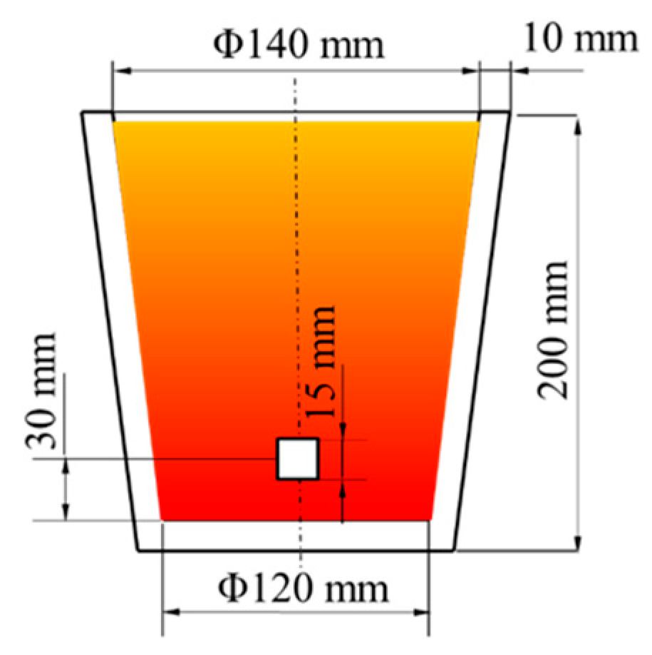
2.3. Experimental Part

The experimental setup is composed of a modulated PMO generator, water-cooled oscillation coils (produced by Shanghai University, Shanghai, China, see Figure 1), and molds made of graphite. The cavity size of molds was designed as Φ 140 mm × 200 mm, and the wall thickness of the mold is 10 mm. Prior to pouring, molds were preheated to 200 °C. About 7 kg commercial purity aluminum with the liquidus temperature of 660 °C was melted in a resistance furnace (produced by KERE FURNACE, Luoyang, China) and poured into molds at the pouring temperature of 750 ± 10 °C after being held for 30 min. The melts were treated immediately with PMO after pouring until the ingots solidified completely. The peak value and frequency of pulsed current were 450hI A and 444kt Hz, where hI and kt were the coefficients of the pulse generator and remained constant in the experiment. The solidified Al ingots were longitudinally sectioned along the center. The sections were etched in a mixture of 3 hydrochloric acid: 3 nitric acid: 5 water. Metallographic specimens were taken from these sections in the lower part of ingots (Figure 3). Specimens were mechanically polished by vibration polisher (VibroMet2, Buehler, IL, American) for 3 h and then electronically polished with a mixture of distilled water and fluorotic acid at 0.3–0.5 A/cm2 for 20–40 s. The microstructure of etched samples was examined in a Zeiss optical microscope (Axio Imager A2m, ZEISS, Oberkochen, Germany). The procedure for this experiment was the same as reported before [27].

3. Results

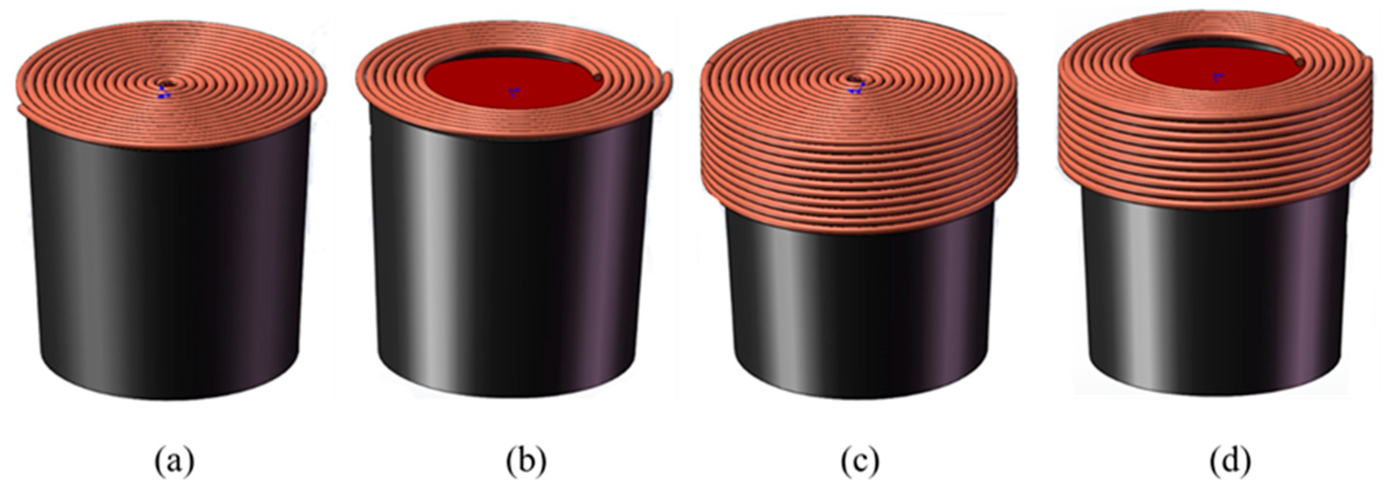
3.1. Simplification of Coil Configuration to Optimize PMO

In both small- and large-scale production of ingots, PMO coils have to be placed on top of the mold immediately after pouring. Consequently, slag control and surface examination are more difficult with PMO than that without. Our Previous simulation results showed that magnetic field induced by SPMO tended to cluster near the melt surface and along the mold wall, not at the center of the melt [24,27]. We deduced that if the coil could be given the form of a ring rather than a disc, slag control and surface examination would be much easier. The coils can also be placed on top of the mold before pouring. In order to compare discs with rings, we performed simulations in this study on SPMO, CPMO, simplified SPMO-H and CPMO-H using both forms.
In SPMO configuration, we found that using ring (SPMO-H) rather than disc (SPMO) would slightly reduce the intensity of electromagnetic field. In CPMO configuration, using ring (CPMO-H) rather than disc (CPMO) would have little effect on the distribution of an electromagnetic field in CPMO (Figure 4).
The macrographs of SPMO, SPMO-H, CPMO and CPMO-H treated ingots under the same current parameters showed that refinement was achieved in both SPMO (see Figure 5b,g) and SPMO-H treated ingots (see Figure 5c,h) under the same current peak value and frequency. SPMO and SPMO-H increased the equiaxial zone from 2.5 vol% (untreated (Figure 5a,f) [27] to 38.9% and 29.5%, respectively. The equiaxial grains were the coarsest in untreated ingot, whereas the average grain size decreased from 1063 µm [27] to 409 µm and 435 µm for samples treated by SPMO and SPMO-H, respectively (Table 1). The ratio of equiaxed zone and size of grains in the CPMO-H treated ingot (Figure 5e,j) were only marginally different from the CPMO treated ingot (Figure 5d,i). In other words, CPMO-H is almost as effective as CPMO.
The difference in coil configuration led to difference in inductance, which can be deduced by measurement of pulse width. We calculated the induction skin depth using the pulse width read from oscilloscope. Because the skin depth values for CPMO and CPMO-H were identical, CPMO and CPMO-H treated melts were almost the same. Because the skin depth values for CPMO and CPMO-H treated melts were about 16.7% greater than that with SPMO and the larger skin depth makes more nucleus fall from the wall and increased the nucleation rate, CPMO and CPMO-H treated ingots were significantly better than samples treated by SPMO and SPMO-H. Modification of SPMO to SPMO-H decreased the skin depth by 8.3% and led to reduced equiaxed zone volume fraction. In order to achieve the similar effect of SPMO by SPMO-H, more electrical current should be considered. The results showed that the coil could be modified for convenience in production.

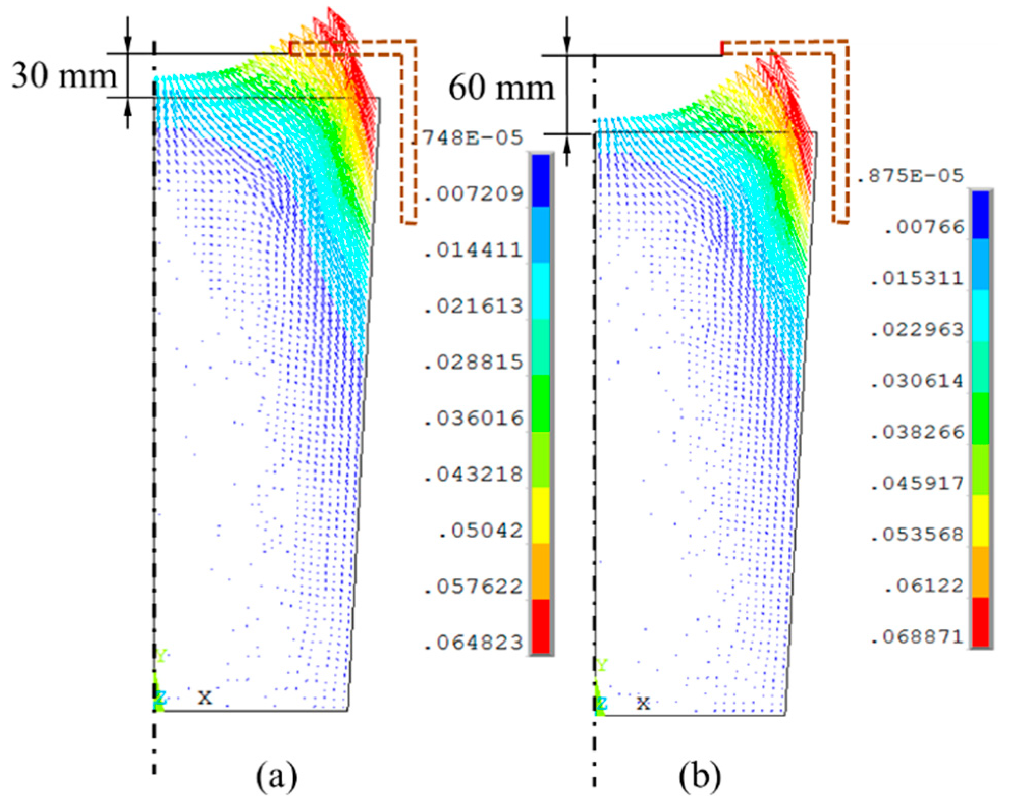
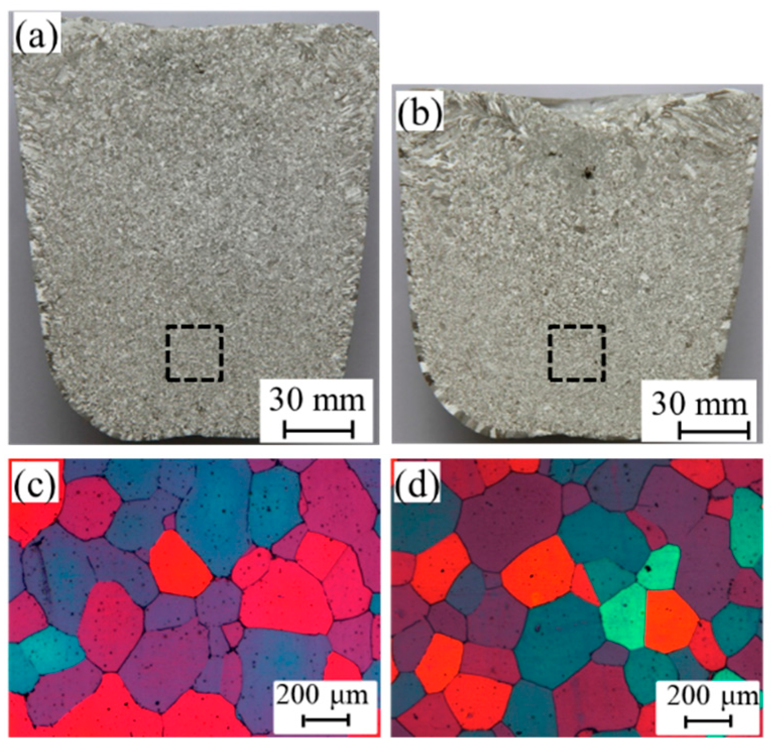
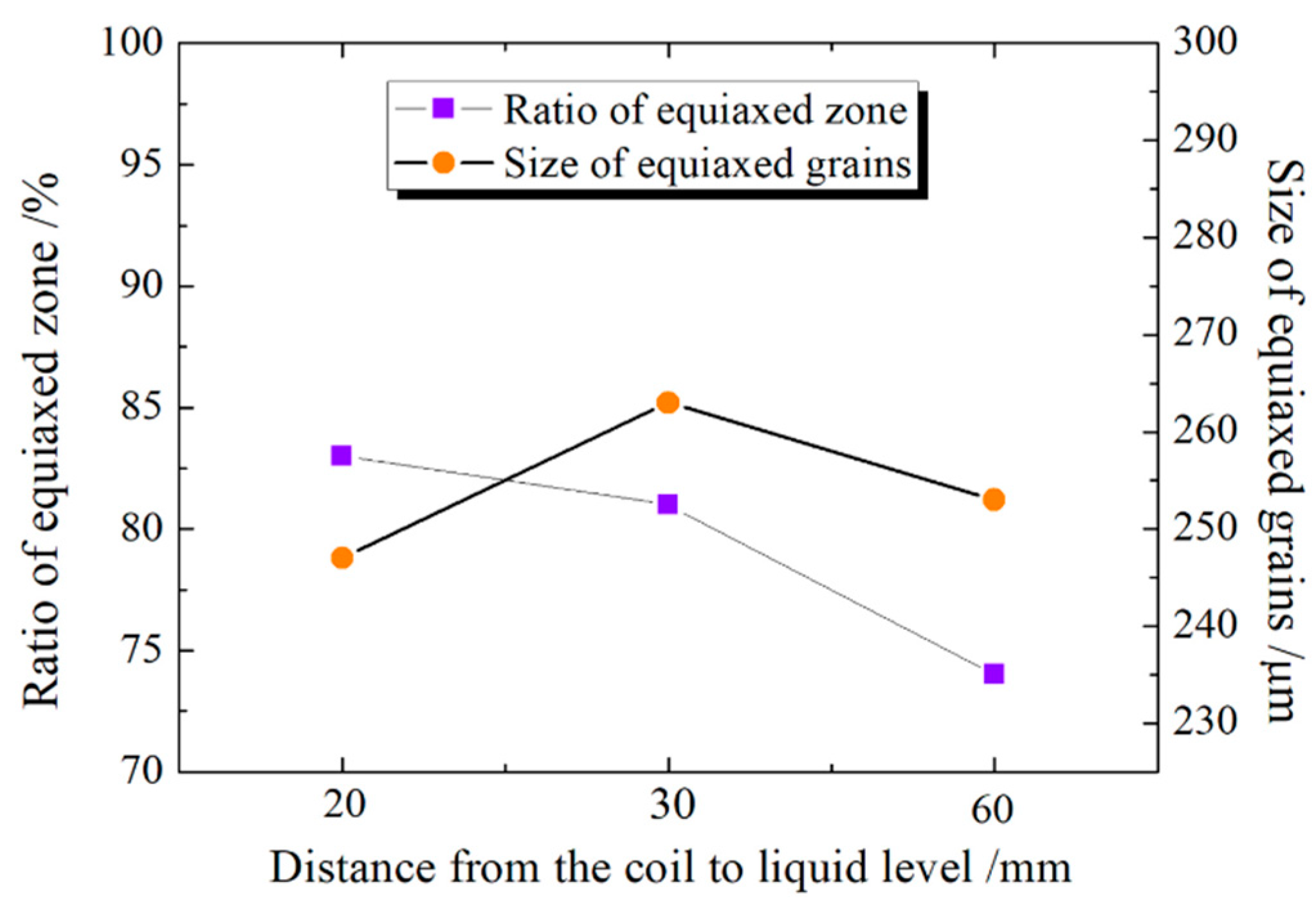
3.2. Effect of Liquid Level on the Refinement Effect of Al Ingot with CPMO-H Treated

Because melt surface level is dropping during solidification and the induced electromagnetic distribute mainly near the coil, it is important to understand if the dropping of surface reduces the refinement effect. We conducted an experiment using CPMO-H coil to study the effect of the distance between the coil and the melt surface on refinement under PMO using the same peak current and frequency (450hI A and 444kt Hz) as above. To compare the situation with distance between the coil and melt surface of 10 mm (Figure 4d), we studied the casting using distance of 30 mm (Figure 6a) and 60 mm (Figure 6b). Our calculation results showed that the distance had little influence on the distribution of magnetic flux intensity in melt (Figure 7). Our experimental results showed that an increase in the distance resulted in decrease of the ratio of equiaxed zone from 83% (10 mm in Figure 5d), to 81% (30 mm in Figure 8a) and to 74% (60 mm in Figure 8b). The grain sizes are 247 µm, 263 µm, 253 µm for samples treated with distance of 10, 30 and 60 mm, respectively. There is no obvious difference in average grain size within equiaxed zone for three cases (Figure 9). It could be concluded that the magnetic flux intensity was the major factor to solidification refinement. The similar distribution of magnetic intensity would produce similar refinement. In other words, if only ingot within equiaxed zone is used, the distance between the coil and melt level has nearly no effect on refinement by CPMO-H. In production, this is equivalent to section the top of ingots, which usually have shrinkage cavity on the top.

4. Conclusions

(1)
Ring coils allow operator to examine the melt and undertake operation without interfering pouring.
(2)
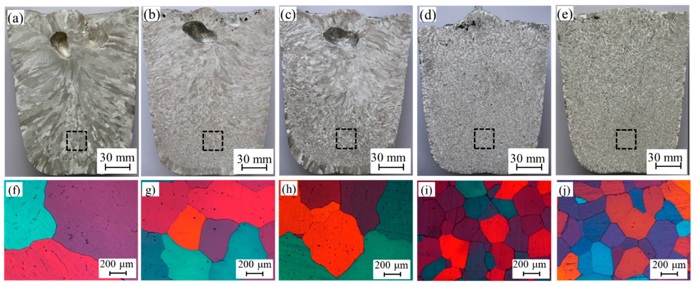
Ring coil SPMO-H reduced the equiaxed grain size but decreased the ratio of equiaxed zone. Ring coil CPMO-H reduced the equiaxed grain size without significantly changing the ratio of equiaxed zone.
(3)
The distance between the coil and melt has little effect on the grain sizes refined by CPMO-H. Refinement effect would not be reduced with dropping of melt level. CPMO-H could be applied in large scale ingots production.

Author Contributions

Conceptualization, Q.-j.Z.; data curation, J.Z. and J.-h.Y.; formal analysis, J.Z., J.-h.Y., K.H. and H.-g.Z.; funding acquisition, J.Z. and Q.-j.Z.; investigation, J.Z. and J.-h.Y.; material, R.-x.L.; methodology, J.Z., J.-h.Y., H.-g.Z., R.-x.L. and Q.-j.Z.; project administration, J.Z. and Q.-j.Z.; resources, R.-x.L.; software, J.Z. and J.-h.Y.; supervision, J.Z. and Q.-j.Z.; validation, J.Z., K.H. and H.-g.Z.; writing—original draft, J.Z.; writing—review and editing, K.H. and Q.-j.Z. All authors have read and agree to the published version of the manuscript.

Funding

This research was funded by the Natural Science Foundation of China, grant number 51704210, Natural Science Foundation of Hebei Province, grant number E2017105016 and National Key Research Program of China, grant number 2017YFB0701800. Part of work was undertaken in the National High Magnetic Field Laboratory, which is supported by US NSF DMR-1157490 and the State of Florida.

Acknowledgments

We thank Mary Tyler for editing the manuscript.

Conflicts of Interest

The authors declare no conflict of interest.

Appendix A

Figure A1. Variation of pulsed electricity in a coil.
Metals 10 00153 g0a1

References

  1. Zhao, W.L.; Ma, Q.X. Technological development of the forged low-pressure rotor of nuclear turbine in China. Appl. Mech. Mater. 2015, 703, 430–435. [Google Scholar] [CrossRef]
  2. Deng, L.P.; Wang, B.S.; Xiang, H.L.; Yang, X.F.; Niu, R.M.; Han, K. Effect of Annealing on the Microstructure and Properties of In-situ Cu–Nb Microcomposite Wires. Acta Metall. 2016, 29, 668–673. [Google Scholar] [CrossRef] [Green Version]
  3. Embury, J.; Han, K. A Survey of Processing Methods for High Strength-High Conductivity Wires for High Field Magnet Applications. In Megagauss Magnetic Field Generation, Its Application to Science and Ultra-High Pulsed-Power Technology, Proceedings of the VIIIth International Conference on Megagauss Magnetic Field Generation and Related Topics, Tallahassee, FL, USA, 18–23 October 1998; World Scientific: Singapore, 2004; pp. 147–153. [Google Scholar]
  4. Han, K. Strength and Ductility of Nanostructured Composites with Co-Deformable Components. Mater. Sci. Forum 2009, 864, 383–392. [Google Scholar] [CrossRef]
  5. Han, K. The fabrication, properties and microstructure of Cu–Ag and Cu–Nb composite conductors. Mater. Sci. Eng. A 1999, 267, 99–114. [Google Scholar] [CrossRef]
  6. Cheng, S.; Spencer, J.A.; Milligan, W.W. Strength and tension/compression asymmetry in nanostructured and ultrafine-grain metals. Acta Mater. 2003, 51, 4505–4518. [Google Scholar] [CrossRef]
  7. Han, K.; Zhou, X. Effect of high magnetic field on the processing of pearlitic steels. Mater. Manuf. Process. 2017, 32, 1317–1324. [Google Scholar] [CrossRef]
  8. Li, G.M.; Liu, Y.; Su, Y.; Wang, E.G.; Han, K. Influence of High Magnetic Field on As-Cast Structure of Cu-25wt%Ag Alloys. China Foundry 2013, 10, 162–166. [Google Scholar]
  9. Ecker, S.; Willers, B.; Nikrityuk, P.A.; Eckert, K.; Michel, U.; Zouhar, G. Application of a rotating magnetic field during directional solidification of Pb–Sn alloys: Consequences on the CET. Mater. Sci. Eng. A 2005, 413, 211–216. [Google Scholar] [CrossRef]
  10. Liao, X.L.; Zhai, Q.J.; Luo, J.; Chen, W.J.; Gong, Y.Y. Refining mechanism of the electric current pulse on the solidification structure of pure aluminum. Acta Mater. 2007, 55, 3103–3109. [Google Scholar] [CrossRef]
  11. Wang, G.; Nagasivamuni, B.; Ma, Q. The role of ultrasonic treatment in refining the as-cast grain structure during the solidification of an Al-2Cu alloy. J. Cryst. Growth 2014, 408, 119–124. [Google Scholar] [CrossRef] [Green Version]
  12. Li, H.T.; Wang, Y.; Fan, Z. Mechanism of enhanced heterogeneous nucleation during solidification in binary Al-Mg alloys. Acta Mater. 2012, 60, 1528–1537. [Google Scholar] [CrossRef] [Green Version]
  13. Metan, V.; Eigenfeld, K.; Räbiger, D. Grain size control in Al-Si alloys by grain refinement and electromagnetic Stirring. J. Alloys Compd. 2009, 487, 147–152. [Google Scholar] [CrossRef]
  14. Zhai, Q.J.; Gong, Y.Y.; Gao, Y.L.; Li, R.X.; Jing, J.X. Method and Apparatus for Fining Metal Solidified Organs by Using Magneto-Oscillation. China Patent No. CN200510030736.4, 27 October 2005. [Google Scholar]
  15. Liang, D.; Liang, Z.Y.; Sun, J.; Zhai, Q.J.; Wang, G.; David, H. Grain refinement of commercial pure Al treated by Pulsed Magneto-Oscillation on the top surface of melt. China Foundry 2015, 12, 48–53. [Google Scholar]
  16. Gong, Y.Y.; Luo, J.; Jing, J.X.; Xia, Z.Q.; Zhai, Q.J. Structure refinement of pure aluminum by pulse magneto-oscillation. Mater. Sci. Eng. A 2008, 497, 147–152. [Google Scholar] [CrossRef]
  17. Yin, Z.X.; Gong, Y.Y.; Li, B.; Cheng, Y.F.; Liang, D.; Zhai, Q.J. Refining of pure aluminum cast structure by surface magneto-oscillation. J. Mater. Process. Technol. 2012, 212, 2629–2634. [Google Scholar] [CrossRef]
  18. Li, H.C.; Liu, Z.; Li, R.X.; Gong, Y.Y.; Xu, Z.S.; Zhai, Q.J. Distribution of nonmetallic inclusions in molten steel under hot-top pulsed magneto-oscillation treatment. J. Iron Steel Res. Int. 2018, 25, 867–876. [Google Scholar] [CrossRef]
  19. Cheng, S.M.; Zhong, Y.Y.; Xu, Z.S.; Pei, N.; Zhai, Q.J.; Gong, Y.Y. Effect of flow on solidification structure of pure aluminum under pulsed magneto-oscillation. Mater. Sci. Technol. 2018, 34, 1212–1217. [Google Scholar] [CrossRef]
  20. Li, H.C.; Liu, Y.X.; Zhang, Y.H.; Liu, Z.; Zhai, Q.J. Effects of hot top pulsed magneto-oscillation on solidification structure of steel ingot. China Foundry 2018, 15, 110–116. [Google Scholar] [CrossRef] [Green Version]
  21. Gong, Y.Y.; Cheng, S.M.; Zhong, Y.Y.; Wang, X.; Zhang, Y.H.; Zhai, Q.J.; Zhong, H.G.; Xu, Z.S.; Yue, R.; Pei, N. Influence of electromagnetic parameters on solidification structure of pure Al in the case of identical power. J. Iron Steel Res. Int. 2018, 25, 854–861. [Google Scholar] [CrossRef]
  22. Zhao, J.; Cheng, Y.F.; Han, K.; Zhang, X.Z.; Xu, Z.S.; Zhai, Q.J. Numerical and Experimental studies of surface-pulsed magneto-oscillation on solidification. J. Mater. Process. Technol. 2016, 229, 286–293. [Google Scholar] [CrossRef] [Green Version]
  23. Liu, T.Y.; Sun, J.; Sheng, C.; Wang, Q.X.; Zhang, Y.H.; Li, L.J.; Zhong, H.G.; Zhai, Q.J. Influence of pulse magneto-oscillation on the efficiency of grain refiner. Adv. Manuf. 2017, 5, 143–148. [Google Scholar] [CrossRef]
  24. Edry, I.; Mordechai, T.; Frage, N. Effects of Treatment Duration and Cooling Rate on Pure Aluminum Solidification Upon Pulse Magneto-Oscillation Treatment. Metall. Mater. Trans. A 2016, 47, 1–7. [Google Scholar] [CrossRef]
  25. Edry, I.; Erukhimovitch, V.; Shoihet, A. Effect of impurity levels on the structure of solidified aluminum under pulse magneto-oscillation (PMO). J. Mater. Sci. 2013, 48, 8438–8442. [Google Scholar] [CrossRef]
  26. Edry, I.; Frage, N.; Hayun, S. The effect of pulse magneto-oscillation treatment on the structure of aluminum solidified under controlled convection. Mater. Lett. 2016, 182, 118–120. [Google Scholar] [CrossRef]
  27. Zhao, J.; Yu, J.H.; Han, K.; Zhong, H.G.; Li, R.X.; Zhai, Q.J. Improving the Solidified Structure by Optimization of Coil Configuration in Pulsed Magneto-Oscillation. Acta Metall. Sin. 2018, 31, 1334–1344. [Google Scholar] [CrossRef] [Green Version]
Figure 1. Coil configuration of PMO: (a) SPMO (plate coil was put on the top of mold) [27]; (b) SPMO-H (ring coil was put on the top of mold); (c) CPMO (plate coil was put on and around hot-top) [27]; (d) CPMO-H (ring coil was put on and around hot-top).
Metals 10 00153 g001
Figure 2. FEM models used in the simulation: (a) SPMO; (b) SPMO-H; (c) CPMO; (d) CPMO-H.
Metals 10 00153 g002
Figure 3. Geometry of the ingot and sampling location.
Metals 10 00153 g003
Figure 4. Distribution of magnetic flux intensity in melts at a quarter of one oscillation period of PMO (or T/4, see appendix. In our simulation, one oscillation period of PMO was divided into stages T/4, T/2, 3T/4 and 1T, where T is an oscillation period of PMO).
Metals 10 00153 g004
Figure 5. Effect of coil configuration on the solidified structure. (a), (f) untreated [27]; (b), (g) with SPMO; (c) (h) with SPMO-H; (d), (i) with CPMO; (e), (j) with CPMO-H.
Metals 10 00153 g005
Figure 6. Distribution of magnetic flux intensity with different liquid level at T/4. (a) 30 mm to the coil; (b) 60 mm to the coil.
Metals 10 00153 g006
Figure 7. Comparison of magnetic intensity vs time at the same position in melt at identical locations: Position A is in the center; position B is at the half radius; position C is at the edge in melt. All are located about 100 mm to the surface.
Metals 10 00153 g007
Figure 8. Effect of liquid level on the solidified structure of CPMO-H treated ingots: (a,c), 30 mm to the coil; (b,d) 60 mm to the coil.
Metals 10 00153 g008
Figure 9. Comparison of ratio of equiaxed zone and size of equiaxed grains with different distance from the coil to liquid level in CPMO-H treated ingots.
Metals 10 00153 g009
Table 1. Effect of coil configuration on PMO treatment.
Coil Configuration in PMOSPMOSPMO-HCPMOCPMO-H
Size of equiaxed grains (µm)435409269247
Ratio of equiaxed zone (%)38.929.593.292
Calculated skin depth (mm)12111414

