Abstract
In this study, Al-Zn-Mg-Cu alloy was refill friction spot welded, and the precipitates, dislocation, recovery, and recrystallization characteristics were focused. In the stir zone (SZ), continues dynamic recrystallization occurs under the intense plastic deformation. All the original GP (II) zones and η’ precipitates dissolved into the aluminum matrix under the welding heat input, and the stable η and E precipitates remained. In the thermo-mechanically affected zone (TMAZ), high-density dislocations and subgrains boundaries can be observed. The continued dynamic recrystallization was not activated and only dynamic recovery occurs. Sub-boundaries and high-density dislocations in this zone can be observed. In this zone, the η precipitates are coarsened and dissolution is the main evolution mechanism for the GP (II) zones and η’ precipitates. In the heat-affected zone (HAZ), no dislocation was induced and all the initial precipitates were coarsened under the welding heat input. The HAZ, the TMAZ, and the SZ constitute a soft region in the refill friction stir spot welding (RFSSW) joint, and the minimum value located at the interface between the HAZ and the TMAZ.
1. Introduction
For the Al-Zn-Mg-Cu alloys, the introduction of Zn and Mg makes the formation of MgZn2 strengthening particles in the alloys. As a result, the Al-Zn-Mg-Cu alloys has higher mechanical properties than other aluminum alloys such as Al-Si, Al-Mg, and Al-Mg-Si alloys. In recent decades, the Al-Zn-Mg-Cu alloys have been widely applied in aircraft manufacturing. They are also expected to be applied in the automobile manufacturing owing to their high specific strength. However, the resistance spot welding (RSW) which is the conventional joining technology for the car body has obvious disadvantages in joining aluminum alloys, such as high energy consumption, low mechanical property, and high welding deformation [1]. In order to realize high quality joining for aluminum alloys, a new solid-state welding technology called refill friction stir spot welding (RFSSW) is developed by Helmholtz-Zentrum Geesthacht [2]. Because the welded material is not melted in the RFSSW process, the crack and pore which are common welding defects in resistance spot welding can be avoided. The RFSSW has been approved to be a promising technology by recent studies [3,4].
The schematic for RFSSW process is shown in Figure 1. The welding tool for RFSSW consists of a pin, a sleeve, and a clamping ring (see Figure 1a). In the welding process the sleeve and pin rotate continuously and the workpiece is fixed to the back anvil by the clamping ring. At the beginning of RFSSW, the sleeve plunges downward and the pin retreats upwards simultaneously. Accordingly, the plastic material is extruded into the cavity of the sleeve (see Figure 1b). After that, the sleeve retreats upwards and the pin plunges downwards to extrude the plastic material from the cavity into the weld spot (see Figure 1c). At the end of RFSSW, a weld spot without a keyhole can be obtained and the welding tool moves away from the workpiece (see Figure 1d). The weld spot can be completely refilled, so the carrying area capability of the RFSSW is increased [5].

Figure 1.
Schematic of refill friction stir spot welding (RFSSW): (a) clamping stage, (b) plunging stage, (c) retreating stage, and (d) finishing stage.
Up to now, most of the studies on the RFSSW of Al-Zn-Mg-Cu alloys (7xxx series aluminum alloys) were focus on the relationships among welding parameters, weld deformation, and mechanical properties of the joints [6]. For instance, Kluz et al. [7] built an adequate mathematical model between the maximum load capacity of the joint and the welding parameters for RFSSW of 7075-T6 aluminum alloy on the basis of Weierstrass’ theorem. They found that tool rotational speed had the greatest impact on the load capacity of the joints. Kubit et al. [8] conducted the RFSSW experiments on the 0.8 mm thick 7075-T6 aluminum alloy. The results indicated that a visible structural notch caused by too rapid penetration of the sleeve considerably degraded the load capacity of the joint. Shen et al. [9] stated that the nugget thickness of the RFSSW joint of 7075-T6 aluminum alloy increased with increasing welding time and plunge depth, and the welding time played a decisive role in nugget size.
The microstructures also have significant effects on the mechanical properties of the RFSSW joints of Al-Zn-Mg-Cu alloys. Only a few relative studies have been conducted. Zhao et al. [10] studied the microstructures of RFSSW joints of 7B04-T74 aluminum alloy at different tool rotation speeds. They found that the grains in the outer stir zone were equiaxed, and the grains in the inner stir zone were elongated and coarsened. They also pointed out that continuous eutectic films can be observed in the stir zone (SZ) when the tool rotation speed was relatively high, and local liquation crack can be formed when the eutectic films were gathered. This liquation crack had significant adverse effect on the tensile shear load of the RFSSW joint [5]. In addition, it has been well-demonstrated that the precipitates of η’ (MgZn2) formed by the alloying elements (Zn, Mg), and the dislocations introduced by the plastic deformation also had significant effects on the strength of the Al-Zn-Mg-Cu alloys [11]. It can be concluded that the precipitates and dislocations should also play a key role in the mechanical properties of the RFSSW joint. However few relative studies have been carried out.
In order to further reveal the microstructural characteristics of the RFSSW joint of the Al-Zn-Mg-Cu alloys, 7B04-T74 aluminum alloy were refill friction stir spot welded in this study. The precipitates, dislocation, recovery, and recrystallization characteristics which were rarely concerned before were studied using transmission electron microscopy.
2. Material and Experiment
7B04-T74 aluminum alloy sheets, which is a kind of Al-Zn-Mg-Cu alloy with 2 mm thickness, were used as the base material, whose chemical compositions are listed in Table 1. Standard T74 heat treatment process was conducted on the base material before welding. The heat treatment process can be divided into three steps: solution heat treatment (470 °C) → low temperature artificial aging (120 °C) → high temperature artificial aging (170 °C). For the Al-Zn-Mg-Cu alloy, the precipitation sequence can be summarized as: solid solution → Guinier–Preston (GP) zones → metastable η’ (MgZn2) → stable η (MgZn2) [12]. The phases that play the major strengthening effect are η’ and GP zones [11]. The GP zones serve as nuclei for η’, and they can be categorized as solute-rich clusters GP (I) and vacancy-rich solute clusters GP(II) zones [13,14].

Table 1.
Chemical compositions of 7B04-T74 aluminum alloy.
The welding specimens, comprising two 80 mm × 30 mm sheets with an overlap area of 30 mm × 50 mm, were welded at the center of the overlap area. The configuration of the joint is shown in Figure 2a. The welding tool consisted of a 14.5 mm diameter clamping ring, an 8.9 mm diameter threaded sleeve, and a 5.2 mm diameter pin. The employed tool rotation speed, sleeve motion speed, and sleeve plunge depth were 1500 rpm, 1 mm/s, and 3 mm respectively. This set of parameters had been proved to be optimized by the present authors [10]. Previous study conducted by the present authors indicated that a part of plastic material would overflow out from the welding region in the RFSSW process, the left material was not enough to refill the welding spot. A surface indentation with 0.15 mm depth was an effective method to compress the left material and offset the material loss [15]. As a result, a surface indentation with 0.15 mm depth was applied in this study. Accordingly, the total welding time was 5.85 s.
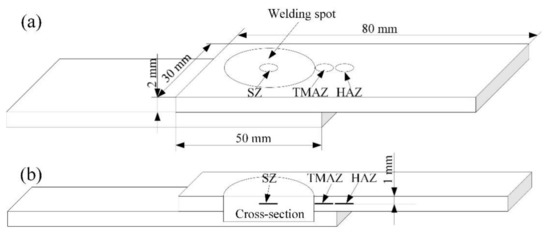
Figure 2.
Schematic of specimen configuration and TEM specimens locations: (a) joint configuration and (b) joint cross-section.
After welding, metallographic sample was cut using an electrical-discharge cutting machine, and then it was sanded and polished. The final surfaces of the metallographic samples should be guaranteed through the center line of spot welded joint. After that, the metallographic samples were etched with Keller’s reagent, and metallographic analyses were carried out by optical microscopy (OM, Olympus-MPG3, Olympus, Tokyo, Japan). Transmission electron microscopy (TEM PHILIPS CM12, Philips, Amsterdam, The Netherlands) was used to detect the precipitates and substructures characteristics. The foil disk specimens for TEM were cut from the different zones of the RFSSW joint. The locations of the TEM specimens are shown in Figure 2a,b. The electron transparent thin sections were prepared through double jet electro-polishing using a solution of 30% nitric acid in methanol (18 V and −35 °C).
3. Results and Discussions
3.1. Microstructural Characteristics
In order to study the microstructural characteristics in different zones of the RFSSW joint in detail, the RFSSW joint was divided into four microstructure zones, i.e., base material zone (BMZ), stir zone (SZ), thermo-mechanically affected zone (TMAZ), and heat-affected zone (HAZ), according to the previous studies on FSSW [16,17,18,19]. The different zones are marked in Figure 3.

Figure 3.
Cross-section of the RFSSW joint.
3.1.1. Base Material Zone
The microstructural characteristics of the BMZ are shown in Figure 4. No dislocations can be detected in this zone though the base material experienced rolling process. As shown in Figure 4a, rod like precipitates with average 130 nm length can be observed along the grain boundaries, and these precipitates are incoherent with the matrix. Referencing to the previous studies [11,13,20], these precipitates should be stable η precipitates. In addition, precipitate free zone (PFZ) with the width of approximately 30 nm can be also observed near the grain boundaries. Three kinds of precipitates can be observed within the grains as shown in Figure 4b. They are spherical like precipitates with average diameter of 10 nm, plate like precipitates with average length of 30 nm, and rod like precipitates whose average length are 120 nm. In order to identify the precipitates, selected area diffraction patterns (SAED) along [001]Al and [111]Al were performed, as shown in Figure 4c,d. Referring to the previous TEM works conducted by Su et al. [11] and Stiller et al. [21], it can be concluded that GP (II) zones, η’ and η precipitates exist in the grains, but no GP (I) zones exist. Feng et al. [22] pointed out that the GP (II) zones, η’ and η are spherical, plate, and rod like respectively. According to their results, the different precipitates in the BMZ can be distinguished, as shown in see in Figure 4b.
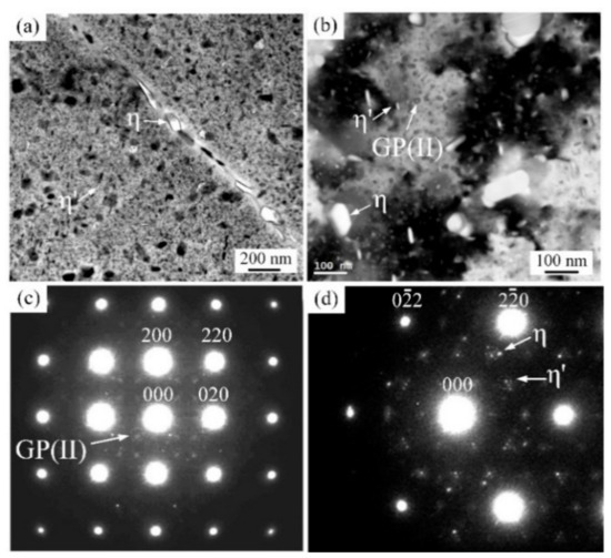
Figure 4.
Precipitates characteristics in base material zone (BMZ): (a) precipitates and precipitate free zone (PFZ), (b) magnification of grain inner, (c) diffraction pattern along [001]Al, and (d) diffraction pattern along [111]Al.
3.1.2. Stir Zone
The SZ is stirred directly in the RFSSW process, so this zone experiences the most intense welding heat input and plastic deformation. As shown in Figure 5, the dislocations and recover structures can be observed in the fine recrystallization grains by TEM. Su et al. [11] attributed these characteristics to the further plastic deformation after recrystallization. It should be noted that the different stages of continued dynamic recrystallization (CDRX) process can be observed in the SZ. In the stage shown in Figure 5a, the dislocations induced by the intense plastic deformation are dispersedly distributed in the grain. With the increasing plastic deformation, the dislocations tangles together and the dislocation cells are formed, as shown in Figure 5b. After that, the dislocations in the cell are absorbed by the cell wall. As a result, the dislocation density is higher in the cell wall than that in the cell inner. The dislocations can glide and climb at high welding temperature, this leads high temperature recovery i.e., grain polygonization to occur. In the grain polygonization process, the dislocations arrange more regularly. Therefore, dislocation walls with low energy reticular dislocation structure are formed, as shown in Figure 5c. In addition, it can be seen that the dislocations migrate into the dislocation wall in order to harmonize the increasing plastic deformation. With the further recovery, the dislocation density in the dislocation walls decreases and the subgrains boundaries are formed. This shows that the grains consisting of some subgrains are formed, as shown in Figure 5d. After that, in order to harmonize the plastic deformation of the adjacent subgrains, the subgrains boundaries sequentially absorb the dislocations. Meanwhile, the subgrains rotate, until the low-angle boundaries turn into the high-angle boundaries. It can be concluded that, CDRX should occur during RFSSW.
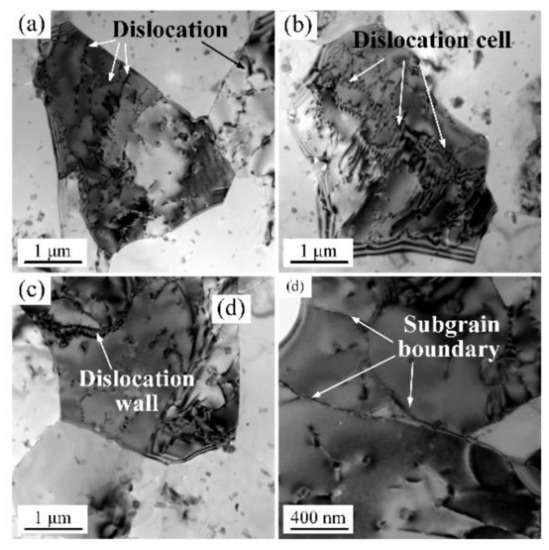
Figure 5.
Dislocations and recover structures in the stir zone (SZ): (a) dislocation multiplication, (b) dislocation cells, (c) dislocation wall, and (d) sub-boundaries.
The precipitates are shown in Figure 6. After welding, the stable η particles with typical rod shape can be observed in the SZ, as shown in Figure 6a. The results of SAED along [001]Al and [111]Al show that there are nearly no η’ precipitates or GP zones in the SZ (see Figure 6b,c). This indicates that nearly all the η’ precipitates or GP zones are dissolved into the matrix under the high welding heat input, and only the large η particles are remained. It is worth noting that the η particles obviously distribute along the dislocations and subgrains boundaries. This indicates that the remained η particles can hinder the migration of the dislocations and subgrains boundaries, and then inhibit the growth of the recrystallization grains. In addition, some spherical like particles can be also observed along the dislocation. In order to determine the spherical like particles, energy dispersive spectroscopy (EDS) analysis was conducted, as shown in Figure 6d. The result shows that Cr element is enriched in the spherical like particles. This is a typical characteristic of E phase (Mg3Cr2Al18) in the Al-Zn-Mg-Cu alloys [22]. It can be seen that the E phase particles can also pin dislocations and subgrains boundaries.
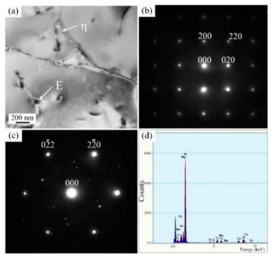
Figure 6.
Precipitates characteristics and EDS results in SZ: (a) precipitates characteristics, (b) diffraction pattern along [001]Al, (c) diffraction pattern along [111]Al and (d) EDS result of spherical precipitates.
3.1.3. Thermo-Mechanically Affected Zone
The TMAZ is not directly stirred by the welding tool, so the plastic deformation and corresponding strain are moderate. As shown in Figure 7a, dislocations with high density and some sub-boundaries can be observed in the TMAZ, but no equiaxed recrystallized grains can be detected. That is to say, in the TMAZ only dynamic recovery occurred, and the CDRX is not activated. For the dynamic recrystallization of aluminum alloys, the critical condition can be determined by Sellars model [23]:
where εc is the critical strain of dynamic recrystallization, εp is the peak strain, Q1 is thermal deformation activity energy, is strain rate, R is gas constant, T is absolute temperature, a1, a2 and m are constant. The welding temperature in the TMAZ is low, and this leads to relatively high critical strain for dynamic recrystallization. As a result, the moderate strain in the TMAZ is not sufficient to activate the CDRX process.
εc = a1εp
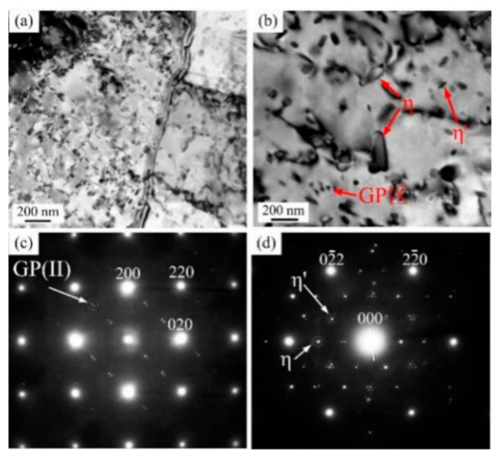
Figure 7.
Dislocations and precipitates characteristics in thermo-mechanically affected zone (TMAZ): (a) distributions, (b) precipitates (c) diffraction pattern along [001]Al, and (d) diffraction pattern along [111]Al.
After welding, spherical precipitates with average diameter of 30 nm, plate-like precipitates with average length of 95 nm, and rod-like precipitates with average length of 220 nm can be observed in the TMAZ (see Figure 7b). According to the results of SAED along [001]Al and [111]Al (see Figure 7c,d), they should be GP (II) zones, η’ and η phases respectively. Compared with the BMZ, the sizes of all the precipitates are larger and the precipitate density is smaller in the TMAZ. Fuller et al. [13] pointed out that the dissolution temperatures of the GP (II) zones, η’ and η precipitates were about 150 °C and 200 °C and higher than 300 °C respectively. The precipitation temperatures of the η precipitates was about 250 °C. According to the study conducted by Zhao et al. [24], the peak temperature in the TMAZ in the RFSSW process of 7B04-T74 aluminum was about 370 °C. It can be concluded that dissolution is the main evolution mechanism for the GP (II) zones and η’ precipitates, and coarsen is the main evolution mechanism for η precipitates.
3.1.4. Heat-Affected Zone
The HAZ only experiences welding thermal cycle without plastic deformation. Thus, no dislocation can be detected in this zone (see Figure 8a,b). According to the results of SAED as shown in Figure 8c,d, the precipitates in the TMAZ can be defined as the GP (II) zones, η’ and η phases. The average sizes of these precipitates are 18 nm, 45 nm and 160 nm respectively. In addition, 70 nm width PFZ can be also observed. All the sizes of the precipitates and PFZ in the HAZ are increased compared with the BMZ. This is a typical characteristic of overaging of aluminum alloy caused by the welding heat input.
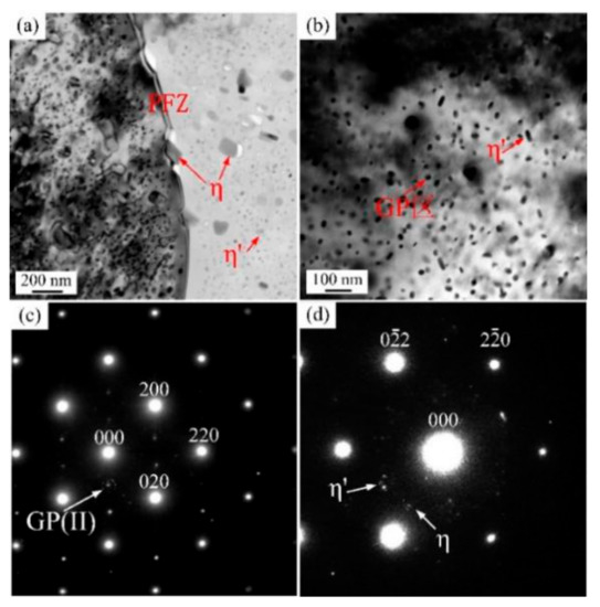
Figure 8.
Precipitates characteristics in heat-affected zone (HAZ): (a) PFZ and precipitates characteristics, (b) magnification of grain inner (c) diffraction pattern along [001]Al, (d) diffraction pattern along [111]Al.
3.2. Microhardness Distribution
For the Al-Zn-Mg-Cu alloys, the precipitation strengthening is the major strengthening mechanism. The small GP (II) zones and the η’ precipitates which are respectively coherent and semi-coherent with the aluminum matrix play the dominant strengthening effects. The large η phases that are non-coherent with the aluminum matrix have little effect on the strength of the aluminum alloys [22,25,26,27]. Besides the precipitation strengthening, the solution strengthening, fine grain strengthening, and dislocations strengthening mechanisms also make moderate contributions to the strength of the aluminum alloys [28,29,30]. Figure 9 shows the hardness distribution along the mid-thickness line of upper sheet on the cross-section of the RFSSW joint. Comparing with the BMZ whose hardness is about 175 Hv, the HAZ, the TMAZ, and the SZ constitute a soft region in the RFSSW joint. It can be seen that the soften region for RFSSW should be more narrow than that of the other fusion welding techniques [31,32]. In the HAZ, the precipitates are coarsened under the welding heat, so their strengthening effect is weakened. As a result, the hardness in this zone are lower than that in the BMZ. The hardness value consistently decreases from the BMZ to the minimum value at the HAZ/TMAZ interface, because the welding heat is higher near the weld center. In the TMAZ, although the main strengthening precipitates are coarsened and partially dissoluted, the dislocations introduced by the plastic deformation begin to contribute to the material strength. As a result, the hardness in the TMAZ constantly increases from the HAZ/TMAZ interface to the TMAZ/SZ interface. In the SZ, all the strengthening phases i.e., GP(II) zones and η’ precipitates are dissolved, therefore the precipitation strengthening effect in the SZ is poor. Nevertheless, the solid solubility and the dislocation density are relatively high, and the grains are fine in this zone, As a result, the hardness of the SZ is higher than that in the HAZ and TMAZ. In addition, because of the asymmetric heat emission condition of the lap configuration of the RFSSW joint, the distribution curve of the hardness presents asymmetric “W” shape.
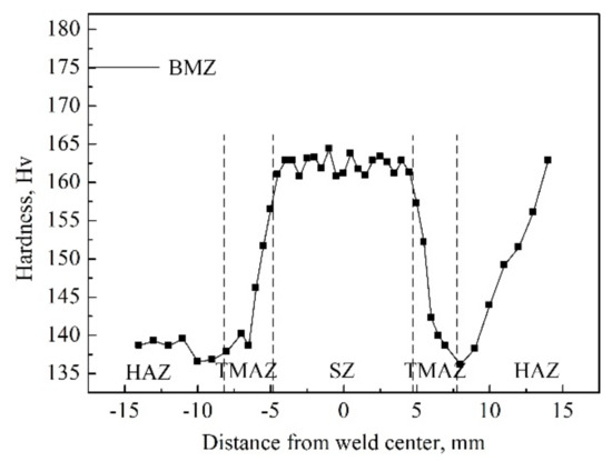
Figure 9.
Hardness distribution along the mid-thickness line of upper sheet on the cross-section of the RFSSW joint.
4. Conclusions
In this study, 7B04-T74 aluminum was friction spot welded. The precipitates, dislocation, recovery, and recrystallization characteristics were studied. The conclusions of significance are drawn as follows:
- In the SZ, CDRX occurs under the intense plastic deformation. All the original GP (II) zones and η’ precipitates dissolved into the aluminum matrix under the welding heat input, and the stable η and E precipitates are remained. The η and E precipitates can inhibit the dislocation migration and grains growth.
- In the TMAZ, high-density dislocations and subgrains boundaries can be observed. The CDRX was not activated and only dynamic recovery occurs. Sub-boundaries and high-density dislocations in this zone can be observed. In this zone, the η precipitates are coarsened and dissolution is the main evolution mechanism for the GP (II) zones and η’ precipitates.
- In the HAZ, no dislocation was induced and all the initial precipitates were coarsened under the welding heat input.
- The HAZ, the TMAZ, and the SZ constitute a soft region in the RFSSW joint. The distribution curve of the hardness values presented an asymmetric “W” shape, and the minimum value located at the interface between the HAZ and the TMAZ.”
Author Contributions
Formal analysis, Y.Z., C.W. and S.M.; investigation, Y.Z.; data curation, C.W., S.M. and J.T.; writing—original draft preparation, Y.Z.; writing—review and editing, Y.Z.; supervision, S.M.; project administration, Y.Z., C.D and Y.Y.; funding acquisition, Y.Z., C.D. and J.T. All authors have read and agreed to the published version of the manuscript.
Funding
The authors are grateful to be supported by the National Natural Science Foundation of China (51905112), by the Science and Technology Plan Project of Guangzhou City (201807010068), by the National Key Research and Development Program of China (2018YFB1306404), by the Key Areas Research and Development Program of Guangdong Province (2019B090921003), and by the GDAS’ Project of Science and Technology Development (2016GDASRC-0203 and 2020GDASYL-20200301001).
Conflicts of Interest
The authors declare no conflict of interest.
References
- Shen, Z.; Yang, X.; Zhang, Z.; Cui, L.; Yin, Y. Mechanical Properties and Failure Mechanisms of Friction Stir Spot Welds of Aa 6061-T4 Sheets. Mater. Des. 2013, 49, 181–191. [Google Scholar] [CrossRef]
- Zhou, L.; Luo, L.Y.; Zhang, T.P.; He, W.X.; Huang, Y.X.; Feng, J.C. Effect of Rotation Speed on Microstructure and Mechanical Properties of Refill Friction Stir Spot Welded 6061-T6 Aluminum Alloy. Int. J. Adv. Manuf. Technol. 2017, 92, 3425–3433. [Google Scholar] [CrossRef]
- Lacki, P.; Derlatka, A. Influence of Pu Foam Reinforcement of I-Beam on Buckling Resistance. Compos. Struct. 2018, 202, 201–209. [Google Scholar] [CrossRef]
- Lacki, P.; Derlatka, A.; Winowiecka, J. Analysis of the Composite I-Beam Reinforced with Pu Foam with the Addition of Chopped Glass Fiber. Compos. Struct. 2019, 218, 60–70. [Google Scholar] [CrossRef]
- Zhao, Y.; Wang, C.; Li, J.; Tan, J.; Dong, C. Local Melting Mechanism and Its Effects on Mechanical Properties of Friction Spot Welded Joint for Al-Zn-Mg-Cu Alloy. J. Mater. Sci. Technol. 2017, 34, 185–191. [Google Scholar] [CrossRef]
- Shen, Z.; Ding, Y.; Gerlich, A.P. Advances in Friction Stir Spot Welding. Crit. Rev. Solid State Mater. Sci. 2019, 1–78. [Google Scholar] [CrossRef]
- Kluz, R.; Kubit, A.; Trzepiecinski, T.; Faes, K. Polyoptimisation of the Refill Friction Stir Spot Welding Parameters Applied in Joining 7075-T6 Alclad Aluminium Alloy Sheets Used in Aircraft Components. Int. J. Adv. Manuf. Technol. 2019, 103, 3443–3457. [Google Scholar] [CrossRef]
- Kubit, A.; Kluz, R.; Trzepieciński, T.; Wydrzyński, D.; Bochnowski, W. Analysis of the Mechanical Properties and of Micrographs of Refill Friction Stir Spot Welded 7075-T6 Aluminium Sheets. Arch. Civ. Mech. Eng. 2018, 18, 235–244. [Google Scholar] [CrossRef]
- Shen, Z.; Chen, Y.; Hou, J.S.C.; Yang, X.; Gerlich, A.P. Influence of Processing Parameters on Microstructure and Mechanical Performance of Refill Friction Stir Spot Welded 7075-T6 Aluminium Alloy. Sci. Technol. Weld. Join. 2015, 20, 48–57. [Google Scholar] [CrossRef]
- Zhao, Y.Q.; Liu, H.J.; Lin, Z.; Chen, S.X.; Hou, J.C. Microstructures and Mechanical Properties of Friction Spot Welded Alclad 7b04-T74 Aluminium Alloy. Sci. Technol. Weld. Join. 2014, 19, 617–622. [Google Scholar] [CrossRef]
- Su, J.Q.; Nelson, T.W.; Mishra, R.; Mahoney, M. Microstructural Investigation of Friction Stir Welded 7050-T651 Aluminium. Acta Mater. 2003, 51, 713–729. [Google Scholar] [CrossRef]
- Sha, G.; Cerezo, A. Early-Stage Precipitation in Al–Zn–Mg–Cu Alloy (7050). Acta Mater. 2004, 52, 4503–4516. [Google Scholar] [CrossRef]
- Fuller, C.B.; Mahoney, M.W.; Calabrese, M.; Micona, L. Evolution of Microstructure and Mechanical Properties in Naturally Aged 7050 and 7075 Al Friction Stir Welds. Mater. Sci. Eng. A 2010, 527, 2233–2240. [Google Scholar] [CrossRef]
- Berg, L.K.; Gjønnes, J.; Hansen, V.; Li, X.Z.; Knutson-Wedel, M.; Waterloo, G.; Schryvers, D.; Wallenberg, L.R. Gp-Zones in Al–Zn–Mg Alloys and Their Role in Artificial Aging. Acta Mater. 2001, 49, 3443–3451. [Google Scholar] [CrossRef]
- Zhao, Y.Q.; Liu, H.J.; Chen, S.X.; Lin, Z.; Hou, J.C. Effects of Sleeve Plunge Depth on Microstructures and Mechanical Properties of Friction Spot Welded Alclad 7b04-T74 Aluminum Alloy. Mater. Des. 2014, 62, 40–46. [Google Scholar] [CrossRef]
- Reimann, M.; Goebel, J.; dos Santos, J.F. Microstructure Evolution and Mechanical Properties of Keyhole Repair Welds in Aa 2219-T851 Using Refill Friction Stir Spot Welding. J. Mater. Eng. Perform. 2018, 27, 5220–5226. [Google Scholar] [CrossRef]
- Sánchez Egea, A.J.; Rodríguez, A.; Celentano, D.; Calleja, A.; López de Lacalle, L.N. Joining Metrics Enhancement When Combining Fsw and Ball-Burnishing in a 2050 Aluminium Alloy. Surf. Coat. Technol. 2019, 367, 327–335. [Google Scholar] [CrossRef]
- Rodríguez, A.; Calleja, A.; López de Lacalle, L.N.; Pereira, O.; González, H.; Urbikain, G.; Laye, J. Burnishing of Fsw Aluminum Al–Cu–Li Components. Metals 2019, 9, 260. [Google Scholar] [CrossRef]
- Urbikain, G.; Perez, J.M.; Lacalle, L.N.L.; d Andueza, A. Combination of Friction Drilling and Form Tapping Processes on Dissimilar Materials for Making Nutless Joints. Proc. Inst. Mech. Eng. Part B: J. Eng. Manuf. 2016, 232, 1007–1020. [Google Scholar] [CrossRef]
- Gerlich, A.; Avramovic-Cingara, G.; North, T.H. Stir Zone Microstructure and Strain Rate During Al 7075-T6 Friction Stir Spot Welding. Metall. Mater. Trans. A 2006, 37, 2773–2786. [Google Scholar] [CrossRef]
- Stiller, K.; Warren, P.J.; Hansen, V.; Angenete, J.; Gjønnes, J. Investigation of Precipitation in an Al–Zn–Mg Alloy after Two-Step Ageing Treatment at 100° and 150 °C. Mater. Sci. Eng. A 1999, 270, 55–63. [Google Scholar] [CrossRef]
- Feng, A.H.; Chen, D.L.; Ma, Z.Y. Microstructure and Cyclic Deformation Behavior of a Friction-Stir-Welded 7075 Al Alloy. Metall. Mater. Trans. A 2010, 41, 957–971. [Google Scholar] [CrossRef]
- Liu, J.; Cui, Z.; Ruan, L. A New Kinetics Model of Dynamic Recrystallization for Magnesium Alloy Az31b. Mater. Sci. Eng. A 2011, 529, 300–310. [Google Scholar] [CrossRef]
- Zhao, Y.; Wang, C.; Dong, C.; Deng, J.; Tan, J. Numerical Study on a Thermal Process in Friction Spot Welding of Al-Zn-Mg-Cu Alloy. Weld. World 2018, 62, 931–939. [Google Scholar] [CrossRef]
- Fu, R.D.; Sun, Z.Q.; Sun, R.C.; Li, Y.; Liu, H.J.; Liu, L. Improvement of Weld Temperature Distribution and Mechanical Properties of 7050 Aluminum Alloy Butt Joints by Submerged Friction Stir Welding. Mater. Des. 2011, 32, 4825–4831. [Google Scholar]
- Rhodes, C.G.; Mahoney, M.W.; Bingel, W.H.; Spurling, R.A.; Bampton, C.C. Effects of Friction Stir Welding on Microstructure of 7075 Aluminum. Scr. Mater. 1997, 36, 69–75. [Google Scholar] [CrossRef]
- Jata, K.V.; Sankaran, K.K.; Ruschau, J.J. Friction-Stir Welding Effects on Microstructure and Fatigue of Aluminum Alloy 7050-T7451. Metall. Mater. Trans. A 2000, 31, 2181–2192. [Google Scholar] [CrossRef]
- Lotfi, A.H.; Nourouzi, S. Effect of Welding Parameters on Microstructure, Thermal, and Mechanical Properties of Friction-Stir Welded Joints of Aa7075-T6 Aluminum Alloy. Metall. Mater. Trans. A 2014, 45, 2792–2807. [Google Scholar] [CrossRef]
- İpekoğlu, G.; Çam, G. Effects of Initial Temper Condition and Postweld Heat Treatment on the Properties of Dissimilar Friction-Stir-Welded Joints between Aa7075 and Aa6061 Aluminum Alloys. Metall. Mater. Trans. A 2014, 45, 3074–3087. [Google Scholar] [CrossRef]
- McNelley, T.R.; Swaminathan, S.; Su, J.Q. Recrystallization Mechanisms during Friction Stir Welding/Processing of Aluminum Alloys. Scr. Mater. 2008, 58, 349–354. [Google Scholar] [CrossRef]
- Martínez, S.; Lamikiz, A.; Ukar, E.; Calleja, A.; Arrizubieta, J.A.; Lopez de Lacalle, L.N. Analysis of the Regimes in the Scanner-Based Laser Hardening Process. Opt. Lasers Eng. 2017, 90, 72–80. [Google Scholar] [CrossRef]
- Sanchez, J.A.; Plaza, S.; Lopez De Lacalle, L.N.; Lamikiz, A. Computer Simulation of Wire-Edm Taper-Cutting. Int. J. Comput. Integr. Manuf. 2006, 19, 727–735. [Google Scholar] [CrossRef]
© 2020 by the authors. Licensee MDPI, Basel, Switzerland. This article is an open access article distributed under the terms and conditions of the Creative Commons Attribution (CC BY) license (http://creativecommons.org/licenses/by/4.0/).