Review

A Critical Review of Approaches to the Design of Floating-Liner Apparatus for Instantaneous Piston Assembly Friction Measurement

by
Abdelrahman M. Youssef
1,2,*,
Graham Calderbank
1,
Ian Sherrington
1,
Edward H. Smith
1 and
Homer Rahnejat
1
1
Jost Institute for Tribotechnology, School of Engineering, University of Central Lancashire, Preston PR1 2HE, UK
2
Mechanical Engineering Department, College of Engineering and Technology, Arab Academy for Science, Technology and Maritime Transport, Abu-Qir, Alexandria 21500, Egypt
*
Author to whom correspondence should be addressed.
Lubricants 2021, 9(1), 10; https://doi.org/10.3390/lubricants9010010
Submission received: 14 December 2020 / Revised: 12 January 2021 / Accepted: 14 January 2021 / Published: 16 January 2021

Abstract

:
Several approaches have been developed to measure instantaneous friction between the piston assembly and cylinder in internal combustion (IC) engines, such as floating-liner, reciprocating liner, instantaneous mean effective pressure (IMEP), fixed sleeve, and (P-ω) method and tribological bench tests. However, the “floating-liner method” and the “(IMEP) method” are the most common methods used to measure instantaneous friction between the piston assembly and IC engines. This paper critically evaluates different approaches to the design of the “floating-liner”. The paper begins by discussing piston assembly frictional losses and their significance and then discuss the development of instantaneous piston-friction measurements. After that, it reviews the main design challenges in the floating-liner approach. “Methods of cylinder sealing” and “force balancing methods” are also reviewed. Design challenges associated with firing operation were presented. Floating-liner designs were classified into different categories with a detailed presentation of the features of each. The paper ends by presenting a range of broad recommendations for further work which would benefit future designs.

Graphical Abstract

1. Introduction

The consumption of fossil fuels is a major international issue as many countries strive to reduce their energy consumption, as well as undue emissions. To accomplish this, the International Energy Agency (IEA) and others have attempted to quantify global energy use [1]. It was found that the transportation sector represents 20% of global energy use and accounts for 18% of the total greenhouse gas emissions. Road transport accounts for 72% of the energy consumed by the transportation sector and more than 80% of CO2 emission in the sector. Journeys with passenger cars represent the largest share of road transportation energy consumption (45% of road transportation share). A recent study [2] found that, in road transportation, 18% of the energy used could be saved in the short term (5–10 years) by the implementation of better tribological solutions. This would save 117 billion liters of fuel and reduce 290 million tonnes of CO2 emissions over this time scale.
In the 1960s, Jost et al. [3] found that friction, lubrication, and wear had a profound effect on the efficiency and useful life of all industrial equipment and highlighted that significant economic savings could result from the application of good tribological practice. More recent investigations [4] have provided up to date assessments of the economic impact of applying good tribological practice and have also estimated its potential value to global energy savings. In the area of transport, Fessler and Fenske [5] found that there is a potential annual saving of $120 billion for the U.S. if the friction and wear of engines and drive train components can be reduced.
In road vehicles, many load-bearing contacting components in relative motion can contribute to frictional losses. The interfaces between piston rings/piston skirt and the cylinder liner have been found to have one of the largest contributions to engine frictional losses [6,7,8,9,10] amongst other friction losses due to valve trains, engine bearings and timing gears, chains, and other auxiliaries. Cylinder friction was reported to represent 40% to 55% of the total engine friction, which can be divided into contributions from the piston rings, the piston and the connecting rod. The general view [10,11,12] is that piston rings contribute 28–45% to the total cylinder friction with the piston and connecting rods each contributing 25–47% and 18–33%, respectively. The friction contributions to total ring pack friction at each piston ring to liner conjunction are: 13–40% for the compression ring, 10–22% for the second ring, and 50–75% for the oil control ring.
Engine performance parameters, including power loss measurements, are frequently evaluated using various forms of standardized and bespoke dynamometric tests [13]. However, such measurements give average data and cannot generate detailed information about the specific effect of changes in engine design or operating parameters to be derived. Instantaneous measurements of engine performance are less common, but they are helpful because they allow their effects to be studied on a crank angle by crank angle (temporal) basis. Such measurements are specialist investigations, but they give time-resolved detail which is highly valued for a range of fundamental purposes. The instantaneous measurement of piston assembly friction is one form of such specialist measurement. Historically, instantaneous piston assembly friction measurements have been used to accrue a fundamental understanding of the prevailing regimes of lubrication during parts of a piston cycle. More recently, this approach has been employed to evaluate the validity of computer-based simulations of piston-ring pack lubrication [14]. In principle, instantaneous measurements also have the potential for other purposes, including a detailed investigation of the effect of minor changes in component design and the assessment of engine performance when using lubricants with differing viscosity or additive packages.
Over the last few decades, there have been only two basic approaches to instantaneous piston friction measurement. These are the Instantaneous Mean Effective Pressure (IMEP) method and the floating-liner technique. Floating-liner technique was covered in several reviews that discuss one or more of piston-assembly-friction measurement techniques. However, different configurations, modes of operation, and technical challenges for the floating-liner technique were not discussed specifically and explicitly. For instance, Richardson [10] presented a general review on various cylinder friction measurement for diesel engines, including floating-liner, reciprocating liner, instantaneous IMEP, fixed sleeve, and (P-ω) method. Noorman et al. [15] included in his review instantaneous IMEP, floating-liner techniques and tribological bench tests. Nagano et al. [16] investigated five different designs of the floating-liner and presented a method for calculation of the natural frequency of the floating-liner. Nagar and Miers [17] presented a review on instantaneous IMEP.
This paper aims to critically review floating-liners to cover the main challenges in floating-liner method and design challenges associated with firing-operation. It also aims to classify floating-liners into different configurations, explicitly explain their designs, and give guidelines for choosing a particular design based on the study’s nature.

2. The Development of Instantaneous Piston-Friction Measurement

During the 1970s and early 1980s, the IMEP method was developed by Uras and Patterson [18,19,20,21]. In this approach, the main idea was the force balance. There are five forces, shown in Figure 1, that act on the piston. Those are the gas pressure force Fp, inertial force Fin, connecting rod force Fcr, friction Ff, and side force Fs. Strain gauges were installed on the connecting rod to measure all forces acting upon it. Gas pressure in the combustion chamber was also measured alongside a calculation of the piston acceleration. To determine the piston assembly friction, forces due to gas pressure loading and inertial dynamics were subtracted from the measured forces using the installed strain gauges on the connecting-rod.
The subtraction of two large numbers with a small difference makes this method quite sensitive and potentially prone to errors if not carried out with sufficient accuracy. This is because the accuracy of the result mainly depends on highly precise force measurements from the connecting rod, as well as very accurate cylinder pressure data. More recently, the method has been refined and applied with some success under both motored and fired engine conditions by Mufti and Priest [22,23].
To measure piston friction directly, Hawkes and Hardy [24] used a reciprocating cylinder liner with an elastically fixed piston. They were able to measure friction through infinitesimal elastic displacements of the piston. This technique was adopted later by Faro Barros [25] and Eilon and Saunders [26], who used piezoelectric force transducers to measure the instantaneous-generated friction.
Early direct measurements of friction of piston-assembly were achieved using some specially-built apparatus. For example, Stanton [27] used a pendulum, connected to the cranking mechanism. He measured the damped motion of the pendulum to calculate the average friction in the piston assembly.
The modern “floating-liner” concept involves separating the cylinder from the rest of the engine in such a way that it is constrained radially, but able to make free, and infinitesimally small displacements in the axial direction, as illustrated in Figure 2. This permits friction at the piston assembly/cylinder interface to be detected by force transducers located between the floating-liner and a fixed point (which is usually the engine crankcase). Because the liner and cylinder head are no longer in contact, a seal is required to maintain compression. In addition, the cylinder pressure can now act on the top of the liner, adding to the force detected by the load sensors. The ways in which these issues are handled are discussed in this paper.
Tischbein [28] was an early adopter of a variant on the more modern variation of the floating-liner approach. The cylinder was mounted on a very stiff spring, and the instantaneous displacements of the spring could be measured to indicate the magnitude of friction. Forbes and Taylor [29] refined this approach to be more representative by employing a low-compression spark-ignition engine with a compression ratio of 5:1. A labyrinth seal plug was used to seal the cylinder. Friction was measured by photographing the liner displacement. This design was adopted and improved later by Leary and Jovellanos [30], and Livengood and Wallour [31]. Rogowski [32] used the same design but changed the measurement method from a photographic method to an electromagnetic force technique.

3. Main Design Challenges in the Floating-Liner Method

Despite the many challenges it presents, the floating-liner approach for instantaneous in-situ measurement of friction has been more widely adopted than the IMEP method in both academe and industry. It is considered to be simpler to effectively implement, and it acquires more reliable and consistent data. This paper highlights the main challenges in this approach and the various methods used in addressing them by various research workers. It aims to provide a guide to best practice, as well as a detailed review of related literature. In reviewing the various approaches, the paper addresses:
  • Methods of sealing the cylinder/crankcase interface.
  • Balancing of forces acting on the cylinder.
  • Approaches to cylinder restraint.
  • Sensor requirements.

3.1. Methods of Sealing the Cylinder Crankcase Interface

In the floating-liner method, the top of the liner is separated from the cylinder head. Therefore, it is necessary to introduce some form of sealing in order to minimize the leakage of the gases from the combustion chamber.

3.1.1. O-Ring Seals

Furuhama and Takiguchi [33] pursued early attempts in the sealing of compression pressure with the aim of avoiding interference with the measurement of friction. They installed O-rings to form a positive seal against combustion pressure. They found the most suitable design was when the O-ring was placed half in the liner and half in the cylinder head. This led to the balancing of the gas forces. This design was developed and used by many other researchers [33,34,35,36,37,38,39]. An alternative solution is to seal the cylinder by extending the cylinder head into the cylinder and fitting a sealing element, such as an O-ring, as illustrated in Figure 3 and adopted by Cerrato et al. [40].

3.1.2. Hydrostatic Seals

Mollenhhauer and Bruchner [41] measured piston and piston ring friction under engine motored conditions. They employed an original method that was capable of providing low friction support for the liner in which two hydrostatic bearings were used. These bearings were placed at each end of the cylinder liner. One was placed outside of the cylinder liner near the crankcase, and the other was placed inside at cylinder head extension. A similar approach was adopted by Sherrington and Smith [42], in which a hydrostatic bearing was developed to seal and support the upper end of the cylinder liner. The main issue with this design is that the engine simulator can only run for short times because oil enters and accumulates in the combustion chamber.

3.1.3. Gas-Restriction Seals

The clearance between the liner and the cylinder head can be minimized to severely reduce gas flow. The approach has been used by Richez et al. [43], where a 25- to 50-μm clearance was adopted to reduce gas losses, as illustrated in Figure 4. Escaping gas was allowed to leak to the atmosphere. With such clearance, the system was prone to a mechanical contact between the cylinder head and liner during piston slaps. For this particular reason, a crosshead bearing was used to absorb piston slaps.
Extending this approach, leads to another way to seal the compression/combustion chamber by adopting a labyrinth seal. In this method the pressure of the escaping gas must be measured so that its effect on the measured friction can be taken into account as implemented by Gore et al. [44,45]. This method of sealing can eliminate or reduce the need for modifying the piston crown. However, gas leak can be as high as 35% of cylinder air charge per crank revolution at 1000 rpm, as reported in Reference [46]. Law et al. [46] developed an air injection system to compensate for the escaped gases passing the seal. Figure 5 shows the measured instantaneous friction, acquired by Gore et al. [44], in the motorized condition with the labyrinth seal and the cylinder head both mounted. The figure shows some gas escaping from the labyrinth seal when the pressure was raised to about 16 bars as the friction force was measured of order 600N, which shows the escaping gas acts on the top of the liner. This needs to be corrected to find the friction due to the piston-assembly only. Methods of correction of this issue will be discussed later in this paper.

3.1.4. Annular/Force Balancing Seals

An alternative approach to the use of “in-line” seals is the use of a force balancing. This generally involves the use of an annular plate to properly seal the combustion chamber at the top of the floating-liner whilst permitting sufficient axial motion to allow measurement of friction. A schematic view of the arrangement, originally proposed by Eilon and Saunders [26] and used later by Furuhama and Sasaki [47]. Clarke et al. [48] adopted the same method, as shown in Figure 6. A metal annulus is rigidly fixed to both the top of an extended floating-liner and to the engine block.
During operation, a vertical force due to pressures q1, q2, and q3 acts on the annular seal. The force due to q1 is balanced directly by pressure acting on the underside of the liner extension in the area p1. The load due to q3 is reacted by the engine block and will not affect the force measurements. The reaction to the load from q2 over the unsupported section will be shared between engine block marked as Qa in Figure 7 and the liner extension Qb (the units of Qa and Qb are force per unit circumference). The objective in the design approach is to position a sealing annulus with outer radius (a) and inner radius (b), relative to a cylinder bore of radius r0 such that the force transferred to the cylinder liner extension at the top face is reacted entirely by pressure acting on the bottom face, p2, which produces the force per unit circumference Q′b, given by Equation (1).
Q b = p 2 2 b ( r 0 2 b 2 ) .
This is to ensure that there is no imbalance force recorded by the load cells and being used for friction force measurements. A quantitative approach to this type of design, based on assessing the displacement of the annulus, was first presented by Clarke et al. [49]. However, it is more informative to employ an approach which considers the forces acting on the arrangement, as outlined below in this paper because it permits the accuracy of the force balance to be assessed.
Formulae for the reaction forces of an annular plate subjected to uniformly distributed load have been presented by Roark [50]. The inner and outer edges of the plate are both assumed fixed because the displacement of the floating-liner is expected to be much less than the deformation of the annulus; as such, vertical and rotational displacements along both edges of the annulus can be assumed to be zero. With these constraints and a distributed load over the entire annulus, the reaction force per unit circumference at the cylinder liner extension is given as:
Q b = q 2 a C 2 L 14 C 6 L 11 C 2 C 6 C 3 C 5 .
(The constants C2–C5 and L11 to L14 are defined in Appendix A)
Equating the right-hand sides of (1) and (2) under the assumption that the pressure q 2 is equal to the pressure p 2 allows a force balancing annulus to be designed.
Given that the cylinder bore radius, r0, will be known the seal design procedure involves choosing one of the two unknown dimensions, a or b, and solving numerically for the other. For example, the outer radius, a, of the unsupported part of the annulus for a cylinder bore with r0 = 80 mm could be chosen to be 81 mm. Application of the expressions suggests the corresponding inner radius, b, needed is 79.000832 mm. Of course, manufacturing the components to this level of precision is not practical, but as long as the dimension b is in the range 79.00832 ± 0.01 mm the maximum error between the forces Q b and Q b will be less than 1%. Using Equations (1) and (2) with these values for a, r0 and the upper and lower limits of b, along with data collected by Clarke [50] for a motored Petter AV1 engine at 1500 rpm, there will be an error in the friction force measurement of approximately 10 N at a peak pressure of 20 bar, when the friction force is 400 N. At ambient pressures, when friction force is much lower (<50 N), the resulting force measurement error is 0.15 N.

3.2. Force Balancing of the Floating-Liner

In designs where there is a separation between the cylinder head and the floating-liner, combustion pressure acts on the top surface of the liner and induces a force that pushes the liner down. This is undesirable since it will affect the measurements of the friction between piston-assembly and the liner. In particular, any imbalance will affect the absolute value of the observed friction. It is necessary, therefore, to take steps to reduce/remove or compensate for the resulting pressure loading on the top surface of the liner, when using the measurements for determination of friction. This can be achieved by balancing the resultant force due to combustion gases electronically or by geometry or gas pressure.

3.2.1. Liner Geometry Force Balancing

The most common way found in the literature is the introduction of a step, slope, or groove in the upper end of the liner [33,34,35,36,37,38,39]. This design is shown in Figure 8. The step, groove or slope are designed so that the projected area of the surface facing the gas pressure is the same as the projected surface area of the top of the liner. This means the induced forces due to gas pressure would be equal and opposite in direction, assuming the application of the pressure on both surfaces is simultaneous, i.e., flow effects can be neglected. This modification is usually coupled with modifying the piston crown to accommodate the change of cylinder shape at the top of the liner.

3.2.2. Electronic Chamber Pressure Balancing

An approach of this kind is sometimes used with a labyrinth seal, as shown in Figure 9 [44,45]. The arrangement allows decoupling of the head clamping load from the top of the liner, thereby allowing quasi-unconstrained vertical displacement to permit force measurement on the cylinder. In this arrangement, an alloy steel seal ring forms an overhanging precision fit over the same material floating-liner (to avoid gapping due to different thermal expansion rates). The internal diameter intrusion of the steel seal ring requires a modified stepped piston crown, as shown in Figure 9. This results in a designed radial gap of around 20   μ m with a small volumes of pressurized combustion gas progressing through it to the atmosphere. A micro- pressure transducer can be used to measure this leakage pressure, p. A “spark-plug” type pressure transducer can also be used to measure the combustion chamber pressure, P at all times. Therefore, the effective pressure on the top lip of the floating-liner is obtained as: P p . The pressure loading of the floating-liner is: A ( P p ) , where A is the surface area of the top lip of the floating-liner, exposed to the gas pressure. The friction measurements made usually by load cells attached to the floating-liner in almost all the arrangements measure the inertial dynamics of the liner as:
R = m a = F ,
R = F = f + A ( P p ) ( u p s t r o k e ) ,
R = F = f A ( P p ) ( d o w n s t r o k e ) ,
where f is friction and is the only unknown in the above equations. It is noteworthy that an accelerometer can be used instead of load cells to obtain the acceleration, a, with the mass of the floating-liner known, the inertial force can then be computed. Hence, friction can be evaluated using Equation (3). However, it is worth noting that, with single-cylinder engines, which are often used as the basis for floating-liner experiments, there are significant inertial unbalances due to engine order vibrations [51]. Hence, a fairly noisy signal can result.

3.2.3. Gas Chamber Pressure Balancing

A novel design, as shown in Figure 10, was introduced by the authors of References [52,53]. To avoid modifying the piston crown, a pressure-compensation chamber was created on the outside of the liner with a passage drilled through the liner to connect the cylinder pressure to the compensation chamber. The lower surface area of the protruding part of the liner was the same area as the upper surface. So, the gas forces were balanced by this arrangement.

4. Design Challenges Associated with Firing Operation of the Floating-Liner Method

There are two modes of operation of the floating-liner system, which are motored and fired. In motored the engine is coupled with an electric motor to run it without firing. It’s relatively easier than the firing operation; however, firing operation has its importance. The main reason for this is to include the parameters and factors of the combustion that cannot/hard to be simulated otherwise. For example, if one wants to investigate the effect of blow-by gases on the friction between the piston rings and the liner, as in Reference [54], firing will be the only option. Another example is the study of the effect of the EGR on the friction between piston-ring and liner, as in Reference [35]. However, firing requires a more sophisticated design and engine modifications.
Figure 11 shows a typical friction trace of the piston assembly with the cylinder liner in a 4-stroke engine. The highest friction occurs at Top dead center (TDC) and Bottom dead center (BDC). This is because piston speed is lowest so mixed and/or boundary friction dominates. For the rest of the cycle, full hydrodynamic lubrication pertains. There are some issues associated with operating a floating-liner in firing conditions that affect the results and make it very difficult to obtain a clean signal, and they are discussed below.

4.1. Correction of Friction Data for Engine Vibrations

One of the issues that arises with the use of floating-liners in firing engines is the increase in noise in the friction signal associated with engine vibrations. This is because the intensity of the vibrations in firing is higher than in motoring operation [54] as both the inertial dynamics of the piston, as well as the spectral composition of combustion pressure, contain many orders of engine vibrations. Figure 12 shows the maximum peak-to-peak inertia forces of the floating-liner due to the vibrations of the engine block. This requires greater care in eliminating the effect of the vibrations in firing conditions, especially, in full-load firing operations.
The measured friction signal can sometimes be quite noisy as both the inertial dynamics of the piston, as well as the spectral composition of combustion pressure, contain many orders of engine vibrations. Engine order vibration comprises engine rotational frequency, ω and all its higher-order harmonics ( 2 ω , 3 ω , ) . The spectral signature of the combustion process also includes half engine order, 1 2 ω (for a 4-stroke process) and all its higher harmonics ( 1 2 ω , ω , 3 2 ω , ) [51].
For multi-cylinder engines, cylinder firing order and phasing can be used to attenuate or remove a large number of these spectral contributions. However, most floating-liners are based on single-cylinder engines, which are invariably unbalanced. Therefore, it is not surprising that measured friction is usually quite noisy, particularly with an increasing value of ω . When load cells are used, the value of R in Equation (3) is a function of the acceleration of the liner, which closely follows that of the piston in spectral content, as well as the combustion signature, as the liner is essentially dragged by the piston friction, even though by a very small amount (usually a few tens of micrometers). The rigid body inertial dynamics of the piston are dominated by the engine order, ω , and its first couple of harmonics; 2 ω and 3 ω , where the instantaneous displacement of the piston is given as [51]:
x = r ( 1 c o s ω t ) + r 2 2 l s i n 2 ω t r 4 8 l 2 s i n 4 ω t + r 6 16 l 4 s i n 6 ω t ,
where r is the crank radius, and l is the connecting rod length.
It can be seen that successive higher-order terms diminish as the ratio r l < 0.2 for most engines. Thus, higher-order terms contribute mostly as noisy output. Therefore, discarding the higher-order terms and differentiating twice with respect to time, gives the piston acceleration as:
a = x ¨ r ω 2 ( c o s ω t + r l c o s 2 ω t + ) .
Clearly, only the contributions at the engine order, ω , and the second engine order need to be taken to acquire a clear less noisy signal. Therefore, if an accelerometer is placed on the floating-liner, measuring its motion with respect to the stationary cylinder, then it is possible to use Equation (3) to find friction as:
F = f A ( P p ) = m a .
To denoise the signal, only taking into account the main rigid body inertial contribution, the accelerometer signal can be subjected to fast Fourier transformation (FFT), with only the amplitudes of spectral contributions at ω , 2 ω , and   3 ω retained after appropriate filtering. So, the acceleration in practice will become:
a = A ( ω ) c o s ω t + A ( 2 ω ) c o s 2 ω t + A ( 3 ω ) c o s 3 ω t .
This acceleration could be used in Equation (8) to replace the acceleration measured by an accelerometer, instead of using a series of load cells to produce R in Equations (3)–(5).

4.2. Protection of Polymer Seals

Another issue with firing operation is the gas sealing. Most of the sealing techniques utilize rubber-based materials, such as O-rings. This becomes an issue when the engine is firing. As combustion occurs, some of the pressure of the combustion chamber escapes through the seal in the form of a very high-temperature exhaust. This exhaust burns the material of the seal, so it is imperative to protect it by some means. This can be achieved with simple annular metal. Figure 13 shows an annular copper plate used to protect the O-rings in firing conditions [54]. Additional cooling system sealing may be needed, as well, to cool the engine.

4.3. Choosing Firing Floating-Liner Instrumentation

Choosing instrumentation for the floating-liner mainly depends on the application of the floating-liner and the nature of the study. For the simplest form of the floating-liner, two types of sensors will be required; friction force sensors to measure the friction force and crank encoder to measure the crankshaft angle. Friction force sensors can be 3-axis or 1-axis; choosing their type depends on whether the liner is supported laterally or not. 1-axis force sensors are used when the liner is laterally supported. Supporting liner laterally is crucial to avoid noise due to the secondary motion of the piston. This motion is produced due to side thrust force induced by the connecting rod as a result of which the piston moves from one side to another colliding with the walls, hence, affecting the quality of the measured waveform. Another way to come over this issue is to use 3-axis force sensors with no lateral support. The 3-axis force sensors will measure the friction force, as well as any side force, and then the contribution due to the side force could be removed from the waveform.
For operation with the cylinder head mounted (motored or fired), a pressure sensor will be needed as the pressure will rise in the combustion chamber. This pressure will affect the friction between the liner and the piston assembly. Higher pressures will push the piston-rings more to the liner and hence affect friction force. So, it is important to quantify the pressure inside the combustion chamber. Nevertheless, pressure sensor selection becomes more sophisticated for firing mode of operation as the sensor should withstand combustion conditions.
More sensors may be required depending on the nature of the study. For example, thermocouples may be used to measure the temperature of the liner, and accelerometers may be used to eliminate engine vibrations effect.
All sensors shall have adequate sampling rate, usually not less than 2.56 times the highest frequency needed to be measured (Nyquist Frequency). Otherwise, aliases may occur. Table 1 presents some of the typical instrumentations used in firing operation.

4.4. Force Transducer Issues

When selecting force transducers for this application, their measurement range, frequency response, and operating behavior must be considered.

4.4.1. Measurement Range

Table 1 summarizes typical values for peak friction forces measured in a range of firing engines of different capacities. It can be seen that the peak friction force can vary significantly, even for the same engine, depending on operating load and speed.
Figure 14 shows cylinder friction for a small engine operating at 2500 rpm for two different engine loads [45]. The maximum peak-to-peak friction force at 30 Nm is about 180 N, while, at 72 N, it is 460 N. Friction forces for another engine are illustrated in Figure 15 for three loads at 3000 rpm [55]. Maximum friction in this instance is about 180 N.
Clearly, engine size, as well as operating load and speed, will influence friction, as shown in Table 1, and the selection of force measurement transducers should take this into account.

4.4.2. Frequency Response

Piezoelectric force transducers are frequently selected to measure friction force in floating-liner systems. They have many positive attributes, including robust construction, wide force measurement range, high sensitivity, small physical size, ability to measure tension and compression, etc. However, they are charge-based systems and must be used with specialized charge amplifiers. The amplifier settings for such devices include a time constant setting which applies filters to the data signal. A long-time constant is a low-pass filter which can allow a steady (zero) reference to be retained over a long period of engine operation. However, this setting can restrict high-frequency detail in the friction signal. In contrast, a short time constant is effectively a high pass filter that can result in a reference line, which varies in the long term, but allows detail in the friction data signal. It is obviously important to ensure that the frequency response of the measurement system is chosen to allow frequency components of the friction data to be recorded while maintaining a reasonably long-term zero reference line. Guidelines on frequency response calculations are generally given in user manuals.

4.4.3. Zero Offset

A second issue pertains to defining a zero reference line for the friction data when piezoelectric force transducers are used. It is generally accepted that, when the associated charge amplifiers are switched off, the transducers should be disconnected. When the system is switched on again, the transducers should be “shorted-out” to remove residual charge that may damage charge sensitive transistors on reconnection to the amplifier. (The “zero” switch on the amplifier may also be activated to set the charge input to zero.) Because there is likely to be residual tension or compression in the floating-liner assembly, this results in an arbitrary zero reference point being defined for ensuing measurements. This can lead, in instantaneous friction measurements, to friction recordings not being properly referenced to zero, and friction forces apparently acting in the wrong direction relative to the direction of piston motion. A zero offset can also occur because the gas forces on the floating component are not balanced or due to the force transducers are getting damp and charge drift.

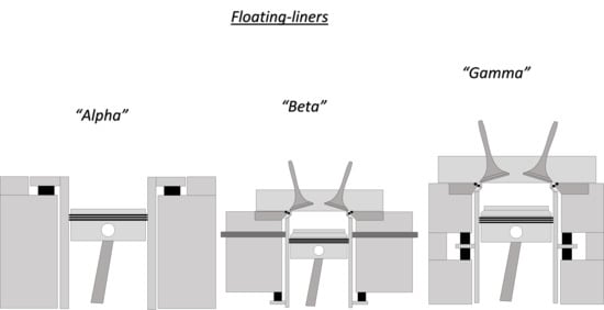
5. Discussion: Major Configurations of Floating-Liner Techniques

In overcoming the design challenges discussed above, researchers have adopted a range of designs in floating-liner equipment [14,35,46,54,55,56,59,60,61,62,63,64]. In this section, various approaches to designs have been examined and classified into three categories named Alpha, Beta, and Gamma.

5.1. Alpha

This design is the simplest form of a floating-liner. It consists of a motorized system comprising a cranking mechanism, cylinder liner and the cylinder block without a cylinder head. Three-axis force sensors support the liner with respect to the cylinder block, and lateral support is not usually required. The force is measured axially and radially via the 3-axis force sensors, and the noise effect of piston slaps can be deduced from the signals. Figure 16 shows a simple arrangement of this configuration.

5.1.1. Applications

Cater et al. [59] designed a floating cylinder liner apparatus consisting of a 318 cc, 10-horsepower engine with one cylinder of bore 7.94 cm and a stroke of 6.43 cm. The engine was driven with a DC motor of 2.2 kW with variable speed. A set of pulleys were used to connect the motor to the engine with a speed reduction of 14:3. A digital encoder was utilized to record the angular position, so the position of the piston could be determined. The cylinder block, including the cylinder liner, was suspended by two piezoelectric 3-axis force sensors to measure the forces of the friction and the thrust force of the piston.
Tamura et al. [60] also developed a motored apparatus of this type to investigate the shear rate effects of the lubricating oils on friction. Two load cells were mounted at the top of the arrangement between the liner and the cylinder block. The lubricating oil was heated by external heaters and circulated in the engine by an electric pump. The temperature of the liner was monitored utilizing thermocouples, fitted onto the cylinder liner. An induction-based crank-angle sensor was used to detect TDC.

5.1.2. Advantages

  • Simple design.
  • Easy access to the liner and the piston, so it could be used effectively with interchangeable liners, pistons and piston rings.
  • Inexpensive when compared with the other designs.
  • Able to be based on a wide range of reciprocating engines due to its simplicity, as a cranking mechanism and a liner are only the main components needed from an engine to build this type of floating-liner.
It can be heated to investigate operation at elevated temperatures.

5.1.3. Disadvantages

  • Cannot be pressurized.
  • Cannot be fired.

5.2. Beta

In this design, the existing liner is separated from the engine block and usually supported laterally using stoppers. These stoppers are placed either near the top or at the top and the base, as shown in Figure 17 and Figure 18, respectively. The approach can be applied to either water-cooled or air-cooled engines. The main function of the lateral stopper is to restrict the motion of the floating-liner radially while allowing its motion axially to eliminate the effect of piston slaps.
The combustion chamber pressure can be maintained by many alternative approaches, such as by balancing the combustion chamber and gas leakage forces, using a labyrinth seal or O-rings, preventing gas access to the top of the cylinder by using a cylinder head extension, or by placing the cylinder head inside the liner with very fine clearance. The number of force sensors used to measure friction mainly depends on their stiffness and the target natural frequency of the apparatus. Higher natural frequencies will enable measurement of friction at higher engine speeds.
This design requires more modifications if the engine is water-cooled, as it requires sealing of the water between the liner and the block while maintaining the linear motion of the liner.

5.2.1. Applications

(Yun and Kim, 1993) [54] developed this kind of floating-liner system in a four-cylinder, 2467 cm3, Indirect Injection (IDI) Diesel engine. The liner was designed to require less installation space to reduce system noise due to slap and thrust forces. The liner had four strain gauges attached to both faces of the base lip of the cylinder liner to measure the friction force. This was done to eliminate the effect of temperature and forces due to piston thrust and slap. The strain gauges were arranged in a way that all forces and moments due to lateral movement would generate equal values yet opposite in sign. Accordingly, they cancel each other, and the vertical movement can be measure solely. An O-ring was used to seal the combustion gases, and an annular copper plate was employed to protect the O-ring from the hot combustion gases.
The natural frequency was measured to be 884 Hz. So, a low pass filter of 700 Hz was applied to all the measured data to eliminate the effect of the resonance from the signals. The engine block vertical vibrations were measured at each crank angle by a piezoelectric accelerometer to correct the measured friction force. The force generated on the floating-liner due to engine vibration is the mass of the liner multiplied by the acceleration of the engine vertical vibration. So, to eliminate the effect of the engine vibration, the product of liner mass and engine vertical-acceleration is subtracted from the measured force by the strain gauges to get the net friction force.
Urabe et al. [35] used the floating cylinder liner to examine the lubrication and investigate abnormal wear when using exhaust gas recirculation (EGR).
Law et al. [46] built a floating-liner engine based on a single-cylinder version of existing parts from a Ford diesel engine with an 86mm bore and a 94.6mm stroke. The engine was motored with a 20 kW motor. The liner was supported by four horizontal rose-jointed struts at the top and with a flexible diaphragm at the bottom. Two load cells were used to support the liner at is base to measure the friction force. For sealing, a labyrinth device was employed. An air injection system was used to compensate for the losses of the air due to blow-by or escape of air through the labyrinth seal. Oil-heaters were employed to heat the engine and the liner. The temperature was measured by six thermocouples on the cylinder liner. This test apparatus was used to investigate liner features, such as surface roughness, honing angle, ring design, and others, that influence friction.
Liao et al. [61] studied the lubrication characteristics of a twin land oil control ring in a motored floating-liner engine. The liner used in this study had two piezoelectric sensors placed at the base of the liner to measure the friction force. A thermocouple placed near the middle of the cylinder liner measured temperature. Stoppers were used to restrict the lateral movement of the liner. Although the design of this floating-liner originally included the cylinder head, in this research, the cylinder head was removed. The crankcase was open to prevent the crankcase pressure affecting the readings of the piezoelectric sensors. Figure 19 shows the results of floating-liner engine experiments with same test conditions; however, the crankcase was opened to the atmosphere one time (red trace) and closed the other time (blue trace). The pressure variation in the crankcase affected the reading of the load sensor. This demonstrates the importance of taking the crankcase pressure into account in measuring the friction. The factors that affect the friction of twin land oil control rings were studied, such as ring land width, cylinder temperature, ring tension, and engine speed. This floating-liner engine was able to generate instantaneous Stribeck Curves that cover all three lubrication regimes with the combination of varying engine speed, oil temperature, and ring tension/land-width. The same device was used by Westerfield [62] to study the contribution of different aspects of piston skirt, such as skirt patterns, piston skirt profiles, and roughness of piston skirt coating. Results have shown that the reduction of the roughness of piston skirt reduces friction losses. Nevertheless, friction can also be reduced by optimizing skirt profile.
Sato et al. [55] developed a floating cylinder liner device using the cylinder block as the floating part instead of the liner. A motorcycle engine was used as a basis for the apparatus. The cylinder block was supported by a customized outer block employing four load washers. The block was also supported by lateral stoppers, as shown in Figure 20.
The sealing method that was adopted was first introduced by Furuhama et al. [33]. Since the engine was originally air-cooled, the air was used to cool the engine by blowing it between the outer block and the cylinder block. To eliminate the effect of the crankcase pressure on the load sensors, the pressure in the crankcase was measured and used to correct the friction measurements. Furuhama et al. used this apparatus to investigate the frictional waveform under firing conditions.
Westerfield et al. [56] used a floating cylinder liner device to study two types of oil control ring: the twin-land oil control ring and the three-piece oil control ring. The apparatus consisted of a floating-liner that was connected to a host cylinder with two load sensors. The devices had two lateral supports to eliminate the piston thrust in the radial direction. The study included the effect of land width and spring tension for the twin-land oil control ring. It also included different liner surfaces for both types of oil control rings.

5.2.2. Advantages

  • The arrangement can be used in firing conditions.
  • Due to the sensors being placed at the base of the liner, the arrangement offers space to modify the head for sealing.
  • Motoring of the system is possible.
  • Motoring can involve pressurization and heated lubricants and/or external liner heaters.

5.2.3. Disadvantages

  • The arrangement requires a high level of modification of the engine, especially the engine block and cylinder head for sealing gas pressure.
  • The system requires lateral restriction of the motion of the liner.
  • The arrangement is relatively difficult to assemble and disassemble to change the liner, piston rings, etc.

5.3. Gamma

In these arrangements, the supporting cylinder block is usually manufactured, as well as the liner. This allows several novel configurations, including placing the force-measuring sensors at a lip in the middle of the liner, as shown in Figure 21. The force sensors that are used in this type are commonly 3-axis force sensors eliminating the need for the lateral supports and allowing piston slap and thrust measured. The approach can be used with both air-cooled and water-cooled engines.

5.3.1. Applications

O’Rourke et al. [63] built a research-grade floating cylinder liner using an S&S V-Twin, two-cylinder engine. The main reason for choosing this engine was the high accessibility of the cylinder block. One of the cylinder blocks was stripped down and replaced by a manufactured cylinder block to include the floating-liner. In this arrangement, four three-axis piezoelectric transducers were used to measure the force in the axial and lateral direction. Band heaters were fitted to heat the liner to simulate the combustion temperature, and external heaters also heated the lubricant. The liner was sealed by 2 O-rings at the top and the bottom. An electric motor of 18.6 kW drove the engine.
Winklhofer et al. [64] developed a floating-liner with pistons that could be changed without interfering with the sensor package. In this design, the liner and the cooling jacket floated and were connected to the cylinder block by four piezoelectric sensors that measured the friction force between the piston assembly and the liner. Radial seals were used between the liner and the cylinder head. Winklhofer et al. [14] further developed this floating-liner apparatus to measure the effect of the offset between the piston and crankshaft by introducing an offset between the piston and the crankshaft. This is accomplished by moving the cylinder liner and head assembly to the side and having an oval-shaped crankcase bore.
Gore et al. [44] developed a single-cylinder floating-liner based on a motorbike engine (Honda CRF450R). They conducted some representative tests with the cylinder head on to include chamber pressure. The cylinder block and the liner were manufactured especially to be adapted in this design. Six small Quartz piezoelectric sensors were placed at the middle lip on both upper and lower faces, three on each face at 120° separations. Labyrinth seal was used to seal the air inside the combustion chamber. Gore et al. [45] used the same floating-liner described previously to measure the cyclic friction under controlled conditions. The test conditions included both motorized and fired conditions.

5.3.2. Advantages

  • The arrangement does not require lateral support.
  • The system can be used in motoring and firing condition.
  • The arrangement can be pressurized and heated using lubrication oil and/or external liner heaters.

5.3.3. Disadvantages

  • The approach requires manufacturing or modification of both the liner and cylinder block.
  • Harder to be used in firing condition as the liner and the cylinder block are manufactured.
  • It is less convenient to use the approach with pre-manufactured cylinder liners.

6. Conclusions

This paper has critically reviewed the main approaches adopted in the design of floating-liner systems for piston assembly friction measurement in internal combustion (IC) engines and highlighted the main approaches to several factors, including sealing the floating system, balancing the gas pressures on the floating system, correcting data contaminated by vibration, and issues when using common sensors. It can be concluded:
  • With the advancement in today’s machining precision, annular/force balancing sealing is a promising method of sealing the combustion chamber.
  • Gas chamber pressure balancing can be an intuitive way to avoid modifying piston crown, leading to using many stock pistons for research without modifying them.
  • Designing of floating-liner system mainly depends on the nature of the study required to be conducted.
  • Non-pressurized (such as Alpha) floating-liner systems are simple to build and operate. However, they do not replicate the full range of behavior of the mechanical and fluid components in the piston assembly or the effects resulting from combustion and, therefore, represent the behavior of operating engines in a limited way.
  • Pressurized systems (such as Beta and Gamma) are becoming increasingly common, but their design remains challenging. They have the potential to replicate the full spectrum of phenomena that arise in firing engines during service.
  • Firing floating-liners are the most challenging in design and operation, especially regarding excessive engine vibrations, sealing the combustion chamber, and the instrumentation used. However, it gives the most realistic results if it is built properly.
  • Pressurized and heated floating-liners are good alternatives and have fewer issues than the firing ones, yet can give a good simulation to the firing conditions.
  • A range of standardized approaches, reviewed in this paper, can be adopted to develop effective designs of both pressurized and non-pressurized floating-liner arrangements.

7. Proposals for Further Work

Friction measurement systems are generally used for one of several main purposes, these being: fundamental studies into the principles of lubrication of piston assembly components, comparative evaluation of changes in the design of engine components in association with geometry, and surface finish/coatings or lubricant formulation.
The study points towards several elements of future work:
  • It will be of value to compare the output of established piston assembly lubrication models with detailed data collected from floating-liner systems to test the level of compatibility between accurate experimental friction measurements and well established (industry standard) simulation tools.
  • It may be of more value to evaluate power loss from friction data, rather than to present friction data in its own right, as power loss data is more meaningful in a broader context.
  • It is clearly possible to incorporate other types of tribological sensor in floating-liner systems, to evaluate oil consumption, lubricating film thickness, cylinder temperature distributions, etc. Such multi-sensor systems will have considerable value in commercial settings.
  • Design improvements can only be reliably detected at different sites if the same test equipment is used for all evaluations, so it may make sense to identify a standardized design of floating-liner systems so that direct comparisons can be made between data collected by different organizations.

Author Contributions

Conceptualization, A.M.Y.; methodology, A.M.Y., E.H.S., I.S. and G.C.; writing—original draft preparation, A.M.Y., G.C., I.S., E.H.S., and H.R.; writing—review and editing, A.M.Y., G.C., I.S., E.H.S., and H.R.; visualization, A.M.Y.; supervision, G.C., E.H.S. and I.S. All authors have read and agreed to the published version of the manuscript.

Funding

This research received no external funding.

Institutional Review Board Statement

Not applicable.

Informed Consent Statement

Not applicable.

Data Availability Statement

Not applicable.

Conflicts of Interest

The authors declare no conflict of interest.

Appendix A

Plate and loading constants as used in the reaction force equations for an annular plate with an evenly distributed load. The lengths a and b correspond to the inner and outer radial coordinates of the plate.
C 2 = 1 4 [ 1 ( b a ) 2 ( 1 + 2 ln a b ) ] ,
C 3 = b 4 a [ { ( b a ) 2 + 1 } ln a b + ( b a ) 2 1 ] ,
C 5 = 1 2 [ 1 ( b a ) 2 ] ,
C 6 = b 4 a [ ( b a ) 2 1 + 2 ln a b ] ,
L 11 = 1 64 { 1 + 4 ( b a ) 2 5 ( b a ) 4 4 ( b a ) 2 [ 2 + ( b a ) 2 ] ln a b } ,
L 14 = 1 16 { 1 ( b a ) 4 4 ( b a ) 2 ln a b } .

References

  1. Fontaras, G.; Samaras, Z. On the way to 130 g CO2/km—Estimating the future characteristics of the average European passenger car. Energy Policy 2010, 38, 1826–1833. [Google Scholar] [CrossRef]
  2. Holmberg, K.; Andersson, P.; Erdemir, A. Global energy consumption due to friction in passenger cars. Tribol. Int. 2012, 47, 221–234. [Google Scholar] [CrossRef]
  3. Jost, H.P. Tribology Micro & Macro Economics: A Road to Economic Savings. Tribol. Lubr. Technol. 2005, 61, 18–22. [Google Scholar]
  4. Holmberg, K.; Erdemir, A. Global impact of friction on energy consumption, economy and environment. FME Trans. 2015, 43, 181–185. [Google Scholar]
  5. Fessler, R.R.; Fenske, G.R. Multiyear Program Plan: Reducing Friction and Wear in Heavy Vehicles. 1999. Available online: https://www.osti.gov/biblio/771210 (accessed on 16 January 2021).
  6. Ting, L.L. A Review of Present information on Piston Ring Tribology. SAE Trans. 1985, 94, 1135–1146. [Google Scholar]
  7. Patton, K.J.; Nitschke, R.G.; Heywood, J.B. Development and Evaluation of a Friction Model for Spark-Ignition Engines. SAE Trans. 1989, 98, 1441–1461. [Google Scholar]
  8. Kovach, J.T.; Tsakiris, E.A.; Wong, L.T. Engine Friction Reduction for Improved Fuel Economy; SAE: Warrendale, PA, USA, 1982. [Google Scholar]
  9. Koch, F.; Geiger, U.; Hermsen, F. PIFFO Piston Friction Force Measurements during Engine Operation; SAE: Warrendale, PA, USA, 1996. [Google Scholar]
  10. Richardson, D.E. Review of Power Cylinder Friction for Diesel Engines. J. Eng. Gas Turbines Power 2000, 122, 506–519. [Google Scholar] [CrossRef]
  11. Betz, G.; Gabele, H.; Assmus, H.O. Friction Power and Noise Behaviour of the Piston Assembly. In Proceedings of the Second International Conference on Combustion Engines–Reduction of Friction and Wear, London, UK, 19–20 September 1989; pp. 35–58. [Google Scholar]
  12. Goenka, P.K.; Meernik, P.R. Lubrication analysis of piston skirts. SAE Trans. 1992, 101, 886–895. [Google Scholar]
  13. Harikumar, Y.; Mahadevan, R.; Muralitharan, N.; Manivasagam, S. Rengarajan Predictive Technique Approach for Diesel Engine Piston Ring Pack Design Optimization and Experimental Verification; SAE: Warrendale, PA, USA, 2005. [Google Scholar]
  14. Winklhofer, E.; Loesch, S.; Satschen, S.; Thonhauser, B. Reduction of Friction Losses by Means of Cylinder Liner Offset in a Floating Liner Single Cylinder Engine. Int. J. Automot. Eng. 2018, 9, 304–309. [Google Scholar] [CrossRef] [Green Version]
  15. Mike, T.N.; Dennis, N.A.; Donald, J.P.; Simon, C.T.; Spyros, I. Tseregounis Overview of Techniques for Measuring Friction Using Bench Tests and Fired Engines. SAE Trans. 2000, 109, 890–900. [Google Scholar]
  16. Nagano, Y.; Ito, A.; Okamoto, D.; Yamasaka, K. A Study on the Feature of Several Types of Floating Liner Devices for Piston Friction Measurement; SAE: Warrendale, PA, USA, 2019. [Google Scholar]
  17. Nagar, P.; Miers, S. Friction between Piston and Cylinder of an IC Engine: A Review; SAE: Warrendale, PA, USA, 2011. [Google Scholar]
  18. Uras, H.M.; Patterson, D.J. Effect of Some Piston Variables on Piston and Ring Assembly Friction. SAE Trans. 1987, 96, 16–26. [Google Scholar]
  19. Uras, H.M.; Patterson, D.J. Measurement of Piston and Ring Assembly Friction Instantaneous IMEP Method; SAE: Warrendale, PA, USA, 1983. [Google Scholar]
  20. Uras, H.M.; Patterson, D.J. Oil and Ring Effects on Piston-Ring Assembly Friction by the Instantaneous IMEP Method; SAE: Warrendale, PA, USA, 1985. [Google Scholar]
  21. Uras, H.M.; Patterson, D.J. Effect of Some Lubricant and Engine Variables on Instantaneous Piston and Ring Assembly Friction; SAE: Warrendale, PA, USA, 1984. [Google Scholar]
  22. Mufti, R.A.; Priest, M. Experimental Evaluation of Piston-Assembly Friction under Motored and Fired Conditions in a Gasoline Engine. J. Tribol. 2005, 127, 826–836. [Google Scholar] [CrossRef]
  23. Mufti, R.A. Total and Component Friction in a Motored and Firing Engine. Ph.D. Thesis, University of Leeds, Leeds, UK, 2004. [Google Scholar]
  24. Hawkes, C.J. Friction of piston rings. Trans. Ne Coast Inst. Civ. Engrs. Shipbuild. 1936, 52, 49. [Google Scholar]
  25. Barros, A.F. Piston ring friction-rig measurements with low viscosity oils. J. Inst. Pet. 1960, 46, 1. [Google Scholar]
  26. Eilon, S.; Saunders, O.A. A study of piston-ring lubrication. Proc. Inst. Mech. Eng. 1957, 171, 427–462. [Google Scholar] [CrossRef]
  27. Stanton, T.E. The friction of pistons and piston rings. Engineer 1925, 139, 72. [Google Scholar]
  28. Tischbein, H.W. The Friction of Piston Rings. NACA Technical Memorandums No. 1069. 1945. Available online: https://digital.library.unt.edu/ark:/67531/metadc63676/ (accessed on 16 January 2021).
  29. Forbes, J.E.; Taylor, E.S. A Method for Studying Piston Friction. NACA Report; 1943. Available online: https://ntrs.nasa.gov/citations/19930093197 (accessed on 16 January 2021).
  30. Leary, W.A.; Jovellanos, J.U. A Study of Piston and Ring Friction. NACA Report. 1944. Available online: https://digital.library.unt.edu/ark:/67531/metadc61997/m1/8/ (accessed on 16 January 2021).
  31. Livengood, J.C.; Wallour, C. A Study of Piston-Ring Friction. 1947. Available online: https://digital.library.unt.edu/ark:/67531/metadc55407/ (accessed on 16 January 2021).
  32. Rogowski, A.R. Method of Measuring the Instantaneous Friction of Piston Rings in a Firing Engine; SAE: Warrendale, PA, USA, 1961. [Google Scholar]
  33. Furuhama, S.; Takiguchi, M. Measurement of Piston Frictional Force in Actual Operating Diesel Engine. SAE Trans. 1979, 88, 2896–2914. [Google Scholar]
  34. Nakayama, K.; Yasutake, Y.; Takiguti, M.; Furuhama, S. Effect of Piston Motion on Piston Skirt Friction of a Gasoline Engine; SAE: Warrendale, PA, USA, 1997. [Google Scholar]
  35. Urabe, M.; Tomomatsu, T.; Ishiki, K.; Takiguchi, M.; Someya, T. Variation of Piston Friction Force and Ring Lubricating Condition in a Diesel Engine with EGR; SAE: Warrendale, PA, USA, 1998. [Google Scholar]
  36. Teraguchi, S.; Suzuki, W.; Takiguchi, M.; Sato, D. Effects of Lubricating Oil Supply on Reductions of Piston Slap Vibration and Piston Friction. SAE Trans. 2001, 110, 579–584. [Google Scholar]
  37. Kikuchi, T.; Ito, S.; Nakayama, Y. Piston friction analysis using a direct-injection single-cylinder gasoline engine. JSAE Rev. 2003, 24, 53–58. [Google Scholar] [CrossRef]
  38. Madden, D.; Kim, K.; Takiguchi, M. Part 1: Piston Friction and Noise Study of Three Different Piston Architectures for an Automotive Gasoline Engine. SAE Trans. 2006, 115, 257–263. [Google Scholar]
  39. Kim, K.; Shah, P.; Takiguchi, M.; Aoki, S. Part 3: A Study of Friction and Lubrication Behavior for Gasoline Piston Skirt Profile Concepts; SAE: Warrendale, PA, USA, 2009. [Google Scholar]
  40. Cerrato, R.; Gozzelino, R. Ricci A Single Cylinder Engine for Crankshaft Bearings and Piston Friction Losses Measurement; SAE: Warrendale, PA, USA, 1984. [Google Scholar]
  41. Mollenhauer, K.; Bruchner, K. Contribution to the Determination of the Influence of Cylinder Pressure and Engine Speed on Engine Friction. MTZ 1980, 41, 265–268. [Google Scholar]
  42. Sherrington, I.; Smith, E.H. The measurement of piston-ring friction by the floating liner method. Imeche. Exp. Methods Engine Res. Dev. 1988, 1–11. [Google Scholar]
  43. Richez, M.F.; Constans, B.; Winquist, K. Paper V(ii) Theoretical and experimental study of ring-liner friction. In Tribology of Reciprocating Engines; Dowson, D., Taylor, C.M., Godet, M., Berthe, D., Eds.; Elsevier Ltd.: Amsterdam, The Netherlands, 1993; pp. 122–131. [Google Scholar]
  44. Gore, M.; Howell-Smith, S.J.; King, P.D.; Rahnejat, H. Measurement of In-Cylinder Friction Using the Floating Liner Principle. In Proceedings of the ASME 2012 Internal Combustion Engine Division Spring Technical Conference, Torino, Piemonte, Italy, 6–9 May 2012; American Society of Mechanical Engineers Digital Collection: New York City, NY, USA, 2012; pp. 901–906. [Google Scholar]
  45. Gore, M.; Theaker, M.; Howell-Smith, S.; Rahnejat, H.; King, P.D. Direct measurement of piston friction of internal-combustion engines using the floating-liner principle. Proc. Inst. Mech. Eng. Part D J. Automob. Eng. 2014, 228, 344–354. [Google Scholar] [CrossRef] [Green Version]
  46. Law, T.; MacMillan, D.; Shayler, P.J.; Kirk, G.; Pegg, I.; Stark, R. A New Floating-Liner Test Rig Design to Investigate Factors Influencing Piston-Liner Friction; SAE: Warrendale, PA, USA, 2012. [Google Scholar]
  47. Furuhama, S.; Sasaki, S. New device for the measurement of piston frictional forces in small engines. SAE Trans. 1983, 781–792. [Google Scholar]
  48. Clarke, D.G.; Sherrington, I.; Smith, E.H. Design Considerations for a ’Floating Liner’ Method of Measuring Piston/Piston Ring Friction in Internal Combustion Engines. In Proceedings of the Proc. of Eurotrib 89, 5th International Congress on Tribology, Helsinki, Finland, 14 June 1989; pp. 432–438. [Google Scholar]
  49. Clarke, D.G.; Sherrington, I.; Smith, E.H. The floating liner method applied to measure instantaneous piston assembly friction in a motored engine. In Proceedings of the Proc. of Nordtrib 90, 4th Nordic Symposium on Tribology, Lubrication, Friction and Wear, Hirthals, Denmark, 10–13 June 1990; Technical University of Denmark Copenhagen, Denmark: Hirtshals, Denmark, 1990; pp. 473–483. [Google Scholar]
  50. Young, W.C.; Budynas, R.G.; Sadegh, A.M. Roarks Formulas for Stress and Strain; McGraw-Hill’s AccessEngineering; McGraw Hill Book Company: New York City, NY, USA, 2011. [Google Scholar]
  51. Rahnejat, H. Multi-Body Dynamics: Vehicles, Machines and Mechanisms; Professional Engineering Publisher: London, UK, 1998. [Google Scholar]
  52. Ha, K. Liner Mounting Structure for Measuring Piston Friction. US6487999B2, 3 December 2002. [Google Scholar]
  53. Ha, K.; Kim, J.; Cho, M.; Oh, D.Y. Development of Piston Friction Force Measurement System; SAE: Warrendale, PA, USA, 2002. [Google Scholar]
  54. Yun, J.E.; Kim, S.S. New Device for Piston-Ring Assembly Friction Force Measurement in IDI Diesel Engine. JSME Int. J. Ser. B Fluids Therm. Eng. 1993, 36, 723–729. [Google Scholar] [CrossRef] [Green Version]
  55. Sato, T.; Kurita, H.; Ito, A.; Iwasaki, H. Friction Measurement of Al-17%Si Monolithic Cylinder with Using Newly Developed Floating Liner Device. SAE Int. J. Engines 2014, 8, 135–142. [Google Scholar] [CrossRef]
  56. Westerfield, Z.; Liu, Y.; Kim, D.; Tian, T. A Study of the Friction of Oil Control Rings Using the Floating Liner Engine. SAE Int. J. Engines 2016, 9, 1807–1824. [Google Scholar] [CrossRef]
  57. Kirner, C.; Halbhuber, J.; Uhlig, B.; Oliva, A.; Graf, S.; Wachtmeister, G. Experimental and simulative research advances in the piston assembly of an internal combustion engine. Tribol. Int. 2016, 99, 159–168. [Google Scholar] [CrossRef]
  58. Ishiki, K.; Oshida, S.; Takiguchi, M.; Urabe, M. A Study of Abnormal Wear in Power Cylinder of Diesel Engine with EGR Wear Mechanism of Soot Contaminated in Lubricating Oil; SAE: Warrendale, PA, USA, 2000. [Google Scholar]
  59. Cater, M.; Bolander, N.W.; Sadeghi, F. A Novel Suspended Liner Test Apparatus for Friction and Side Force Measurement with Corresponding Modeling; SAE: Warrendale, PA, USA, 2006. [Google Scholar]
  60. Tamura, K.; Kasai, M.; Nakamura, Y.; Enomoto, T. Influence of Shear-Thinning of Polymer-Containing Engine Oils on Friction at the Piston Ring-Cylinder Liner Interface; SAE: Warrendale, PA, USA, 2013. [Google Scholar]
  61. Liao, K.; Chen, H.; Tian, T. The Study of Friction between Piston Ring and Different Cylinder Liners using Floating Liner Engine Part 1; SAE: Warrendale, PA, USA, 2012. [Google Scholar]
  62. Westerfield, Z.; Totaro, P.; Kim, D.; Tian, T. An Experimental Study of Piston Skirt Roughness and Profiles on Piston Friction Using the Floating Liner Engine; SAE: Warrendale, PA, USA, 2016. [Google Scholar]
  63. O’Rourke, B.; Stanglmaier, R.; Radford, D. Development of a Floating-Liner Engine for Improving the Mechanical Efficiency of High Performance Engines; SAE: Warrendale, PA, USA, 2006. [Google Scholar]
  64. Winklhofer, E.; Loesch, S.; Satschen, S. High Precision Piston to Liner Friction Measurement. In Proceedings of the JSAE Annual Congress Proceedings, Pacifico Yokohama, Japan, 25–27 May 2016; pp. 1864–1869. [Google Scholar]
Figure 1. Forces acting on the piston.
Lubricants 09 00010 g001
Figure 2. Separated bore from the cylinder block.
Lubricants 09 00010 g002
Figure 3. O-ring is placed in a groove to seal the combustion chamber.
Lubricants 09 00010 g003
Figure 4. Cylinder head is inserted inside the liner.
Lubricants 09 00010 g004
Figure 5. Gas leak through the labyrinth seal pushing the liner down, adapted from Reference [44].
Lubricants 09 00010 g005
Figure 6. Schematic diagram of a floating cylinder liner with an annular plate sealing arrangement.
Lubricants 09 00010 g006
Figure 7. Annular plate with evenly distributed load (q), inner and outer edges fixed. The vertical reaction forces (Qa and Qb) are shown.
Lubricants 09 00010 g007
Figure 8. Force balancing using modified geometry of cylinder liner.
Lubricants 09 00010 g008
Figure 9. Upper detail of a floating-liner, highlighting the leakage galley, vented to atmosphere.
Lubricants 09 00010 g009
Figure 10. A novel design using a pressure compensation chamber to balance the liner, adapted from Reference [53].
Lubricants 09 00010 g010
Figure 11. Typical signal without noise.
Lubricants 09 00010 g011
Figure 12. Inertia forces due to the vibration of the engine block, adapted from Reference [54].
Lubricants 09 00010 g012
Figure 13. Sealing and balancing the liner, adapted from Reference [54].
Lubricants 09 00010 g013
Figure 14. Friction force at 30 Nm and 72 Nm engine load, adapted from Reference [45].
Lubricants 09 00010 g014
Figure 15. Friction force at different engine loads (300, 600, and 900 kPa), adapted from Reference [55].
Lubricants 09 00010 g015
Figure 16. Floating-liner apparatus without cylinder head.
Lubricants 09 00010 g016
Figure 17. Liner is fixed laterally via two lateral stoppers.
Lubricants 09 00010 g017
Figure 18. Liner is fixed laterally via four lateral stoppers.
Lubricants 09 00010 g018
Figure 19. The effect of the crankcase pressure on the friction measured, adapted from Reference [61].
Lubricants 09 00010 g019
Figure 20. Cylinder head is protruded inside the cylinder liner, adapted from [55].
Lubricants 09 00010 g020
Figure 21. Mid-lip liner, adapted from Reference [63].
Lubricants 09 00010 g021
Table 1. Typical values for peak friction forces measured in a range of firing engines.
Ref.Cylinder Capacity (L)Engine LoadEngine Speed (rev min−1)Natural Frequency (Hz)Maximum Friction (N)Instrumentation Used
[55]0.11
0.11
0.11
300 kPa (IMEP)
500 kPa (IMEP)
900 kPa (IMEP)
3000
3000
3000
-50
100
130
Load washers, crankcase pressure sensor, thermocouple near the cylinder bore surface
[45]0.449
0.449
30 Nm
72 Nm
2500
2500
-125
370
Quartz piezoelectric miniature force transducers model 9131B, Kistler Holding AG, 4 accelerometers
[56]0.496200 kPa (IMEP)1500-35piezoelectric sensors, thermocouple on the liner
[57]0.500600 kPa (IMEP)2000-65-
[54]0.619
0.619
0.619
No Load
No Load
No Load
1000
1500
2000
25
25
25
280
270
260
Strain gauge M-M, WK-06-125-AD-350, Pizeo-accelerometer (Brul & kjaer 4393) sensor
[54]0.619
0.619
0.619
100% Load
100% Load
100% Load
1000
1500
2000
25
25
25
320
250
270
Strain gauge M-M, WK-06-125-AD-350, Piezo-accelerometer (Brul & kjaer 4393) sensor
[35]1.05250% load2000-280Load washer
[58]1.05275% load1200-280Load washer
Publisher’s Note: MDPI stays neutral with regard to jurisdictional claims in published maps and institutional affiliations.

