Abstract
Energy efficiency and functional reliability are the two key requirements in the design of high-performance transmissions. Therefore, a representative analysis replicating real operating conditions is essential. This paper presents the thermoelastohydrodynamic lubrication (TEHL) of meshing spur gear teeth of high-performance racing transmission systems, where high generated contact pressures and lubricant shear lead to non-Newtonian traction. The determination of the input contact geometry of meshing pairs as well as contact kinematics are essential steps for representative TEHL. These are incorporated in the current analysis through the use of Lubricated Loaded Tooth Contact Analysis (LLTCA), which is far more realistic than the traditional Tooth Contact Analysis (TCA). In addition, the effects of lubricant and flash surface temperature rise of contacting pairs, leading to the thermal thinning of lubricant, are taken into account using a thermal network model. Furthermore, high-speed contact kinematics lead to shear thinning of the lubricant and reduce the film thickness under non-Newtonian traction. This comprehensive approach based on established TEHL analysis, particularly including the effect of LLTCA on the TEHL of spur gears, has not hitherto been reported in literature.
1. Introduction
Spur gears are used in a multitude of engineering applications, including but not limited to automotive transmissions. There is a growing volume of legislation, stringent directives, and regulated targets to reduce harmful emissions from all machinery, particularly from road transport, thus requiring ever-improved energy-efficient transmissions. It is also important to improve noise, vibration, and harshness (NVH) refinement of all gearing systems, as this is another customer-demanded attribute. Additionally, the structural integrity and durability of all mechanical components such as gearing and bearings is of primary concern, particularly with the ever-harsher operating conditions (increased loading, faster contact kinematics, and elevated temperatures). It has been shown that operating conditions for transmissions affect their energy consumption and NVH performance, which are interlinked and often require contradictory methods of palliation [1]. The current investigation focuses on the transmission efficiency and structural integrity of spur gears of high-performance vehicles.
It is now well-established that some degree of traction is needed to transmit power through gear interactions. However, beyond a certain limit, excess traction can lead to power loss throughout a typical meshing cycle [2,3,4]. Therefore, it is important to develop techniques to predict the generated friction, thus accurately assessing the power losses of a transmission system. Petry-Johnson et al. [5] have shown the influence of surface roughness and a formed thin lubricant film in gear teeth pair conjunctions upon generated friction and eventually the efficiency of a gear box operating at speeds up to 10,000 rpm. Li and Kahraman [6] developed a tribodynamic model to predict friction throughout a meshing cycle of a spur gear pair. Using theoretical tooth profiles, the authors showed the essential coupling between gear dynamics and tribology of contact throughout the meshing cycle. There have been other contributions with a focus on spur gear pairs [7,8,9,10].
Two key factors influence the structural integrity of teeth–pair contacts. These are the induced root stresses and contact surface defects caused by the generated sub-surface stresses. The latter form part of the current investigation, as they are more of concern for high-performance transmissions based upon spur gears. It has been shown that the onset of fatigue spalling is a crucial problem in spur gears and is generally induced by generated high sub-surface shear stresses [11,12,13,14]. However, an important issue is the proper consideration for the determination of real contact surface geometry and kinematics, as well as an accurate lubrication model, which are the main contributions of the current paper.
Traditionally, the contact parameters used for the tribological studies are obtained using Tooth Contact Analysis (TCA) [1,15,16,17,18]. However, the traditional TCA approach assumes perfect geometry of the contacting teeth under dry contact conditions. Consequently, surface defects from manufacturing processes or those caused during operation are not taken into account. Surface defects result in some changes in surface geometry and thus the contact conditions. Furthermore, gear teeth contacts are lubricated. These issues were recently taken into account by Oglieve et al. [19] in the reported Lubricated Loaded Tooth Contact Analysis (LLTCA) approach, which is adopted here. Details and procedures in this regard are highlighted in Section 2.1.
In order to evaluate the effect of LLTCA alone, the current study uses a standard one-dimensional non-Newtonian thermoelastohydrodynamic lubrication (TEHL) model of spur gear teeth pair with the instantaneous contact geometry and kinematics determined using the LLTCA, which is compared with the traditional TCA method. In this manner, the effect of LLTCA in a more accurate prediction of contact conditions becomes clear. Such an approach has not hitherto been reported in the literature.
2. Methodology
2.1. Tooth Contact Analysis (TCA) and Lubricated Loaded Tooth Contact Analysis (LLTCA)
There is a significant volume of work reported on gear design, research, and development, including in [20,21,22]. They show that the kinematics of gears, particularly for racing transmissions, require inclusion in the analysis [15,23]. Contact kinematics and geometry influence the contact loading of engaged teeth and consequently affect lubricant film formation, viscous shear, and friction. Therefore, there is a need for a TCA tool at the outset of any tribological study to provide the geometry and contact kinematics. The traditional TCA method was developed by Litvin and Fuentes [15] and Vijayakar [16], which are currently well-established and widely used. For this paper, the results from CALYX [16] are used to represent the TCA approach. As Oglieve et al. [19] showed, most FEA models solving complex contact problems such as the meshing gear teeth fail to consider lubricated surfaces, coupled with realistic surface geometry, which is measured directly using a coordinate measuring machine (CMM). The LLTCA approach aims to overcome this problem by introducing real geometry, coupled with realistic friction derived from a lubrication model. The key differences between TCA and LLTCA are summarized in Figure 1.
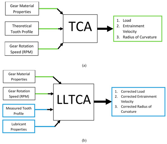
Figure 1.
Overview of (a) Tooth Contact Analysis (TCA) and (b) Lubricated Loaded Tooth Contact Analysis (LLTCA).
Figure 1 shows the main differences between LLTCA and TCA as the introduction of real surface geometry and lubricated contact by the former approach, as opposed to the ideally perfect and dry contact geometry by the latter. An overview on the process involved with LLTCA is shown in Figure 2. A comprehensive explanation of the process shown in Figure 2 has already been given in [19]. However, briefly, it can be noted that the process involves acquiring kinematic and kinetic data from the finite element analysis for each meshing point, and subsequently, friction in the contact is updated based on Equation (1). The results are entered into the software, and the process is repeated until the generated friction converges within an acceptable error tolerance.
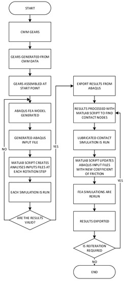
Figure 2.
LLTCA procedure flow chart [19].
Surface geometry used for the analysis is measured using a coordinate measuring machine (CMM) with a measurement sensitivity of . This allows for the inclusion of realistic surface defects/anomalies in the analysis. The coefficient of friction, fed back into the LLTCA’s FEA solver, is determined using a relationship provided by Evans and Johnson [24] as:
where:
and are the average contact pressure and characteristic (Eyring) shear stress of the lubricant, respectively. The density and specific heat of the gear material are denoted by and .
The lubricant film thickness at the center of the contact is predicted using the extrapolated oil film thickness formula of Chittenden et al. [25]:
where;
in which the non-dimensional parameters are , , and .
It is assumed that all gear teeth would undergo the same loading history during a typical meshing cycle. Thus, to reduce the burden of computation, only three consecutive teeth pair meshing cycles are modeled. This enables the development of a detailed model by setting the computational domain according to the trailing, current, and leading meshing teeth pairs only. Moreover, this investigation looks at a single meshing cycle. Ideally, to fully incorporate thermal effects, more than one cycle would need to be considered. In addition, a thermal network model coupled with the elastohydrodynamic lubrication (EHL) solver, which is presented later, can be embedded into the LLTCA method explained above in order to provide a more precise LLTCA analysis. However, this would be highly computationally resource-intensive and goes beyond the scope of the current investigation. Thus, the presented methodology is deemed as satisfactory.
The gear pair and operating conditions investigated by Oglieve et al. [19] are used in the current paper. The applied torque and rotational speed applied to the pinion was 312 Nm and 11,758 rpm, respectively [19]. Further details are outlined in Appendix A. It is noteworthy that a typical simulation based on the use of traditional TCA would take considerably less time than one adopting the new LLTCA approach. However, the results of LLTCA are much more representative of realistic conditions encountered in practice. Furthermore, refined and improved methods of computation can be developed to improve upon the computation times for the LLTCA. The most important results for the entire meshing cycle are the generated contact loads, as well as the speed of the entraining motion of the lubricant into the conjunction of a meshing teeth pair (i.e., the average speed of moving mating surfaces), as illustrated in Figure 3 and Figure 4, respectively. Figure 3b shows that LLTCA predicts an earlier engagement at the onset of meshing. Thus, the start and the end of a meshing cycle differs for the LLTCA and TCA methods.
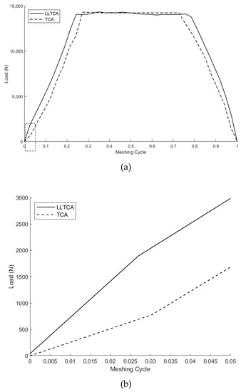
Figure 3.
(a) Contact force through the meshing cycle, (b) Detailed view [19].
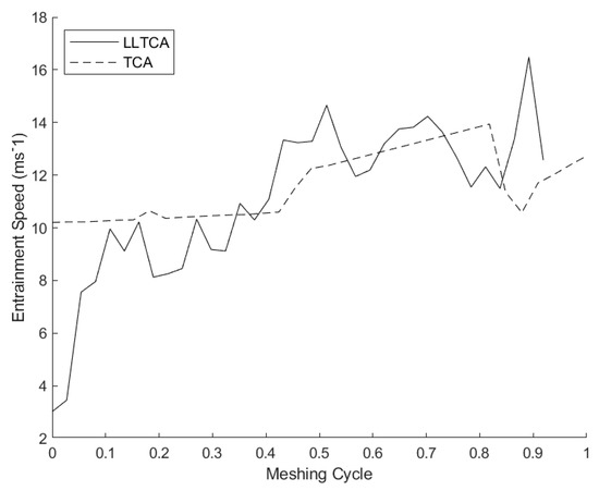
Figure 4.
Entrainment speed through the meshing cycle [19].
2.2. Elastohydrodynamic Lubrication (EHL)
High-performance spur gears exhibit contact pressures in excess of 1.2 GPa [18,22]. Therefore, the contact conditions pertain to a viscous–elastic (i.e., elastohydrodynamic) regime of lubrication. To obtain the pressure distribution and the corresponding film thickness, a simultaneous solution of Reynolds equation, elastic film shape, and lubricant rheological state equations is required.
In order to evaluate the effect of LLTCA alone, when compared with TCA, a well-established EHL analysis approach is followed.
The general form of Reynolds equation is:
where p, h, η, and ρ are the pressure, film thickness, lubricant dynamic viscosity, and density, respectively. U and V are surface velocities along the direction of entraining motion, x, and in the side-leakage direction, y, respectively. Olver [26] showed that spur gears generally run starved. Therefore, it can be assumed that the effect of lubricant side leakage would be negligible (i.e., V = 0). Therefore, a one-dimensional (1D) EHL solution would suffice. Furthermore, a quasi-static analysis of a meshing cycle is carried out. Therefore, the effect of squeeze film motion is neglected. A more comprehensive approach would require the effect of transience through the inclusion of squeeze film terms as an extension of the current analysis. This simplifies the Reynolds equation to:
The elastic film shape is given as:
where is the minimum film thickness (rigid clearance), s is the geometric profile of the teeth pair conjunction, and is the localized elastic deflection. It is apparent that the aspect ratio of the contact footprint would be high for spur gear teeth pair conjunctions. Therefore, for the case of an undeformed line contact, the profile of an equivalent solid near a semi-infinite elastic half-space becomes [27]:
The equivalent radius of curvature of the equivalent solid is taken from LLTCA. The general form of the localized elastic deflection is given by the elasticity potential equation as [28]:
Due to the high entrainment speed in very narrow conjunctions of gear contacts, it is necessary to consider a non-Newtonian viscosity model. To incorporate the effect of shear thinning, a similar approach to that of Paouris et al. [29] is undertaken, using the Havriliak and Negami [30] rheological model:
where the rest viscosity, , is taken at ambient pressure. The non-Newtonian function, , and shear rate, , are given as:
where , , and are the lubricant’s specific parameters found experimentally [30]. The shear rate is calculated using the lubricant film thickness at the center of the meshing teeth pair contact domain, .
For the majority of the meshing cycle (as shown later in the results), the contact undergoes a viscoelastic regime of traction [24], with lubricant viscosity being highly dependent on the generated contact pressures. Therefore, the Havriliak and Negami model [30] needs to be adjusted accordingly as:
where can be found using the following expression [31]:
Constants and are 6.31 × 10⁻⁵ and 1.9609 × 10⁸, respectively and the piezoviscosity index, Z, can be found from:
where the pressure–viscosity coefficient, , is usually obtained through experimental measurements.
As it will be shown later, some regions of the meshing cycle can be shear-independent. In these regions , resulting in lubricant viscosity being solely dependent on generated pressure (i.e., only Equation (14) is used).
The rest viscosity of the lubricant, , is temperature-dependent and is found using the Vogel’s equation [32]:
where, , , and are lubricant-specific constants found through measurements of viscosity at three different temperatures and through subsequent curve-fitting [33,34].
The effect of pressure and temperature on lubricant density is also taken into account as [35]:
where the density at ambient temperature and pressure is denoted by . Reference and bulk temperatures are denoted as and , respectively.
2.3. Tractive Analysis
To undertake analysis which is representative of in situ gear meshing conditions, it is essential to determine the prevailing regime of lubrication as well as the tractive conditions. To determine the regime of lubrication, the Greenwood chart is used [36]. Figure 5 shows the Greenwood chart, where the non-dimensional parameters are:
where , , and .
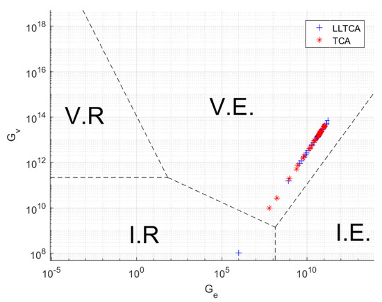
Figure 5.
Meshing cycle on the Greenwood Chart: I.R.—Isoviscous Rigid, V.R—Piezoviscous Rigid, I.E.—Isoviscous Elastic, V.E.—Piezoviscous Elastic [38].
Figure 5 shows the meshing cycle conditions according to the results of the current LLTCA and TCA analyses. It is clear that in both cases, piezoviscous-elastic (i.e., EHL) is the prevailing regime of lubrication. The meshing cycle commences with a tip-to-root teeth–pair interactions at low load with LLTCA, resulting in isoviscous rigid (i.e., hydrodynamics). It is often the case that the gear relief profile inhibits interactions in this region. Therefore, the current analysis ignores interactions in this region of the meshing cycle.
Often, the thin elastohydrodynamic films formed in the gear teeth meshing at high loads and/or shear cause viscoelastic traction with shear stress exceeding the limiting Eyring shear of the lubricant, which can subsequently reduce due to increased contact temperature [34]. One way of ascertaining any non-Newtonian viscous shear of the lubricant is to use the Deborah number, D [37] as:
where is the lubricant shear modulus and is obtained as [38]:
where is the atmospheric shear modulus of the lubricant and is the thermoviscosity index. Non-Newtonian viscoelastic traction is expected when .
Figure 6 shows the variation of Deborah number in the contact of a pair of spur gear teeth during a meshing cycle with contact geometry and kinematics determined through LLTCA and TCA methods. A bulk lubricant temperature of 40 °C is chosen to simulate cold start-up conditions where shear thinning behavior is dominant.
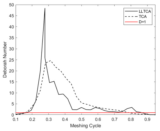
Figure 6.
Variation of Deborah number during a meshing cycle with input data predicted through LLTCA and TCA.
The results show that the Deborah number exceeds the value of unity for most of the meshing cycle, with parts of the meshing cycle being for the case of LLTCA. This strongly suggests that the lubricant film is subject to non-Newtonian shear throughout the meshing cycle [34,37]. Additionally, it is shown later that the film thickness values under the specified operating conditions yield Stribeck’s lubricant film ratios exceeding the limit for the onset of mixed regime of lubrication. Therefore, the effect of surface roughness is not considered in the current analysis.
2.4. Thermal Network Model
Aside from shear thinning due to non-Newtonian lubricant behavior, another salient feature of the high-performance spur gear transmission system is thermal shear heating and the conduction of heat through the solid boundaries. Therefore, it is essential to carry out a thermo-elastohydrodynamic analysis, which can be carried out analytically through the development of a thermal network model. The thermal network model is used to calculate the average temperature of the contact and the rise in surface temperature of the contacting solids (i.e., meshing teeth) from a cold start-up condition. The methodology is adopted from the original work of Morris et al. [39].
Rate of friction-induced heat generation, , is obtained as:
This heat is conducted away through the contacting surfaces of the meshing teeth pair with the rate of and , respectively. The remainder of the heat is carried away by the lubricant through convection, . However, it is shown that the convective heat removal rate, is almost negligible in EHL contacts due to the thinness of the lubricant film and its low flow rate [34,40,41]. However, convective heat transfer by the lubricant flow is retained here for the sake of completeness of the analysis. Thus, the thermal energy equilibrium dictates that:
Considering the inlet heating effect, the lubricant bulk flow temperature, , is calculated considering an initial solid body temperature of 40 °C, thus:
is obtained as:
where is the effective contact temperature and is the specific heat capacity of the lubricant, and its mass flow rate is found as [42]:
where , , and are the lubricant film thickness, viscosity, and density at the center of the contact, respectively.
A more accurate thermal EHL analysis would require consideration of two-phase flow, taking into account the effect of cavitation. However, this is beyond the scope of the current analysis. As Morris et al. [39] and Paouris et al. [40] have noted, the heat flowing to the bounding contacting surfaces would need to overcome several thermal resistive barriers, as illustrated in Figure 7. Therefore, an analytical approach based on a thermal network model is deemed to be suitable for the purpose of the current study.
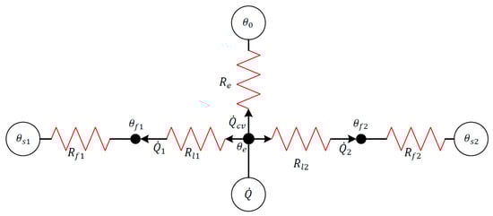
Figure 7.
The thermal network model [39].
From Figure 7, it can be deduced that
where and are the thermal resistances due to the lubricant film and the flash temperature rise of the solid surfaces. Resistances , , and can be obtained as follows:
In the current analysis, it is assumed that the generated heat takes place at the center of the contact. Therefore, the generated heat is conducted away through the lubricant layer adjacent to the contacting surfaces. The lubricant film thickness would be half that of the central film; thus, the corresponding thermal resistance becomes [40]:
The thermal resistance considering the flash temperature of solid surfaces is obtained as [41]:
As noted earlier, the effect of heat convected away from the contact due to the mass flow rate of the lubricant through the contact is usually neglected due to the thinness of an EHL film. Nevertheless, for the sake of completeness, the equivalent thermal resistance due to mass flow rate of lubricant is given as [39]:
The contact area is simply , where and are the Hertzian contact width and length, respectively. Moreover, is found as [42]:
Therefore, the heat conducted away through the gear blanks can be stated as
Thus, the heat balance Equation (23) takes the form:
The average (effective) contact temperature can now be determined as:
Once the effective temperature in the contact is determined, the temperature rise in the contacting solid surfaces and the lubricant exiting the contact can be determined using the heat partitioning method [39] illustrated in Figure 7. The thermal partition coefficient, for the bodies and lubricant can be found as:
and
Using Equations (35) and (36), surface temperature rise can be obtained as:
Note that it is assumed that the temperature calculated at each preceding meshing point neither influences the temperature of any subsequent meshing point nor the bulk gear temperature, as it is expected that a meshing cycle is completed prior to any rise in the bulk gear body being noted. This assumption is considered reasonable, since the Peclet number (the ratio of convective to conductive heat transfer) throughout the meshing cycle remains quite small (between 0.056 and 0.14). Furthermore, the study is concerned with the contact between a single gear teeth pair, taking place in a very short interval of time (a single engagement instant merely lasts s).
3. Method of Solution
The unknowns in the analysis are pressure, viscosity, density, localized contact deflection, lubricant film thickness, and temperature. The number of unknowns is equal to the number of equations at each instant of meshing. However, due to the non-linear nature of the relationships, it is necessary to use an iterative numerical technique to solve the thermo-EHL problem. The Effective Influence Newton–Raphson (EIN) method is used for discretization of Reynolds equation through a distributed line relaxation algorithm [43]. This technique is well-established for solving EHL contact problems, especially those subjected to high loads.
The following procedure is used:
- Inputs from LLTCA at the start of the meshing cycle are used.
- An initial guess is made for the film thickness at the center of the contact.
- The computational domain is set with an inlet length of and contact exit position of . The number of elements used in the direction of lubricant entrainment is 2051.
- Iterative pressure residuals are found using the under-relaxed Effective Influence Newton (EIN) method, including local surface deflection calculated through the use of Equation (9), which is based on Equation (38), where n denotes the iteration step and is the under-relaxation factor, typically –:
- The iterative procedure evaluates the contact pressure and continues until the pressure convergence criterion is satisfied:
- When pressure convergence is satisfied, the contact load-carrying capacity is calculated through the integration of pressure distribution over the computational domain as:
- The following equilibrium condition should be satisfied in order to achieve a load balance condition where is the applied load:
- If Equation (41) is not satisfied, the film thickness is updated through modification of the undeformed gap, using Equation (42):where is termed the damping (load relaxation) factor, and for the current analysis, the value of is used. Subsequently, the density and viscosity are updated using the newly found pressure. Then, Steps 4 to 8 are repeated until Step 7 is satisfied.
- Once the film thickness is determined, the thermal network model (highlighted in Section 2.4) is used to find the temperature of the lubricant as well as those of the adjacent meshing surfaces.
- Steps 2 to 9 are repeated for each point on the meshing cycle until the entire meshing cycle is completed.
4. Shear Stress and Friction
Friction is determined as:
where the shear stress, , for conventional Newtonian shear is given as:
However, as Paouris [29] noted, when the lubricant behaves in a non-Newtonian manner, then shear stress is given as:
Equation (45) is used when the Deborah number exceeds unity. Otherwise, shear stress is defined by Equation (44). This condition is deemed to occur as the calculated shear exceeds the Eyring shear stress of the lubricant, (i.e., ) [24,34,44,45]. Then, the shear stress becomes dependent on pressure and is found as:
where is the average contact pressure and is the limiting shear strength proportionality constant. The constant is found experimentally [45] and is usually in the range of 0.026–0.14, depending on the lubricant. In this investigation, .
5. Sub-Surface Stress Field
Fatigue spalling is a determining factor for the structural integrity of gearing systems. In a mixed regime of lubrication, the asperities on the opposing contacting surfaces can interact and cause surface wear and/or fatigue. However, in a pure EHL contact, which is the case assumed here, the root cause of fatigue emanates through sub-surface stresses reaching certain limits in the presence of sub-surface flaws. Therefore, it is important to predict the likelihood of onset of fatigue spalling in such cases. This is usually caused by the coupling of high generated contact pressures and shear [11,34,46]. In the absence of any surface coating, the approach adopted by Johnson [47] is commonly used to calculate the sub-surface stresses induced by pressure and shear under EHL conditions:
where is the intermediate parameter along the x-coordinate on the computational domain and is the Cartesian coordinate into the depth of the contacting solids. Viscous shear stress in the x-direction, , on the lower surface is obtained as:
It must be noted that a 2D sub-surface analysis approach should consider both shear stress in the direction of entrainment and pressure orthogonal to the surface; thus, the approach expounded here is quite suitable for the idealized 1D infinite line contact EHL. However, a more comprehensive approach would require a full 3D analysis, particularly for the case of finite line contacts. The computational domain for the sub-surface stress field is the same as that used for the evaluation of the generated pressures. The dimension into the depth of contacting solids uses a length of and 1000 elements are used along the z-axis. The sub-surface stress solver utilizes a trapezoidal numerical integrator.
For gears and bearings made of ductile material, failure is usually governed by cyclic reversing orthogonal shear stresses, , as shown by various authors [34,48,49,50].
6. Results and Discussion
The current investigation focuses on the high-performance transmissions of race vehicles. Therefore, the material and lubricant properties are chosen accordingly. An important point to note is that the surface topography is very smooth (of the order of 0.05–0.1 μm). Therefore, there is no need to consider boundary friction as well as surface fatigue, which would otherwise be required for the direct contact of rough surfaces in more conventional gearing systems. Table 1 lists the surface material and lubricant rheological data. The lubricant is considered to have similar shear thinning characteristics as those described by Paouris et al. [50]; thus, , and have been chosen accordingly and are included in Table 2.

Table 1.
Lubricant base properties [22].
Table 2.
Non-Newtonian lubricant properties [50].
Figure 8 shows a comparison of the predicted minimum film thickness during a meshing cycle, using the geometrical and kinematic data obtained through use of LLTCA and the conventional TCA. Despite the difference in the speed of lubricant entrainment and the contact radii of curvature, the lubricant film thickness remains almost unaltered between the two cases. However, at the start and the end of a meshing cycle, use of the TCA data appears to show a thicker film thickness value compared with that using the LLTCA data. The thinner film thickness predicted by the LLTCA case suggests that the inlet would move closer to the contact center, resulting in starvation during the early and later stages of the meshing cycle, which explains the reason for the insensitivity to lubricant entraining speed.
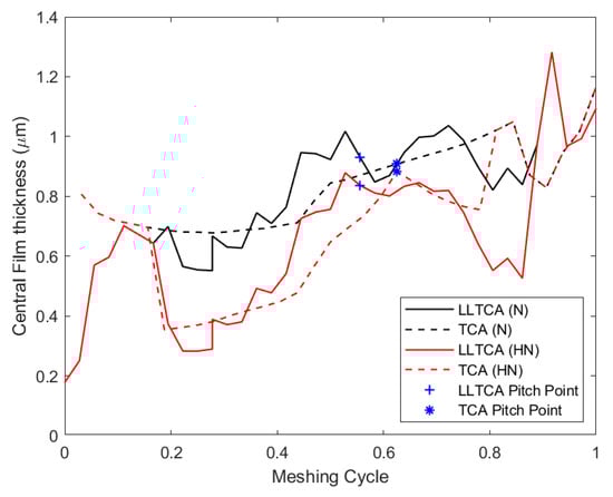
Figure 8.
Central contact thickness across the meshing cycle: N—Newtonian, HN—Havriliak, and Negami shear thinning.
The introduction of shear thinning originated from the non-Newtonian behavior of the lubricant has a significant effect on the lubricant film thickness. Figure 8 clearly illustrates the transition between Newtonian and non-Newtonian lubricant shear behavior with a sudden reduction in lubricant film thickness. Up to a 50% difference between Newtonian and non-Newtonian behavior for LLTCA and 48% for the case of TCA are noted. At the pitch point, there is no relative velocity between the contacting surfaces (i.e., pure rolling). With no sliding speed, the shear thinning effect is reduced, thus resulting in an increase in the thickness. However, even at low sliding speeds, the shear thinning effect has a significant influence on film thickness. With the LLTCA input conditions, at the pitch point, there is a reduction of 13%.
Figure 9 shows the change in pressure and film thickness between Newtonian and non-Newtonian behavior, including the effect of shear thinning. These results correspond to isothermal conditions at 40 °C. Clearly, the change in film thickness is the result of non-Newtonian shear thinning, reducing the lubricant film availability for entrainment into the contact. The pressure distribution remains unaltered as EHL films are insensitive to load, which primarily determines the generated pressures.
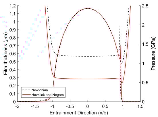
Figure 9.
Pressure and film thickness comparison between Newtonian and Havriliak and Negami Non-Newtonian behavior (LLTCA input).
As shown earlier, the contact appears more starved when taking shear thinning into account. This is shown by the reduced pressure spike at the contact exit for the non-Newtonian response, as well as the reduced film thickness.
It is noteworthy that since the gears considered in this study are for a high-performance application, the typical composite surface roughness values are well below 0.1 µm. For the LLTCA meshing cycle, including lubricant shear thinning, the Stribeck film ratio remains around 6.5. Thus, with the film thickness values encountered in this study, it is evident that the probability of asperity contact is negligible. Therefore, rough surface interactions are neglected in the current analysis.
Figure 10 shows the pressure distribution and the corresponding film thickness throughout a meshing cycle using the LLTCA input to the analysis with non-Newtonian shear taken into account under isothermal conditions. The equivalent Hertzian pressure distribution, which is applicable to dry elastostatic contact conditions, is also included on all the figures. This shows that the pressure distribution closely follows the Hertzian pressure profile except for the inlet hydrodynamic trail and the secondary pressure peak (i.e., the pressure spike or pip) in the vicinity of contact exit. As the inlet trail shrinks toward the edge of the Hertzian domain, contact starvation grows, leading to the diminution of the exit pressure spike. With increased loading and reduced contact kinematics as well as shear thinning, the exit pressure spike tends to the edge of Hertzian region with a reduced magnitude. In the extreme case of starvation, the pressure distribution tends to the Hertzian condition. This trend can be observed in the results of Figure 10, and it has been observed by many authors, including with experimental verification [51,52,53].
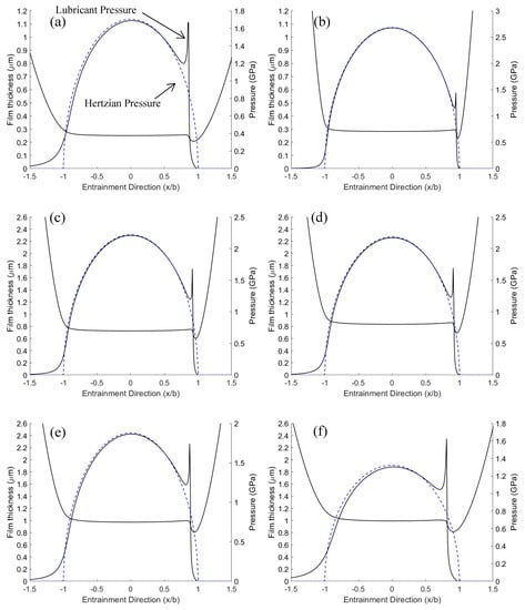
Figure 10.
Pressure and film thickness across the contact for mesh point (a) 0.056, (b) 0.25, (c) 0.472, (d) 0.666, (e) 0.917, and (f) 0.972 for the Havriliak and Negami cases.
For high-performance transmissions, it is important to be able to accurately predict the frictional power loss. Due to high lubricant shear strain rates in gear teeth meshing, the shear stress of the lubricant occurs mostly beyond the Eyring shear stress (i.e., non-Newtonian traction). Under these conditions, shear stress is no longer dependent on the lubricant film thickness, but it is dependent on the generated contact pressure. Hence, friction with input from both LLTCA and TCA are quite similar as shown in Figure 11. However, one should note that in practice, as the gear teeth go through numerous meshing cycles, the average temperature of the lubricant would rise as a result. In turn, this would reduce the local viscosity, resulting in an overall reduction in the generated viscous friction.
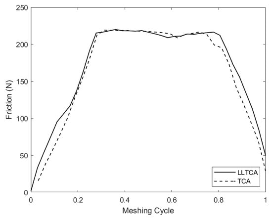
Figure 11.
Friction comparison between LLTCA and TCA for a complete meshing cycle.
Figure 12 illustrates the resulting generated contact temperature of the meshing surfaces throughout the meshing cycle with LLTCA input.
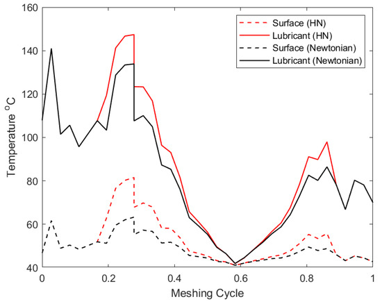
Figure 12.
Surface flash temperature of meshing bodies for Newtonian and non-Newtonian conditions for a complete meshing cycle.
Given the assumed initial low bulk lubricant temperature for this analysis, the predicted flash contact temperature is quite reasonable. The greatest contact temperatures occur in regions with highest Deborah number, which is associated with thinnest lubricant film under non-Newtonian traction. With reduced film thickness caused by cases of lubricant shear thinning, the flash temperature of solid surfaces increases accordingly.
Frictional power loss follows the same trend reported in the literature for gearing systems [18,22]. Figure 13 shows that for spur gears, the power loss diminishes at the pitch point, since there is a relative sliding of the meshing gear teeth pair (i.e., pure rolling contact). For both cases of LLTCA and TCA inputs, the power loss is quite similar from the start of meshing to the position of the pitch point. Thereafter, LLTCA input results in greater power loss prediction because of higher predicted sliding velocities. In fact, an increase of 22% is observed at some of the meshing points. Therefore, it is clear that for a more accurate evaluation of transmission efficiency, one should consider measured geometry as in the case of LLTCA. In particular, considering the number of meshing cycles in real applications, such relatively small differences can amount to a large deviation in the prediction of gear efficiency in the long term.
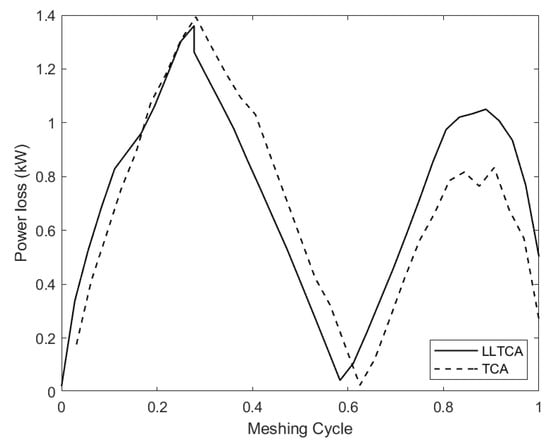
Figure 13.
Power loss throughout the meshing cycle.
For high-speed transmissions, which are based mostly on spur and bevel gear pairs, operational reliability is the paramount requirement, as their meshing teeth pairs are subjected to high pressures, shear, and generated temperature. Thin films can result in the direct contact of surfaces and wear. However, one of the main causes of failure is often sub-surface shear stresses of a cyclic nature, potentially causing fatigue spalling [11,49,52]. Figure 14 shows the axisymmetric nature of the orthogonal shearing stresses, at the beginning and the end of a meshing cycle. The pressure spike in the vicinity of contact exit induces a localized sub-surface field of its own, which is similar to the observations of Paouris et al. [50].
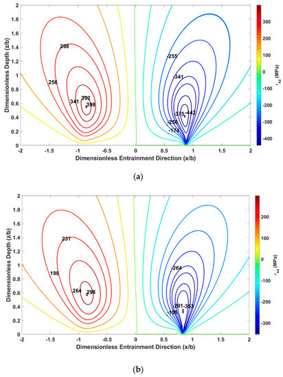
Figure 14.
Sub-surface orthogonal shear stress contours for meshing point (a) 1/18th, and (b) 35/36th position in the meshing cycle.
Sub-surface stresses are dependent on the generated contact pressure and friction. Since both LLTCA and TCA predict similar friction, henceforth, the analysis focuses on the difference between Newtonian and non-Newtonian LLTCA cases only.
The equivalent stress with the maximum alternating shear stress hypothesis, which is shown to be the closer representation of fatigue failures of bearings and gears [46,48], is given as:
where and are the alternating maximum and minimum shear stresses as in Figure 14a,b. As the equivalent stress approaches the yield of the material, failure due to fatigue spalling can occur in the presence of any sub-surface flaws such as pores or inclusions. Therefore, the larger the value of equivalent stress, the greater the chance of inelastic deformation due to sub-surface alternating shear stresses. Figure 15 shows that non-Newtonian shear yields higher orthogonal shear stresses.
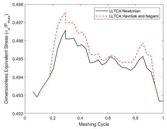
Figure 15.
Dimensionless equivalent stress along a complete meshing cycle.
Most gear meshing is subjected to the shear thinning of lubricant and non-Newtonian regime of traction under thermal EHL. Therefore, the prevalent sub-surface stress conditions are best represented by alternating shear stresses under non-Newtonian conditions.
7. Conclusions
The paper provides a comprehensive study of EHL of a meshing spur gear pair. Unlike previous studies reported in the open literature, the contact geometry and contact kinematics are obtained using both Loaded Lubricated Tooth Contact Analysis (LLTCA) instead of the traditional Tooth Contact Analysis (TCA). Therefore, more representative data are used in the subsequent EHL analysis of meshing teeth pairs. Furthermore, the effect of contact temperature rise, as well as the local non-Newtonian shear characteristics of the lubricant, affecting lubricant’s rheology, thus film thickness, friction, and power loss have been included in this study. This is more representative of real-life situations for high-performance transmissions, which have not hitherto been reported in the literature. It is shown that the shear thinning of the lubricant due to its non-Newtonian behavior significantly alters the predicted thermal conditions and power loss within the contact. Furthermore, high generated pressures and non-Newtonian traction lead to an increase in the sub-surface equivalent stress, based on the alternating reversing orthogonal shear stresses relative to the usually assumed Newtonian shear. This means that under representative conditions, thermo-EHL with non-Newtonian shear can lead to an increased chance of fatigue spalling throughout a typical meshing cycle. The paper also shows that predicted geometry and contact kinematics using traditional TCA may not be sufficient to accurately predict the friction and durability of spur gear pairs in high-performance applications. Furthermore, the study prompts future investigations into a detailed analysis of gear efficiency and overall performance, based on the LLTCA approach reported here.
Author Contributions
Conceptualization, G.S. and R.R.; methodology, R.R. and H.R.; software, G.S.; validation, G.S.; formal analysis, G.S., R.R., H.R.; investigation, G.S.; data curation, G.S.; writing—original draft preparation, G.S.; writing—review and editing, R.R. and H.R.; visualization, G.S.; supervision, R.R. and H.R.; project administration, H.R.. All authors have read and agreed to the published version of the manuscript.
Funding
The authors would like to express their gratitude for the financial support of the Engineering and Physical Sciences Research Council (EPSRC) extended to this research under the Centre for Doctoral Training for Embedded Intelligence (CDT-EI) and AVL List GmbH, grant reference: EP/L014998/1.
Conflicts of Interest
The authors declare no conflict of interest.
Nomenclature
| Area of contact | |
| Vogel viscosity constant | |
| Hertzian semi-half-width of the contact | |
| , | Vogel viscosity constants |
| Specific heat capacity of the lubricant | |
| Specific heat capacity of the solids body | |
| Deborah number | |
| Equivalent/reduced Young’s modulus of elasticity: | |
| Havriliak and Negami non-Newtonian function | |
| Friction | |
| , | Parameters for the Greenwood chart |
| Dimensionless materials’ parameter | |
| Dimensionless film thickness | |
| Film thickness | |
| Minimum film thickness for the undeformed (rigid) profile | |
| Central contact film thickness | |
| Nodal position identifier | |
| Thermal conductivity of the lubricant | |
| Thermal conductivity of the solids | |
| Contact length | |
| Lubricant mass flow rate | |
| Iteration counter | |
| Pressure | |
| Average contact pressure | |
| Maximum Hertzian elastic line contact pressure | |
| Rate of heat generation | |
| Heat conducted away through the bounding surfaces | |
| Heat convected away by the lubricant | |
| Shear field | |
| Radius of curvature of equivalent solid | |
| Conductive thermal resistivity of the lubricant | |
| Convective thermal resistivity of the lubricant | |
| Radius of curvature in the direction of entraining motion | |
| Radius of curvature in the side leakage direction | |
| Rolling velocity in the direction of lubricant entrainment | |
| Speed of entraining motion | |
| Relative sliding velocity | |
| Dimensionless (rolling) velocity parameter | |
| Velocity in the slide leakage direction | |
| Applied load | |
| Load carrying capacity of the lubricant | |
| Dimensionless load parameter | |
| Undeformed geometrical contact profile | |
| Cartesian coordinate set | |
| Bulk temperature | |
| Atmospheric reference temperature | |
| Time |
Greek Symbols
| Piezoviscosity coefficient at ambient temperature | |
| Piezoviscosity coefficient at specified temperature | |
| , | Havriliak and Negami parameters |
| Shear rate | |
| Localized elastic deflection | |
| Evans and Johnson’s friction parameter | |
| Viscosity at rest temperature and atmospheric pressure | |
| Dynamic viscosity of the lubricant | |
| Dynamic viscosity at the center of the contact | |
| Piezoviscosity of the lubricant (solely dependent on pressure) | |
| Bulk flow temperature | |
| Temperature rise | |
| Relaxation time | |
| Coefficient of friction | |
| Density of the lubricant | |
| Density at the center of the contact | |
| Density of the solid bodies | |
| Load relaxation parameter | |
| Equivalent stress | |
| Shear stress | |
| Limiting shear stress | |
| Characteristic shear stress | |
| Pressure relaxation parameter | |
| Thermal partitioning coefficient |
Abbreviations
| 1D | One-Dimensional |
| CMM | Coordinate Measuring Machine |
| EHL | Elastohydrodynamic Lubrication |
| EIN | Effective Influence Newton–Raphson |
| FEA | Finite Element Analysis |
| HN | Havriliak–Negami |
| LLTCA | Lubricated Loaded Tooth Contact Analysis |
| NVH | Noise, Vibration, and Harshness |
| TCA | Tooth Contact Analysis |
Appendix A
The gear parameters and assembly used for this investigation are shown below; further details are found in Oglieve et al. [19].
Table A1.
Gear pair specification [19].
Table A1.
Gear pair specification [19].
| Gear Type | Spur |
|---|---|
| Pinion No. Teeth | 13 |
| Wheel No. Teeth | 35 |
| Gear Module | 3.8 |
| Center Distance | 90 mm |
| Gear Width | 13.3 mm |

Figure A1.
Gear geometry assembly [19].
Figure A1.
Gear geometry assembly [19].

References
- Mohammadpour, M.; Theodossiades, S.; Rahnejat, H.; Kelly, P. Transmission efficiency and noise, vibration and harshness refinement of differential hypoid gear pairs. J. Multi-Body Dynamics 2014, 228, 19–33. [Google Scholar] [CrossRef]
- Wu, S.; Cheng, H.S. A Friction Model of Partial-EHL Contacts and its Application to Power Loss in Spur Gears. Tribol. Trans. 1991, 34, 398–407. [Google Scholar] [CrossRef]
- Diab, Y.; Ville, F.; Velex, P. Investigations on power losses in high-speed gears. J. Eng. Tribol. 2006, 220, 191–198. [Google Scholar] [CrossRef]
- Li, S.; Kahraman, A. Prediction of Spur Gear Mechanical Power Losses Using a Transient Elastohydrodynamic Lubrication Model. Tribol. Trans. 2010, 53, 554–563. [Google Scholar] [CrossRef]
- Petry-Johnson, T.T.; Kahraman, A.; Anderson, N.E.; Chase, D.R. An Experimental Investigation of Spur Gear Efficiency. J. Mech. Des. 2008, 130, 062601. [Google Scholar] [CrossRef]
- Li, S.; Kahraman, A. A tribo-dynamic model of a spur gear pair. J. Sound Vib. 2013, 332, 4963–4978. [Google Scholar] [CrossRef]
- Velex, P.; Maatar, M. A mathematical model for analyzing the influence of shape deviations and mounting errors on gear dynamic behaviour. J. Sound Vib. 1996, 191, 629–660. [Google Scholar] [CrossRef]
- Kahraman, A.; Blankenship, G.W. Effect of Involute Tip Relief on Dynamic Response of Spur Gear Pairs. J. Mech. Des. 1999, 121, 313–315. [Google Scholar] [CrossRef]
- Parker, R.; Vijayakar, S.; Imajo, T. Non-linear dynamic response of a spur gear pair: Modelling and experimental comparisons. J. Sound Vib. 2000, 237, 435–455. [Google Scholar] [CrossRef]
- Cooley, C.G.; Liu, C.; Dai, X.; Parker, R.G. Gear tooth mesh stiffness: A comparison of calculation approaches. Mech. Mach. Theory 2016, 105, 540–553. [Google Scholar] [CrossRef]
- Johns-Rahnejat, P.M.; Gohar, R. Point contact elastohydrodynamic pressure distribution and sub-surface stress field. In Int. Tri-Annual Conf. on Multi-Body Dynamics: Monitoring and Simulation Techniques; Bradford: Yorkshire, UK, 1997; pp. 161–177. [Google Scholar]
- Ding, Y.; Rieger, N.F. Spalling formation mechanism for gears. Wear 2003, 254, 1307–1317. [Google Scholar] [CrossRef]
- Tao, J.; Hughes, T.G.; Evans, H.P.; Snidle, R.W.; Hopkinson, N.A.; Talks, M.; Starbuck, J.M. Elastohydrodynamic Lubrication Analysis of Gear Tooth Surfaces from Micropitting Tests. J. Tribol. 2003, 125, 267–274. [Google Scholar] [CrossRef][Green Version]
- Moss, J.; Kahraman, A.; Wink, C. An Experimental Study of Influence of Lubrication Methods on Efficiency and Contact Fatigue Life of Spur Gears. J. Tribol. 2018, 140, 051103. [Google Scholar] [CrossRef]
- Litvin, F.L.; Fuentes, A. Gear Geometry and Applied Theory; Cambridge University Press (CUP): Cambridge, UK, 2004. [Google Scholar]
- Vijayakar, S.M. Tooth Contact Analysis Software: CALYX; Advanced Numerucal Solutions: Hilliard, OH, USA, 1998. [Google Scholar]
- Karagiannis, I.; Theodossiades, S.; Rahnejat, H. On the dynamics of lubricated hypoid gears. Mech. Mach. Theory 2012, 48, 94–120. [Google Scholar] [CrossRef]
- Fatourehchi, E.; Elisaus, V.; Mohammadpour, M.; Theodossiades, S.; Rahnejat, H. Efficiency and Durability Predictions of High Performance Racing Transmissions. SAE Int. J. Passeng. Cars Mech. Syst. 2016, 9, 1117–1124. [Google Scholar] [CrossRef]
- Oglieve, C.; Sivayogan, G.; Mohammadpour, M.; Rahnejat, H. Lubricated loaded tooth contact analysis for spur gear pair. Int. J. Powertrains 2019, 8, 23–39. [Google Scholar] [CrossRef]
- Radzevich, S.P.; Dudley, D.W. Handbook of Practical Gear Design; CRC Press: Boca Raton, FL, USA, 1994. [Google Scholar]
- And, P.S.; Velex, P.; Duverger, O.; Sainsot, P. Contribution of Gear Body to Tooth Deflections—A New Bidimensional Analytical Formula. J. Mech. Des. 2004, 126, 748–752. [Google Scholar]
- Elisaus, V.; Mohammadpour, M.; Theodossiades, S.; Rahnejat, H. Effect of teeth micro-geometrical form modification on contact kinematics and efficiency of high performance transmissions. J. Multi-body Dyn. 2017, 231, 538–555. [Google Scholar] [CrossRef]
- Litvin, F.L.; Fuentes, A.; Hayasaka, K. Design, manufacture, stress analysis, and experimental tests of low-noise high endurance spiral bevel gears. Mech. Mach. Theory 2006, 41, 83–118. [Google Scholar] [CrossRef]
- Evans, C.R.; Johnson, K.L. Regimes of Traction in Elastohydrodynamic Lubrication. J. Mech. Eng. Sci. 1986, 200, 313–324. [Google Scholar] [CrossRef]
- Chittenden, R.J.; Dowson, D.; Dunn, J.F.; Taylor, C.M. A theoretical analysis of the isothermal elastohydrodynamic lubrication of concentrated contacts. I. Direction of lubricant entrainment coincident with the major axis of the Hertzian contact ellipse. Proc. R. Soc. London Ser. A. Math. Phys. Sci. 1985, 397, 245–269. [Google Scholar]
- Olver, A.V. Gear lubrication—A review. J. Eng. Tribol. 2002, 216, 255–267. [Google Scholar] [CrossRef]
- Gohar, R. Elastohydrodynamics; World Scientific Pub Co Pte Lt: Singapore, Singapore, 2001. [Google Scholar]
- Hamrock, B.J.; Jacobson, B.O. Elastohydrodynamic Lubrication of Line Contacts. ASLE Trans. 1984, 27, 275–287. [Google Scholar] [CrossRef]
- Paouris, L.; Rahmani, R.; Theodossiades, S.; Rahnejat, H.; Hunt, G.; Barton, W. An Analytical Approach for Prediction of Elastohydrodynamic Friction with Inlet Shear Heating and Starvation. Tribol. Lett. 2016, 64, 10. [Google Scholar] [CrossRef]
- Havriliak, S.; Negami, S. A complex plane representation of dielectric and mechanical relaxation processes in some polymers. Polymer 1967, 8, 161–210. [Google Scholar] [CrossRef]
- Houpert, L. New Results of Traction Force Calculations in Elastohydrodynamic Contacts. J. Tribol. 1985, 107, 241–245. [Google Scholar] [CrossRef]
- Vogel, H. The temperature dependence law of the viscosity of fluids. Phys. Z. 1921, 22, 645–646. [Google Scholar]
- Crouch, R.F.; Cameron, A. Viscosity-temperature equations for lubricants. J. Inst. Pet 1961, 47, 307–313. [Google Scholar]
- Gohar, R.; Rahnejat, H. Fundamentals of Tribology; World Scientific Pub Co Pte Lt: Singapore, Singapore, 2008. [Google Scholar]
- Yang, P.; Cui, J.; Jin, Z.M.; Dowson, D. Transient elastohydrodynamic analysis of elliptical contacts. Part 2: Thermal and Newtonian lubricant solution. J. Eng. Tribol. 2005, 219, 187–200. [Google Scholar] [CrossRef]
- Greenwood, J.A. Presentation of Elastohydrodynamic Film-Thickness Results. J. Mech. Eng. Sci. 1969, 11, 128–132. [Google Scholar] [CrossRef]
- Reiner, M. The Deborah Number. Phys. Today 1964, 17, 62. [Google Scholar] [CrossRef]
- Bezot, P.; Hesse-Bezot, C.; Dalmaz, G.; Taravel, P.; Vergne, P.; Berthe, D. A study of traction in elastohydrodynamic lubrication: Experimental and simulated curves for a point contact lubricated by a silicone fluid. Wear 1988, 123, 13–31. [Google Scholar] [CrossRef]
- Morris, N.; Rahmani, R.; Rahnejat, H.; King, P.; Fitzsimons, B. Tribology of piston compression ring conjunction under transient thermal mixed regime of lubrication. Tribol. Int. 2013, 59, 248–258. [Google Scholar] [CrossRef]
- Paouris, L.; Rahmani, R.; Theodossiades, S.; Rahnejat, H.; Hunt, G.; Barton, W. Inefficiency predictions in a hypoid gear pair through tribodynamics analysis. Tribol. Int. 2018, 119, 631–644. [Google Scholar] [CrossRef]
- Olver, A.V.; Spikes, H.A. Prediction of traction in elastohydrodynamic lubrication. J. Eng. Tribol. 1998, 212, 321–332. [Google Scholar] [CrossRef]
- Sharif, K.J.; Evans, H.P.; Snidle, R.W.; Newall, J.P. Modeling of Film Thickness and Traction in a Variable Ratio Traction Drive Rig. J. Tribol. 2004, 126, 92–104. [Google Scholar] [CrossRef][Green Version]
- Jalali-Vahid, D.; Gohar, R.; Rahnejat, H.; Jin, Z.M. Prediction of oil-film thickness and shape in elliptical point contacts under combined rolling and sliding motion. J. Eng. Tribol. 2000, 214, 427–437. [Google Scholar] [CrossRef]
- Eyring, H. Viscosity, Plasticity, and Diffusion as Examples of Absolute Reaction Rates. J. Chem. Phys. 1936, 4, 283. [Google Scholar] [CrossRef]
- Hoglund, E.; Jacobson, B. Experimental Investigation of the Shear Strength of Lubricants Subjected to High Pressure and Temperature. J. Tribol. 1986, 108, 571–577. [Google Scholar] [CrossRef]
- Rahnejat, H.; Johns-Rahnejat, P.M. Mechanics of Contacting Surfaces. In Encyclopedia of Automotive Engineering; John Wiley and Sons: Hoboken, NJ, USA, 2014. [Google Scholar]
- Johnson, K.L. Contact Mechanics; Cambridge University Press (CUP): Cambridge, UK, 1985. [Google Scholar]
- Ioannides, E.; Harris, T.A. A New Fatigue Life Model for Rolling Bearings. J. Tribol. 1985, 107, 367–377. [Google Scholar] [CrossRef]
- Rahnejat, H.; Rahmani, R.; Mohammadpour, M.; Johns-Rahnejat, P.M. Tribology of power train systems. ASM Handb. 2017, 18, 916–934. [Google Scholar]
- Paouris, L.; Theodossiades, S.; De la Cruz, M.; Rahnejat, H.; Kidson, A.; Hunt, G.; Barton, W. Lubrication analysis and sub-surface stress field of an automotive differential hypoid gear pair under dynamic loading. J. Mech. Eng. Sci. 2016, 230, 1183–1197. [Google Scholar] [CrossRef]
- Hamilton, G.M.; Moore, S.L. Deformation and pressure in an elastohydrodynamic contact. Proc. R. Soc. London Ser. A. Math. Phys. Sci. 1971, 322, 313–330. [Google Scholar]
- Johns-Rahnejat, P.M. Pressure and Stress Distribution under Elastohydrodynamic Point Contacts. Ph.D. Thesis, Imperial College, University of London, London, UK, 1988. [Google Scholar]
- Jalali-Vahid, D.; Rahnejat, H.; Gohar, R.; Jin, Z.M. Comparison between experiments and numerical solutions for isothermal elastohydrodynamic point contacts. Appl. Phys. 1998, 31, 2725–2732. [Google Scholar] [CrossRef]


© 2020 by the authors. Licensee MDPI, Basel, Switzerland. This article is an open access article distributed under the terms and conditions of the Creative Commons Attribution (CC BY) license (http://creativecommons.org/licenses/by/4.0/).