1. Introduction
In the last twenty years, a so-called “contact splitting” has been a popular concept, stating that stronger adhesion can be achieved by dividing a contact surface into small sub-contacts [
1]. This concept was initially inspired by the observation of the biological adhesive pads of insects and geckos. This ability has been largely attributed to a micropad contact—often in the form of microfibrils [
2].
To mimic the property of the foot-hair structure of insects and geckos, a series of studies has been conducted from the fabrication of textured surfaces to investigation of the influence of size, number, shape and stiffness of pillars. It has been found that the strength of adhesion of a body with a fibrillar structure surface in contact with a smooth surface can be greater than two compact surfaces [
3,
4,
5]. In the experiment of [
6], more than double the adhesive force is observed in contact between micropillar-patterned polydimethylsiloxane (PMDS) surfaces and glass substrates compared with unpatterned surfaces, and this enhancement can be attained even for rough substrates. There are many theoretical works on the principle of contact splitting and contact mechanics perspectives on fibrillar structures, for example, a JKR (Johnson, Kendall and Roberts) -theory based solution of dividing the indenter into a large number of smaller pillars with a small cap radius [
2,
7] Contact surfaces below a critical size have been shown to develop a uniform stress distribution at maximum adhesion strength before a complete separation occurs [
8]. A detailed review can be found in [
2,
9,
10].
Very commonly, the pillars are modeled by linear springs, and the whole surface structure is represented by independent springs or a complicated hierarchical structure of springs with different stiffnesses to study the bio-inspired adhesive [
11,
12]. Brush structures have also been modeled by rigid micro-cylinders, based on Kendall’s theory of cylindrical contacts [
13]. Recently, adhesive contacts between a rigid brush structure and an elastic half space have been numerically simulated using the boundary element method (BEM) [
14,
15]. For a flat brush structure, it is found that the adhesive force is roughly proportional to the square root of the real contact area, meaning that adhesion is not enhanced [
14]. In the case of rough brushes where the height of pillars has an exponential probability density, similar qualitative results to Fuller and Tabor’s prediction [
16] were obtained, which states that the adhesive force is reduced with roughness [
15]. However, in these studies [
13,
14,
15], the pillars are rigid, which is not the case for insect or gecko feet. The flexibility may play an important role in adhesion and contact splitting.
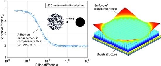
In this paper, we numerically study adhesive dry contact between a flat brush structure and an elastic half space taking account of the elastic deformation of pillars. The elastic deformability of pillars has been modeled by considering them as rigid cylinders coupled elastically to a rigid plate, as shown in
Figure 1, which can also be considered as a simplified model of a system with a thin elastic layer between pillars and a rigid plate which has an equivalent effect as independent springs [
17]. We restrict our analysis and simulations to the limiting case of very short ranged adhesive forces which we call Johnson, Kendall and Roberts (JKR) type, because the JKR theory uses exactly the same assumption. The adhesive contact between pillars and elastic half space is simulated by the fast Fourier transform-assisted BEM (FFT-assisted BEM) developed recently for the JKR-type adhesive contact [
18] and applied for various complicated contact problems [
19,
20]. Under the loading, the interaction between pillars and elastic half space must be coupled to the connection between the pillars and rigid plate.
This paper is organized as follows.
Section 2 gives theoretical analysis on current model in two limiting cases.
Section 3 presents the development of the BEM and coupling of spring flexibility and contact stiffness.
Section 4 gives numerical results, comparison and discussion. At last a short conclusion is presented in
Section 5.
2. Analytic Solutions for Limiting Cases
Under the normal load, the structure is pressed into an elastic half space by a macroscopic indentation depth
d that includes the deformation of both springs and half space. First, we consider a limiting case where the stiffness of springs is infinitely large. For adhesive contact between a flat rigid brush structure with nominal area
A0 and an elastic half space with elastic modulus
E and Poisson’s ration ν, the adhesive force (absolute value of minimal pull-off force) has been given in [
19].
where
is the work of adhesion per unit area,
is effective elastic modulus and
is a filling factor defined as the ratio of the real contact area
and the nominal area
,
(thus,
). This solution has the same form as Kendall’s solution to contact a single flat punch [
21], with an effective surface energy changed by the factor
. Rewriting Equation (1), by introducing the real contact area instead of nominal area, gives:
The term
in Equation (2) is Kendall’s solution to adhesive force for a compact cylindrical punch. Observing Equation (2), we conclude that if a compact flat cylinder is split into a sparse structure with a larger nominal area, then the adhesive force will be increased by a factor of
, as illustrated in
Figure 2.
Another limiting case corresponds to soft springs. If the contact stiffness of pillars is much larger than the stiffness of springs in the model, as illustrated in
Figure 1, the pillars will detach individually from the half space. We assume that the springs have the same stiffness and pillars have the same radius. Then the adhesive force for this flat brush structure is simply the sum of individual forces
where
N is the number of pillars and
a is the radius of pillars. Considering the same contact as shown in
Figure 2, we get
, and Equation (3) can be rewritten as:
From Equation (4), we conclude that in this limiting case, the adhesive force will be increased by the factor
. This result is quite similar to the theory of contact splitting where the spherical indenter is divided into pillars with a smaller cap radius, then an enhanced adhesive force is obtained by a factor of
based on the JKR theory [
7]. According to (4), the adhesive force seems to increase unlimitedly with an increase in pillar number. However, in any real system, the adhesive stress is final and determines the “theoretical strength” of adhesive contact. The strength cannot exceed this limit. From the point of view of the theory of adhesion, this limitation corresponds to the transition from the JKR type of adhesion to the DMT (Derjaguin, Muller and Toporov) kind.
Normalized by Kendall’s solution to the case of a compact cylindrical punch with radius
,
, the estimations (2) and (4) for the rigid and soft (spring) cases can be expressed as:
In the case of arbitrary stiffness of pillars, an analytical solution is not possible, and the contact has to be simulated with the BEM described in the next section.
3. Numerical Method
Adhesive contact between rigid indenters and an elastic half space has been numerically simulated by the BEM in the last two decades. The adhesion is usually modeled by the Lennard-Jones potential [
22,
23], or the simple Maugis–Dugdale stress–separation law [
24]. Recently a Griffith’s energy balance-based BEM has been developed for simulation of JKR-type adhesive contact [
18], which will be further developed for the flexible brush structures in this work.
The elastic contact between rigid pillars and elastic half space can be described by the classic solution of Boussinesq: the normal displacement of elastic half space
under the normal stress distribution
acting on position
is equal to:
For numerical calculation, it can be written in a discrete form
where
u is the displacement of surface element at position (
i,
j) in two-dimensional discretization,
is the normal stress acting on the element (
i’,
j’) and
is the influence coefficient and its value can be found in many works [
25]. Assume that the system has a dimension
N×
N, then the stress
and displacement
u have a dimension
N ×
N, but the matrix of the influence coefficient will have a dimension
N2 ×
N2. However, the convolution of integral (7) or (8) can be solved by the fast Fourier transform (FFT), which reduces the complexity greatly from
o(
N4) to
o(
N2log
N2). This technique has been applied by many researchers [
26]. Before carrying out the FFT, the matrix of the influence coefficient is usually constructed in the “convolution” form with the same dimension
N ×
N.
where “
” means convolution operation. The operation of FFT is then
As suggested by Liu et al. [
27], for the non-periodic contact in a finite domain, the matrix of pressure and influence coefficient should be expanded to dimension
2N × 2N, in which zero padding and wraparound order in this doubled domain must be performed to execute cyclic convolution. After the inverse FFT, the displacement
u is then extracted from the obtained displacement with the same doubled dimension.
Now we integrate the displacement of springs into this FFT-based BEM. Observing
Figure 3, it is clear that for the element in the contact region, the following relation is satisfied:
where index “
n” indicates the
n-th spring (or pillar),
u is the surface displacement of elastic half-space in this region
An, ∆
l is the displacement of the corresponding spring and
d is the general displacement of the brush structure. We assume the springs have the same stiffness
k. Then, the force on spring equals to the force on pillar
Substitution of (12) into (11) yields:
One can solve this contact problem numerically with the help of the existing BEM. However, the difficulty lies in the elastic interaction of pillars with each other. With the initially assumed displacement of pillars, the stress in the contact region can be calculated by the BEM, then stress as well as the force on each pillar will be obtained. By comparison of this contact force with the spring force, the displacement of pillars can be corrected. This iteration should then be repeated until all pillars are in equilibrium. However, this iteration cannot be realized if the number of pillars is large, because the correction of position for one pillar will induce the change of others. Due to the complicated interactions between the pillars, the iteration takes much time and the results are usually not accurate. We suggest another solution to this problem.
From Equation (12), the displacement of springs in a discrete form is:
where
h is the size of square elemental meshes. The operation of the sum in (14) can be written in the convolution form by introducing a new influence coefficient Π
where Π is called a discriminant matrix with an element of either one or zero and used to sum the stress in the contact region of the
n-th pillar. It is noted that we replace the sum operation by matrix convolution, since
σ is a matrix in discrete form. Thus, the deflection of the
n-th spring
corresponds to elements of the matrix on the right side of Equation (15). Let us discuss the size and element arrangement of squared matrix Π. For convenience, we denote
Lnξ and
Lnη as the greatest size of the
n-th pillar’s contact region in both directions, and
as the size of matrix Π. The nature of the convolution requires the following conditions:
(1) the length of Π must be larger than the doubled maximal value of
Lnξ and
Lnη,
and the element of Π should be one, as shown in
Figure 4.
(2) the size of matrix Π should be smaller than the minimal gap
gn among pillars.
For programming and operation of the FFT, the size of Π will be expanded in the same way as the matrix of influence coefficient
K and stress
, and additional elements are filled with zero. Then the relation (13) can be rewritten in convolution form as:
Similar to Equation (10), the operation of FFT can be carried out:
Therefore, one has only to add a term
to the matrix of the influence coefficient. In the simulation, we assume the displacement of the brush structure
is given (this means that we consider the displacement-controlled indentation). The stress
on the elastic half space can be obtained from Equation (10) by the conjugate gradient method as in the case of rigid indenters [
25]. A discussion of the convergence of this inverse problem can be found in [
25]. With this
, the displacement of elastic half space
as well as that of springs (position of pillars) can be determined by Equations (10) and (11). In this method, the influence of the spring is already integrated into the kernel matrix, therefore, it can dramatically reduce computation time and there is no further convergence problem.
In the above description, adhesion is not mentioned. In the studied model, adhesion occurs at the interface of pillars and elastic half space, thus the algorithm of adhesive BEM for rigid indenters suggested in [
18] is still valid for the current case. In [
18], Griffith’s crack criterion is used to analyze the detachment of the element, i.e., the elastic energy stored in the elements will be released to accomplish the needed adhesion work to create new surfaces. Based on that, a stress criterion is proposed to determine the detachment of contacting elements. As for the computation procedure, it is simple for the flat brush structure. In the simulation of displacement-controlled pull-off, we initially keep the contact area constant equal to the total surface area of pillars when an incremental displacement is given. Then the stress distribution can be obtained according to Equation (19). By comparing this tensile stress with the critical value of stress, the detachment of elements can be determined, and a new contact area is generated. With this new contact area, the above iteration is repeated until both pressure and geometry conditions for all elements in the contact area are met. The details on the principle and numerical procedure can be found in [
18].
4. Results and Discussion
With the method described above, we carry out the numerical simulation and investigate the influence of stiffness and numbers of pillars. The pillars have the same radius and are regularly or randomly distributed in a square area
L ×
L. The system is discretized with 512 × 512 points. The filling factor is almost constant for all cases,
. The stiffness of springs
k, and number of pillars
N will vary. The following normalizations are used in the whole analysis: forces and indentation depth are normalized by Kendall’s solution for a cylindrical punch with the same real contact area
A:
The spring stiffness is normalized as follows:
Here,
E*L is roughly the contact stiffness of the macro-brush structure with elastic half space.
Figure 5 shows the simulation examples of the pull-off process of a brush structure with 16×16 pillars. The dependence of the normal force
on the macroscopic displacement of the structure,
, is shown for three values of stiffness
. For a large amount of stiffness,
, the
F-
d curve and the detachment process are similar to that for the rigid pillars, as described in [
14,
19] (
Figure 5a). Separation initially occurs at the sharp corners of the contact zone and it propagates inwards in a circle-like shape, then all pillars detach completely at once. The maximal pull-off force, which is identified as adhesive force,
, is about 1.8, which indicates that the adhesive force is 1.8 times larger than in the case of a compact cylindrical punch with the same
real contact area. This value is very close to the limiting case of rigid pillars,
, according to Equation (5).
When the pillars become soft (small spring stiffness), e.g.,
as shown in
Figure 5b, the complete detachment occurs when the contact area is still not a circle-like shape. In the case of very little stiffness
(
Figure 5c), the normal force always increases linearly until the moment when all the pillars detach instantly.
Dependences of adhesive force
on the stiffness
for different numbers of pillars are shown in
Figure 6.
Figure 6a shows the case of regularly distributed pillars with numbers of 8 × 8 (64), 16 × 16 (256), 24 × 24 (576) and 48 × 48 (2304), and
Figure 6b shows the case of random distribution with 64, 220, 425 and 1620 pillars. With a large amount of stiffness (in the range of
), the adhesive forces for both cases and numbers of pillars are almost the same, and slightly larger than the value of theoretical approximation from Equation (5) (solid lines in the bottom right of figures), which is similar to the rigid case reported in [
14]. Decreasing the stiffness leads to an increasing adhesive force until it reaches a plateau. For soft pillars, the pillar number plays an important role in the adhesive force. The value of
indicates the adhesive force for a flat compact punch with the same area of cross section. Therefore, one can see that the adhesive force is strongly enhanced if the punch is split into fibers, especially when the fibers are soft. For example, the adhesive force increases by a factor of six for 2304 pillars. It is also seen that for a larger number of pillars, the stiffness needed to reach the plateau of the soft region is smaller. For example, for 64 pillars, it is
, but
for pillar number 2304.
Focusing on the plateau region with very little stiffness in
Figure 6, we compare the adhesive force in this region with the theoretical prediction
, Equation (6). The curves are presented in a double logarithmic plot in
Figure 7. The numerical results have the same power law with a power of 1/4 as the theoretical prediction, but the amplitude coefficient is about 1.2 to 1.3 times smaller than in the analytical estimation.
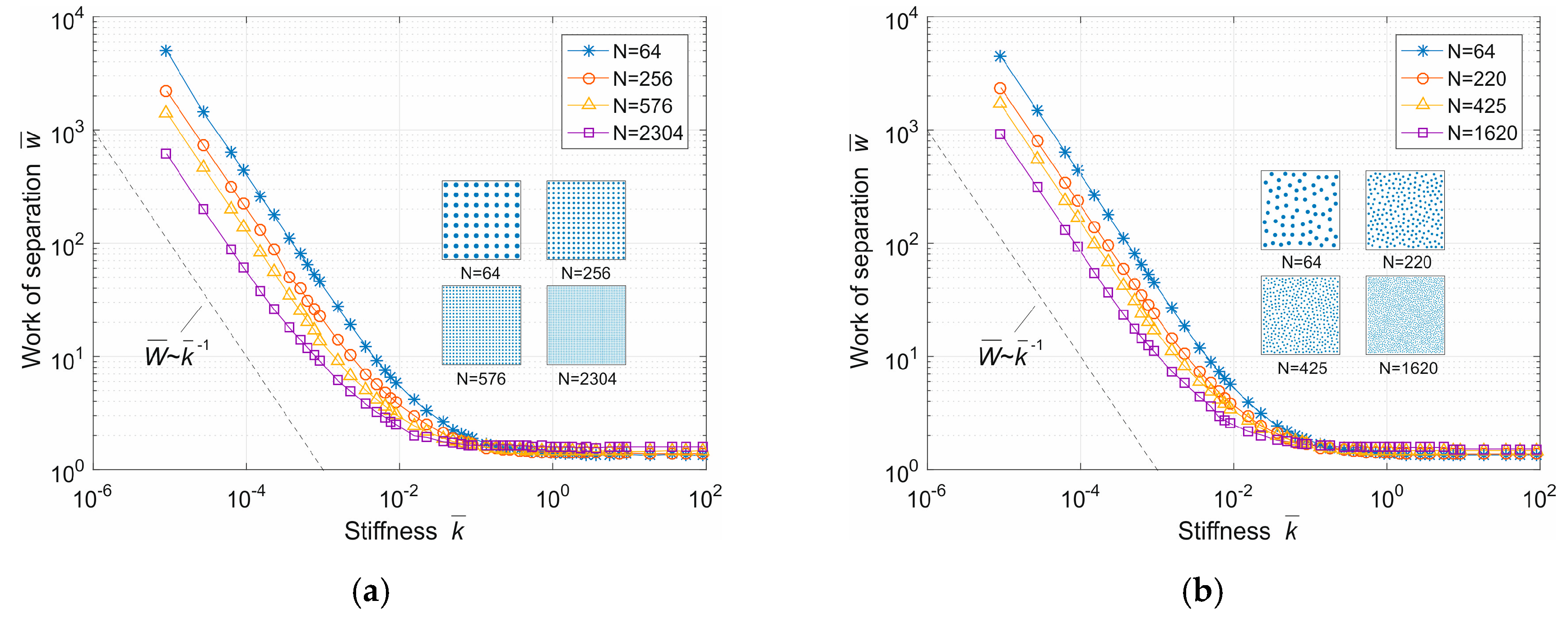
We discuss the work of separation briefly, which is simply obtained from the
d-F curve from zero indentation to complete separation. It is known that in the case of a rigid cylindrical punch with radius
a0, the work of separation is equal to [
19]:
Half of this energy will be used to create two new surfaces and the other half will dissipate in the elastic foundation. In the following discussion, the work of separation is normalized by the value of (23).
In
Figure 8, the adhesion work for separation for different stiffnesses and pillar numbers is presented. It can be found that for a large amount of stiffness, the adhesion work is roughly equal to the case of a rigid compact punch. With the reduction of stiffness, the adhesion work increases, since the energy stored in springs becomes important. Furthermore, the work of separation decreases with the number
N.
If the pillars are very soft, the energy will be stored mainly in the springs. The force on each spring in this case can be calculated from Equation (3)
Thus, the elastic energy stored in all springs with stiffness
k is roughly
In dimensionless form it can be written as:
Following Equation (27), the work of separation
is inversely proportional to the stiffness
, and decreases with the number of pillars
N. This approximation coincides with the result for very little stiffness, as shown in
Figure 8.


