Friction and wear processes are directly connected with each other within tribological systems. The following section deals with the elucidation of damage processes occurring in journal bearing systems by using the test methodologies herein proposed.
3.2.1. Evaluation of Wear Processes
Generally, both systems are superbly capable of evaluating wear processes going on in journal bearing systems.
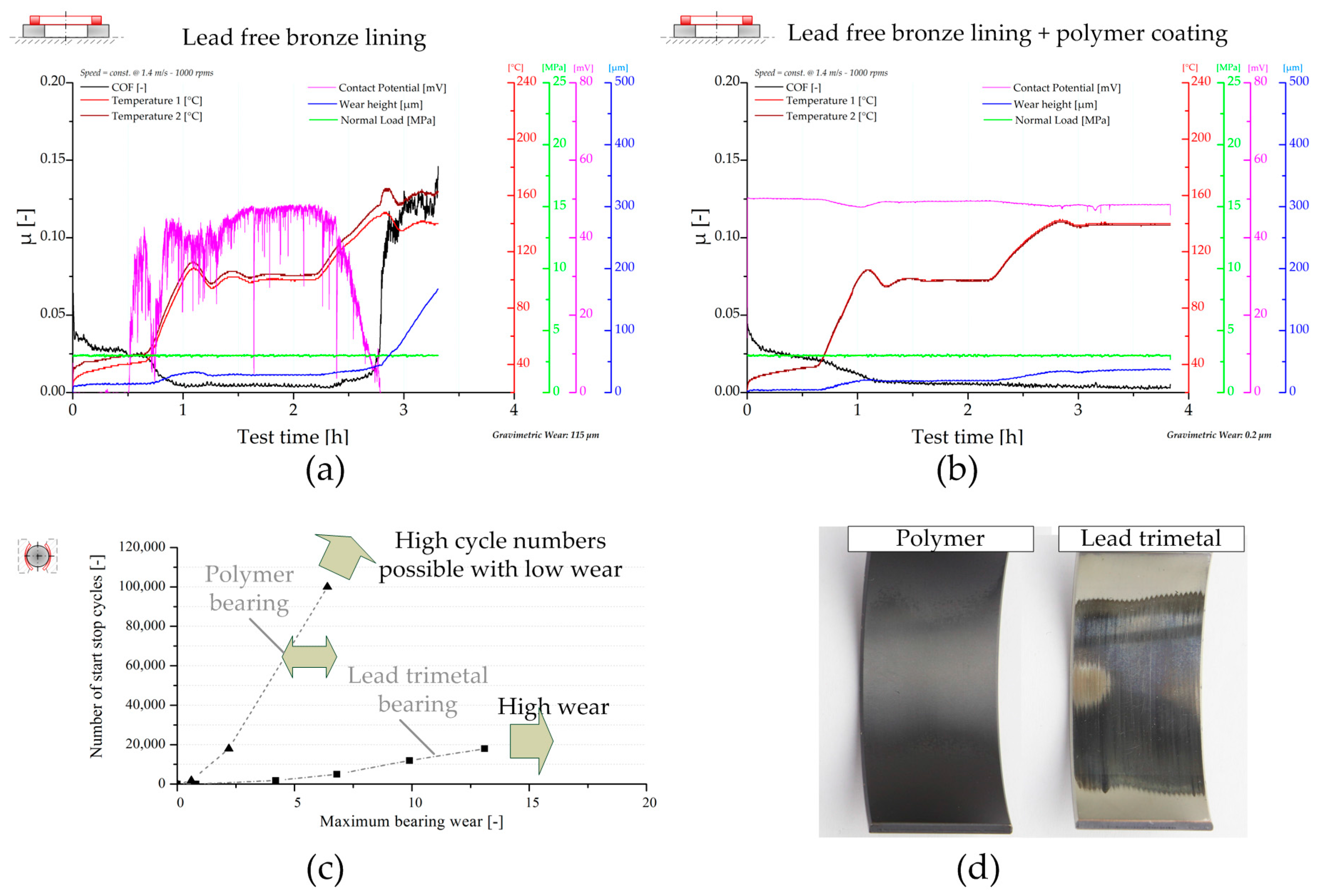
Figure 6a,b show the material effect regarding wear resistance and failure tolerance during mixed friction sliding. The test data have been determined with the RoD set up in a temperature test procedure (load and speed are constant as shown). In
Figure 6a a system using a lead free bronze lining is depicted. The plot shows a running in process at room temperature (RT) and during the initial heating step indicated by the drop of µ. At elevated temperatures of 100 °C, stable sliding conditions with low µ, high CP, which indicates the formation of boundary layers and protective interface processes and no wear evolution during this period, takes place (the reader may note that during the heating period the wear graph is influenced by the temperature changes). However, during the heating step to 140 °C, the vulnerable system behavior is emphasized. Shortly after starting the second heating period, the minor changes of temperature result in the start of wear processes. The CP signal drops at first, followed by a minor increase of µ as well as a slight raise in the wear graph. When the CP reaches its minimum, severe wear processes start, indicated by high wear rates, high µ, and an increase of friction heat. In contrast, the similar system using a lead free bronze lining but coated with a polymer overlay is shown in
Figure 6b. During the whole test procedure, no significant wear events take place. This is documented by the various measured parameters and verified by gravimetric wear measurement. The relative wear height is influenced by the heating situation, which changes the capacitive signal. Therefore, a wear graph, which only follows the temperature level, indicates that no significant wear processes take place. Furthermore, it can be seen that no significant friction heat is recorded, the CP signal is high during the whole test, and µ is constant and low after running in. A further example of the visualization capability of sliding and wear processes of the RoD set up is documented by the authors in [
20], focusing on the functionality of AlSi sliding material.
Furthermore, wear processes induced by start stop motion can be replicated by the herein presented test configurations. In
Figure 6c, the wear evolution during start stop conditions (1.64 MPa, 120 °C oil bath temperature, 0–1.25 m/s in 5 s) obtained with the bearing segment set up is given. In this regard, two different materials are shown. In the case of the lead trimetal bearing, a pronounced wear evolution after short number of cycles (below 20,000) settles. In contrast, it can be highlighted that using an advanced polymer coating instead of the lead coating improves the start stop wear resistance crucially. The differences emphasized by the test data are confirmed by surface analysis shown in
Figure 6c. In this depiction, the conditions of two bearing shells with lead and polymer coating are compared with each other after a similar number of start stop cycles. The wear track of the lead coating is clearly visible, whereas the polymer coating appears close to new conditions. Also elsewhere, the superiority of polymer overlays concerning start stop wear resistance is documented [
21], which proves the validity of the results herein presented. A detailed study by the authors concerning start stop wear of bearing systems using the herein applied bearing segment system is published in [
22].
Furthermore, the tribo-chemical wear processes can be resolved.
Figure 7 depicts the effect of corrosive wear on lead free bronze bearing material as well as the prevention thereof by using specific corrosion inhibitors (CIs). In the case of Oil C, a corrosion layer containing S and Zn forms on the bronze material, see
Figure 7a. This effect is also visible by the naked eye as emphasized in
Figure 7b. These processes affect sliding and wear conditions, highlighted in
Figure 7c showing a temperature step test procedure with constant speed at 1.4 m/s and 3 MPa loading. The friction curve of the system using Oil C rises at elevated temperature, thus indicating adhesive processes. In contrast, optimized lubricant design with corrosion inhibiting components (Oil D) results in prevention of this layer formation, see
Figure 7b. The resulting wear performance indicates a stable sliding condition paired with low friction losses.
The conclusions and knowledge acquired with testing find their application in the improvement and development of products as well as in the numerical life time analysis and product design. The cornerstone of numerical wear assessment was laid by Archard and Hirst [
23]. The authors proposed the model according to Equation (1), which correlates properties of the mating surfaces of journal bearing and shaft with the external load
P:
In this equation,
W is the worn volume,
s the sliding distance,
pm the flow pressure of the softer material, and
K a material-related empirical constant describing the probability of the formation of a wear particle. The transformation of Equation (1) into an ordinary differential equation, see Equation (2), provides the mathematical base for the numerical wear evaluation, where
w is the wear height,
p the asperity contact pressure,
v the sliding speed, and
C is an empirically determined parameter that describes the relation between wear volume and the introduced frictional energy during sliding solid contact [
24]. The steps behind this transformation include the division of Equation (1) by the nominal contact area and the derivative with respect to time. Consequently, the normal load
P transforms to a pressure which is correlated to the asperity contact pressure to evaluate solely the effects resulting from asperity interactions. The time derivative transforms
s into
v while
C unites the material intrinsic parameters
K/
pm.
In recent years, numerical tools have been developed at the Chair of Mechanical Engineering which allow the investigations of conforming and non-conforming contacts in regard to friction and wear phenomena. The tribological simulations of (thermo-)elastohydrodynamic contacts, for e.g., gear tooth contact and journal bearing, are conducted with COMSOL Multiphysics. By considering Equation (2), wear and its effect on the lubrication gap’s geometry can be modelled fully, coupled with the equations describing the physics of (T)EHL. For presentation purposes, a numerical scenario derived from conducted tests on the BS was chosen. The model of the core parts of BS is depicted in
Figure 8. In accordance with the real test setting, the force is applied on boundary A while the Reynolds equation, the equation representing asperity contact pressure according to Greenwood and Williamson [
25], as well as Equation (2) are solved on boundary B, allowing for the resolution of friction and wear processes. The contact behavior represented by an analytical function calculated based on the theory by Greenwood and Williamson is considered unaffected by roughness changes due to wear for the entire numerical scenario. The effect of wear is considered in the change of the lubrication gap’s geometry. In interplay with the initial lubrication gap height
h0 and the structural deformation
u, the wear height determines the lubrication gap’s height. C, D, and E represent the boundaries to the surrounding structure. The guiding function of the surrounding structure is considered by the application of roller conditions, which restrict deformation in the boundary’s normal direction.
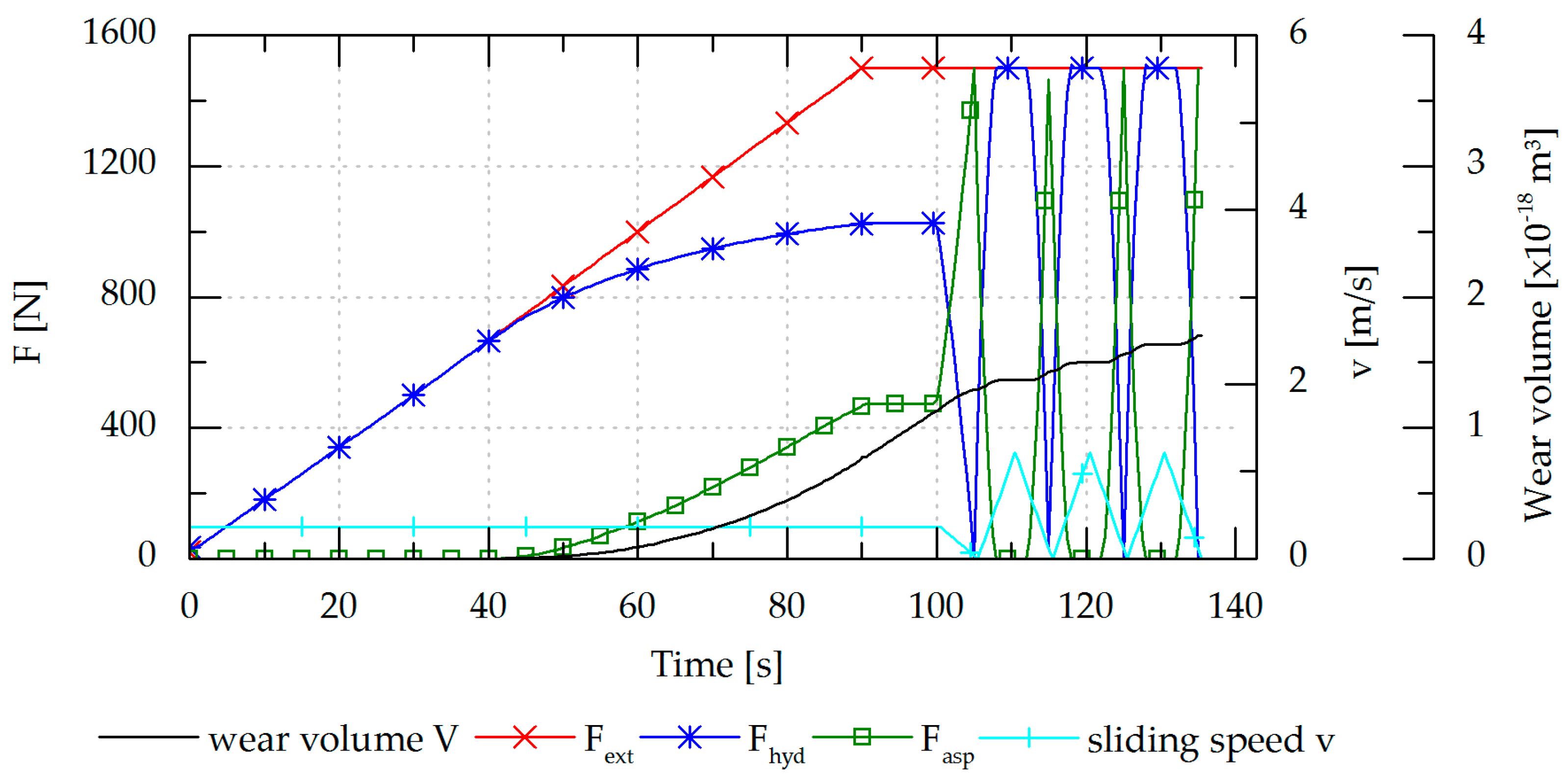
A representative numerical scenario based on conducted tests is depicted in
Figure 9. A value of 1.4 × 10
−13 [m
3/Nm] is chosen for C. The thermal conditions are considered to be constant. For the quantitative comparison with conducted tribological tests, the numerical frameworks allows for the implementation of temperature dependent oil parameters. In the initial state, the system operates in the fluid lubrication regime under a low external load of
Fext = 1500 N, a unit load of 1.65 MPa, and a sliding speed
v of 0.37 m/s, which is kept constant until
t = 100 s.
Fext is totally carried by the force resulting from the hydrodynamic pressure
Fhyd. By increasing
Fext the system is steadily pushed towards harsher loading conditions. The system counteracts the increasing load by decreasing the fluid film thickness, which results in an increased hydrodynamic load carrying capacity. However, when the fluid film thickness drops within the range of surface roughness, asperities start to interact, resulting in a rising
Fasp. At 40 s, the system turns into the mixed lubrication regime indicated by the onset of the asperity contact force
Fasp. Simultaneously, the wear volume starts to rise and depicts an exponential run until the time of 100 s at which start stop cycles begin. During the times of low speeds, the hydrodynamic load carrying capacity is insufficient. Consequently,
Fasp contributes to help carry the external load. Within this period of time, wear due to solid contact occurs and a rise of the wear volume can be observed. During the phases of sufficient hydrodynamic load carrying capacity due to a sufficiently high sliding speed, the total load is carried solely hydrodynamically while asperity contact is absent and the cumulative measure of the wear volume remains constant.
Hence, the developed numerical methodology in COMSOL Multiphysics represents a significant and effective tool for the assessment of wear due to solid contact in tribological contacts. A promising tool for the evaluation of wear was developed whereupon the incorporation of suitable test data and the comparison between numerical and test results is the subject of current investigations.
3.2.2. Seizure Performance Screening
This section elucidates the capability of the presented test methodologies to visualize emergency running properties of journal bearing systems and demonstrates the potentialities of the obtained experimental results contributing to the optimization of bearing systems concerning this aspect. In principle, emergency properties and seizure performances are tested according to standard test procedures by means of load tests by increasing the normal loading either linearly or in a step wise manner [
26]. Hence, the systems are dragged into severe sliding conditions, such as may occur during application operation, and the ability to withstand this stressing is detected.
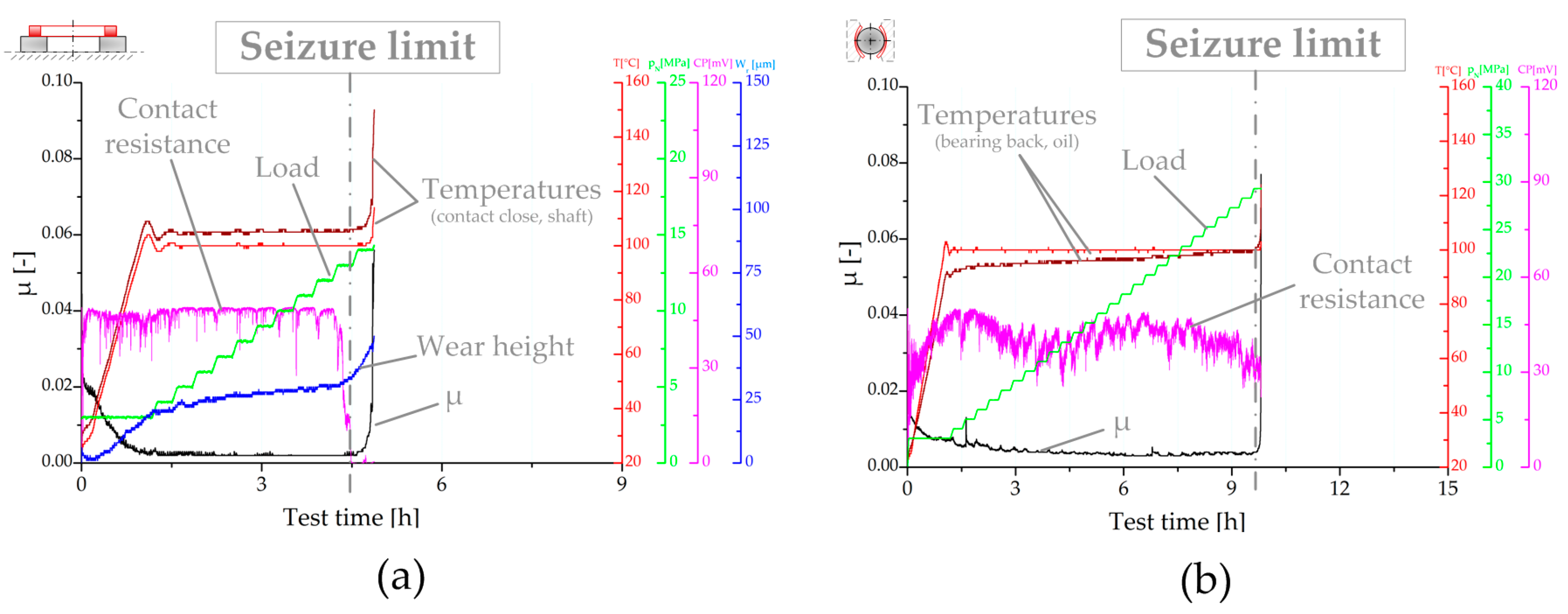
Figure 10 demonstrates the experimental resolution of tribological processes during emergency running conditions of the ring-on-disc set up (
Figure 10a) and the bearing segment system (
Figure 10b). For the given examples, a characteristic trimaterial bearing, composed of a steel back, a lead bronze lining, a Ni barrier, and an AlSn sputtered coating, has been tested in combination with 34CrNiMo6 shaft material and fully formulated heavy duty diesel engine oil.
For both systems, upon the start of sliding at room temperature, the coefficient of friction starts to decrease. The decrease of the COF can be attributed to running-in of the mating surfaces and the decrease of the viscosity due to heating. The contact resistance raises immediately at the beginning in both cases. At the RoD set up, the CP signal stabilizes for the given mixed friction regime due to formation of isolating oxide and boundary layers. In the case of the bearing segment system, hydrodynamic and solid contact situations vie for domination and, subsequently, the CP signal shows a more hectic behavior (the reader may note that testing seizure performance in the case of the bearing segment system requires bearing shells with a smaller area of contact, and owing to this aspect and the assembly of the test configuration, the base voltage drop is higher compared with RoD). At the beginning of the seizure tests, the temperature is heated up to a 100 °C steel specimen temperature for RoD and oil bath temperature for the bearing segment set up. Further heat development can be attributed to friction heat. As the further courses of the test plots demonstrate, both set ups are able to highly resolve the subsequent tribological processes including the scuffing process of the two friction partners. In the case of RoD, µ stays low and constant during the load stages up to 13 MPa. This can be traced back to the good sliding properties of the Al based coating. A deeper insight into the tribological processes going on is provided by the wear and CP signal. First it has to be noted that the initial increase of the response of the capacitive wear sensor is based on the external heating, which affects this measurement principle. However, thereafter, under almost constant temperature conditions, a slight and constant raise of the wear graph is seen, thus indicating minor wear events, apparently assigned to the bearing overlay. The CP signal drops ex-ante hinting at imminent failure events. Shortly after, the wear rate increases. At this point, µ as well as the system temperatures are still low. Hence, a catastrophic failure has not yet occurred. However, afterwards, scuffing takes place, thus raising µ and the corresponding friction heat, which requires a stop of the movement and the test. Similar resolution of severe failure processes of bearings is provided by the bearing segment system. In contrast to the RoD test, small spikes of µ are detected during stable sliding conditions. These events exhibit the system properties when dragged from hydrodynamic conditions to severe boundary sliding conditions. In the case of the hard sputter overlay, many small spikes are noted. Similar to the RoD set up, the evolution of CP, which slightly decreases several load steps before the scuffing, indicates the upcoming of failure events. The higher energy input of the set up results in more heat development, noted by the rise of the bearing back temperature, as well as the more rapid scuffing processes, which result in an overlap of CP drop and µ/temperature increase.
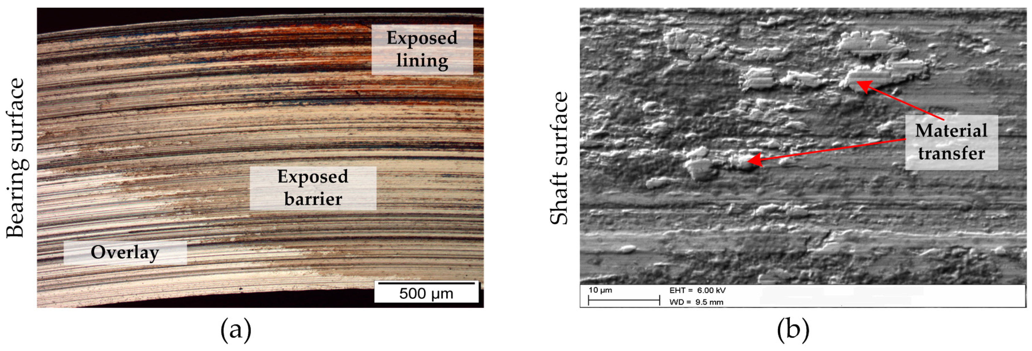
Figure 11 depicts bearing and shaft surface conditions after seizure tests showing scuffed conditions. This verifies the previously observed processes going on by the measurement quantities. The emergency capacity of the bearing overlay and the protecting anti-wear additives of the lubricant are overloaded upon reaching the seizure load limit. This means that soft phases of the overlay are consumed, and sacrificial anti-wear layers of the lubricants are removed and fail to reform with the same speed. The overlay wears off and the substrates are exposed, see
Figure 11a. The substrates provide higher affinity towards the steel counterpart compared to that of the top bearing overlay. Subsequently, scuffing processes take place. These scuffing events result in galling marks on the exposed substrate areas and material transfer on the steel shaft material, see
Figure 11b.
The precise detection of tribological processes and high reproducibility of the test set ups can be used for high quality screening with low scatter of various journal bearing systems.
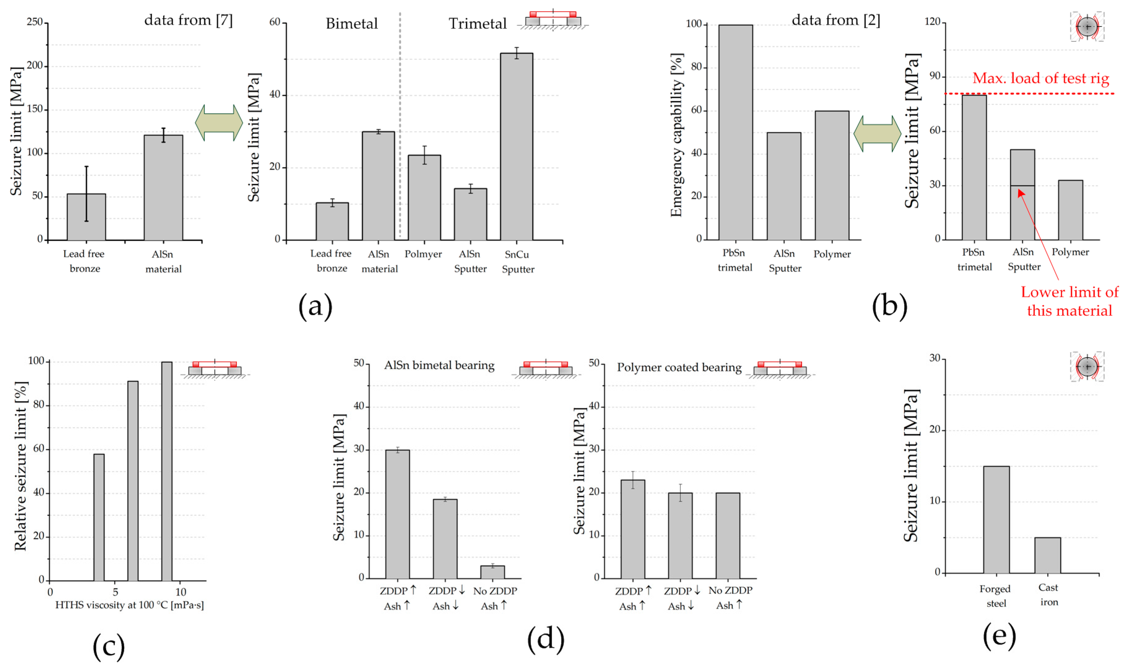
Figure 12 shows seizure performance and emergency running properties of various journal bearing systems depending on bearing material, shaft material, and lubricant; therefore, it outlines the possibilities for specific studies in this area of interest by using the herein presented test methodologies (the data have been determined in seizure load step test procedures as shown in
Figure 10a,b).
Figure 12a depicts the ranking of several bearing materials, lining materials, and coatings to withstand seizure up to critical load values and verifies the obtained results by comparison with literature ranking of bearing rigs. As for the lining materials, it can be highlighted that, unsurprisingly, AlSn materials possess higher emergency capability compared to that of harder lead free bronze material, which matches relatively results known from the literature. In the case of tribological coatings, usually applied on lining materials with insufficient tribological properties, the tested polymer overlay results in good performance with the RoD set up. Furthermore, superior performance can be achieved with a novel Sn based sputter coating, which is the result of a comprehensive optimization process to design a bearing material with enhanced emergency properties and sufficient hydrodynamic load bearing capacity.
With the aid of the bearing segment system, reliable results are obtained. This is also verified by comparison with rankings from literature (
Figure 12b). Highest seizure load resistance, which means emergency running capability, is reached by using a lead based electroplated bearing. Bearing products using Al based sputter coatings or polymer overlays provide lower seizure load limits relative to the tested electroplated coating.
With the applied methodologies providing low measurement scatter, the effect of lubricant formulation (viscosity and additive formulation) on the emergency running performance of bearing systems can be visualized. As seen, the robustness of various bearing systems tested is significantly decreased using lower oil viscosities, shown in
Figure 12c. Regarding additive formulation, for e.g., the decrease of Zincdialkyldithiophosphate (ZDDP) content affects the performance of AlSn bearing material negatively, whereas an optimized polymer coating is less sensitive to the decrease of protective lubricant additive amounts, see
Figure 12d.
In addition, the influence of the shaft counterpart design (material/surface structures) can be investigated using the given test methodologies. In
Figure 12e, a comparison of the performance of systems using a forged steel counterpart and systems using a cast iron counterpart is depicted. It can be seen that the forged steel shaft provides higher seizure resistance. The differences can be traced back to abrasion damages, induced by metal flaps with burrs around the graphite inclusions in the case of cast iron. However, by means of optimized surface treatment of the cast iron material, this negative effect can be eliminated. Further details can be found in a corresponding in-depth study by the authors published in [
27].
