Article

Effect of Laser-Textured Groove Patterns on Friction Reduction and Stress Distribution in High-Speed Steel Surfaces

by
Viboon Saetang
1,2,
Ponthep Vengsungnle
3,
Hao Zhu
4,
Huan Qi
2,5,
Haruetai Maskong
6 and
Witthaya Daodon
6,*
1
Department of Production Engineering, Faculty of Engineering, King Mongkut’s University of Technology Thonburi, Bangkok 10140, Thailand
2
Zhejiang-Thailand International Joint Laboratory on New Materials Digital Design and Processing Technology, Hangzhou City University, Hangzhou 310015, China
3
Department of Agricultural Machinery Engineering, Faculty of Engineering and Technology, Rajamangala University of Technology Isan, Nakhonratchasima 30000, Thailand
4
School of Mechanical Engineering, Jiangsu University, Zhenjiang 212013, China
5
College of Engineering, Hangzhou City University, Hangzhou 310015, China
6
Department of Industrial Engineering, Faculty of Engineering and Technology, Rajamangala University of Technology Isan, Nakhon Ratchasima 30000, Thailand
*
Author to whom correspondence should be addressed.
Lubricants 2025, 13(9), 419; https://doi.org/10.3390/lubricants13090419
Submission received: 20 August 2025 / Revised: 15 September 2025 / Accepted: 17 September 2025 / Published: 18 September 2025

Abstract

Excessive surface friction encountered during metal-forming processes typically leads to die wear and seizure in part surfaces, which consequently shortens the die’s service lifespan and lowers the surface quality of the formed parts. To minimize surface friction, tool surface modification is required. This study focuses on reducing the sliding friction of SKH51 high-speed steel by fabricating micro-grooves with various crosshatch angles using a nanosecond pulse laser. The effects of laser texturing parameters on achieving the groove aspect ratio of 0.1 were investigated. This aspect ratio facilitates lubricant retention and enhances lubrication performance on the contact surfaces. The influence of groove crosshatch angles (30°, 60°, and 90°) on the friction in the sliding contact between a textured high-speed steel disc and an AISI304 stainless steel pin was evaluated using a pin-on-disc test with a constant load. Moreover, the contact pressure distribution and stress concentration associated with each groove pattern were numerically analyzed using the finite element method. The results demonstrated that a laser power of 20 W effectively produced groove geometries with the desired aspect ratio. Among the tested patterns, the surface textured with a 60° crosshatch angle exhibited the lowest coefficient of friction of 0.111, compared to 0.148 for the untextured surface. Finite element analysis further revealed that the 60° crosshatch pattern provided the most balanced combination of load redistribution, reduced mean pressure, and average stress, which may reduce the friction under sliding conditions. These findings confirm that laser surface texturing, particularly with an optimized crosshatch angle, can significantly reduce sliding friction and enhance the tribological performance of high-speed steel tools.

1. Introduction

Reducing friction and wear in metal forming processes is crucial for improving the quality of the formed parts, extending the tool life, and enhancing the tool performance [1]. Excessive friction at the tool–workpiece interface not only increases the forming load but also accelerates tool wear. Various approaches have been investigated to mitigate friction and wear, including the use of wear-resistant materials [2,3,4], surface treatments [5,6], coatings [7,8], lubrication [9,10], and surface texturing [11,12]. Among these methods, surface texturing has gained increasing attention as a potential approach for the reduction of friction and wear. By introducing micro-scale features, such as dimples or grooves, onto tool surfaces, surface texturing can modify contact mechanics, trap wear debris, and act as micro-reservoirs for lubricants [13,14,15]. Various fabrication methods have been developed to produce such textures, including electrochemical machining [16,17,18,19], electrical discharge machining [20], abrasive-jet machining [21], and laser surface texturing [13,22,23,24]. Among these surface texturing techniques, laser surface texturing (LST) stands out because of its precision, repeatability, flexibility in pattern design, and ability to process a wide range of materials without the need for complex tooling [25,26,27]. Recent advancements in laser surface engineering have enabled the precise control of microstructures using both ultrafast and nanosecond pulsed lasers. For instance, ultrafast femtosecond lasers have been successfully employed for the precision removal of thin silver coatings on ceramic substrates, achieving selective ablation with minimal thermal damage through electron-lattice interaction modeling [28]. Additionally, Zhu et al. [29] proposed a hybrid laser–electrochemical–abrasive post-processing method to improve the surface quality of silicon microstructures, demonstrating the synergistic benefits of combining laser-induced conductivity with chemical and mechanical actions. These advancements underscore the growing potential of laser-based technologies for creating functional surface textures with high precision and high efficiency.
LST has been extensively studied for creating patterns such as dimples, linear grooves, wavy grooves, and crosshatches in various tribological applications [23,30]. The ability of surface textures to reduce friction significantly depends on their geometry, orientation, density, and distribution. For micro-dimples, Kasem et al. [22] reported that surfaces textured with small and shallow dimples exhibit improved tribological performance under lubrication. Daodon and Saetang [24] demonstrated applying LST to cold-work tool steel in contact with advanced high-strength steel reduced the coefficient of friction with a dimple density of 5.6%, compared to surfaces without texturing. Similarly, Tang et al. [15] discovered that a dimple density of approximately 5% generated the highest hydrodynamic pressure among various densities, leading to significant reductions in both friction and wear. Further studies have investigated the influence of dimple geometry and its distribution. Schneider et al. [31] examined the effects of dimple aspect ratio, area density, and arrangement under mixed lubrication conditions. Their findings showed that the lowest friction was achieved with a dimple density of 10%, an aspect ratio of 0.1, and a hexagonal arrangement. In metal-forming applications, excimer laser radiation has been used to fabricate micro-pores on TiN-coated punches, enhancing lubrication during cold forging [32]. The pressurization of lubricants trapped in micro-reservoirs can extend the tool life in forging processes [33,34]. Moreover, Meng et al. [35] showed that texturing small rectangular dimples with flat bottoms on tool steel surfaces reduced friction by improving lubricant retention and distribution across the contact interface.
In addition to dimple-based textures, micro-grooves have also demonstrated significant potential for improving the friction and lubrication performance of various tribological systems. The use of nanosecond pulsed lasers enables precise control of the groove geometry, dimensions, and surface microstructure by adjusting process parameters, such as laser power and scanning speed, allowing for the fabrication of well-defined groove patterns on metallic surfaces [27]. Numerous studies have examined the effects of groove spacing, orientation, and crosshatch angles on friction and wear under different lubrication conditions. Wang et al. [36] investigated the effect of micro-groove spacing and inclination angle on the tribological behavior of textured AISI 304L stainless steel. They found that increasing the groove spacing initially reduced the friction and wear, but beyond a certain point, both began to rise again. Additionally, the groove orientation (inclination angle) played a crucial role, with the groove orientation perpendicular to the sliding direction resulting in the lowest average friction and wear rates, indicating that the interaction between the groove orientation and sliding direction directly affects lubrication. In a related study, Wang et al. [37] examined the combined effects of micro-groove density and superhydrophobic coatings on the tribological performance of AISI H13 hot-work tool steel. Groove densities ranging from 10% to 40% (corresponding to spacings from 200 to 50 µm) were tested, and although the lowest friction was achieved at 10% density, higher densities also exhibited a decreasing trend in friction due to enhanced lubrication. Numerical simulations by Wu et al. [38] further emphasized the importance of groove geometry (rectangular, triangular, and cuneal bottom profiles) on the lubricating performance of water-lubricated bearings. Their findings indicated that grooves with rectangular bottom profiles offered the best lubricating performance by maximizing the load-carrying capacity and minimizing friction at low speeds. Experimental work by Meng et al. [39] demonstrated that AISI 316 stainless steel surfaces patterned with micro-grooves and filled with solid lubricants, such as tungsten disulfide (WS2) and graphite, exhibited significant reductions in friction, with the graphite-filled micro-grooves achieving the lowest average coefficient of friction. The optimal texture density for friction reduction was 14%. Groove orientation has also been proven to be critical in cutting tool applications. Fouathiya et al. [30] studied the use of dimples, linear and crosshatched grooves (90° angle) on titanium–aluminum–nitride (TiAlN)-coated tools for machining titanium alloys. Their results indicated that the cross-groove pattern improved hydrophilicity, oleophobicity, and lubricant retention, leading to lower cutting forces, reduced friction and wear, and improved tool life. Similarly, Segu et al. [40] investigated the cross-groove and dimple textures applied to JIS SKD11 cold-work tool steel in combination with hybrid nanofluids. Textures with an average groove width or dimple diameter of 100 µm and a density of 10% enhanced lubricant and debris entrapment, provided additional hydrodynamic lift, and reduced asperity contact, thereby decreasing friction more effectively than polished surfaces did. Combining textured surfaces with nanofluids can further improve the friction performance and anti-wear capabilities.
Although several studies have investigated the effect of laser-textured surfaces on enhancing tribological performance, the influence of groove crosshatch angles on friction behavior and stress concentration still requires further exploration, especially under lubricated sliding conditions. While previous studies have focused on specific aspects, such as groove density, shape, and orientation, there has been limited attention on how crosshatch angles specifically influence friction reduction and stress concentration in high-speed steel surfaces. To address this knowledge gap, this study focuses on friction reduction and contact mechanics through surface texturing, with practical implications for reducing sliding friction during the deep drawing of stainless steel sheets, where improved lubrication and reduced friction are essential requirements. The effects of laser-textured groove patterns with different crosshatch angles (30°, 60°, and 90°) on the frictional behavior and stress concentration of JIS SKH51 high-speed steel surface were investigated. The groove patterns were fabricated using a nanosecond-pulsed fiber laser, and tribological tests were conducted using a pin-on-disc configuration under lubricated conditions, simulating the interaction between a high-speed steel tool surface and stainless steel workpiece in deep-drawing processes. Additionally, finite element method (FEM) simulations were performed to analyze the resulting contact pressure distributions and stress concentrations induced by different groove orientations. These findings provide insights into optimizing the groove geometry, particularly the crosshatch angles, to enhance the tribological performance of high-speed steel tools used in deep drawing operations.

2. Materials and Methods

2.1. Micro-Groove Fabrication

A nanosecond pulsed laser (YLP-1-100, IPG Laser GmbH & Co. KG, Burbach, Germany) with a wavelength of 1064 nm was employed to fabricate micro-grooves on the surface of JIS SKH51 high-speed steel (also known as DIN 1.3343 or AISI M2). The mechanical properties and chemical compositions of the high-speed steel are listed in Table 1. Laser texturing was performed at a constant laser pulse duration τ of 100 ns and a repetition rate f of 100 kHz. The laser beam was directed and focused onto the surface of a high-speed steel workpiece using a galvanometer scanner equipped with an f-theta lens with a 100 mm focal length. Scanning was performed at a traverse speed of 10 mm/s. The laser beam distribution was Gaussian, and the focused beam diameter at 1/e2 intensity was 100 µm, as shown in Figure 1. This beam diameter was selected to generate grooves with an approximate width of 100 µm. The groove dimensions targeted in this study were based on prior research [31,40,41,42], which identified an aspect ratio of approximately 0.1 as optimal for micro-grooves, as it promotes effective lubricant retention, enhances lubrication and reduces friction between contacting surfaces. Segu et al. [40] reported that textures with groove width of 100 µm and density of 10% enhanced lubricant and debris entrapment, generating additional hydrodynamic lift and reducing asperity contact. Therefore, groove width and depth of 100 µm and approximately 10 µm (aspect ratio ≈ 0.1), respectively, were selected as the design targets. To achieve this depth, a series of preliminary experiments was conducted to determine the appropriate average laser power (P). Prior to laser texturing, the surfaces of the high-speed steel samples were cleaned with methanol to remove any contaminants. Through trial testing, it was found that using an average laser power in the range of 10–25 W and varying the number of passes from 1 to 3 allowed for the successful fabrication of micro-grooves with the expected width and depth. The laser parameters used for texturing are presented in Table 2.
Following the texturing of the micro-grooves, the surface of the workpiece was ground using a series of emery papers with progressively finer grit sizes (800, 1000, 1500, 2000, and 2500 grit) to eliminate the protrusions of the recast structures that had accumulated at and near the groove edges. Subsequently, the samples were ultrasonically cleaned with methanol and dried using hot air. The groove width and depth produced at each laser power setting were measured using a 3-D laser confocal microscope (OLS5000, Olympus Corp., Tokyo, Japan). The laser power that generated an aspect ratio close to 0.1 was identified and used for preparing the high-speed steel samples employed in the subsequent friction experiments. Microhardness measurements were performed at six locations near the groove edges of the laser-textured surface and compared with those obtained from the untextured surface.
In addition to the experimental measurements of the groove dimensions, this study developed a model to predict the groove profile. The temperature distribution induced by a moving Gaussian laser beam was calculated using the following expression:
T x , z = 4 1 R P π ε 2 ω b ρ c p v z exp 2 x 2 ω b 2 + T o
where R, P, ε, ωb, ρ, cp∗, v, and To are the metal reflectivity (approximately 0.4), laser power, thermal diffusion length factor, laser beam radius, metal density (approximately 8140 kg/m3), equivalent specific heat capacity of the metal, laser scanning speed, and ambient temperature, respectively. The thermal diffusion length factor ε is defined as the ratio of the thermal diffusion length, given by (4αt)1/2, to the laser beam radius. α and t are the metal’s thermal diffusivity and time, respectively. The equivalent specific heat capacity cp∗ is calculated by using:
c p = c p , s T m T o + L m + c p , l T v T m + L v T v T o
cp,s and cp,l are the specific heat capacities of the metal in the solid (~550 J/kg °C) and liquid phases (~750 J/kg °C), respectively. Lm and Lv are the latent heats of fusion (~2.65 × 10⁵ J/kg) and vaporization (~6.5 × 10⁶ J/kg). Tm and Tv are the melting (~1460 °C) and vaporization (~3000 °C) temperatures of the metal, respectively. Since multiple laser passes were employed in this study, the laser power P is a function of the number of passes, expressed as:
P = n E p f
where n, Ep, and f are the number of passes, laser pulse energy, and laser pulse repetition rate, respectively. By substituting Equations (2) and (3) into (1), the groove profile is determined by using:
z ( x ) = 4 1 R n E p f π ε 2 ω b v ρ c p , s T m T o + L m + c p , l T v T m + L v exp 2 x 2 ω b 2

2.2. Friction Test

The effect of micro-grooves oriented at various crosshatch angles on friction was evaluated using a pin-on-disc tribometer with laser-textured JIS SKH51 high-speed steel discs and AISI 304 stainless steel pins (Ø 3 mm) as counter bodies, as illustrated in Figure 2a. Three crosshatch orientations (30°, 60°, and 90°) were produced on the high-speed steel disc surface, and the laser power that produced the groove with a width of 100 µm and depth of approximately 10 µm was employed. The center-to-center spacing of the groove was fixed at 500 µm, resulting in a texture area density of 36% (Figure 2b–d). These geometric parameters were selected based on prior investigations that micro-grooves perpendicular to the sliding direction [36], and a high texture density demonstrated their potential to lower sliding friction [37]. The friction response of each textured sample was compared with that of a smooth, untextured sample. Prior to the frictional evaluation, the laser-textured discs were polished using emery papers with grit numbers of 800, 1000, 1500, 2000, and 2500 to remove the recast structure at the groove edges. This procedure achieved surfaces with an areal mean roughness (Sa) of approximately 0.1 µm. The discs were subsequently ultrasonically cleaned with methanol for 10 min and dried in hot air to eliminate surface contaminants. During the friction tests, the high-speed steel disc was rotated in contact with a stationary AISI 304 stainless-steel pin under a normal load of 10 N, as shown in Figure 2a. The pin-on-disc test conditions were carefully selected to replicate the tool–workpiece interactions in sheet metal forming, where the SKH51 high-speed steel disc represented the tool steel die material, and the AISI 304 pin corresponded to the blank sheet materials. A sliding speed of 150 mm/s was employed, which corresponds to the punch velocity typically observed in deep-drawing processes. A flat-ended pin (Ø 3 mm) was used instead of a spherical-ended pin to promote planar contact, enabling lubricant entrapment within the grooves and inducing hydrodynamic effects during the sliding. Although this configuration provides a lower nominal contact pressure than a ball-on-disc setup, it offers a more representative mechanism for lubricant retention and release on the forming die surfaces. The applied normal load of 10 N was chosen based on the operational capacity of the tribometer; although higher loads would more closely simulate real forming conditions, they exceeded the operating range of the equipment. The test was conducted at a constant rotational radius of 2.5 mm and a total sliding distance of 500 m. All experiments were performed under lubricated sliding conditions at room temperature (25 °C). A forming lubricant, Castrol Iloform TDN81 (BP—Castrol (Thailand) Ltd., Bangkok, Thailand), with a kinematic viscosity of 157–180 cSt at 40 °C was manually applied using a brush prior to testing. The friction was continuously recorded during the sliding test. Each test was repeated three times. The conditions used for the friction tests are listed in Table 3.

2.3. Numerical Simulation of Pin-on-Disc Test

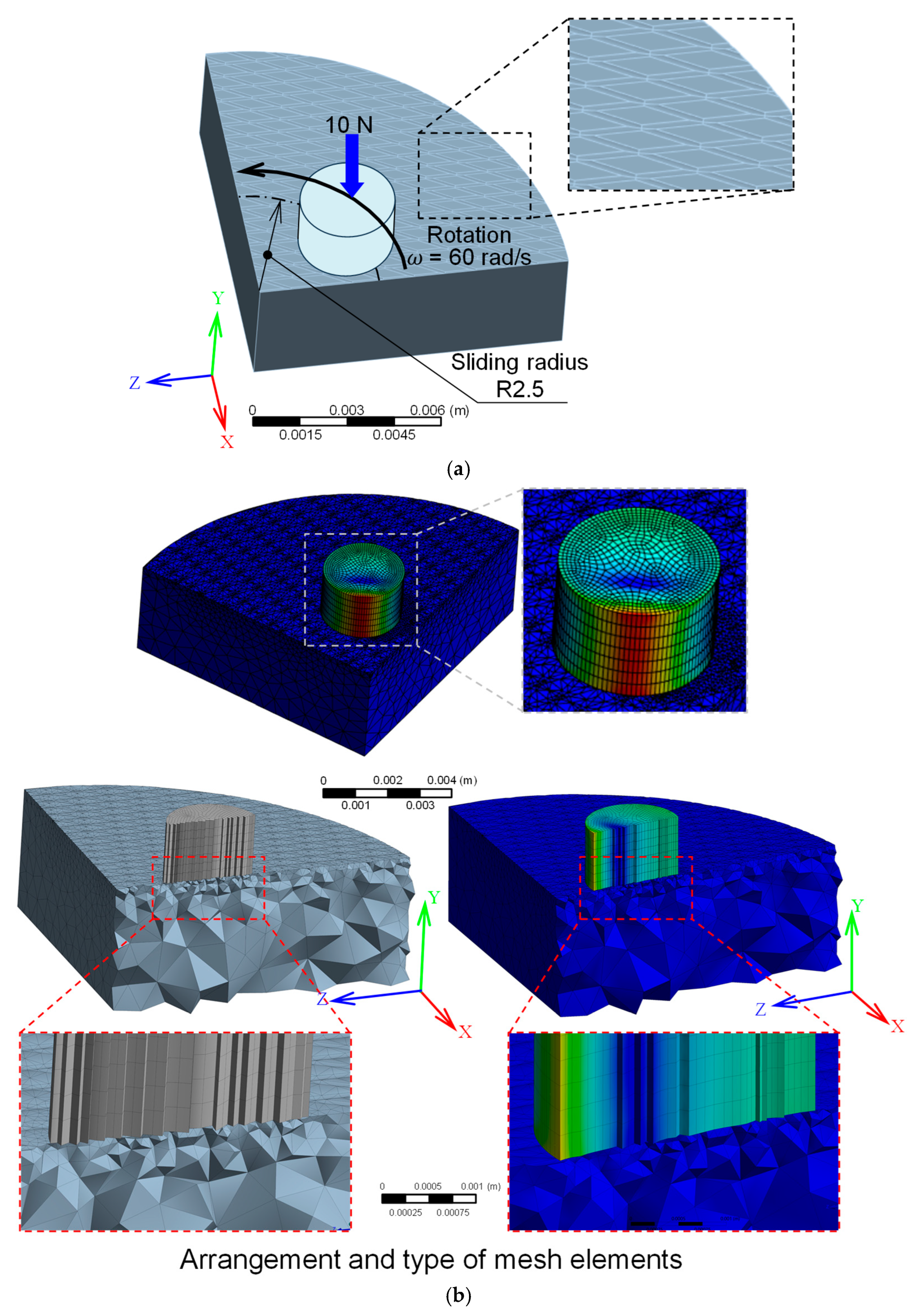
The commercial code Ansys 2024 R1 was employed to perform a transient structural analysis for simulating the pin-on-disc configuration. This simulation aimed to numerically investigate the contact pressure distribution and stress concentration of a high-speed steel surface textured at different crosshatch angles during sliding contact, as shown in Figure 3a. It is important to note that the simulations were not intended to predict wear or friction coefficients directly; rather, they aimed to understand how micro-groove orientations influence the distribution of contact pressure and von Mises stress concentrations during tribological contact. The geometry consisted of a disc made of JIS SKH51 high-speed steel and a cylindrical pin (3 mm in diameter) made of AISI 304 stainless steel in contact with the disc surface. To minimize the computational cost and time, only one-quarter of the disc was modeled, taking advantage of the rotational symmetry of the setup. This is because the contact area of the 3 mm pin behaves consistently across each quarter of the disc.
This pin was positioned 2.5 mm from the disc center to define the contact location, as illustrated in Figure 3a. Micro-grooves with crosshatch angles of 30°, 60°, and 90° and dimensions shown in Figure 2b–d were modeled on the disc surface to reflect the experimental conditions. The materials were defined as elastic–perfectly plastic, assuming no strain hardening and exhibiting isotropic properties. The mechanical properties of JIS SKH51 high-speed steel and AISI 304 stainless steel were obtained from the literature and are listed in Table 1. The mesh was refined near the contact region, as shown in Figure 3b, to ensure accurate stress resolution, particularly at the groove edges, where stress concentrations were expected.
After the disc and pin geometries were defined and their material properties were established, the following boundary and loading conditions were configured for the finite element model. The simulation was performed in two sequential steps. In the first step, the pin was vertically pressed against the disc with a constant normal load of 10 N applied downward to the top surface of the cylindrical pin, as shown in Figure 3a. In the second step, the relative sliding motion between the pin and disc was simulated. Although in the experimental configuration, the disc was rotated while the pin remained stationary, the numerical model was designed such that the disc remained fixed and the pin was rotated instead. This approach not only preserved the same relative motion between the contacting surfaces but also reduced the computational time by limiting the number of moving elements [46]. The pin was rotated around the disc center at a constant angular velocity of 60 rad/s, corresponding to a linear sliding speed of 150 mm/s at a radial distance of 2.5 mm from the center. The following boundary conditions were applied:
Pin constraints: The movement of the pin was allowed in all directions, and the rotational displacement was restricted about the Z- and X- axes while allowing rotation around the disc axis (Y-axis) to simulate the circular sliding motion.
Disc constraints: The disc was fully constrained in all translational and rotational directions to remain fixed during the simulation, reflecting its stationary role in the model.
Contact definition: A surface-to-surface contact interaction was defined between the pin and disc using an elastic contact condition and penalty-based tangential contact model to allow frictional sliding. Because the friction force was not the primary focus of the simulation. A constant friction coefficient of 0.25 was assigned to all surface configurations to enable a controlled comparative analysis of the crosshatch angle effects. This represents a simplification of the complex tribological interactions compared to the reality in which friction coefficients vary with contact pressure, sliding velocity, temperature, and lubrication conditions [47,48]. By maintaining identical friction parameters across all cases, the resulting differences in contact pressure and stress distribution can be directly attributed to the surface texture geometry without interference from the varying friction variables [49]. This approach allows for clear isolation of texture-induced effects on contact mechanics.
These boundary conditions ensured that the pin rotated under the applied normal load, whereas the disc remained stationary, thus replicating the relative sliding contact observed in the pin-on-disc test. The model allowed for the investigation of pressure and stress distribution, with particular attention paid to the contact stress concentrations around the edges of the laser-textured grooves under tribological loading conditions.

3. Results and Discussion

3.1. Effect of Laser Power and Number of Passes on Width and Depth of Micro-Grooves

The groove width and depth increased with increasing laser power, as shown in Figure 4a,b. The predicted values followed the same trend and showed good agreement with the experimental results. This behavior is attributed to the higher heat input at higher power levels, which enhanced material ablation and resulted in larger grooves. The number of passes had a more pronounced effect on the groove depth than on the width. During multipass texturing, the groove dimensions primarily changed along the beam direction for deepening the groove rather than in the lateral direction, which would result in groove widening. Based on the measured groove width and depth, the aspect ratio was calculated and is presented in Figure 4c. As previously mentioned, an aspect ratio of 0.1 is the target of this study, given its strong potential to enhance lubricant retention. According to the results, this target aspect ratio was consistently achieved with minimal variation when a laser power of 20 W and three passes were applied. Under these conditions, the fabricated grooves exhibited an average width of 115.62 µm and a depth of 15.07 µm, leading to an aspect ratio of 0.13, which is nearly identical to the intended value of 0.1. These optimized parameters were therefore selected for preparing the textured samples used in the subsequent tribological tests. Figure 4d shows the groove profile obtained after the texturing. It can be observed that recast structures protruding from the groove edges measured approximately 3 μm in height. Although this recast height is relatively small, the textured surface was polished post-process in this study to fully remove the recast layer and achieve an areal surface roughness (Sa) of approximately 0.1 µm. Furthermore, the numerically predicted groove profile exhibited close agreement with the experimentally measured profile, thereby confirming the reliability and accuracy of the predictive model in representing the groove geometry.

3.2. Effect of Groove Crosshatch Angles on Friction and Wear of High-Speed Steel Surfaces

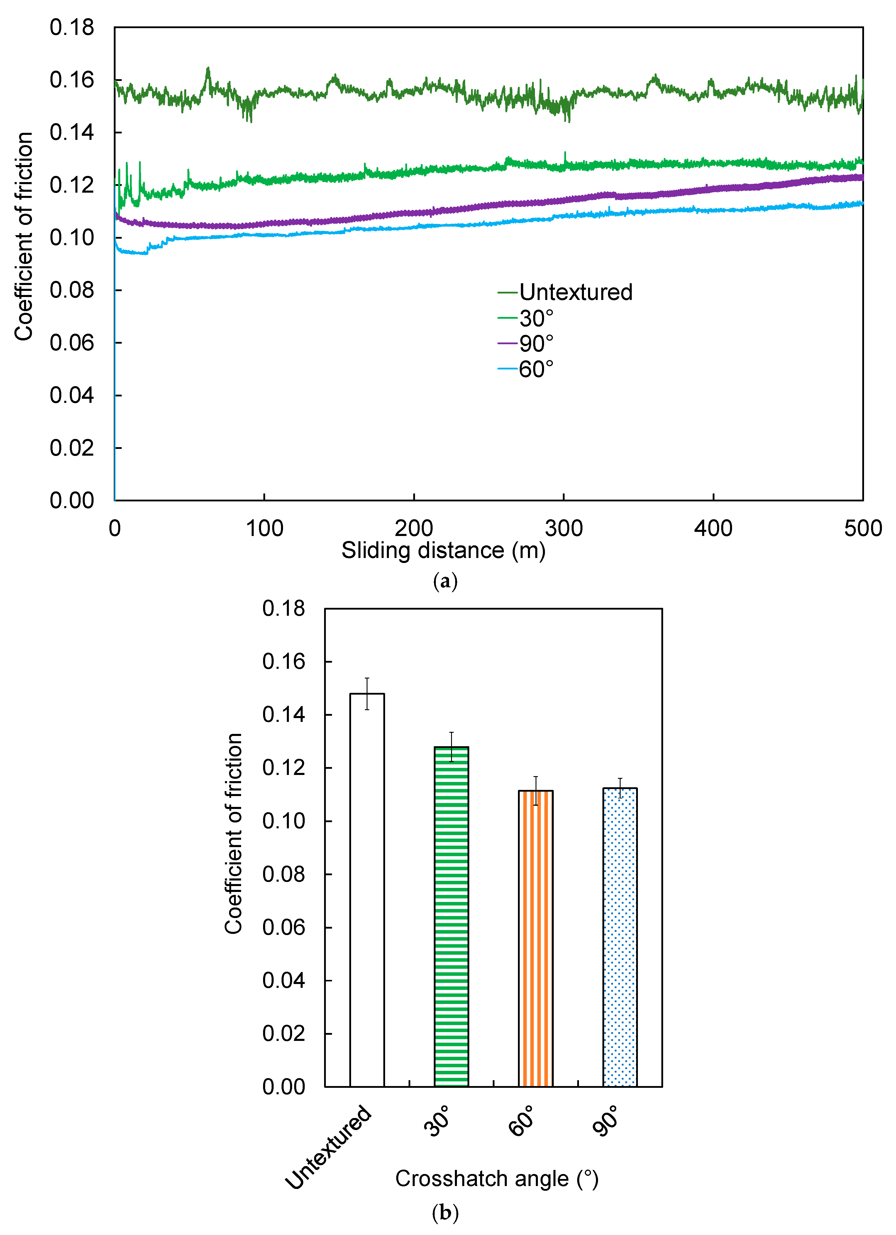
The friction coefficients for laser-textured surfaces with different crosshatch angles, and for a smooth, untextured surface across various sliding distances are presented in Figure 5a. During the initial stage of testing, all the surfaces exhibited a rapid increase in the friction coefficients. The surface with a 90° crosshatch angle showed a decrease in friction as the sliding distance extended to approximately 50 m. After this distance, the friction coefficient for the 90° crosshatch-textured surface began to rise again. The textured surfaces with 30° and 60° crosshatch angles exhibited a gradual increase in the friction coefficients, whereas the untextured surface continued to exhibit high and fluctuating friction levels throughout the test. Across all sliding distances, the textured surfaces exhibited consistently lower friction than the untextured surfaces. This observation suggests that the presence of micro-grooves contributes to enhanced lubricant retention on the surface [13,14]. The retained lubricant is crucial for maintaining a stable lubricating film at the contact interface, in contrast to a smooth surface, which is less capable of sustaining such a film. Furthermore, the flow of lubricant through the textured surfaces induces localized hydrodynamic pressure, which improves the load-carrying capacity between the contact surfaces and further reduces friction [50,51].
The average coefficients of friction obtained from the surfaces textured with different groove crosshatch angles showed that the surface with a 60° crosshatch angle exhibited the lowest friction. The average coefficient of friction for this pattern was 0.111, which was lower than the 0.112 and 0.127 recorded for the 90° and 30° patterns, respectively (Figure 5b). In contrast, the smooth, untextured surface exhibited the highest friction coefficient, recorded at 0.148. Although all textured surfaces had the same groove area density (groove area to total surface area) of 36%, the differences in the crosshatch angles led to different groove area distributions, which significantly affected the friction behavior.
Figure 6 illustrates a schematic representation of the contact regions between the textured surface and sliding pin, emphasizing the differences in the micro-groove distributions across crosshatch angles of 30°, 60°, and 90°. Notably, the surface with a 30° crosshatch angle had a larger flat area than those with 60° and 90° crosshatch angles. These extensive flat regions served as the primary contact areas during sliding. Such regions reduced the ability of the lubricant to spread uniformly across the surface, thereby restricting the formation of a continuous lubricating film. Consequently, a relatively high coefficient of friction was observed for the 30° pattern. The direct observation of the contact interface between a textured tool and work surfaces during the forming process by Shimizu et al. [52] demonstrated that there was less lubricant transfer, and the lubricant failed to reach the nearby micro-lubricant reservoirs for a longer portion of the flat area.
A geometric analysis of the intersection areas formed by the groove patterns further elucidates this behavior. The calculated intersection areas, defined as the overlapping regions of grooves at each crosshatch angle, were 20,000 µm2, 11,547 µm2, and 10,000 µm2 for the 30°, 60°, and 90° angles, respectively. A larger groove intersection area in the 30° pattern implies a higher reservoir volume; however, this larger volume may inhibit the dynamic supply of lubricant to the contact interface, thereby causing higher friction. According to Shimizu et al. [52], an excessive reservoir volume delays the lubricant outflow. This makes it difficult for the lubricant to reach the subsequent reservoir in the sliding direction, resulting in higher friction due to insufficient surface separation. In contrast, the surfaces textured with 60° and 90° crosshatch angles exhibited smaller flat areas and relatively lower groove intersection areas. These configurations allowed for better lubricant flow between the grooves and better retention across the entire contact surface. Additionally, the improved lubricant distribution promoted the generation of localized hydrodynamic pressure, effectively increasing the separation between the contacting surfaces [40], thereby reducing friction more effectively than the 30° pattern.
To quantitatively assess these effects, a schematic geometric analysis was performed to determine the total contact area on the sliding path of the pin at a radial distance of 2.5 mm from the disc center. The model assumed a sliding track width equal to a pin diameter of 3 mm, groove width of 100 µm, and spacing of 500 µm between grooves. The total contact areas during sliding were calculated as 32.80 mm2, 32.72 mm2 and 32.74 mm2 for the 30°, 60°, and 90° crosshatch angles, respectively. Although the differences were small, the slightly lower contact area in the 60° pattern aligned with its lowest recorded friction coefficient, indicating that an optimized groove orientation can improve lubricant performance and frictional behavior.
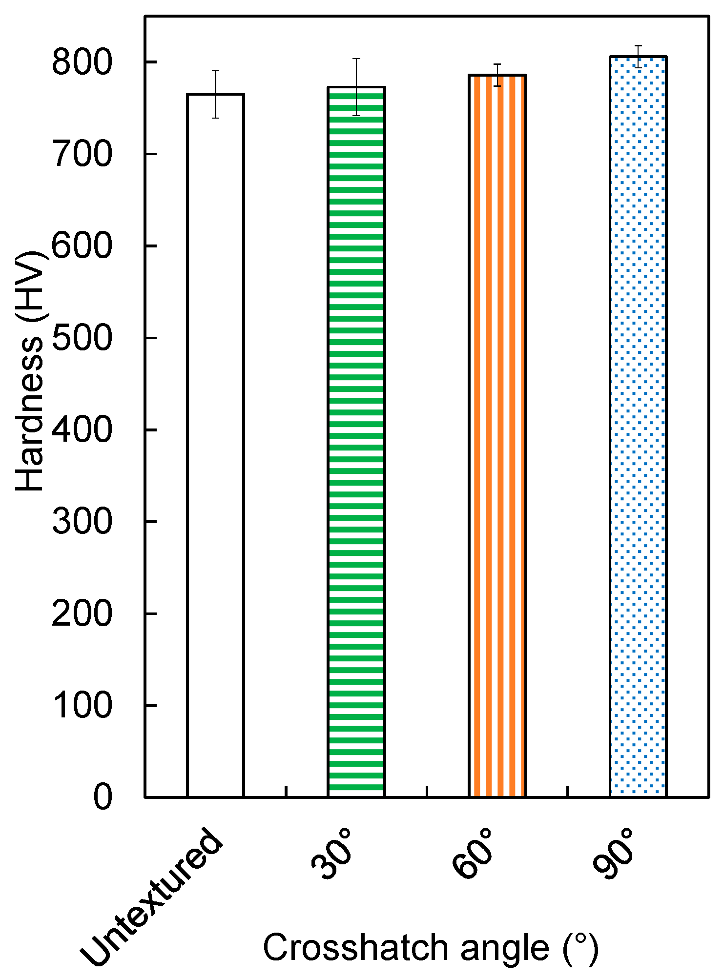
The microhardness values measured near the groove edges of the laser-textured surfaces are shown in Figure 7. Although the average coefficients of friction varied among the surfaces textured with groove crosshatch angles of 30°, 60°, and 90°, the surface hardness values of all textured samples were only slightly higher than that of the untextured surface. This indicates that the increase in surface hardness due to laser texturing was minimal and had a negligible effect on friction reduction. Therefore, in this study, the variation in frictional behavior was primarily attributed to the orientation of the groove crosshatch angle rather than changes in surface hardness.
Following the friction tests, the worn surfaces of the samples were examined using a 3-D laser confocal microscope and an optical microscope to evaluate wear, as illustrated in Figure 8. The observations revealed no significant material loss in the sliding direction on any of the tested surfaces. Only slight surface scratches were observed, which corresponded to abrasive wear. These scratches were attributed to the interaction between the AISI 304 stainless steel pin and the test sample, as well as the presence of loose debris generated during sliding, particularly recast particles located within the grooves. These recast particles, often composed of hard oxide phases, can act as third-body abrasives, contributing to superficial scratching on the textured surface during the pin-on-disc test. The wear features observed were similar across all four surface conditions, regardless of the groove orientation.
However, under the current experimental conditions, it should be noted that with a sliding distance of 500 m, only mild abrasive scratches were observed on the SKH51 steel surfaces, with no measurable material removal. As a result, quantitative measurements of wear width, wear depth, and wear rate were not obtained in this study. Therefore, the influence of laser-textured groove patterns with different crosshatch angles on improving wear resistance could not be clearly demonstrated. Consequently, it remains difficult to conclusively determine whether the presence of laser-textured micro-grooves contributes to a reduction in the wear rate compared to untextured surfaces. Therefore, further investigations are required to address this limitation. Future studies should consider extending the sliding distance beyond 500 m under elevated loading conditions. A comparative analysis of wear volumes between textured and untextured surfaces under more demanding conditions would offer clearer insights into the wear resistance and durability benefits of micro-groove textures. Additionally, high-magnification imaging techniques, such as scanning electron microscopy (SEM), should be employed to provide a more detailed characterization of wear scars and surface damage. Such extended investigations would not only confirm the wear resistance properties of laser-textured surfaces but also help elucidate the additional advantages and limitations of surface texturing beyond its proven effectiveness in reducing the sliding friction.

3.3. Numerical Simulation of Contact Behavior

3.3.1. Mesh Independence Study

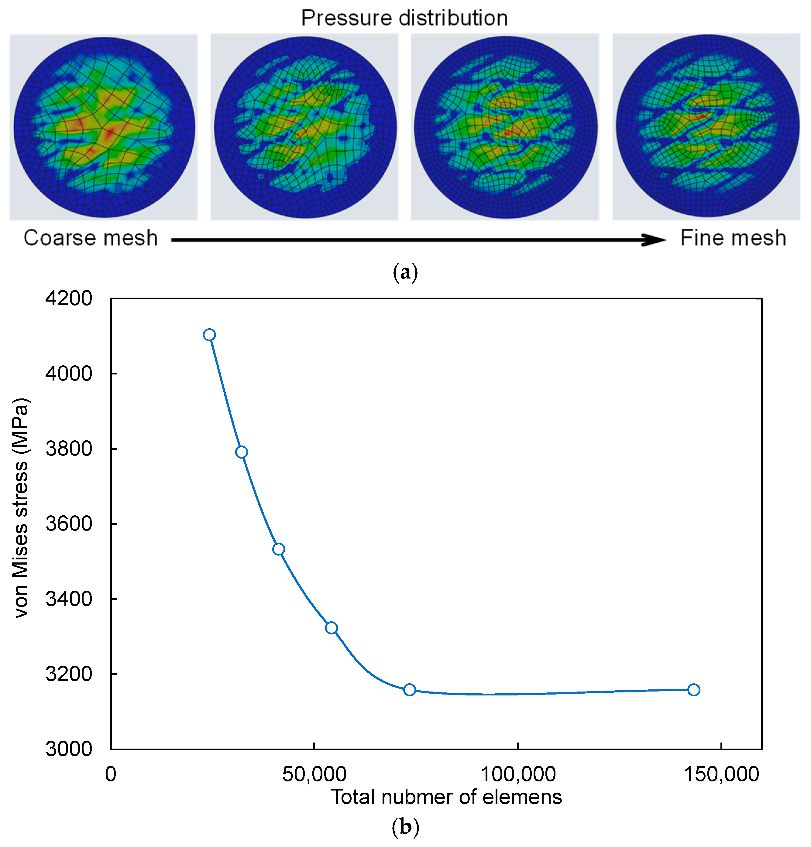
A mesh independence study was conducted to ensure the reliability and accuracy of the numerical simulations. This analysis was performed using a disc model textured with micro-grooves at a 30° crosshatch angle, selected as the representative case. The primary objective was to verify that the simulation results, particularly the von Mises stress, were not significantly influenced by the mesh density. The mesh independence analysis was based on a comparison of the von Mises stress values obtained from different mesh densities while maintaining consistent geometry and boundary conditions. Tetrahedral elements were employed to generate the finite element mesh with local refinement applied in the contact region between the pin and disc to accurately capture the stress gradients, particularly around the groove edges where stress concentrations were expected. Six mesh densities were evaluated, with the total number of elements ranging from 24,231 to 143,294 for both pins and discs. As summarized in Table 4 and illustrated in Figure 9, the von Mises stress decreased and gradually converged with an increase in the mesh refinement. For the coarsest mesh (24,231 elements), the von Mises stress was 4103.28 MPa. As the mesh density increased to 32,120, 41,234, and 54,231 elements, the corresponding von Mises stress values were 3791.26 MPa, 3532.67 MPa, and 3322.68 MPa, resulting in relative differences of 8.23%, 7.32%, and 6.32%, respectively, compared to the previous mesh level. Further refinement to 73,425 elements obtained a stress value of 3157.84 MPa, with an error or tolerance of 5.22%. When the mesh was increased from 73,425 to 143,294 elements, the change in the von Mises stress was only 0.0012%, which is negligible and well below the 0.1% threshold typically used to confirm the mesh convergence.
Figure 9a shows the effect of mesh refinement on the pressure distribution, clearly demonstrating enhanced resolution and sharper pressure gradients with finer meshes. Figure 9b presents the trend of von Mises stress versus the total number of elements, showing a clear convergence behavior of the stress with mesh elements of 73,425 or greater. Thus, it is suggested that simulations with mesh densities equal to or greater than 73,425 elements provide results that are independent of the mesh resolution, with an acceptable balance between computational efficiency and accuracy. This mesh sensitivity analysis validated the reliability of the finite element model in predicting contact-induced stresses and allowed for an accurate evaluation of stress concentrations near textured groove features. Accordingly, a mesh with 73,425 elements was adopted for all subsequent simulations in this study.

3.3.2. Contact Pressure Distribution and Stress Concentration

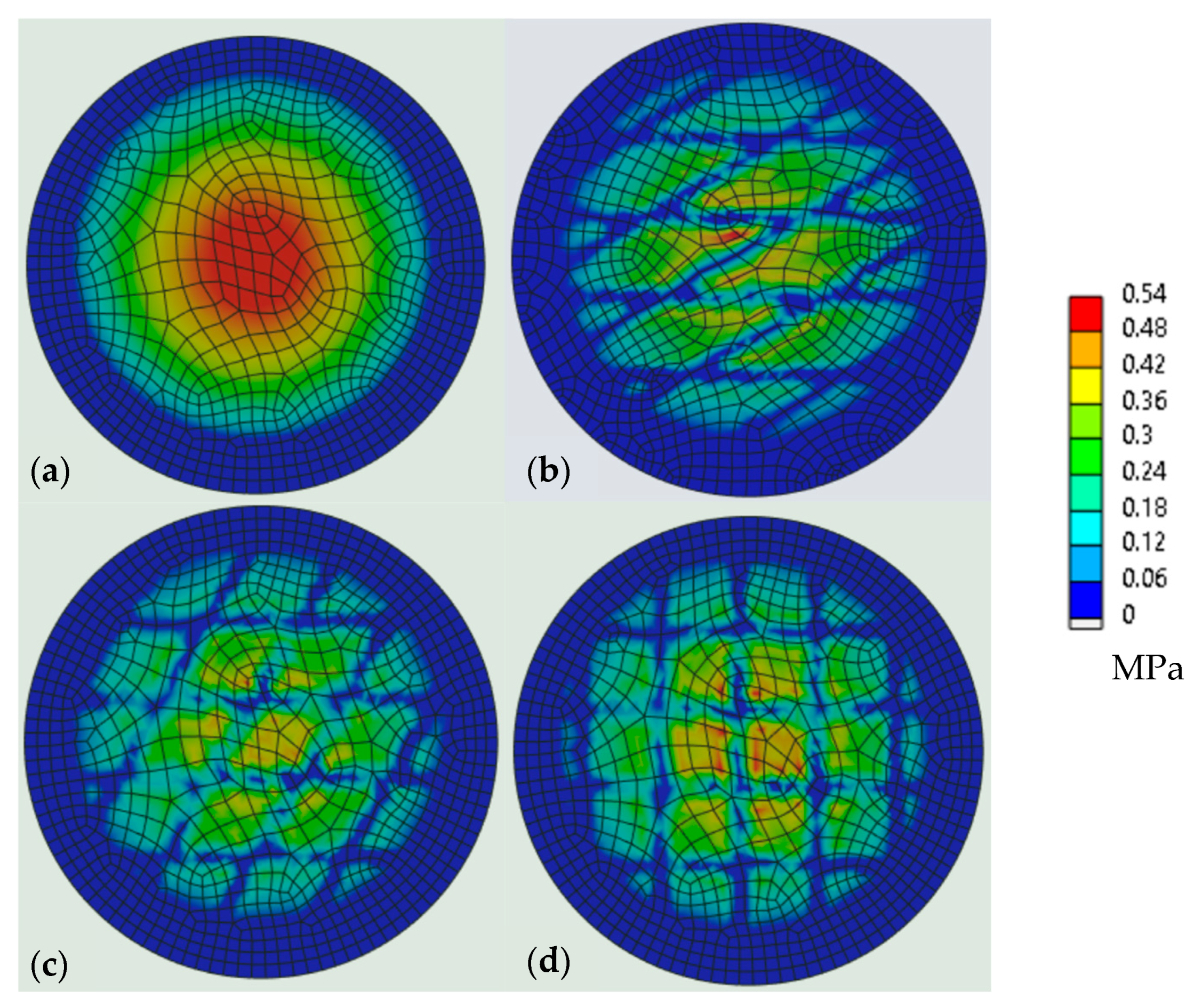
The numerical analysis revealed the distribution of the contact pressure on the disc surface reflected over the pin surfaces during the initial pressing phase (time step 1), as shown in Figure 10. Comparisons were made between untextured and laser-textured discs with groove crosshatch angles of 30°, 60°, and 90°. For the untextured disc (Figure 10a), the contact pressure distribution was nearly uniform and exhibited a symmetrical and continuous pattern across the contact area. The maximum pressure (red zone, 0.54 MPa) was located at the central region of the pin–disc interface and gradually decreased toward the outer edge in a concentric manner. This distribution reflects full surface direct contact and the capability of fully direct centralized load transmission, where no micro-texture exists to redistribute the load.
In contrast, the laser-textured discs (Figure 10b–d) exhibited significantly more heterogeneous pressure distribution patterns, characterized by alternating high- and low-pressure zones that followed the geometry of the textured grooves. Compared to the untextured case, the overall pressure intensity was reduced, while the formation of localized contact points became increasingly prominent. The influence of the groove crosshatch angle was evident, as increasing the angle from 30° to 90° progressively enhanced the pressure distribution heterogeneity. The 30° crosshatch angle (Figure 10b) showed localized concentrations of contact pressure primarily along the acute-angle edges near the center of the pin–disc interface. The 60° pattern (Figure 10c) provided improved load redistribution with a more uniform pressure spread, although slightly localized intensities remained. The 90° crosshatch pattern (Figure 10d) produced the most pronounced pressure concentrations along the groove edges, generating a distinct grid-like distribution of the contact pressure owing to their orthogonal alignment. These findings are consistent with those of Yuan et al. [53] and Wang et al. [54], who observed that textured grooves induced stress concentrations at their edges.
Overall, the results demonstrate that laser surface texturing significantly alters the contact pressure characteristics during the initial loading stage of the tribological test. Whereas the untextured surface exhibited a uniform, centrally concentrated pressure distribution, the textured surfaces promoted heterogeneous and localized pressure zones dictated by the groove geometry. The variation in the crosshatch pattern angles from 30° to 90° exhibited a progressive trend toward a reduced real contact area and increased localized pressure intensity at specific contact points. The observed pressure redistribution mechanisms suggest that surface texturing can be strategically employed to control the local contact pressure concentrations and potentially influence the friction behavior in tribological and forming applications.
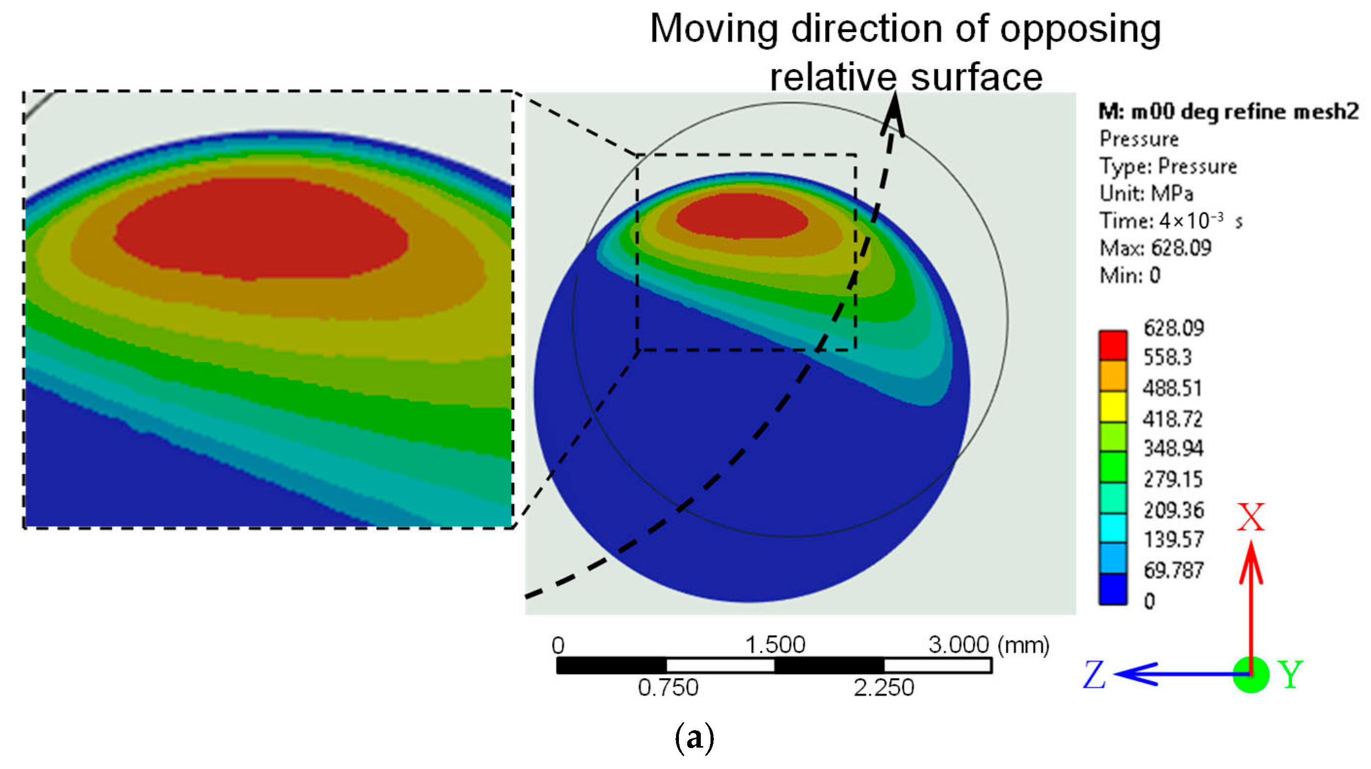
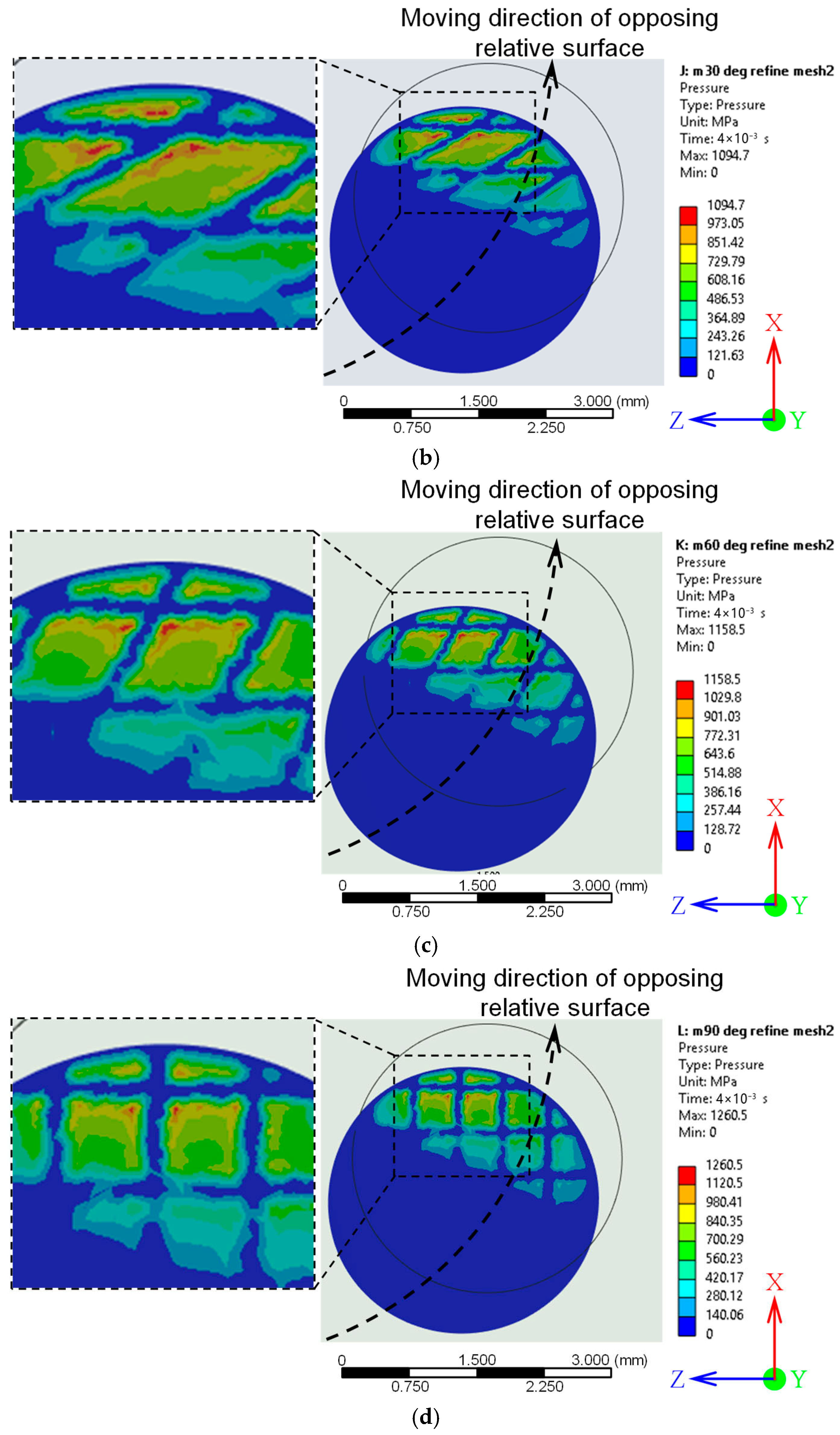
Figure 11 illustrates the contact pressure distribution reflected over the pin surface during the second motion step, corresponding to the relative sliding of the pin against the disc surface for both the untextured and laser-textured discs with groove crosshatch angles of 30°, 60°, and 90°. Similar to the initial pressing phase, the general distribution trends were maintained; however, the region of maximum contact pressure shifted toward the trailing (backside) edge of the pin in the sliding direction owing to the change in the relative motion.
For the untextured surface (Figure 11a), the pressure distribution was characterized by a smooth, continuous gradient, with the highest pressure (red zone, ~628 MPa) concentrated at the trailing edge of the pin–disc contact zone. This pressure gradually decreased toward the surrounding contact area, reflecting uniform load transmission without localized disruption from the surface textures. In contrast, the textured surfaces (Figure 11b–d) exhibited highly heterogeneous pressure patterns with distinct localized high-pressure zones along the groove edges. These localized peaks were primarily located near the trailing edge of the contact interface relative to the sliding direction and were oriented perpendicular to the sliding direction, where the groove–asperity interactions intensified the contact stress. These concentrations arose from the geometric discontinuities introduced by the micro-grooves, which disrupted the otherwise uniform pressure field. All textured configurations reduced the overall real contact area compared to the untextured surface, leading to sharper pressure gradients and more pronounced stress concentration sites.
The 30° crosshatch pattern (Figure 11b) produced moderately localized high-pressure zones, with the maximum value reaching ~1094.7 MPa, distributed along the oblique groove edges. The 60° configuration (Figure 11c) exhibits a greater degree of localization, with more clearly defined pressure peaks (~1158.5 MPa). The 90° crosshatch pattern (Figure 11d) demonstrates the most distinct grid-like arrangement of high-pressure zones, with pronounced peaks (~1260.5 MPa) concentrated at the groove corners, which is consistent with the symmetrical orthogonal groove layout.
These observations show that while surface texturing increases localized peak pressures compared to untextured surfaces, it also disrupts the continuity of high-pressure regions, potentially altering the contact of the pin-disc interface. These findings are consistent with those of previous studies [53,54], which reported that high-stress concentration regions were located at the groove edge. This effect was particularly pronounced when the grooves were oriented perpendicular to the sliding direction.
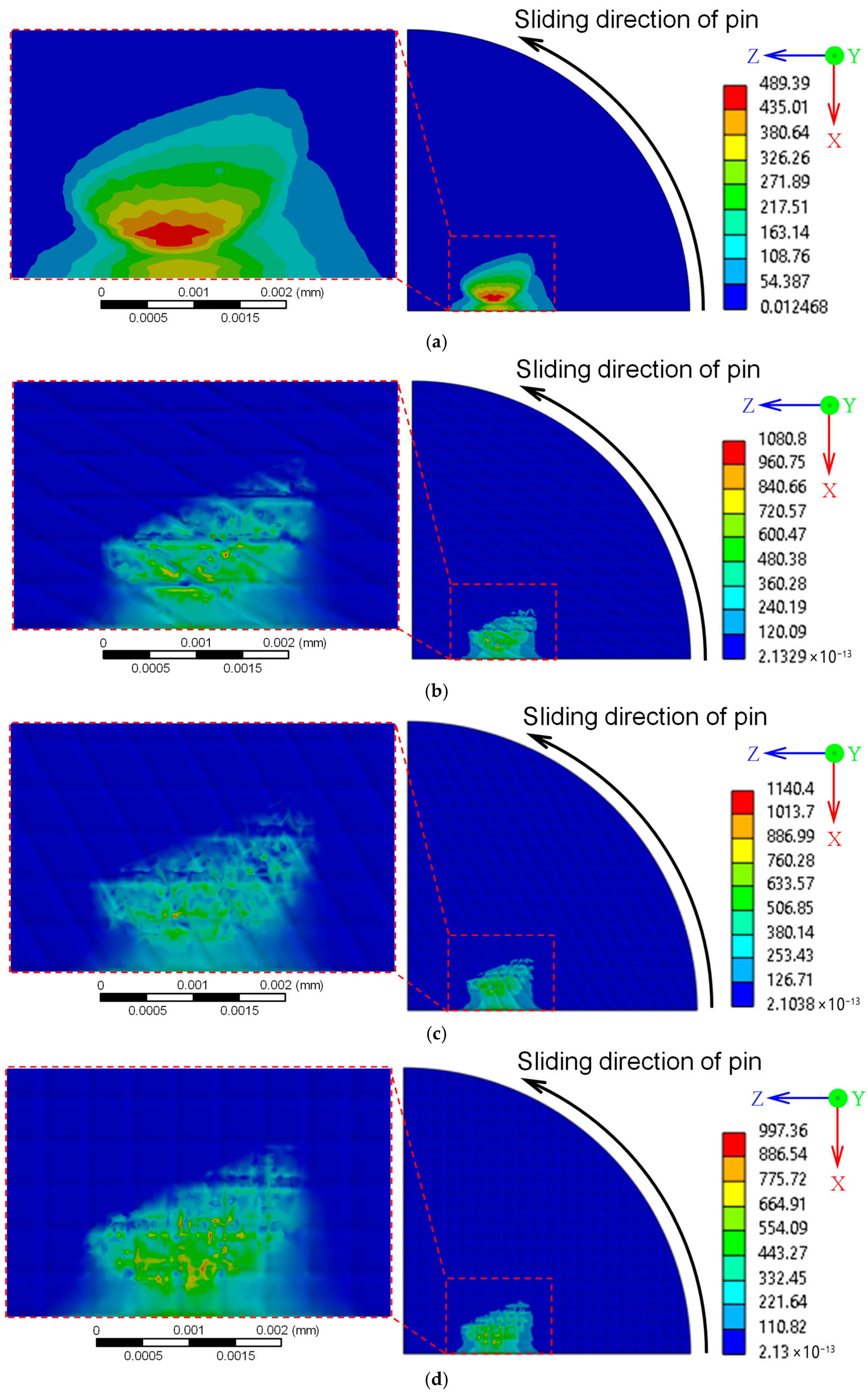
The corresponding von Mises stress distributions during the second phase of motion, when the pin slid relative to the disc, are shown in Figure 12. In all cases, the highest stress intensities occurred at the trailing edge of the contact interface between the pin and the disc. The untextured disc (Figure 12a) exhibited the lowest maximum von Mises stress, which was concentrated near the backside of the contact area beneath the sliding path with a relatively uniform distribution. In contrast, the laser-textured discs (Figure 12b–d) displayed significantly higher localized stress peaks, particularly concentrated at the corners of the groove edges. This behavior aligns with the findings of Yuan et al. [53] and Wang et al. [54], who reported that sharp texture boundaries act as stress concentrators, amplifying von Mises stresses.
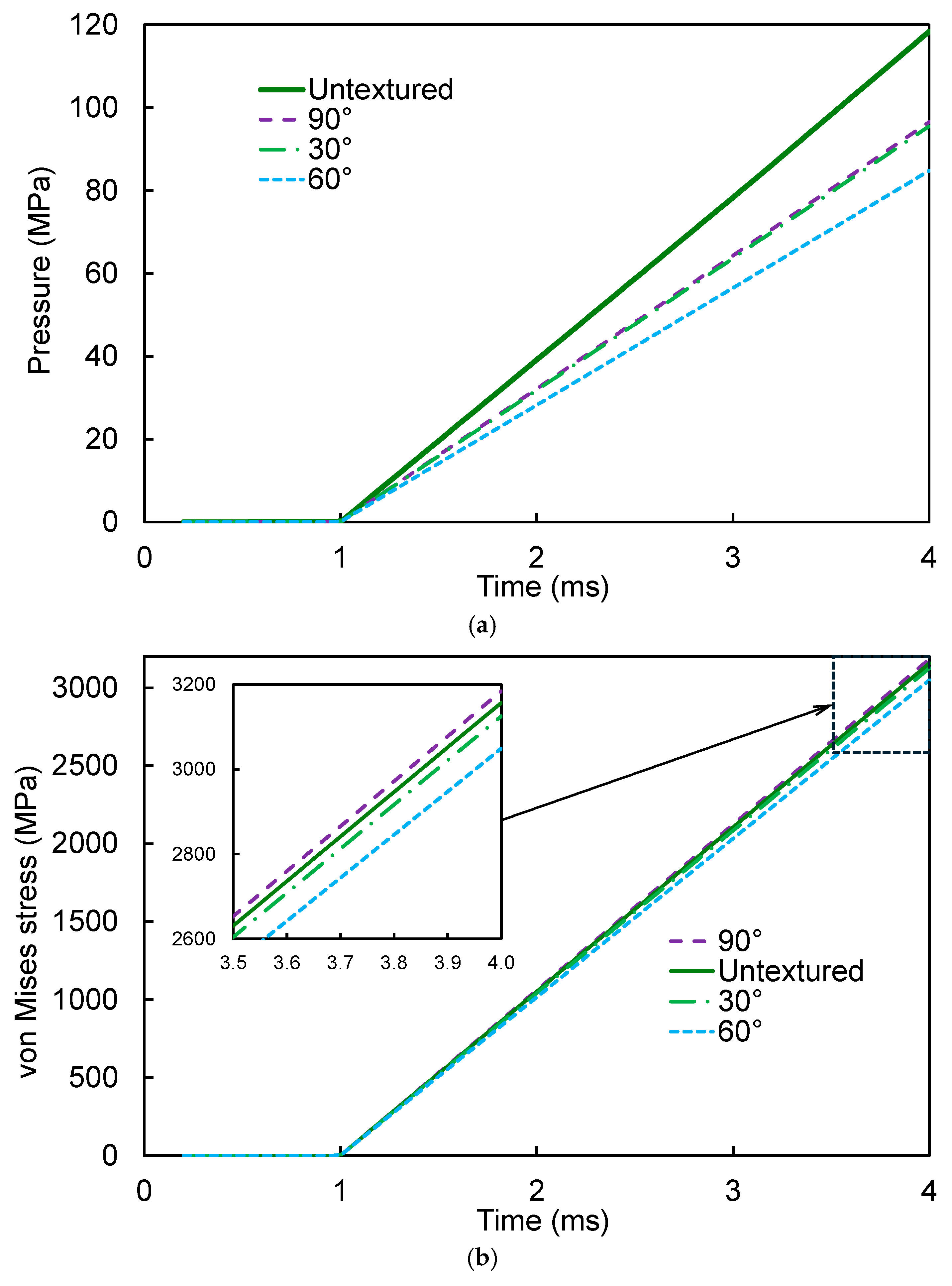
Figure 13 presents the average contact pressure and von Mises stress over time for the untextured and laser-textured discs with groove crosshatch angles of 30°, 60°, and 90°. During the initial pressing step (0–1 ms), both pressure and stress increased linearly as the normal load was applied, with only minimal differences observed among the various surface conditions of the samples. However, once sliding began (1–4 ms), the effect of groove orientation became more pronounced. At the final time step (4 ms), the 60° crosshatch pattern exhibited the lowest average contact pressure and von Mises stress, followed by the 30° pattern, whereas the 90° crosshatch angle and untextured surface exhibited higher values. The reduction in both pressure and stress for the 60° texture suggests more load redistribution and a decrease in the real contact area, which can reduce the adhesive contact and frictional forces. This behavior correlates with the experimental observation of reduced friction coefficients for the 60° pattern, suggesting that improved load redistribution, lower contact pressure, and stress contribute to enhanced the tribological performance.
The quantitative results at the last time step, summarized in Table 5, present the average contact pressure and average von Mises stress for the untextured and laser-textured discs with different groove crosshatch angles. The groove orientation significantly influenced the average contact pressure across the tested surfaces. The untextured surface exhibited the highest average contact pressure at 118.38 MPa, whereas the introduction of textured groove patterns led to a consistent reduction in contact pressure. Among the textured configurations, the 60° crosshatch pattern demonstrated the lowest contact pressure at 84.79 MPa, followed by the 30° (95.53 MPa) and 90° (96.52 MPa) patterns. Significantly, the 60° crosshatch orientation resulted in a 28% reduction in the average pressure compared to that of the untextured surface. This reduction was attributed to more effective load redistribution and a decrease in the real contact area owing to the influence of the groove geometry [36]. A similar trend was observed for the von Mises stress. The 60° crosshatch angle exhibited the lowest average von Mises stress (3048.9 MPa), representing a substantial stress reduction compared to the untextured disc (3156.9 MPa). The 30° crosshatch orientation showed a moderate reduction to 3125.0 MPa, whereas the 90° crosshatch pattern displayed a slightly elevated stress level (3184.0 MPa), which was higher than that of the untextured case.
The shift from a uniform pressure distribution in the untextured case to localized pressure concentrations on the textured surfaces signifies a transition from full to partial contact mechanics. While localized high-pressure zones at groove edges may intensify stress concentrations, they also simultaneously promote load redistribution, reduce the mean pressure, and enhance tribological performance by reducing adhesive contact. Among the tested geometries, the 60° crosshatch angle appeared to offer the most favorable balance between reducing the mean contact pressure and maintaining efficient load support, which is in agreement with previous tribological findings on the influence of groove orientation [30,36]. This illustrates the potential of laser surface texturing as a design strategy for optimizing contact mechanics in applications where friction reduction is critical.

4. Conclusions

In this study, the effects of laser-textured groove patterns with varying crosshatch angles on the frictional performance, contact pressure distribution, and stress concentration of JIS SKH51 high-speed steel surfaces were experimentally and numerically investigated. Laser surface texturing was performed using different laser powers and passes to produce grooves of controlled width and depth, and tribological tests and finite element simulations were employed to evaluate friction reduction, wear resistance, and contact mechanics. The following conclusions can be drawn based on the experimental and numerical results:
(1)
A higher laser power led to a simultaneous increase in the groove width and depth, whereas increasing the number of passes primarily increased the groove depth with minimal influence on the groove width. The numerical predictions closely matched the experimental measurements, confirming the reliability of the predictive model for groove geometry.
(2)
Laser processing at 20 W with three passes produced grooves with an average width of 115.62 μm and a depth of 15.07 μm, resulting in an aspect ratio of 0.13, which is close to the target value of 0.1 with minimal variation.
(3)
Among the tested geometries, the 60° crosshatch pattern achieved the lowest average coefficient of friction of 0.111, representing a 25% reduction compared with the untextured surface, which had a friction coefficient of 0.148. It was also superior to the 30° pattern, which had a coefficient of 0.127, and the 90° pattern, which had a friction coefficient of 0.112.
(4)
Variations in the crosshatch angle produced small differences in the total contact area but significantly affected the distribution of flat contact zones. A more uniform and well-distributed flat contact area contributed to improved friction performance.
(5)
Pin-on-disc testing over a sliding distance of 500 m showed no measurable material loss from the SKH51 surface, with only minor surface scratching observed.
(6)
Finite element analysis revealed that the laser-textured surfaces disrupted the uniform pressure distribution of the untextured surfaces, producing heterogeneous, localized high-stress zones along the groove edges. The orientation of laser-textured micro-grooves significantly influenced both average contact pressure and von Mises stress during sliding contact. Among the tested configurations, the 60° crosshatch angle exhibited the lowest average contact pressure (84.79 MPa) and average von Mises stress (3048.9 MPa), with a reduction in contact pressure of approximately 28% compared to the untextured surface (118.38 MPa). The 60° crosshatch pattern provided the most balanced combination of load redistribution, reduced mean pressure and average stress, which may reduce friction during service.
These findings enhance the understanding of how groove patterns with varying crosshatch angles influence frictional behavior under lubricated conditions, offering practical guidelines for minimizing sliding friction in deep drawing processes. The observed friction reduction achieved through the optimized groove orientations shows promising potential for lowering the forming loads in sheet metal forming applications.
Although the current study demonstrates the tribological and mechanical advantages of laser-textured groove patterns, further research is recommended to investigate the long-term durability of textured surfaces under extended sliding and high load conditions. For a more comprehensive analysis, numerical models should incorporate pressure-dependent or experimentally derived friction coefficients under realistic lubrication and temperature conditions. Moreover, three-dimensional computational fluid dynamics (CFD) simulations are recommended to reveal the underlying mechanisms of lubricant flow within micro-textured grooves and their influence on the load-carrying capacity and lubrication performance.

Author Contributions

Conceptualization, V.S. and W.D.; methodology, V.S., W.D. and P.V.; software, P.V.; validation, V.S., W.D., P.V., H.Z., H.Q. and H.M.; formal analysis, W.D., V.S., P.V., H.Z., H.Q. and H.M.; investigation, V.S. and W.D.; writing—original draft preparation, V.S., W.D. and P.V.; writing—review and editing, V.S., W.D., P.V., H.Z., H.Q. and H.M.; visualization, V.S., W.D. and P.V.; supervision, V.S. and W.D.; project administration, W.D.; funding acquisition, W.D. All authors have read and agreed to the published version of the manuscript.

Funding

This research was supported by Rajamangala University of Technology Isan and Thailand Science Research and Innovation Fund, agreement No. FF68/NKR/111.

Data Availability Statement

The original contributions presented in the study are included in the article. Further inquiries can be directed to the corresponding authors.

Acknowledgments

The authors would like to express their appreciation to Department of Industrial Engineering and Faculty of Engineering and Technology, Rajamangala University of Technology Isan for supporting this research. During the preparation of this manuscript, the author used ChatGPT 4o to improve readability and language. The authors have reviewed and edited the output and take full responsibility for the content of this publication.

Conflicts of Interest

The authors declare no conflicts of interest.

References

  1. Nielsen, C.V.; Bay, N. Review of Friction Modeling in Metal Forming Processes. J. Mater. Process. Technol. 2018, 255, 234–241. [Google Scholar] [CrossRef]
  2. Tamaoki, K.; Manabe, K.; Kataoka, S.; Aizawa, T. Continuous Dry Cylindrical and Rectangular Deep Drawing by Electroconductive Ceramic Dies. J. Manuf. Sci. Eng. 2013, 135, 031010. [Google Scholar] [CrossRef]
  3. Abe, Y.; Mori, K.; Hatashita, F.; Shiba, T.; Daodon, W.; Osakada, K. Improvement of Seizure Resistance in Ironing of Stainless Steel Cup with Cermet Die Having Fine Lubricant Pockets. J. Mater. Process. Technol. 2016, 234, 195–207. [Google Scholar] [CrossRef]
  4. Zhai, W.; Bai, L.; Zhou, R.; Fan, X.; Kang, G.; Liu, Y.; Zhou, K. Recent Progress on Wear-Resistant Materials: Designs, Properties, and Applications. Adv. Sci. 2021, 8, 2003739. [Google Scholar] [CrossRef] [PubMed]
  5. Hacisalihoglu, I.; Yildiz, F.; Alsaran, A. Wear Performance of Different Nitride-Based Coatings on Plasma Nitrided AISI M2 Tool Steel in Dry and Lubricated Conditions. Wear 2017, 384–385, 159–168. [Google Scholar] [CrossRef]
  6. Kumar, A.; Kaur, M.; Joseph, A.; Jhala, G. Surface Engineering Analysis of Plasma-Nitrided Die Steels. Proc. Inst. Mech. Eng. Part J J. Eng. Tribol. 2019, 234, 917–931. [Google Scholar] [CrossRef]
  7. Podgornik, B.; Hogmark, S.; Sandberg, O. Proper Coating Selection for Improved Galling Performance of Forming Tool Steel. Wear 2006, 261, 15–21. [Google Scholar] [CrossRef]
  8. Trzepieciński, T. Approaches for Preventing Tool Wear in Sheet Metal Forming Processes. Machines 2023, 11, 616. [Google Scholar] [CrossRef]
  9. Bay, N.; Azushima, A.; Groche, P.; Ishibashi, I.; Merklein, M.; Morishita, M.; Nakamura, T.; Schmid, S.; Yoshida, M. Environmentally Benign Tribo-Systems for Metal Forming. CIRP Ann. 2010, 59, 760–780. [Google Scholar] [CrossRef]
  10. Adamus, J.; Więckowski, W.; Lacki, P. Analysis of the Effectiveness of Technological Lubricants with the Addition of Boric Acid in Sheet Metal Forming. Materials 2023, 16, 5125. [Google Scholar] [CrossRef]
  11. Dhage, S.; Jayal, A.D.; Sarkar, P. Effects of Surface Texture Parameters of Cutting Tools on Friction Conditions at Tool-Chip Interface during Dry Machining of AISI 1045 Steel. Procedia Manuf. 2019, 33, 794–801. [Google Scholar] [CrossRef]
  12. Guo, D.; Wang, D.; Wu, S.; Qi, H.; Saetang, V. Investigation on Turning of Inconel 718 Using Differently Coated Microtextured Tools. Proc. Inst. Mech. Eng. Part E J. Process Mech. Eng. 2025, 239, 754–764. [Google Scholar] [CrossRef]
  13. Etsion, I. State of the Art in Laser Surface Texturing. J. Tribol. 2005, 127, 248. [Google Scholar] [CrossRef]
  14. Costa, H.L.; Hutchings, I.M. Effects of Die Surface Patterning on Lubrication in Strip Drawing. J. Mater. Process. Technol. 2009, 209, 1175–1180. [Google Scholar] [CrossRef]
  15. Tang, W.; Zhou, Y.; Zhu, H.; Yang, H. The Effect of Surface Texturing on Reducing the Friction and Wear of Steel under Lubricated Sliding Contact. Appl. Surf. Sci. 2013, 273, 199–204. [Google Scholar] [CrossRef]
  16. Byun, J.W.; Shin, H.S.; Kwon, M.H.; Kim, B.H.; Chu, C.N. Surface Texturing by Micro ECM for Friction Reduction. Int. J. Precis. Eng. Manuf. 2010, 11, 747–753. [Google Scholar] [CrossRef]
  17. Costa, H.; Hutchings, I. Some Innovative Surface Texturing Techniques for Tribological Purposes. Proc. Inst. Mech. Eng. Part J J. Eng. Tribol. 2014, 229, 429–448. [Google Scholar] [CrossRef]
  18. Mankeekar, T.; Bähre, D.; Durneata, D.; Hall, T.; Lilischkis, R.; Natter, H.; Saumer, M. Fabrication of Micro-Structured Tools for the Production of Curved Metal Surfaces by Pulsed Electrochemical Machining. Int. J. Adv. Manuf. Technol. 2021, 119, 2825–2833. [Google Scholar] [CrossRef]
  19. Zhu, H.; Jiang, Z.; Han, J.; Saetang, V.; Xu, K.; Liu, Y.; Zhang, Z.; Huang, S.; Zhou, J. Fabrication of Oxide-Free Dimple Structure on Germanium via Electrochemical Jet Machining Enhanced by Opposing Laser Irradiation. J. Manuf. Process. 2022, 85, 623–635. [Google Scholar] [CrossRef]
  20. Singh, M.; Jain, V.K.; Ramkumar, J. Micro-Texturing on Flat and Cylindrical Surfaces Using Electric Discharge Micromachining. J. Micromanuf. 2020, 4, 127–137. [Google Scholar] [CrossRef]
  21. Su, X.; Shi, L.; Huang, W.; Wang, X. A Multi-Phase Micro-Abrasive Jet Machining Technique for the Surface Texturing of Mechanical Seals. Int. J. Adv. Manuf. Technol. 2016, 86, 2047–2054. [Google Scholar] [CrossRef]
  22. Kasem, H.; Stav, O.; Grützmacher, P.; Gachot, C. Effect of Low Depth Surface Texturing on Friction Reduction in Lubricated Sliding Contact. Lubricants 2018, 6, 62. [Google Scholar] [CrossRef]
  23. Mao, B.; Siddaiah, A.; Liao, Y.; Menezes, P.L. Laser Surface Texturing and Related Techniques for Enhancing Tribological Performance of Engineering Materials: A Review. J. Manuf. Process. 2020, 53, 153–173. [Google Scholar] [CrossRef]
  24. Daodon, W.; Saetang, V. Improvement of Frictional Property of AISI D2 Tool Steel Surface against JIS SPFC 980Y Advanced High-Strength Steel by Using Laser Texturing Process. Lubricants 2023, 11, 68. [Google Scholar] [CrossRef]
  25. Kovalchenko, A.; Ajayi, O.; Erdemir, A.; Fenske, G.; Etsion, I. The Effect of Laser Surface Texturing on Transitions in Lubrication Regimes during Unidirectional Sliding Contact. Tribol. Int. 2005, 38, 219–225. [Google Scholar] [CrossRef]
  26. Ryk, G.; Etsion, I. Testing Piston Rings with Partial Laser Surface Texturing for Friction Reduction. Wear 2006, 261, 792–796. [Google Scholar] [CrossRef]
  27. Wang, S.; Wang, W.; Xu, Y.; Zhang, X.; Chen, C.; Geng, P.; Ma, N. Effect of Nanosecond Pulsed Laser Parameters on Texturing Formation of Metallic Surface: Experiment and Modelling. J. Mater. Res. Technol. 2023, 26, 7775–7788. [Google Scholar] [CrossRef]
  28. Zhu, H.; Shen, Y.; Sun, H.; Zhang, Z.; Jin, C.; Ge, S.; Xu, K.; Liu, Y.; Wang, J.; Gu, Q. Ultrafast Laser-Driven Precision Removal of Silver Coatings on Ceramic Substrates: Synergistic Experimental Investigation and TTM Simulation. Int. J. Heat Mass Transf. 2026, 255, 127758. [Google Scholar] [CrossRef]
  29. Zhu, H.; Mao, D.; Lu, X.; Zhang, Z.; Xu, K.; Liu, Y.; Wang, J.; Saetang, V. Synergistic Post-Processing of Micro-Through-Slot Sidewalls in Si Wafers via Hybrid Laser-Electrochemical-Abrasive Method: Mechanism Investigation and Process Simulation. J. Manuf. Process. 2025, 149, 486–501. [Google Scholar] [CrossRef]
  30. Fouathiya, A.; Meziani, S.; Sahli, M.; Barrière, T. Experimental Investigation of Microtextured Cutting Tool Performance in Titanium Alloy via Turning. J. Manuf. Process. 2021, 69, 33–46. [Google Scholar] [CrossRef]
  31. Schneider, J.; Braun, D.; Greiner, C. Laser Textured Surfaces for Mixed Lubrication: Influence of Aspect Ratio, Textured Area and Dimple Arrangement. Lubricants 2017, 5, 32. [Google Scholar] [CrossRef]
  32. Geiger, M.; Popp, U.; Engel, U. Excimer Laser Micro Texturing of Cold Forging Tool Surfaces-Influence on Tool Life. CIRP Ann. 2002, 51, 231–234. [Google Scholar] [CrossRef]
  33. Popp, U.; Engel, U. Microtexturing of Cold-Forging Tools-Influence on Tool Life. Proc. Inst. Mech. Eng. Part B J. Eng. Manuf. 2006, 220, 27–33. [Google Scholar] [CrossRef]
  34. Wagner, K.; Völkl, R.; Engel, U. Tool Life Enhancement in Cold Forging by Locally Optimized Surfaces. J. Mater. Process. Technol. 2008, 201, 2–8. [Google Scholar] [CrossRef]
  35. Meng, F.; Zhou, R.; Davis, T.; Cao, J.; Wang, Q.J.; Hua, D.; Liu, J. Study on Effect of Dimples on Friction of Parallel Surfaces under Different Sliding Conditions. Appl. Surf. Sci. 2010, 256, 2863–2875. [Google Scholar] [CrossRef]
  36. Wang, Z.; Li, Y.; Bai, F.; Wang, C.; Zhao, Q. Angle-Dependent Lubricated Tribological Properties of Stainless Steel by Femtosecond Laser Surface Texturing. Opt. Laser Technol. 2016, 81, 60–66. [Google Scholar] [CrossRef]
  37. Wang, H.; Tian, L.; Zheng, J.; Yang, D.; Zhang, Z. The Synergetic Effects of Laser Texturing and Super-Hydrophobic Coatings on Improving Wear Properties of Steel. Tribol. Int. 2022, 173, 107657. [Google Scholar] [CrossRef]
  38. Wu, Z.; Yuan, C.; Guo, Z.; Huang, Q. Effect of the Groove Parameters on the Lubricating Performance of the Water-Lubricated Bearing under Low Speed. Wear 2023, 522, 204708. [Google Scholar] [CrossRef]
  39. Meng, R.; Deng, J.; Duan, R.; Liu, Y.; Zhang, G. Modifying Tribological Performances of AISI 316 Stainless Steel Surfaces by Laser Surface Texturing and Various Solid Lubricants. Opt. Laser Technol. 2019, 109, 401–411. [Google Scholar] [CrossRef]
  40. Segu, D.Z.; Chae, Y.; Lee, S.-J.; Kim, C.-L. Synergistic Influences of Laser Surface Texturing and ZrO2-MoDTC Hybrid Nanofluids for Enhanced Tribological Performance. Tribol. Int. 2023, 183, 108377. [Google Scholar] [CrossRef]
  41. Niu, Y.; Pang, X.; Yue, S.; Shangguan, B.; Zhang, Y. The Friction and Wear Behavior of Laser Textured Surfaces in Non-Conformal Contact under Starved Lubrication. Wear 2021, 476, 203723. [Google Scholar] [CrossRef]
  42. Phun, C.; Daodon, W.; Septham, K.; Kumkhuntod, P.; Zhu, H.; Saetang, V. Laser-Fabricated Micro-Dimples for Improving Frictional Property of SKH51 Tool Steel Surfaces. Lubricants 2023, 11, 456. [Google Scholar] [CrossRef]
  43. Online Materials Information Resource–MatWeb. Available online: http://www.matweb.com (accessed on 24 December 2024).
  44. Karunathilaka, N.; Tada, N.; Uemori, T.; Hanamitsu, R.; Kawano, M. Effect of Contact Pressure Applied on Tool Surface during Cold Forging on Fatigue Life of Tool Steel. Procedia Manuf. 2018, 15, 488–495. [Google Scholar] [CrossRef]
  45. Properties and Selection: Irons, Steels, and High-Performance Alloys. In Metals Handbook, 10th ed.; ASM International: Materials Park, OH, USA, 1990; Volume 1.
  46. Torres Pérez, A.; García-Atance Fatjó, G.; Hadfield, M.; Austen, S. A Model of Friction for a Pin-On-Disc Configuration with Imposed Pin Rotation. Mech. Mach. Theory 2011, 46, 1755–1772. [Google Scholar] [CrossRef]
  47. Bhushan, B. Modern Tribology Handbook/Vol. 1, Principles of Tribology; CRC Press LLC: Boca Raton, FL, USA, 2001. [Google Scholar]
  48. Zmitrowicz, A. Models of Kinematics Dependent Anisotropic and Heterogeneous Friction. Int. J. Solids Struct. 2006, 43, 4407–4451. [Google Scholar] [CrossRef]
  49. Greenwood, J.A.; Williamson, J.B.P. Contact of Nominally Flat Surfaces. Proc. R. Soc. Lond. Ser. A. Math. Phys. Sci. 1966, 295, 300–319. [Google Scholar] [CrossRef]
  50. Etsion, I.; Halperin, G.; Brizmer, V.; Kligerman, Y. Experimental Investigation of Laser Surface Textured Parallel Thrust Bearings. Tribol. Lett. 2004, 17, 295–300. [Google Scholar] [CrossRef]
  51. Abe, Y.; Sugiura, M.; Ando, T.; Kumkhuntod, P.; Septham, K.; Daodon, W.; Mori, K. Improvement of Seizure Resistance in Ironing of Aluminum Alloy Sheets and Stainless Steel Cups by Utilizing Laser Textured Die Having Lubricant Pockets. Metals 2023, 13, 803. [Google Scholar] [CrossRef]
  52. Shimizu, T.; Kobayashi, H.; Vorholt, J.; Yang, M. Lubrication Analysis of Micro-Dimple Textured Die Surface by Direct Observation of Contact Interface in Sheet Metal Forming. Metals 2019, 9, 917. [Google Scholar] [CrossRef]
  53. Yuan, S.; Huang, W.; Wang, X. Orientation Effects of Micro-Grooves on Sliding Surfaces. Tribol. Int. 2011, 44, 1047–1054. [Google Scholar] [CrossRef]
  54. Wang, X.; Wang, J.; Zhang, B.; Huang, W. Design Principles for the Area Density of Dimple Patterns. Proc. Inst. Mech. Eng. Part J J. Eng. Tribol. 2014, 229, 538–546. [Google Scholar] [CrossRef]
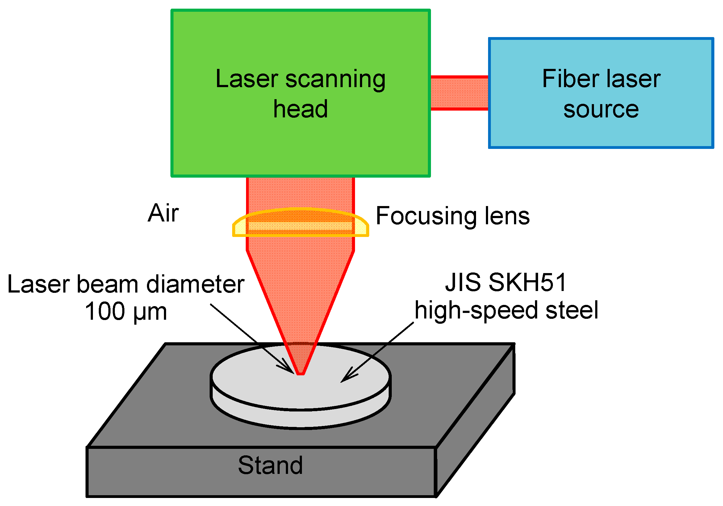
Figure 1. Schematic of laser texturing.
Lubricants 13 00419 g001
Figure 2. (a) Schematic diagram of friction test with pin-on-disc configuration, micro-grooves with crosshatch angles of (b) 30°, (c) 60° and (d) 90°.
Lubricants 13 00419 g002
Figure 3. (a) Geometrical model of pin-on-disc test setup and (b) illustration of finite element mesh showing the arrangement and type of elements within the model.
Lubricants 13 00419 g003
Figure 4. Effect of laser power and number of passes on (a) width, (b) depth, (c) aspect ratio of micro-grooves; (d) groove profile.
Lubricants 13 00419 g004aLubricants 13 00419 g004b
Figure 5. Friction coefficient of sample surfaces with various groove crosshatch angles (a) recorded as function of sliding distance and (b) average coefficient of friction of each test.
Lubricants 13 00419 g005
Figure 6. Schematic illustrations of the contact interface between the cylindrical pin with 3 mm diameter and laser-textured disc surface, showing distribution of flat contact area and micro-groove regions with different crosshatch angles: (a) 30°, (b) 60° and (c) 90°, and simulated total contact area between the pin and textured surface along a circular sliding path, positioned at a radius of 2.5 mm from the disc’s center.
Lubricants 13 00419 g006
Figure 7. Microhardness measurements near the groove edge of laser-textured surface compared to untextured surface.
Lubricants 13 00419 g007
Figure 8. Wear scars observed on (a) untextured and textured surfaces with groove crosshatch angles of (b) 30°, (c) 60° and (d) 90°.
Lubricants 13 00419 g008
Figure 9. (a) Effect of mesh refinement on pressure distribution over disc surface and (b) von Mises stress obtained from mesh convergence study.
Lubricants 13 00419 g009
Figure 10. Pressure distribution reflected over the pin surfaces in the first step of vertically pressing the pin against (a) untextured and laser-textured discs with groove crosshatch angles of (b) 30°, (c) 60°, and (d) 90°.
Lubricants 13 00419 g010
Figure 11. Pressure distribution reflected over pin surfaces in the second motion step for (a) untextured and laser-textured discs with groove crosshatch angles of (b) 30°, (c) 60°, and (d) 90°.
Lubricants 13 00419 g011aLubricants 13 00419 g011b
Figure 12. von Mises stress distribution and concentration on (a) untextured and laser-textured discs with groove crosshatch angles of (b) 30°, (c) 60°, and (d) 90°.
Lubricants 13 00419 g012
Figure 13. (a) Average pressure and (b) average von Mises stress over time for untextured and laser-textured discs with various groove crosshatch angles.
Lubricants 13 00419 g013
Table 1. Mechanical properties [43,44] and chemical composition [42,45] of high-speed and stainless steels.
PropertiesJIS SKH51AISI 304
Modulus of elasticity (GPa)207193
Poisson’s ratio0.290.29
Densities (10−3 g/mm3)8.148.00
Tensile strength (MPa)2302505
Yield strength (MPa)1600215
Hardness (HV)783129
Chemical composition (wt.%)
 CSiMnPSCrMoWVNi
JIS SKH510.80–0.88max 0.45max 0.40max 0.03max 0.033.8−4.54.7−5.25.9−6.71.7–2.1-
AISI 3040.080.601.50--18.5---10
Table 2. Laser parameters utilized for texturing micro-grooves.
ParameterValue
Laser wavelength (nm)1064
Laser pulse duration, τ (ns)100
Laser pulse repetition rate, f (kHz)100
Laser scanning speed, v (mm/s)10
Laser beam diameter at 1/e2 (μm)100
Average laser power, P (W)10, 15, 20 and 25
Number of passes, n1 and 3
Table 3. Friction test conditions.
Friction Test
Disk materialJIS SKH51
Pin materialAISI 304
Sliding speed (mm/s)150
Sliding distance (m)500
Groove densities (%)36
Crosshatch angle (°)30, 60 and 90
Normal load (N)10
Table 4. von Mises stress obtained from mesh independence study.
Total Number of ElementsVon Mises Stress (MPa)Error (%)
24,2314103.28-
32,1203791.268.230
41,2343532.677.320
54,2313322.686.320
73,4253157.845.220
143,2943157.800.001
Table 5. Summarization of average von Mises and average pressure.
Crosshatch Angles (°)Average Pressure (MPa)Average Von Mises Stress (MPa)
Untextured 118.383156.9
3095.533125.0
6084.793048.9
9096.523184.0
Disclaimer/Publisher’s Note: The statements, opinions and data contained in all publications are solely those of the individual author(s) and contributor(s) and not of MDPI and/or the editor(s). MDPI and/or the editor(s) disclaim responsibility for any injury to people or property resulting from any ideas, methods, instructions or products referred to in the content.