Review

Precision Machining of Different Metals by Plasma Electrolytic Polishing: A Review for Improving Surface Smoothness and Properties

1
State Key Laboratory of Precision Welding & Joining of Materials and Structures, Harbin Institute of Technology, Harbin 150001, China
2
Institute for Advanced Ceramics, Harbin Institute of Technology, Harbin 150001, China
3
Key Laboratory of Advanced Structure-Function Integrated Materials and Green Manufacturing Technology, Harbin Institute of Technology, Harbin 150001, China
4
State Key Laboratory for High Performance Tools, Chengdu Tool Research Institute Co., Ltd., Chengdu 610500, China
*
Authors to whom correspondence should be addressed.
Lubricants 2025, 13(9), 412; https://doi.org/10.3390/lubricants13090412
Submission received: 2 August 2025 / Revised: 2 September 2025 / Accepted: 10 September 2025 / Published: 14 September 2025
(This article belongs to the Special Issue High Performance Machining and Surface Tribology)

Abstract

The surface quality of metal materials is closely related to their service life and performance. Appropriate polishing techniques can significantly reduce surface roughness and the coefficient of friction, thereby enhancing properties such as wear resistance and corrosion resistance. However, traditional polishing methods have certain limitations. For instance, mechanical polishing has low processing efficiency and fails to ensure consistent product quality; chemical polishing can cause environmental pollution; and electrolytic polishing may result in severe corrosion. In contrast, plasma electrolytic polishing (PEP) has attracted considerable attention for its ability to achieve high-quality surface finishes, its use of environmentally friendly aqueous electrolytes, and its rapid processing speed. It has been successfully applied to the finishing of various metal materials. Hence, this review firstly introduces the basic principles of PEP from two perspectives of macroscopic structure and microscopic mechanism, and summarizes the typical features appearing in the polishing process. Secondly, the key parameters affecting the quality of the polished surface are discussed, including voltage, electrolyte composition and electrolyte temperature, and polishing time. Subsequently, the application of PEP on various metals was discussed, along with considerations regarding the polishing efficiency and removal characteristics of coatings and non-metallic substances. Finally, the challenges and potential future development prospects of PEP are summarized.

1. Introduction

Metals and their alloy materials occupy an important position in human production and life, and have been widely applied to deep-sea exploration and aviation flight. With the improvement of living standards, the demand for higher-quality metal products has increased accordingly. In many applications, especially in precision instruments, medical equipment, and other fields, the metal surfaces need to achieve a mirror-like smoothness. Polishing can be used as the final process of material processing, ensuring low surface roughness and low friction coefficient, but also to improve the material’s own corrosion and wear resistance. In addition, polishing can be used as a pretreatment before coating preparation. By preparing coatings on the surface of polished metal materials, the bonding strength between the coating and the substrate will be stronger, thereby further enhancing the service life and performance of the product [1]. The selection of an appropriate polishing process and technique is essential for enhancing product quality. At present, commonly employed polishing methods worldwide include mechanical polishing, chemical polishing, electrolytic polishing, and ultrasonic polishing, etc. However, mechanical polishing suffers from low efficiency and inconsistent product quality, and it generates metal dust that poses significant health hazards to operators. Chemical polishing frequently involves the use of environmentally hazardous reagents, resulting in ecological concerns and potential pollution [2,3,4]. To overcome these limitations, the development of a more energy-efficient, environmentally benign, and high-efficiency polishing technology is urgently required to satisfy modern industrial demands.
Plasma technology is a cross-discipline that integrates many fields such as materials, energy and chemical industry, and has great application prospects in materials preparation and surface treatment. Among these, plasma is an ionized gas consisting of charged and neutral particles, often referred to as the fourth state of matter. It is generated by supplying energy to excite free electrons, causing them to detach from the nuclei of gas atoms. These free electrons then collide with other atoms or molecules as they move, sustaining the ionization process. Plasma electrolytic polishing (PEP) technology was first proposed in 1979 by Duradzhi et al. [5], who found that the anode workpiece surface roughness was reduced under the action of plasma, and this principle can be used to achieve the polishing of metal workpieces. PEP is generally used in a low concentration of neutral salt solution, forming an envelope layer consisting of vapor and plasma under the action of a certain voltage. The electrolyte around the vapor envelope conducts current, providing conditions for the stable existence of the vapor envelope. During this process, electrons move rapidly toward the anode and collide with neutral particles, generating additional electrons. These high-speed electrons impact the surface of the material being treated, leading to the removal of surface layers. Hans et al. systematically proposed the process parameters for PEP to improve the surface finish of both single-phase and multi-phase alloys, such as brass and iron-carbon alloys, in 1986 [6]. Stanishevsky et al. developed polishing methods for a variety of metallic materials, including various steels, aluminum, and copper and their alloys, in order to improve processing efficiency and save costs [7], which promoted the further application of PEP (Figure 1).
Unlike the chemical removal in conventional chemical polishing, PEP is related to the plasma electrolysis and anodic dissolution process, which is a composite process of plasma physical and electrochemical reactions [8]. When the workpiece is immersed in the polishing solution and a certain DC voltage is applied, the solution around the workpiece vaporizes, forming a vapor envelope on its surface. This vapor envelope exhibits high electrical resistance, resulting in a significant potential difference across it. Under the influence of a sufficiently strong electric field, plasma discharge occurs through the vapor envelope, effectively removing excess material (e.g., burrs, oil, etc.) from the surface of the workpiece and thereby achieving polishing [9]. In addition, compared to traditional polishing methods, PEP utilizes neutral inorganic salts as electrolytes, making it both cost-effective and environmentally friendly. This technique is particularly well-suited for polishing workpieces with complex geometries, providing high processing efficiency, excellent surface quality, and wide applicability. A comparative overview of various polishing methods is provided in Table 1, whereas Table 2 highlights the respective advantages and limitations of PEP in contrast to conventional polishing techniques.
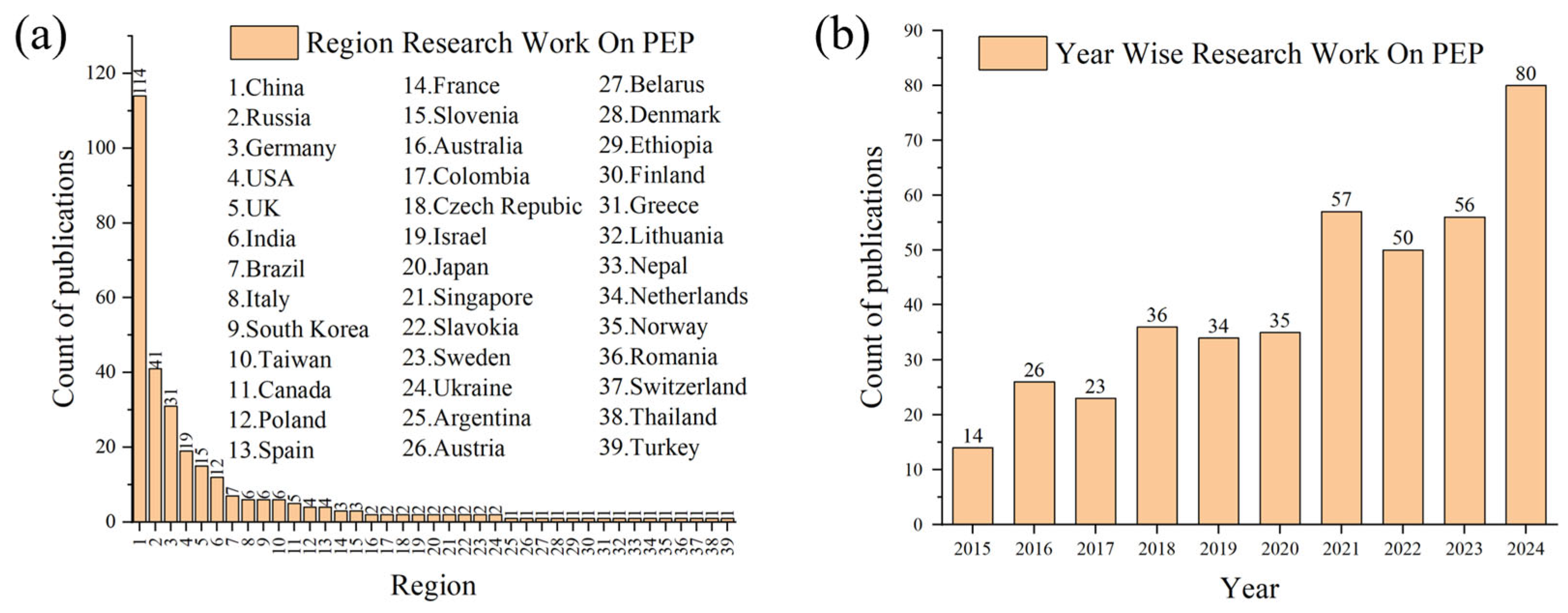
Figure 2 illustrates the regional distribution and decade-long trend of SCI-indexed publications on plasma electrolytic polishing. As depicted, research efforts on PEP are mainly concentrated in China, Russia, and several other nations. In general, the volume of related studies has exhibited a significant growth trend over the last ten years. This paper discusses the essential features and basic principles of plasma electrolytic polishing, providing a deeper understanding of its underlying mechanism. It investigates the effects of various factors, such as voltage, electrolyte composition, temperature, and polishing duration, on the performance of PEP when applied to both alloys and non-metallic mate rials. The application of PEP to materials including stainless steel, aluminum alloys, and hard alloys is examined, along with a brief overview of its use in coating removal. Finally, the article summarizes the current processes, mechanisms, and main applications of PEP while highlighting future opportunities and challenges in this field.

2. Mechanism of Plasma Electrolytic Polishing

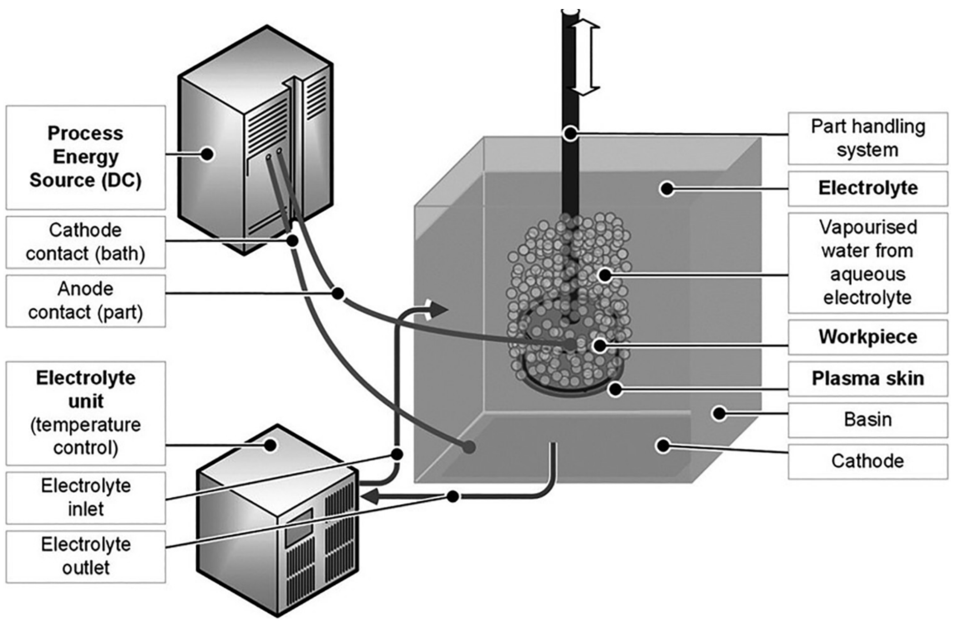
Plasma electrolytic polishing shares similarities with conventional electrolytic polishing. As shown in Figure 3 [10], a standard PEP setup consists of a tank containing the polishing solution, a power supply to provide the required energy, and a workpiece submerged in the electrolyte, serving as the anode. During the PEP process, both plasma and electrochemical reactions take place, leading to a series of physical and chemical changes in the workpiece and the surrounding solution [11]. The key factors influencing the polishing outcome include the applied voltage, the composition and temperature of the electrolyte, and the polishing duration. From the point of view of process diagnosis and control, the equipment can be regarded as a “power supply-electrolyser-electrode surface” of the total set of parameters of the system, thus laying the foundation for an in-depth understanding of the plasma electrolysis process in the system [12].

2.1. Advantages and Disadvantages of PEP

Plasma electrolytic polishing is a surface treatment technology that integrates the principles of electrochemistry and plasma physics, providing superior surface quality compared with conventional polishing methods. PEP is capable of producing ultra-smooth surfaces with extremely low roughness, typically below 0.1 μm, which is particularly advantageous for components requiring high precision and enhanced functional performance. The process effectively removes surface defects such as scratches, micro-protrusions, and incompletely sintered particles, thereby yielding defect-free surfaces with improved wear resistance, corrosion resistance, and fatigue life. Another significant advantage of PEP lies in its environmental compatibility. Unlike chemical polishing, which usually relies on strong acids and generates hazardous waste, PEP operates in salt-based electrolytes that are less harmful and more sustainable. This feature positions PEP as an environmentally friendly alternative, consistent with the growing demand for green manufacturing processes. In addition, PEP demonstrates high polishing efficiency and rapid processing speed, making it suitable for industrial applications where productivity is a critical factor. The technique is also highly effective for polishing components with complex geometries and additively manufactured parts.
Despite these notable advantages, several limitations hinder the widespread industrial application of PEP. First, it is primarily applied to metallic materials such as stainless steel, aluminum, titanium, copper, and their alloys, while examples of its use on non-metallic materials remain scarce, restricting its versatility. Second, the process is highly sensitive to operational parameters, including voltage, electrolyte concentration, and temperature. Improper control of these variables may result in unstable discharge behavior, uneven polishing, or even localized corrosion. Another drawback is the gradual degradation of the electrolyte. During polishing, metal ions dissolve from the workpiece, and together with gas evolution and by-product accumulation, they alter the electrolyte composition and reduce process efficiency. From a practical standpoint, PEP also requires relatively high-voltage power supplies, typically in the range of 200–400 V, which increases equipment costs and energy consumption compared with certain conventional alternatives.
In summary, PEP represents a surface treatment technology with considerable potential, especially for applications demanding high surface integrity and sustainability. Addressing its current shortcomings through deeper theoretical research and optimized process control will be essential to fully realize its industrial value.

2.2. Voltage-Current Characteristics of PEP

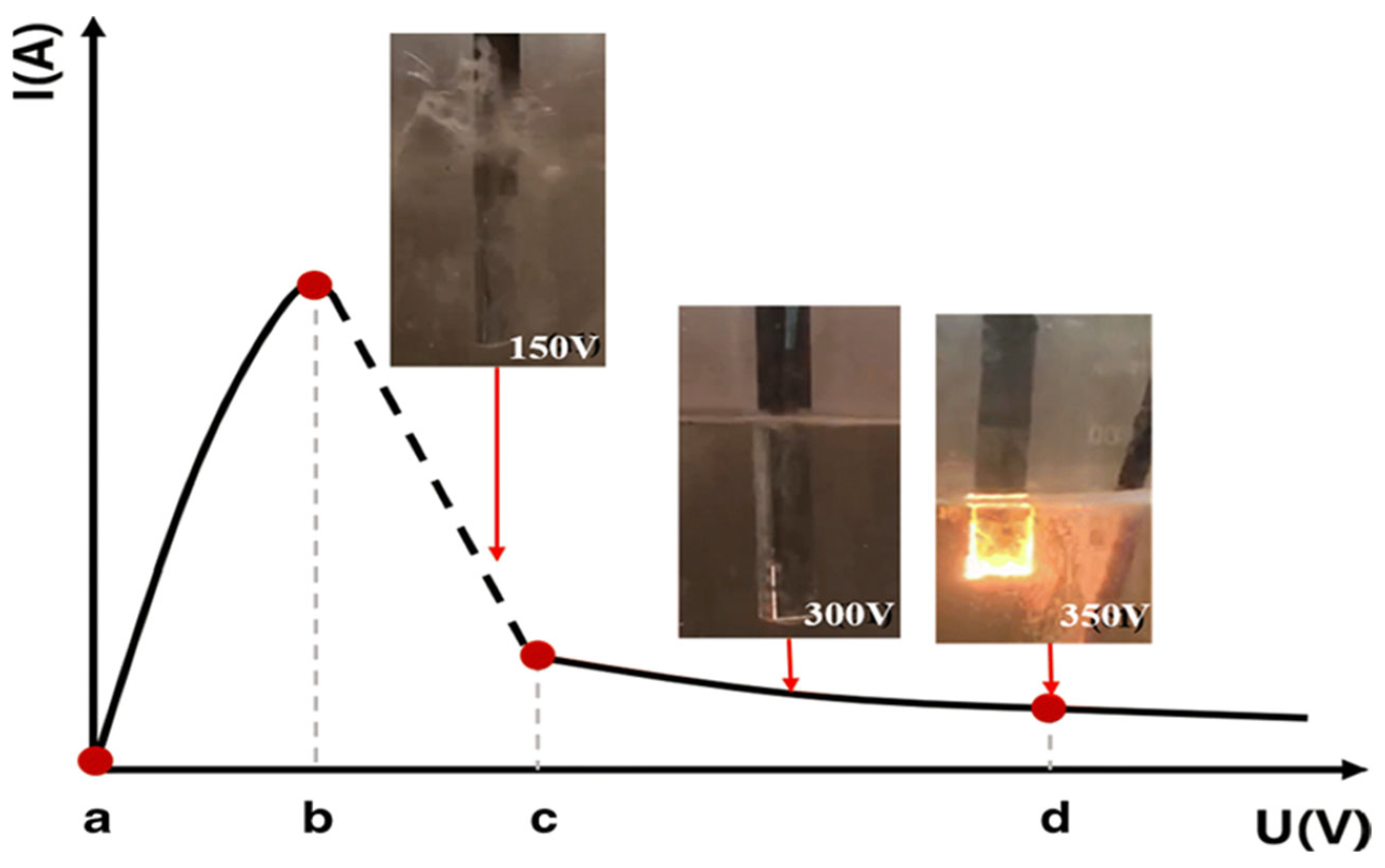
The voltage-current curve of PEP can be roughly divided into three parts: conventional electrolysis zone, transition zone and plasma discharge zone. In the conventional electrolysis region (voltage below 50 V), the current increases almost linearly with voltage, and only electrochemical dissolution occurs-no polishing taking place. In the transition region (approximately 50–150 V), the current growth slows or slightly decreases as an unstable vapor film begins to form on the workpiece surface. In the plasma discharge region (approximately 100–400 V), the current shows a sharp initial decrease, then stabilizes. This behavior indicates the formation of a stable vapor film around the workpiece and enables effective polishing. Kalenchukova et al. [13] found that during PEP on 304 stainless steels, the voltage–current curve follows the aforementioned trend. Notably, the current remains relatively low during the polishing stage, which accounts for the minimal heat generation and prevents significant temperature rise in the workpiece throughout the PEP process. The voltage-current curve under a typical PEP process is shown in Figure 4.
In the low-voltage region (a–b stage), voltage and current exhibit a positive linear relationship, following Ohm’s and Faraday’s laws. This stage corresponds to a typical electrolysis process, accompanied by hydrogen evolution, during which the electrolyte behaves as a stable resistor. When the voltage reaches point b, luminous gas appears periodically around the anode workpiece. These discharges adhere to the anode surface and exhibit continuous oscillatory behavior. Yerokhin A. L. et al. [14,15,16] attributed this phenomenon to electrolyte evaporation near the electrode caused by Joule heating. The color of the luminescent gas depends on the properties of the metal ions present in the electrolyte. During b–c stage, polishing takes place on the surface of the anode workpiece; however, the process remains unstable and is prone to interruption. When the voltage increases to point c, a continuous plasma vapor envelope forms around the anode, accompanied by a significant decrease in current. At this stage, the vapor envelope becomes stable. After point c, the plasma within the vapor envelope stabilizes, enabling a controlled and consistent surface treatment process [13]. This stage marks the beginning of stable PEP. However, studies by Mazza et al. [17,18] indicated that the position of point c is not fixed, which depends on factors such as the electrode shape and size, as well as the composition and concentration of the electrolyte. When the voltage exceeds point d, polishing can still occur; however, strong arcing appears, and the electrolyte becomes unstable. The intense electric arc generated at high voltage causes the electrolyte to boil, leading to the formation of a thicker vapor envelope that interferes with the continuation of the polishing process. Therefore, effective polishing is typically carried out within the c–d region. Based on the voltage-current characteristics of PEP, the appropriate polishing stage for metal materials can be preliminarily identified.

2.3. PEP Discharge Mechanism

During the PEP process [19], the workpiece, which serves as the anode, is immersed in a polishing solution within an electrolytic bath, with the bath functioning as the cathode. A voltage ranging from 100 to 400 V is applied. Polishing is typically completed within 10 min; however, ultra-precision polishing may require up to 30 min. The process concludes with the shutdown of power, followed by ultrasonic cleaning and other post-treatment procedures. According to the thermodynamic model of vapor envelope formation (1): In plasma electrolytic polishing of stainless steel, bubble nucleation depends mainly on solution surface tension and localized superheating. Although electrolyte concentration remains relatively stable and has little effect on surface tension, micro-convex regions on the surface concentrate charge and ohmic heating, reaching the superheat threshold more easily. Thus, bubbles preferentially form and grow at bulges, then coalesce and detach from the anode surface [20].
Δ T s = T s i 1 g ρ g 16 Π σ 1 3 3 κ T g ln κ T g n ( R c ) v b g h p
Due to the high voltage in PEP, a distinctive vapor envelope (VGE) forms between the anode workpiece and the electrolyte [21]. This non-conductive vapor envelope, primarily composed of water vapor and vaporized electrolyte [22,23], exhibits the highest resistance in the circuit. Consequently, a high potential difference arises across the vapor envelope, at the interfaces with the electrolyte and the workpiece. Under the electric field, localized regions of the vapor envelope are broken down, generating plasma discharge and forming discharge channels. In these channels, plasma discharge initiates complex physicochemical reactions between the metal surface and the vapor envelope, resulting in the formation and removal of oxides and other pollutants. Polishing is achieved when the material removal rate surpasses the oxidation rate. It is generally believed that the polishing effect results from the combined actions of the anodic electric field, as well as the interactions of electrons and ions within the vapor envelope.
Currently, there are several process models for the PEP process. Zakharov, S.V. et al. [24] proposed an ionization model for PEP: Ionization Model of the EPI Process. The primary ionization mechanism in plasma electrolytic polishing is ion–electron emission, with the ions originating from the components of the electrolyte solution. The initiation of the plasma process depends on the concentration, activity, and mass of the solute molecules, and can therefore occur under different temperature and processing conditions. When the electrolyte bridge comes into contact with the anode surface, anions accelerated by the electric field gain sufficient energy (approximately 10 eV) to collide with the anode. Upon impact, these anions interact with the surface, inducing electron emission. This occurs through Auger neutralization, wherein the bombarding ion possesses an unoccupied energy level below the Fermi level of the target metal. In this process, an electron from the conduction band of the metal fills the vacant state, neutralizing the ion. The neutralization releases energy, which is subsequently transferred to another conduction electron, enabling it to overcome the work function and escape from the metal surface.
The flow injection theory [25] provides an effective explanation for the microscopic mechanism of surface material removal by plasma discharge. This process is illustrated in Figure 5. At the beginning of the polishing process, when the anode workpiece comes into contact with the electrolyte, electrolysis occurs, generating a certain amount of electrons and positive ions. Under the influence of the electric field, electrons move rapidly toward the anode, with a velocity significantly higher than that of the positive ions [26]. As electrons pass through the vapor envelope, the comparatively slower-moving positive ions are left behind, forming a space charge within the vapor envelope, as shown in Figure 5a. During the rapid movement of electrons, they will collide with neutral particles, generating new electrons and positive ions, which causes an avalanche of electrons in the vapor envelope and forms an electron avalanche. In this process, electrons are located at the leading edge of the avalanche front, while the positive ions, which are nearly stationary by comparison, remain at the trailing end, as shown in Figure 5b. Due to the presence of electron avalanches, surrounding photons excite neutral particles, leading to the generation of secondary electrons. Under the influence of the electric field, these secondary electrons initiate additional, smaller electron avalanches. As the number of these avalanches increases, they cause local distortions in the electric field. The smaller avalanches are attracted to the leading edge of the primary electron avalanche and eventually merge, forming the initial discharge channel, as shown in Figure 5d, which gradually extends across the entire vapor envelope. Within this discharge channel, a large number of high-speed electrons move rapidly toward the anode, bombarding the surface of the workpiece. This bombardment causes localized impact and rapid melting of the surface metal, as illustrated in Figure 5f. In addition, the reverse motion and collision of charged particles in the discharge channel release thermal energy, causing rapid heating and expansion. Meanwhile, the induced current generates a centripetal contraction effect [27], thinning the channel. Their interaction triggers a gas explosion, leading to local melting, metal removal, and eventual channel collapse.
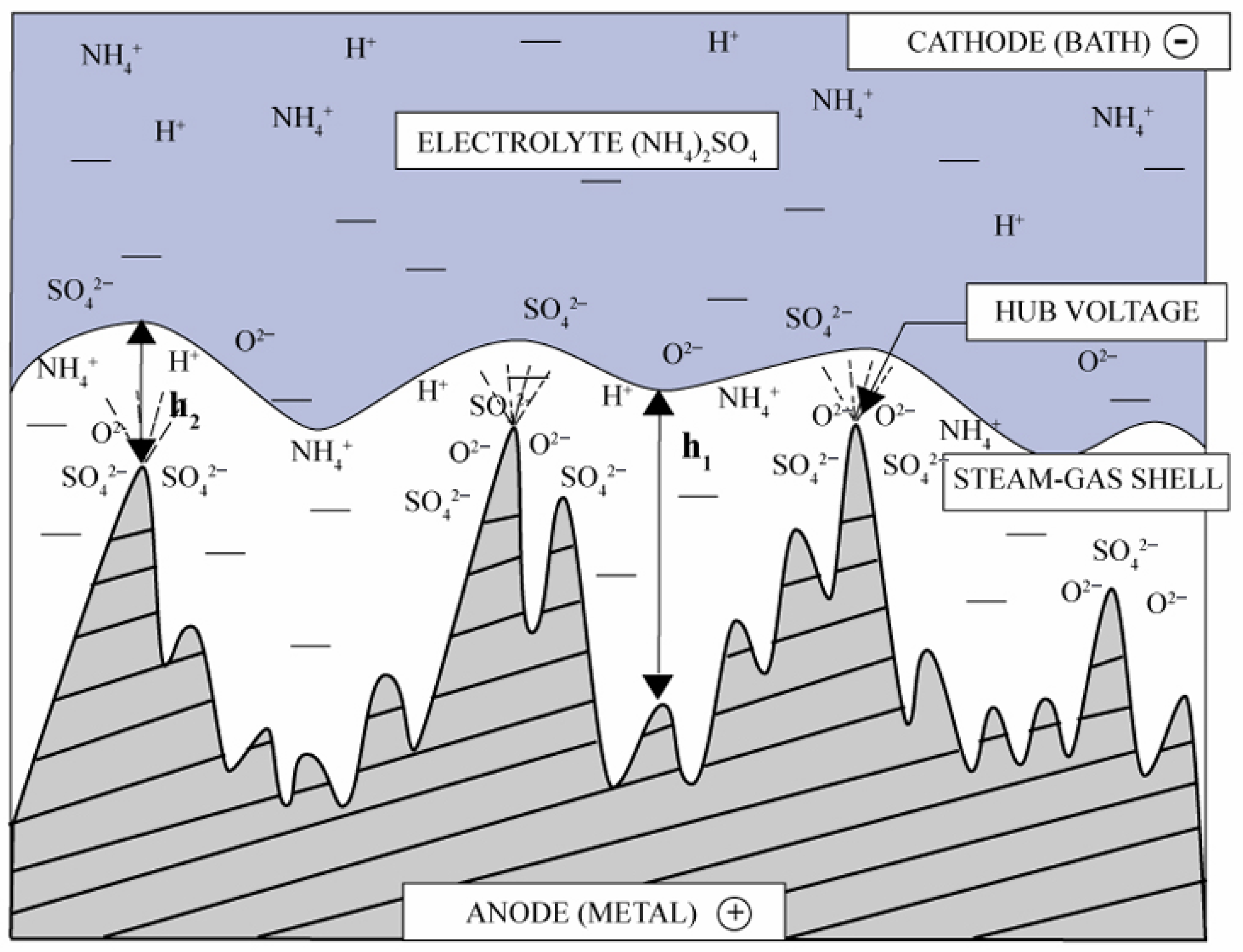
As shown in Figure 6, during PEP process, plasma discharge preferentially occurs at the microscopic protrusions on the workpiece surface. This phenomenon is attributed to the higher electric field intensity around the convex features (h2) compared to the concave regions (h1). In these raised areas, the vapor envelope is thinner, allowing for higher current density and more rapid electron transfer to the anode surface [28,29]. This facilitates the accumulation of space charge, leading to distortion of the local electric field and the formation of discharge channels. Additionally, discharge tends to occur on the anodic surface of the metal, where localized melting induces micro-explosions, ultimately leading to the collapse of the discharge channels [27]. Since recessed regions experience weaker fields, material is mainly removed from protrusions, gradually smoothing the surface. Even if a channel collapses prematurely, repeated discharges occur at the same site as the vapor layer continuously forms and collapses [30]. Zeidler et al. [31] suggested that plasma electrolysis and electrochemical reactions act simultaneously, subjecting the surface to combined electrochemical, thermophysical, plasma-chemical, and hydrodynamic effects [32,33], which together dissolve and impact unevenness on materials surface to achieve polishing.
Beyond the above mechanism, Gupta [34] proposed that bubble generation and collapse contribute to removing micro-bumps from metal surfaces. Under stable plasma conditions, a vapor envelope forms around the workpiece. High voltage drives anions toward gas bubbles near the anode, where they accumulate and create a localized electric field. Once this field exceeds a threshold, the gas ionizes and initiates plasma discharge. The resulting plasma can reach 6000–7000 K [35]. Contact between hot plasma bubbles and the cooler electrolyte causes bubble implosion, releasing shock waves. This process, similar to cavitation, generates pressures of several hundred MPa [36], effectively removing surface protrusions. Bubble collapse also accelerates anion deposition, forming a loose oxide layer that can be easily removed. Although many studies have examined PEP mechanisms, most focus on the vapor envelope, underscoring its critical role in the process.

3. Plasma Electrolytic Polishing Process

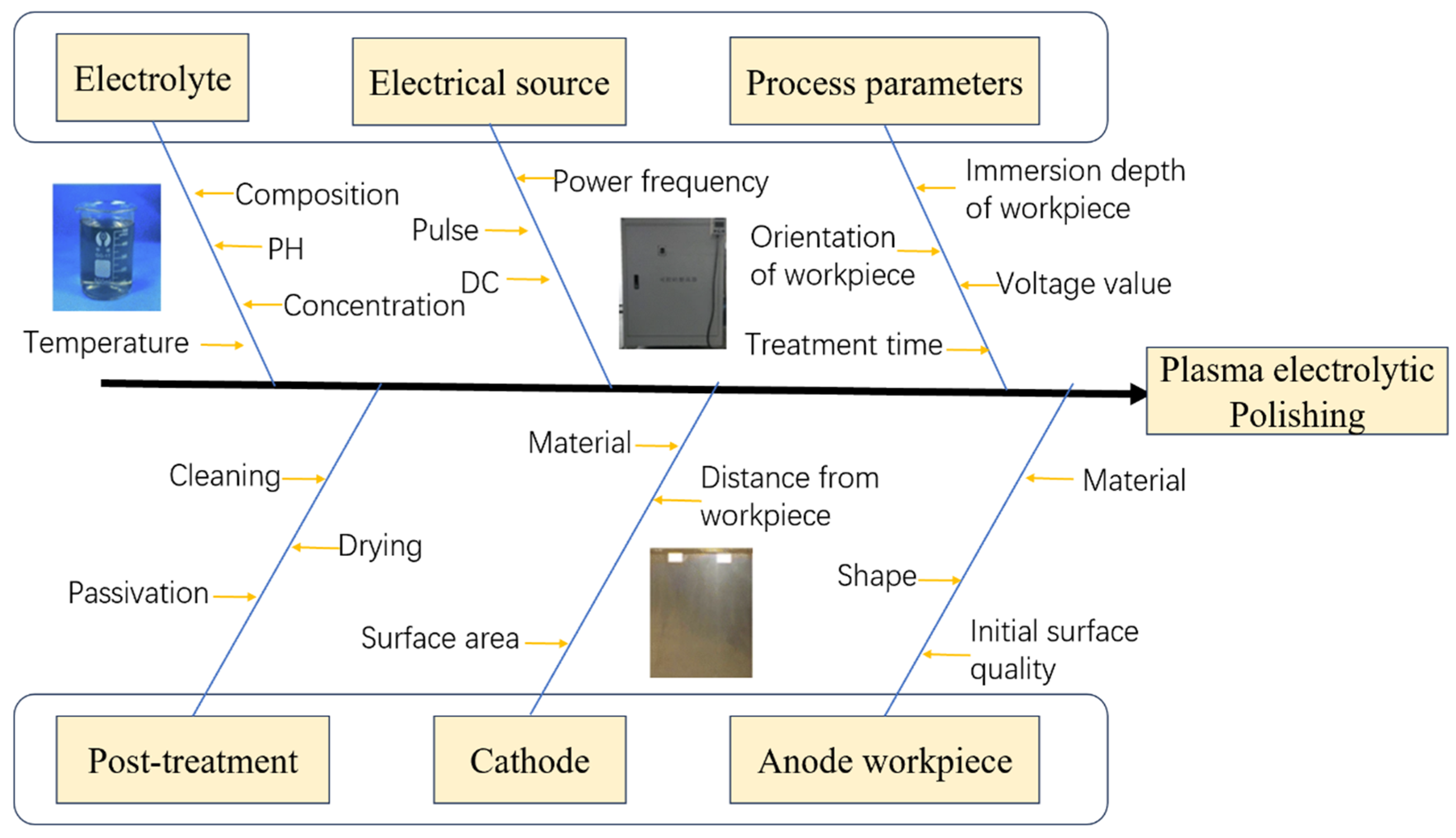
In plasma electrolytic polishing, the quality of the polished surface and the efficiency of material removal are primarily determined by a wide range of interrelated parameters. These include the electrolyte’s concentration and temperature, the applied power supply voltage, the polishing duration, the nature of pre- and post-treatment steps, the type and configuration of the cathode, as well as the intrinsic physical and chemical properties of the workpiece material itself, as illustrated in Figure 7. These factors do not act in isolation but rather interact simultaneously, exerting a collective influence on the ultimate polishing performance. Because of the considerable complexity and the inherent difficulty in accurately controlling so many variables, most research efforts tend to identify the most critical influencing factors and then refine the polishing process by carefully adjusting these selected parameters. From a mechanistic perspective, plasma discharge characteristics and the state of the vapor envelope remain central to the polishing outcome. The applied voltage delivers the necessary energy input, governing both the stability of the vapor envelope and the dynamics of charged particles within it. Meanwhile, the envelope’s thickness is closely associated with electrolyte temperature and immersion depth [37], whereas polishing time directly dictates the surface finish achieved. Taken together, these interconnected parameters play a decisive role in shaping the effectiveness of PEP.

3.1. Supply Voltage

The power supply voltage plays a critical role in determining the surface polishing quality of the workpiece. Wang [38] investigated the PEP on 304 stainless steels, with particular focus on the effect of voltage on surface roughness and material removal rate (MRR). The results showed that at a constant voltage, the MRR remained nearly stable, indicating consistent polishing conditions. However, when the voltage was varied, the MRR initially increased and then decreased, reaching its peak around 220 V. Within the 220–250 V range, the MRR was at its highest, while further increases in voltage led to a decline in removal efficiency. According to the heat balance equation, higher voltages accelerate the heating of the electrolyte to its vaporization temperature, resulting in the formation of a thicker vapor envelope around the workpiece. This condition promotes spark discharges rather than stable plasma, ultimately reducing the MRR. Gradually reducing the voltage leads to a thinner vapor envelope, which becomes easier to penetrate, thereby increasing the material removal rate (MRR). However, if the voltage is reduced excessively, a stable vapor envelope cannot form. In such cases, the workpiece undergoes direct dissolution in the electrolyte, leading to the formation of an oxide layer and a subsequent decline in the polishing performance [39,40].
Generally, the voltage applied in PEP ranges from 100 to 400 V. However, the specific voltage selected depends on the type of metal being treated. For example, stainless steel is typically polished at voltages between 220 and 300 V, titanium alloys at 280–400 V, and aluminum alloys at 150–250 V. These differences can be attributed to the varying thermophysical properties of the materials. Titanium alloys, with a high melting point of approximately 1660 °C and low thermal conductivity, require higher voltages to sustain stable plasma discharge. In contrast, aluminum alloys have a much lower melting point (around 660 °C) and exhibit excellent thermal conductivity, allowing effective polishing at lower voltages. Therefore, aluminum alloys can be polished at relatively low voltages. However, if the voltage exceeds a certain threshold, it may lead to the formation of molten pits on the surface. In addition, the characteristics of the metal’s surface oxide layer also influence the selection of polishing voltage. For example, the surface of titanium alloys is covered with a dense TiO2 oxide film that possesses high insulating properties, requiring a breakdown voltage exceeding 300 V to initiate effective polishing. In contrast, the Cr2O3 oxide film on stainless steel is thinner, and the Al2O3 film on aluminum alloys is hard and porous. As a result, the polishing voltage required for stainless steel and aluminum alloys is generally lower than that for titanium alloys.
As PEP typically utilizes low-concentration salt solutions, the cost of solutes is relatively low. Therefore, the primary operational cost arises from power consumption. To minimize energy usage, a two-stage polishing process is often employed: an initial high-voltage stage followed by a lower-voltage stage. This approach not only reduces overall energy consumption but also enhances the polishing quality. Furthermore, Cao [41] proposed a high-frequency pulsed power supply PEP process specifically for amorphous alloys, which significantly improved the surface finish of the treated workpieces. High-frequency pulsed power regulates the discharge process and influences the stability of the vapor envelope. The pulsed effect also promotes electrolyte circulation, enhances processing efficiency, and improves overall polishing performance. Table 3 is a comparison of continuous power and pulsed power in PEP. Yerokhin et al. [42] found that applying pulsed current within a specific frequency range not only reduces energy consumption but also significantly improves surface finish. Experimental results further confirm that optimal polishing performance can be achieved at a higher frequency (f = 10 kHz). It is worth emphasizing that the selection of polishing voltage is a critical factor in determining the success of the PEP process. Within a certain range, the material removal rate may decrease with increasing voltage, and both excessively high and excessively low voltages can negatively affect the polishing outcome. Therefore, it is essential to select an appropriate voltage based on the specific material properties in order to achieve optimal polishing performance while minimizing energy consumption.

3.2. Electrolyte

The influence of electrolyte on PEP is more complicated. Generally, the composition, temperature, and concentration of the electrolyte significantly influence the final polishing outcome. Therefore, it is crucial to select an appropriate electrolyte tailored to the specific metal being polished. For instance, a low-concentration ammonium sulfate solution is suitable for polishing austenitic stainless steel; however, it is unsuitable for carbon steel, as it reacts with the carbon steel matrix to form iron sulfate on the surface, causing etching [43]. Studies have shown that adding components such as polyols or surfactants to the base electrolyte can modify its surface tension, viscosity, and conductivity. These changes influence the formation, composition, and stability of the vapor envelope, thereby enhancing the polishing performance [40]. Consequently, the electrolyte composition plays a direct and critical role in determining the stability and efficiency of the PEP process.
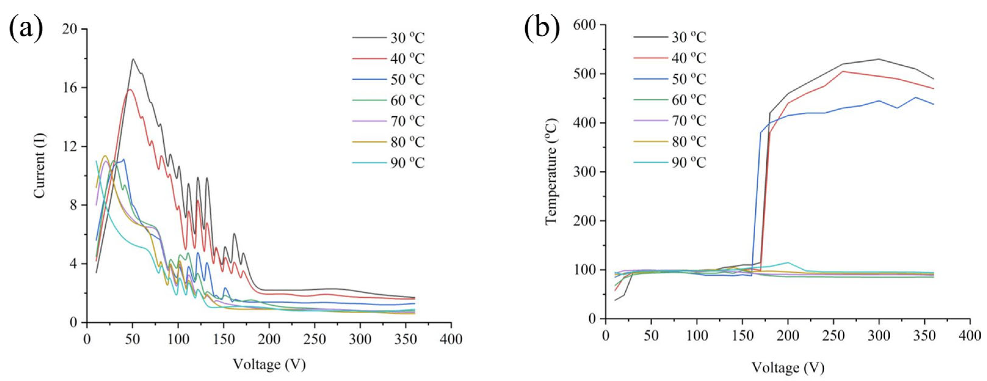
The electrolyte temperature can also change the physical properties of the solution and affect the state of the vapor envelope. Stabilizing electrolyte temperature within a specific range is essential for obtaining a high-quality polished surface. Kusmanov et al. [44] studied the relationship between anode workpiece surface temperature, electrolyte temperature, current, and power supply voltage in a 5% ammonium sulfate electrolyte (Figure 8). They found that once the voltage increased beyond a certain threshold, and the electrolyte temperature exceeded 50 °C, the surface temperature of the anode workpiece remained nearly stable. Conversely, the workpiece surface temperature increased rapidly with voltage at temperatures between 30 °C and 50 °C. This indicates that only below 50 °C does increasing voltage lead to current interruption, achieving steady-state anode heating and enabling stable vapor envelope formation. In a study on the PEP of mild steel using a 2.5% NH4Cl solution [45], increasing the solution temperature from 40 °C to 90 °C resulted in a nearly fivefold reduction in the MRR of the workpiece surface. Wang et al. [46] employed an orthogonal experimental design to systematically evaluate the effects of electrolyte concentration, temperature, immersion depth, and spatial orientation on the surface roughness of the workpiece. Analysis of 16 experimental groups revealed that electrolyte concentration and temperature had the most significant influence on surface roughness, followed by immersion depth and spatial orientation. These results indicate that electrolyte temperature is one of the key factors affecting polishing quality. Notably, the lowest surface roughness was achieved when polishing at 80 °C.
Electrolyte concentration influences the conductivity of the vapor envelope, the heat flux within the system, and the electrochemical reactions occurring at the anode surface. Wang et al. [46] found that the surface roughness of polished stainless steel decreases with increasing electrolyte concentration within a certain range, it can be reduced from 0.5 μm to as low as 0.194 μm, which is significantly lower than the initial roughness. However, when austenitic stainless steel is polished using ammonium sulfate solutions of varying concentrations, the highest surface finish is achieved at lower concentrations. Despite this improvement, the process tends to be unstable. In contrast, excessively high concentrations lead to an increase in surface roughness [47]. Therefore, electrolyte concentration serves as a critical parameter in determining polishing quality, and must be carefully optimized based on the specific characteristics of the workpiece material.
The reasonable selection of electrolyte composition, temperature, and concentration is critical to achieving high-quality surface finishes in PEP. Firstly, the electrolyte composition directly determines the success of the polishing process. If not properly selected, it may cause corrosion on the metal surface, leading to pit formation. Secondly, excessively high electrolyte temperatures can result in minimal temperature change on the workpiece surface, making it difficult to form a stable vapor envelope, thereby reducing the polishing efficiency. Lastly, the electrolyte concentration must be carefully controlled, if it is too high, it may increase the surface roughness of the metal after polishing.

3.3. Polishing Time

Polishing time has a significant impact on the surface roughness of the workpiece. Rajupt [48] investigated the relationship between surface roughness and polishing time. The results showed that during the initial 0–5 min of polishing, the surface roughness gradually decreased. The reduction was rapid at first and then slowed over time, with the Ra value decreasing from approximately 0.3 to 0.1 μm. Nestler et al. [8] compared the surface roughness of copper alloys before and after polishing at different durations. The results indicate that, within a certain time range, increased polishing time leads to a smoother surface, as shown in Figure 9. The Ra of the copper alloy was reduced from 0.081 to 0.015 μm in 2 min with the increase in time.
Generally, the relationship between workpiece surface roughness and polishing time is nonlinear. During the initial stage of PEP, surface roughness decreases rapidly. As polishing continues, the rate of reduction gradually slows until it eventually reaches a plateau [49]. The relationship between the surface roughness Ra of the workpiece and the polishing time t can be expressed by the following equation:
Ra = Aexp(−t/τ) + C
where τ is the time constant and A and C are empirical parameters that take into account the polishing conditions and the physical properties of the workpiece. The reduction in surface roughness can be attributed to electrochemical reactions between the workpiece and the electrolyte. In the early stages of polishing, a large number of surface micro-protrusions are rapidly removed, leading to a significant improvement in surface smoothness. As polishing progresses and the surface becomes smoother, the rate of roughness reduction slows accordingly. Based on the discharge channel formation mechanism, the material removal rate also decreases during this stage. Studies have also shown that exceeding a certain polishing duration can lead to an increase in surface roughness. Vana et al. [50] studied surface finish and roughness evolution of austenitic stainless steel during PEP. It was observed that the surface finish improved rapidly at the initial stage, then gradually deteriorated over time. After 10 min, the surface condition had reverted to a state comparable to the original. This indicates that the polishing process increasingly concentrates material removal at the grain boundaries, resulting in the formation of a secondary surface relief and, consequently, an increase in surface roughness.
For different metals, polishing time must be carefully controlled to achieve optimal results. The reduction in surface roughness typically follows a trend of rapid initial improvement, followed by a slower decrease until a plateau is reached. From an energy efficiency perspective, prolonged polishing does not necessarily yield better outcomes. PEP can be considered complete once the MRR drops significantly.

4. The Application of Plasma Electrolytic Polishing in Various Alloys

Currently, plasma electrolytic polishing has been successfully applied to the surface finishing of various alloys, including steel, aluminum, titanium, copper, and hard alloys. It has also demonstrated effective surface treatment performance for metal components produced by additive manufacturing. Figure 10 shows the PEP results of some alloys, and Table 4 presents the selection of electrolytes and optimal parameter ranges for PEP of some materials.

4.1. Stainless Steel

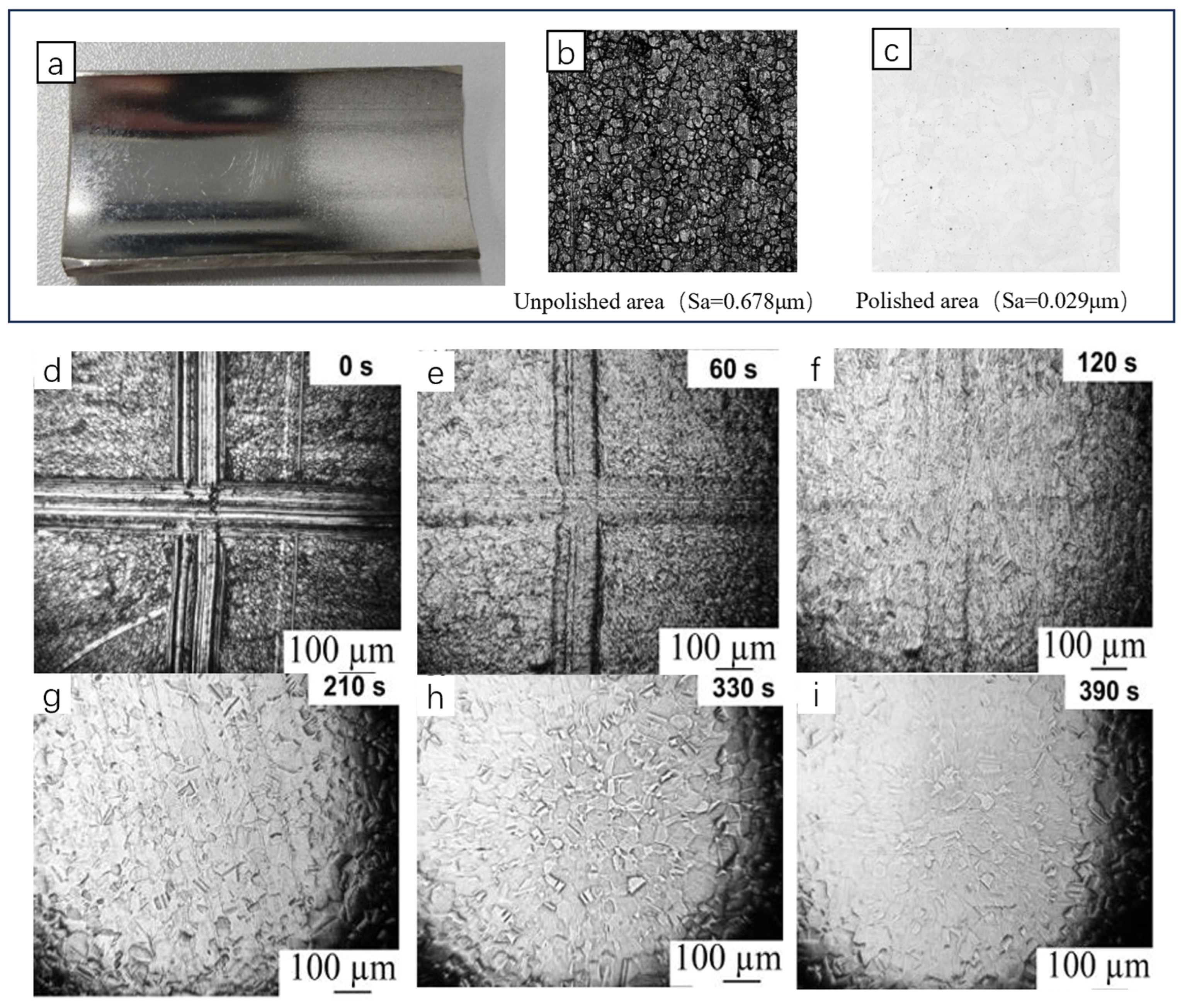
Most current studies on PEP focus on stainless steel. SS316L stainless steel is one of the predominant materials used in metal additive manufacturing, making its high-precision polishing a key area of research focus [53]. Wang et al. [46] proposed optimal parameters for PEP on stainless steel, including an electrolyte composed of 4–5 wt% (NH4)2SO4, a solution temperature of 80 °C, and a workpiece immersion depth of 5 mm. The surface quality achieved through polishing can be enhanced by increasing the applied voltage. Cornelissen [25] investigated the internal surface polishing of stainless steel pipes under varying voltage conditions. At 260–320 V, polished surface finish was significantly higher than unpolished surfaces. Figure 11a–c shows microscopic images of unpolished and polished surfaces, and Sa decreased from 0.678 μm to 0.029 μm. The electrolyte used in PEP of stainless steel is typically a low-concentration (NH4)2SO4 solution. However, the concentration should not be too low, as this may lead to process instability [47]. Mihal [54] investigated the influence of varying (NH4)2SO4 solution concentrations on the PEP performance of 304 stainless steel, and found that a 3 wt% solution produced the best polished surface after up to 390 s of treatment at temperatures above 60 °C. On Figure 11d–i the modification of surface of the workpiece is presented for different time values.
To obtain high-quality polished surfaces on stainless steel, Lukas [55] performed pre-PEP mechanical polishing (grinding, sandblasting) on SS316L. By combining these methods, the surface roughness was significantly reduced from 15.03 μm to 0.12 μm, indicating a substantial improvement in surface quality. Zeidler et al. [56] employed a combined process involving granular sandblasting, vibratory grinding, and PEP on stainless steel propellers. This integrated approach proved more efficient and resulted in superior surface quality compared to using each technique individually. Similarly, Loaldi [57] combined mechanical polishing with PEP for additively manufactured 316L stainless steel, demonstrating the potential to reduce surface roughness from Sa 9 μm, Ssk 0.4 μm to Sa 0.6 μm, Ssk 0.3 μm. Generally, suitable mechanical pre-polishing removes large surface asperities, thereby enhancing the effectiveness of subsequent electrochemical erosion. Table 5 summarizes several stainless steel PEP process parameters, electrolyte compositions, and corresponding polishing results.

4.2. Aluminum Alloys

Aluminum alloys are widely used in lightweight applications within the aerospace and automotive industries due to their excellent heat dissipation and mechanical properties [64,65]. Numerous studies have investigated the influence of electrolyte composition on the PEP of aluminum and its alloys. Table 6 demonstrates the PEP process parameters and effects for several aluminum alloys.
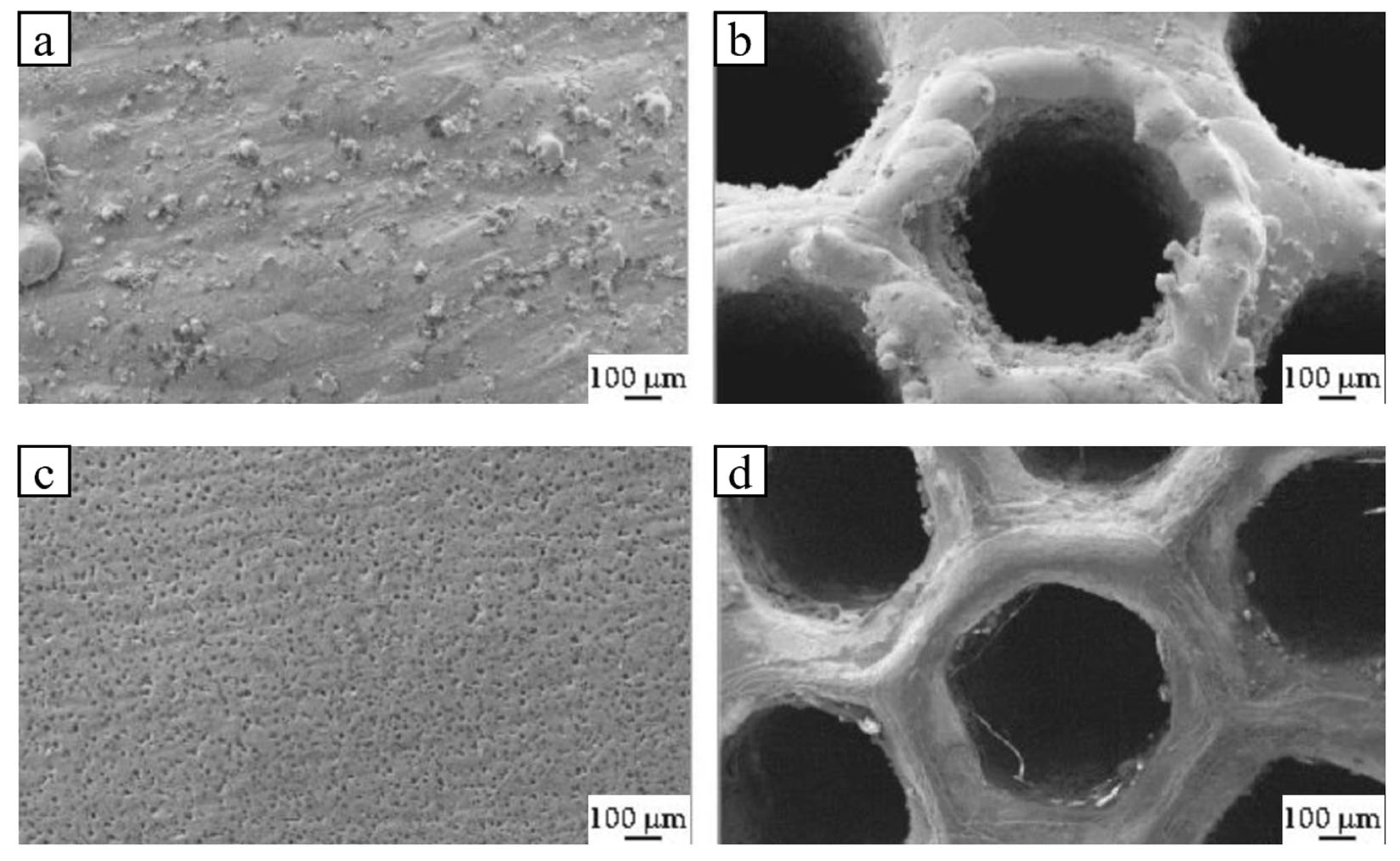
Smirnov [66] prepared an electrolyte by dissolving 4% KCl and 2% C2H2O2 in water. After 2 min of PEP of the AlSi10Mg alloy, the surface roughness was reduced significantly from an initial 12.4 μm to 1.6 μm. Duradji et al. [67] formulated an electrolyte consisting of 10% NH4Cl, 4% KCl, and 3% H2C2O4 for aluminum polishing, which achieved optimal results. Specifically, the surface roughness decreases with the extension of polishing time, dropping from 0.63 μm to a minimum Ra value of 0.015 μm. Gaysin et al. [68] applied PEP to aluminum alloy surfaces produced by direct metal laser sintering of the Al-Si-Mg system. Using a 7% NaCl aqueous solution, the roughness Rz was reduced from 5.443 μm to 3.277 μm. The microscopic morphology of the material surface before and after PEP treatment is shown in Figure 12. The incompletely sintered metal granule residues were eliminated after polishing, resulting in a smoother surface free of micro-protrusions. Zakharov [69] investigated the influence of electrolyte composition on the PEP process of D16 aluminum alloys. The study revealed that effective polishing occurred only in nitrate-based electrolytes. Optimal polishing conditions were established at a voltage of 280–320 V, a polishing duration of 2 min, and an electrolyte consisting of 4–5% KNO3, 2–3% C6H8O7, and 0.5–1% C3H8O3. Under these conditions, the surface roughness of the aluminum alloy was reduced from 1.1 μm to 0.2 μm.
Wang et al. [64] investigated the influence of various polishing parameters on the surface roughness of 6061 aluminum alloy. They found that the minimum roughness value of 0.138 μm was achieved under the conditions of a supply voltage of 370 V, electrolyte temperature of 80 °C, processing time of 4 min, and workpiece immersion depth of 16 cm. The study showed that the polishing time has the greatest influence on the polishing effect. Kui [70] used an optimized electrolyte formulation to polish 5052 aluminum alloy at a processing temperature of 80 °C for 1 min. This treatment successfully reduced the surface roughness of the alloy from 5.4 to 1.6 μm, significantly improving its surface finish.

4.3. Titanium Alloy

Titanium alloy materials, characterized by high specific strength, excellent specific stiffness, superior mechanical properties, outstanding biocompatibility, and strong corrosion resistance, are widely used in both the biomedical field and aerospace industry [71,72]. Navickaitė et al. [73] applied PEP to TC4 alloy and observed that the surface roughness plateaued after 32 min of polishing, with a surface roughness decreased from 21.6 μm to 1.0 μm. Additionally, they investigated a combined method involving powder spraying and PEP, which further reduced Ra to 0.6 μm. Notably, the combined treatment achieved surface quality comparable to that of longer conventional PEP processes. Bernhardt [74] aimed to produce biocompatible titanium surfaces by combining sandblasting, vibration, and PEP on TC4 alloy. The workpieces were immersed in a 2–5% aqueous ammonium sulfate solution at 93 °C. The resulting surface achieved Ra below 0.5 μm, meeting medical standards and exhibiting good surface wettability with a contact angle of 66.9°. SEM images and surface morphology of titanium alloy at different polishing stages are shown in Figure 13.
Although polishing parameters may vary, fluoride-based electrolytes are commonly used. This is because titanium alloys tend to form a dense oxide layer on their surface during polishing. To effectively remove this layer, researchers typically use fluoride salts, as the HF generated in their aqueous solution helps break down the oxide layer. Alekseev et al. [53] aimed to eliminate surface scratches and achieve high-quality polishing of titanium alloys. They used a 90 °C ammonium fluoride solution as the electrolyte to polish BT6 titanium alloy at 300 V for 6 min. This process yielded surfaces with high smoothness (Ra < 0.1 μm), meeting requirements for medical and aerospace applications. The optimized PEP parameters and corresponding results for titanium alloys are summarized in Table 7.
Parfenov [77] systematically investigated the effect of different fluoride salts on PEP of titanium alloys. Smyslov et al. [78] founded that NH4F reacts with the surface layer of titanium to form titanium tetrafluoride, which is subsequently removed during the PEP process, thereby reducing surface roughness. Beck [79] also investigated the use of a phosphoric acid electrolyte for PEP of titanium. When treated at 150 V and 20 °C for 3 min, the process resulted in the formation of a ceramic-like nanoporous oxide layer on the surface. In summary, PEP of titanium alloys leads to the formation of an oxide film and localized surface melting due to the instantaneous high temperatures generated during the process. This simultaneously enhances both the corrosion resistance and surface smoothness of the titanium alloy.

4.4. Copper Alloys

Copper and its alloys are widely used in industry because of their excellent thermal and electrical conductivity. PEP not only removes the oxide layer on the surface of copper alloys, but also significantly improves their corrosion resistance [80]. The PEP process parameters and corresponding effects for various copper alloys are summarized in Table 8.
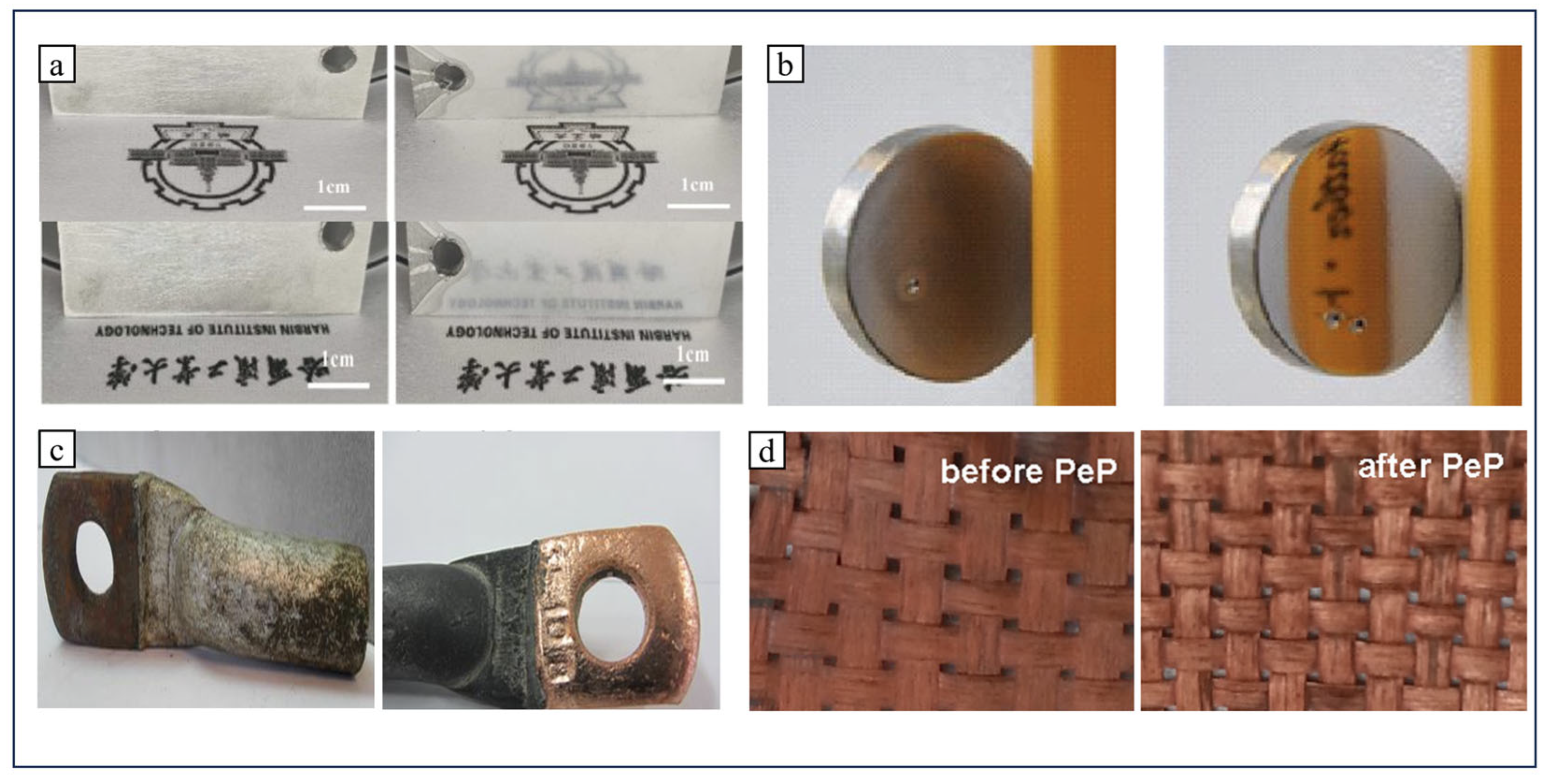
Nestler et al. [8] studied the application of PEP on copper and copper alloys, and explored the effect of electrolyte composition (Containing C4H6O6) on the quality of the polished surface. Valiev et al. [83] conducted PEP of copper alloys using an applied voltage range of 55 V to 400 V, with NaCl, C6H8O7, and NH4NO3 serving as the electrolyte components. The roughness Ra could be reduced to 0.16 μm–0.08 μm. Huang [83] studied PEP on H62 brass, and proposed that the optimal process parameters included a solution temperature of 80 °C, a processing time of 5 min, an immersion depth of 5 cm, and an electrolyte concentration of 4%. Under these conditions, the surface roughness of brass was reduced from 0.683 μm to 0.176 μm. In the PEP of L63 brass, aqueous ammonium salts are usually chosen as the electrolyte, such as NH4Cl, C6H17N3O7, and the surface of the processed brass exhibited a mirror-like luster, with its cleanliness level increasing from 9 to between 11 and 12 [81,84]. Böttger et al. [85] applied PEP for the pretreatment of metallized fibers with the aim of replacing flux in the large-scale production of CFRP polymers. They investigated the effects of PEP on pure copper foils and copper-plated carbon fiber fabrics. The results showed that PEP completely removed the corrosion layer from the copper sheet, significantly enhancing its gloss. The copper-plated fabric surface also became more glossy. Zhang [86] determined the optimal PEP process parameters through orthogonal experiments as follows: a voltage of 260 V, solution temperature of 90 °C, polishing time of 11 min, and immersion depth of 16 cm. Under these conditions, the sample achieved the lowest surface roughness of 0.064 μm (initial roughness 0.834 μm). The surface morphology of copper before and after polishing is as shown in Figure 14.

4.5. Cemented Carbide

Cemented carbide is widely used in the field of cutting tools, molds and wear-resistant parts because of its high hardness and corrosion resistance [87]. It is usually made of high-hardness carbide combined with metal binders such as Co, Ni, and Fe through powder metallurgy, including WC-Co type alloys, WC-TiC-Co type alloys and cobalt-chromium alloys. However, these alloys exhibit poor wear resistance and therefore require a hard coating before being used as tools. To ensure strong adhesion between the coating and substrate, thorough surface cleaning is essential [88]. PEP offers an efficient and environmentally friendly cleaning method. The process parameters and effects of PEP on carbide are given in Table 9.
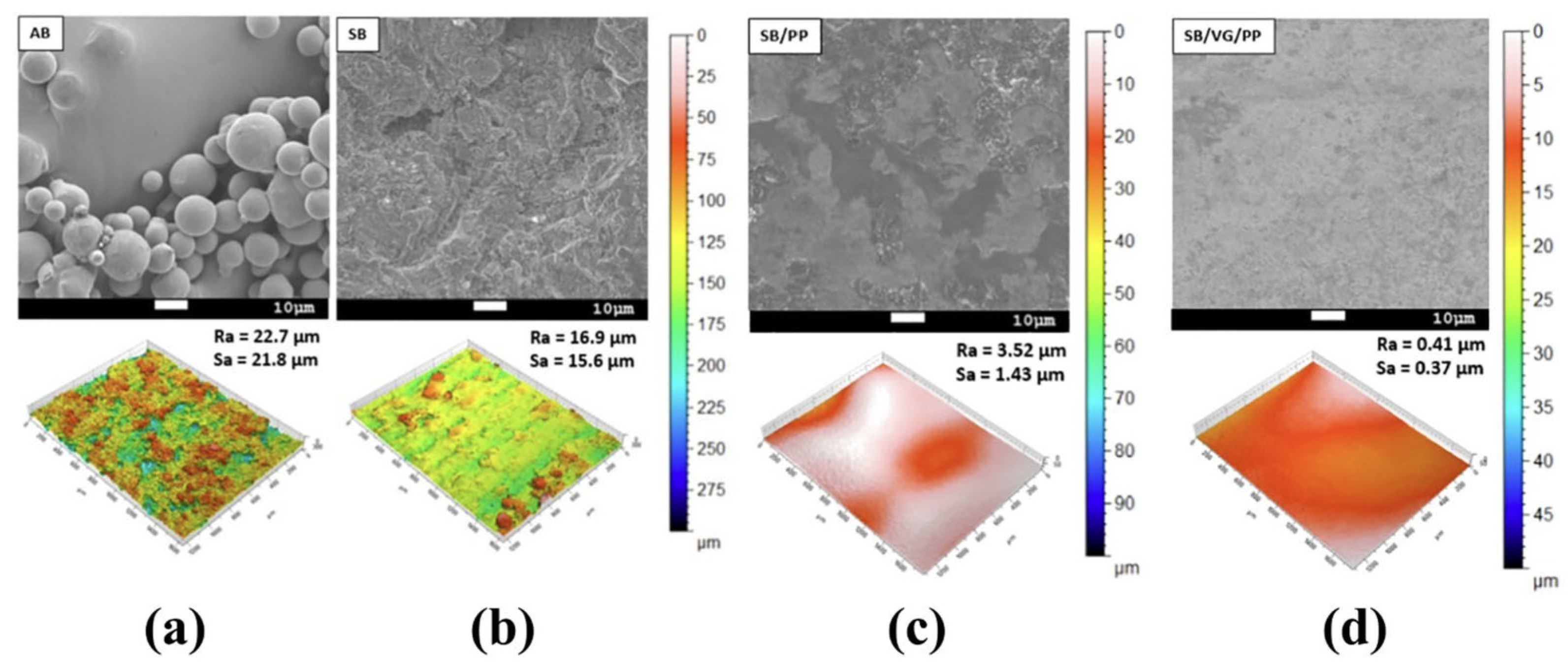
Sehoon et al. [51] used 2–12% Na2CO3 aqueous solution for PEP on WC-Co alloy surfaces to improve TiN coating adhesion on cutting tools. Alloy surface polishing quality depended on WC oxidation and selective solubility. The best surface condition was achieved at 110 V for 40 s. Seo [91] investigated the effect of pep on additively manufactured Co-Cr alloys. The surface roughness of the alloy was first reduced to approximately 3 μm by sandblasting. PEP was then performed at 450 V in an 80 °C (NH4)2SO4 aqueous solution for 8 min. As a result, the surface roughness was further reduced to below 0.02 μm, as shown in Figure 15. At the same time, the PEP generated a layer of Cr oxide on the surface of the alloy to improve the corrosion resistance of the alloy. Aliakseyeu et al. [92] aimed to obtain CoCr alloys with low surface roughness for medical implants, and used a low concentration of NaCl solution as the electrolyte for PEP on Co-Cr alloy. The resulting surface was smooth, with pre-grinding scratches effectively eliminated. At this stage, the surface roughness was reduced from 0.12 μm to 0.05 μm.
The composition of cemented carbide is complex, which makes its polishing process correspondingly more intricate. During the PEP process, excessive voltage should be avoided to prevent ablation of the Co binder. The solution temperature should be maintained around 70 °C to prevent accelerated electrolyte decomposition, and polishing time is best limited to within 5 min. After PEP, cemented carbide both preservd its high hardness and the integrity of the Co phase. The surface morphologies of some typical metal materials before and after plasma electrolytic polishing are shown in Figure 16.

5. Other Plasma Polishing Processes

5.1. Plasma Electrolytic Polishing Removal Process for Coatings

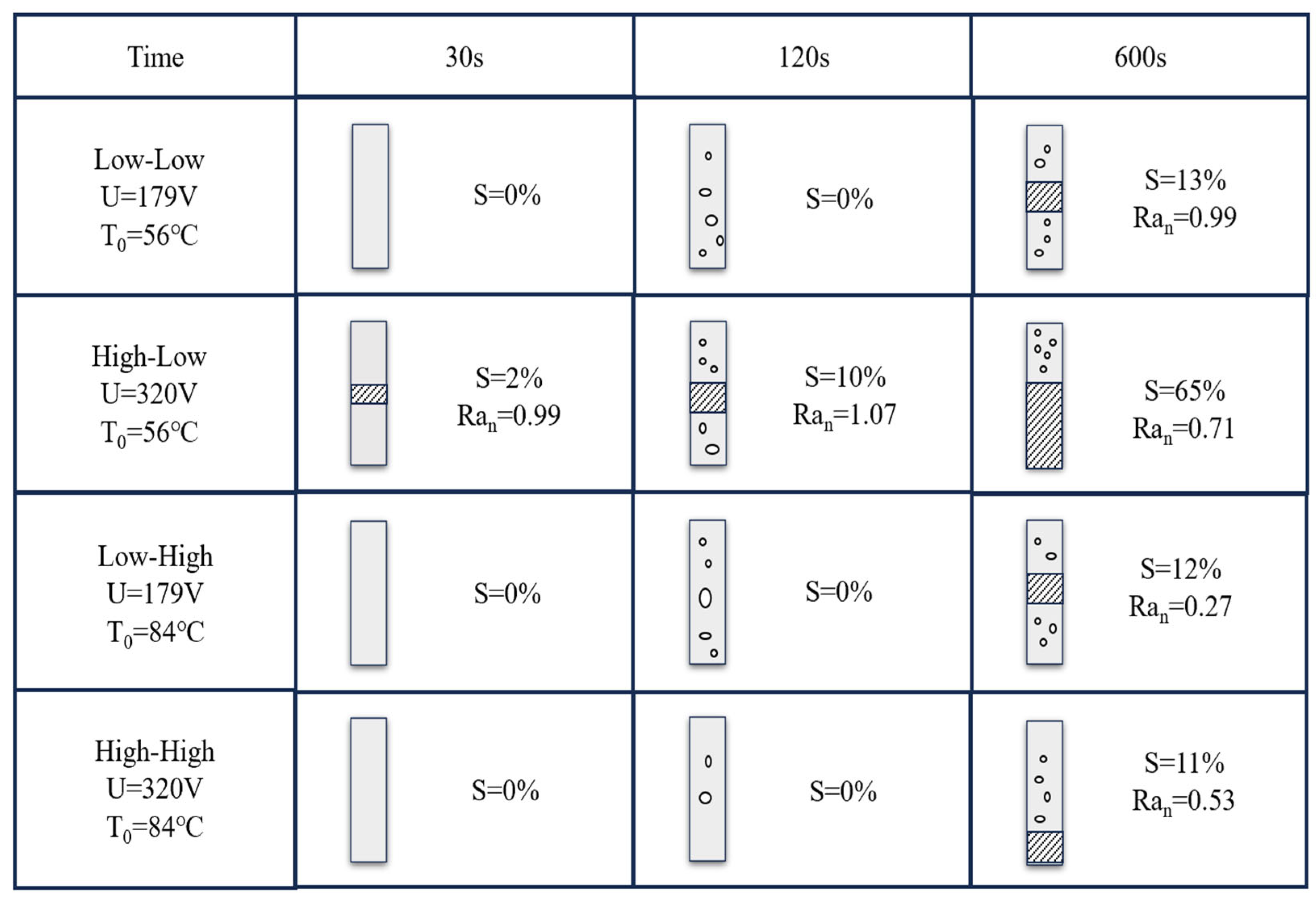
The plasma electrolytic coating removal process is a technology derived from the principles of plasma electrolytic polishing, which removes surface coatings through liquid-phase plasma-driven physical and electrochemical reactions [93,94]. Compared to traditional coating removal methods, it offers several advantages, including high efficiency, energy savings, environmental friendliness, and the absence of induced surface stress. Parfenov et al. [95,96] successfully removed defective TiN coatings from stainless steel using plasma electrolysis in a 5% (NH4)2SO4 solution. By employing mathematical modeling and optimizing polishing time and voltage, the coating was removed with over 25% greater efficiency compared to conventional methods. Nevyantseva et al. [30] investigated the influence of the vapor envelope on coating removal and demonstrated that, during plasma electrolysis treatment, coatings are removed through oxidation occurring at the transient interface of the unstable film near the sample and within the region of boiling bubbles in the vapor envelope. In their study, coating removal was examined by varying the applied voltage over different time intervals. This approach was also employed to explore how the state of the vapor envelope affects the plasma electrolytic coating removal process. As shown in Figure 17, S represents the percentage of the sample surface that is completely free of coating relative to the total area. Raₙ denotes the normalized surface roughness measured within the coating-free regions. The experiment was designed with four modes, and the shaded area in the figure shows the area where the coating was completely removed. After 600 s of plasma electrolysis treatment, portions of the coating remained on the sample surface. The highest coating removal rate was achieved at 56 °C under the high-voltage, low-electrolyte-temperature treatment mode.
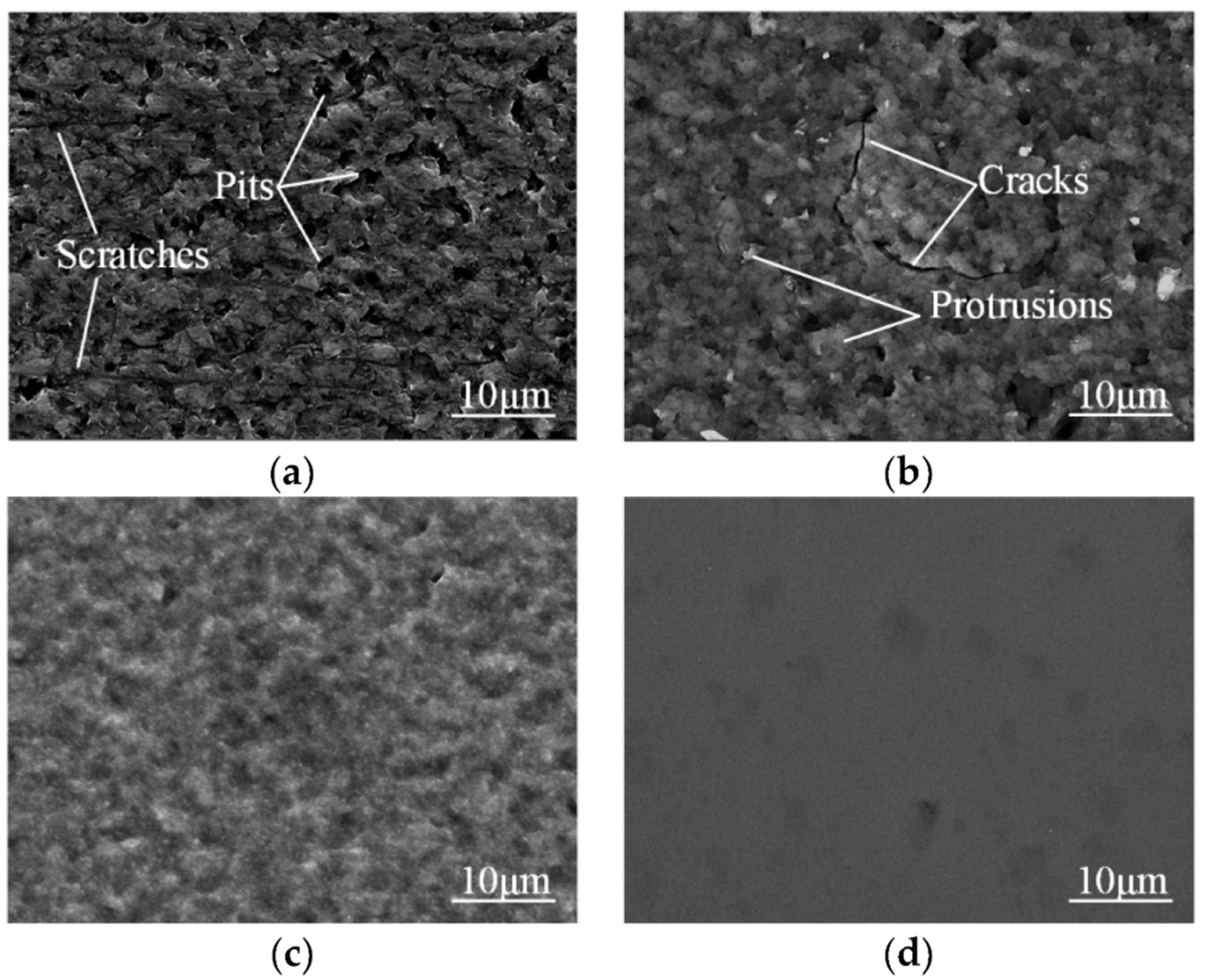
The influence of the vapor envelope on surface morphology can be inferred by analyzing the coating microstructure at different treatment times. Figure 18 presents the typical surface morphology of a sample treated under a high-voltage, low-electrolyte-temperature mode. The results indicate that the coating underwent initial oxidation (Figure 18b), followed by gradual removal through either the mechanical action of bubbles moving across the surface or plasma discharge effects. Coating removal was not uniform and tended to concentrate around existing defects such as scratches (Figure 18c) and pores (Figure 18d). Figure 18e shows the surface after complete coating removal, revealing a lower roughness than the original, which suggests that coating detachment occurs through progressive oxidation, loosening, and eventual separation from the substrate. Micro-discharges form shallow cavities (1–4 μm) on the steel surface, which gradually decrease in depth (to 0.5–1.0 μm in High–Low mode after 600 s). At later stages, the transition to bubble boiling balances oxide formation and removal, it is supposed that with further treatment a significant polishing effect can be obtained.

5.2. Plasma Polishing of Non-Metallic Materials

Plasma electrolytic polishing is typically used for precision polishing of metal surfaces. However, driven by advancements in process development and the demand for smoother surfaces, it has recently been extended to non-metallic materials, particularly semiconductor devices such as SiC and Si. Reducing the surface roughness of 4H-SiC substrates improves power device performance by enhancing breakdown strength and MOS transistor transconductance [97], highlighting the importance of achieving smooth, scratch- and damage-free surfaces. To achieve high MRR without subsurface damage in SiC, Ma et al. [98] proposed combining plasma electrolysis with mechanical polishing (PEP-MP). First, plasma electrolysis modifies the single-crystalline 4H-SiC surface into a soft oxide layer. This layer is then removed by mechanical polishing using soft abrasives (Figure 19). Single-crystal 4H-SiC was placed in NaCl electrolyte at 25 °C, subjected to 200 V for 30 s. Vickers hardness testing revealed a decrease in surface hardness from 2891.03 HV to 72.61 HV, enabling easier mechanical removal. Following mechanical polishing, the SiC surface achieved an ultra-smooth, defect-free finish, the surface roughness decreases from Sz 607 nm, Ra 64.5 nm to Sz 60.1 nm, Ra 8.1 nm, as shown in Figure 20.
Yin et al. [99] treated SiC wafers using plasma electrolysis (0.5% NaCl, 300 V, 5 min) to enhance oxide formation efficiency during subsequent chemical mechanical polishing, thereby facilitating the removal of surface irregularities. Zhang [100] proposed an ultrasonic-assisted electrolyte plasma polishing method, which integrates ultrasonic vibration with plasma oxidation to enhance polishing efficiency without damaging the SiC surface. Experiments conducted in a 1% NaCl solution demonstrated that, under a voltage of 150 V and 20 min of ultrasonic-assisted oxidation, a minimum surface roughness of 0.46 nm was achieved after the oxide layer was removed. Table 10 summarizes research related to partial plasma polishing of SiC.

6. Limitations of Plasma Electrolytic Polishing

After several decades of development, plasma electrolytic polishing technology can be applied to the polishing of nearly all types of metallic components, particularly for the post-processing of materials with complex geometries [103]. However, certain limitations still exist. For example, when polishing tubular workpieces, the Faraday cage effect and constraints imposed by fluid dynamic conditions prevent the formation of a plasma sheath on the inner surface, making it impossible to polish the interior of the workpiece [104]. To address this issue, Cornelsen et al. [105] developed a movable polishing head for the interior surfaces of pipes, which delivers the electrolyte directly to the inner surface to achieve effective polishing. Observations of the steel pipe interior before and after polishing (Figure 21) show a significant improvement in surface smoothness.
The size of the workpiece represents another limitation of PEP. Generally, larger components require more process energy (PES) to maintain a stable polishing process. To address this issue, Küenzi et al. [106] developed a jet-assisted polishing device, which, compared with a conventional electrolyte bath, can polish larger surface areas under the same power consumption, achieving a sixfold increase in polishing rate. Moreover, the nozzle can be actively controlled during polishing, enabling selective material removal and allowing different surface roughness levels to be achieved in specific regions of the workpiece.
Electrolyte degradation and recovery in PEP are also critical considerations. Although PEP primarily employs water-based neutral salts, direct discharge of used electrolyte can still impact the environment, especially at industrial scales. During PEP, portions of the electrolyte may undergo thermal degradation or evaporation due to the applied high voltage and current [93]. Ji et al. [107] investigated the electrochemical behavior of metal cations on 316L stainless steel surfaces and SO42− ions in the electrolyte. They found that under high electric fields, the passive layer on surface protrusions interacts with SO42− and NH4+ ions to form complexes. This leads to the generation of soluble sulfates and water complexes, which enter the electrolyte as free ions and react with hydroxyl radicals to form precipitates, contributing to electrolyte degradation.
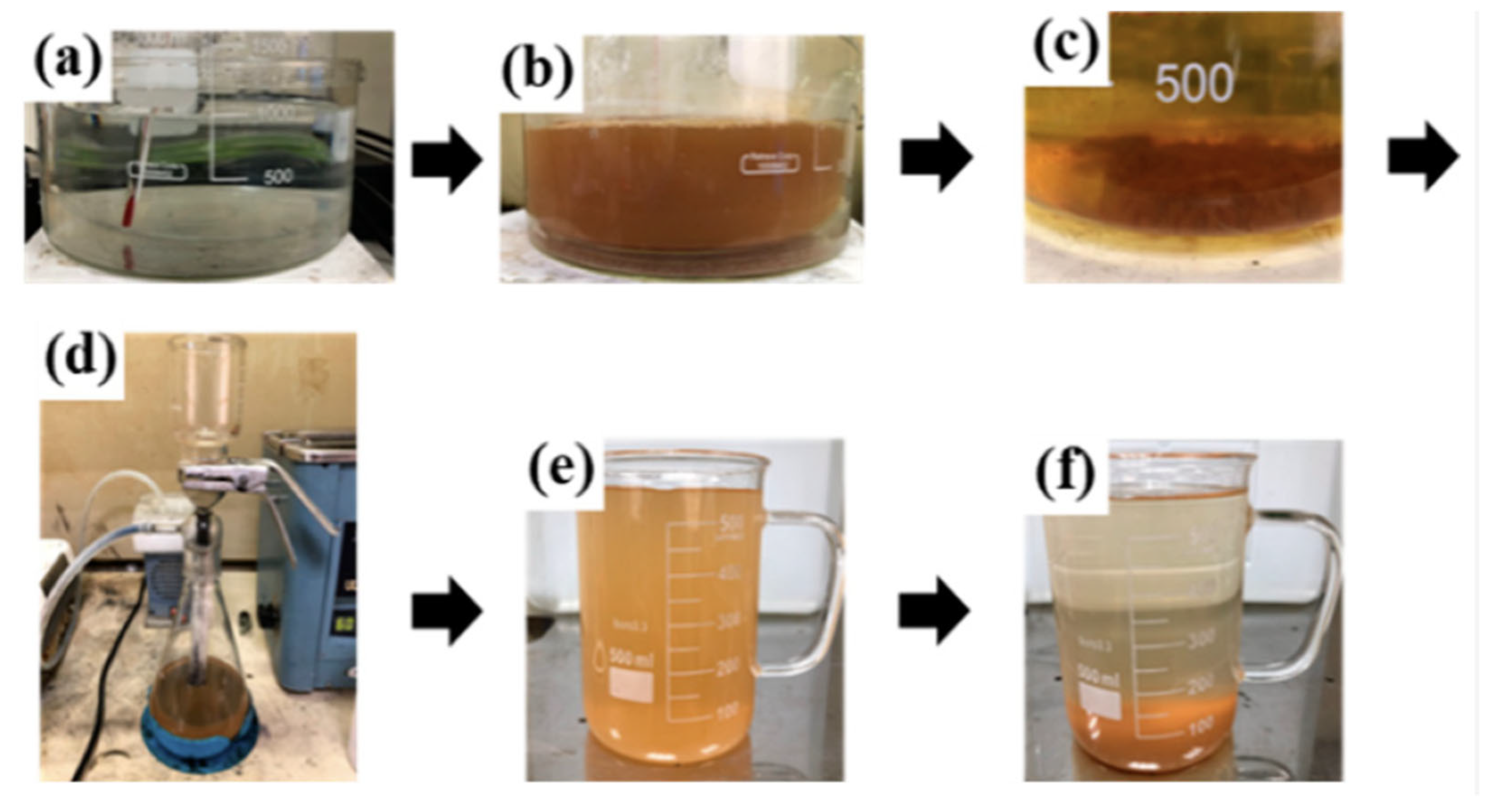
To mitigate waste solution contamination after polishing Zr-based bulk metallic glasses (BMGs), Wang et al. [108] proposed a combined chemical neutralization–flocculation and ion-exchange resin treatment, effectively removing heavy metals and fluoride ions and reducing their concentrations to meet national wastewater standards. Su et al. [109] employed a 2 wt% (NH4)2SO4 aqueous solution to polish SUS304 stainless steel. During polishing, precipitates formed and the solution gradually darkened. To maintain the optimal 2 wt% electrolyte concentration for high-quality surfaces, the electrolyte was filtered to remove precipitates, enabling its recovery and reuse. The process is illustrated in Figure 22.

7. Summary

Plasma Electrolytic Polishing has undergone decades of development, with research focusing on its principles, equipment, process parameters, applicable materials, and surface quality outcomes. PEP has been proven to significantly improve the surface finish and performance of materials. Due to its high efficiency, environmental compatibility, and applicability to complex geometries, it is widely adopted in industry. This paper presents the fundamental principles of PEP and analyzes key factors influencing its effectiveness, including supply voltage, polishing time, electrolyte composition, and temperature. Based on these parameters, a method for improving surface finish is proposed. The application of PEP to various metallic and non-metallic materials is also reviewed. The main conclusions are as follows:
(1) This paper first introduces the working principle of PEP, where a vapor envelope forms between the workpiece and the electrolyte under high voltage. Plasma discharges occur within this vapor envelope, creating discharge channels that selectively remove surface material to achieve polishing. Key factors influencing the polishing effect—namely, voltage, polishing time, electrolyte composition, and temperature are identified, and their mechanisms and effects are systematically discussed to provide a deeper understanding of the PEP process.
(2) In PEP, the workpiece is typically the anode, immersed in an electrolyte bath (cathode: stainless steel wall). Electrolyte composition and temperature vary with material. Applied voltage (100–400 V) induces vapor film formation around the workpiece. This film stabilizes when the peak current decreases by 70–90%. Micro-arc discharges then occur, generating localized high temperatures and pressures enabling polishing. Unlike conventional electrolytic polishing, PEP concentrates energy near the vapor envelope rather than heating the entire system, significantly reducing energy consumption. PEP commonly uses low-concentration neutral salt solutions, lowering solute costs and minimizing waste liquid treatment energy.
(3) PEP is primarily used for alloy surface treatment, especially stainless steel. This paper reviewed PEP applications for stainless steel, titanium alloys, aluminum alloys, copper alloys, and cemented carbides, highlighting influencing factors. Process parameters generally depend on material physicochemical properties. That is, different metal materials correspond to different photoelectric voltages and different electrolyte compositions. (e.g., ammonium salts for stainless steel, fluoride salts for titanium alloys).
(4) PEP is effectively applied for coating removal and the surface treatment of non-metallic materials. In coating removal, the process parallels PEP, where the coating is oxidized and then mechanically stripped by bubbles traversing the sample surface within the vapor envelope, achieving approximately 25% higher efficiency than conventional methods. For non-metallic materials, PEP is typically integrated with mechanical polishing: the surface is first modified into a softened oxide layer via PEP, which is subsequently refined with soft abrasives. This synergistic approach not only enhances process efficiency but also produces an ultra-smooth, defect-free surface.

8. Future Prospect

Plasma electrolytic polishing is still in the experimental stage, restricted by the lack of standardized process parameters and systematic theoretical models, which limits reproducibility and industrial application. Inconsistent definitions of electrolyte concentration, voltage, and processing time hinder result comparison and scaling. Moreover, the vapor envelope composition and discharge mechanisms remain unclear, emphasizing the need for unified theoretical models and simulation tools to optimize parameters and reduce trial-and-error.
Combining PEP with external fields such as magnetic or ultrasonic assistance shows potential to improve surface quality, particularly for complex additive manufacturing (AM) parts. However, the long-term performance stability of PEP-treated surfaces has not been systematically verified. Key indicators such as wear resistance, corrosion resistance, and roughness degradation under extended service conditions require thorough evaluation. Conducting long-term reliability tests, such as cyclic wear and corrosion monitoring under industrial conditions, is essential. In addition, the PEP process can be integrated with computational programs, allowing specific algorithms to be applied based on the characteristics of the workpiece to be polished. This enables precise control of the polishing process and maximization of polishing efficiency. Collectively, advancing parameter standardization, theoretical modeling, and durability verification will constitute critical directions in the future development of PEP.

Author Contributions

Conceptualization, T.Y. and S.W.; validation, T.Y., S.W. and W.H.; investigation, T.Y., R.J. and J.Z.; resources, W.H., R.J., J.Z. and Y.Z. (Yongchun Zou); data curation, W.H., R.J., J.Z. and Y.Z. (Yongchun Zou); writing—original draft preparation, R.J., J.Z.; writing—review and editing, S.W. and J.O.; visualization, S.W., W.H. and J.O.; supervision, Y.W. and Y.Z. (Yu Zhou); funding acquisition, Y.W. All authors have read and agreed to the published version of the manuscript.

Funding

This research was funded by Aeronautical Science Foundation (2023M045077001), Open Project Funding of State Key Laboratory for High Performance Tools (GXNGJSKL 2024), and Opening Project Fund of Materials Service Safety Assessment Facilities (MSAF-2024-007).The APC was funded by IOAP Discount and Discount Voucher.

Data Availability Statement

No applicable.

Acknowledgments

The partial supports from the Aeronautical Science Foundation (2023M045077001), Open Project Funding of State Key Laboratory for High Performance Tools (GXNGJSKL 2024), and Opening Project Fund of Materials Service Safety Assessment Facilities (MSAF-2024-007) are gratefully acknowledged.

Conflicts of Interest

All authors were employed by the company State Key Laboratory for High Performance Tools, Chengdu Tool Research Institute Co., Ltd. The remaining authors declare that the research was conducted in the absence of any commercial or financial relationships that could be construed as a potential conflict of interest.

References

  1. Kusmanov, S.; Tambovskiy, I.; Korableva, S.; Silkin, S.; Naumov, A. Modification of Steel Surface by Anodic Plasma Electrolytic Boriding and Polishing. Trans. Indian. Inst. Met. 2022, 75, 3185–3192. [Google Scholar] [CrossRef]
  2. Liang, S.Y.; Shih, A.J. Electrochemical machining. chemical machining and chemical mechanical polishing processes. In Analysis of Machining and Machine Tools; Springer: Boston, MA, USA, 2016; pp. 181–191. [Google Scholar]
  3. Li, Y.; Liu, J.Q.; Li, J.S. Metal Surface Polishing Technology; Chemical Industry Press: Beijing, China, 2006. [Google Scholar]
  4. Fang, J.L. Metal Material Polishing Technology; National Defense Industry Press: Beijing, China, 2007. [Google Scholar]
  5. Duradzhi, V.N.; Bryantsev, I.V.; Tokarov, A.K. Investigation of erosion of the anode under the action of an electrolytic plasma on it. Elektron. Obrab. Mater. 1979, 5, 15–19. [Google Scholar]
  6. Hans, H.; Eckart, R.; Klaus, R.; Egbert, K.; Jan, P. Method for Highly Glaining Power-Conductive Workstuffs in Anodic Electrolyte Plasma. Patent DD238074A1, 6 August.
  7. Stanishevsky, V.K.; Parshuto, A.E.; Kosobutsky, A.A.; Semenenko, L.M.; Tikhonovsky, V.N.; Khlebtsevich, V.A.; Velichko, L.S.; Semchenko, A.A.; Slepnev, G.E. Method of Electrochemical Machining of Articles Made of Conducting Materials. U.S. Patent No. 5.028.304, 2 July 1991. [Google Scholar]
  8. Nestler, K.; Böttger-Hiller, F.; Adamitzki, W.; Glowa, G.; Zeidler, H.; Schubert, A. Plasma electrolytic polishing–an overview of applied technologies and current challenges to extend the polishable material range. Procedia Cirp 2016, 42, 503–507. [Google Scholar] [CrossRef]
  9. Huang, Y.; Wang, C.; Ding, F.; Yang, Y.; Zhang, T.; He, X.; Zheng, L.; Li, N. Principle. process. and application of metal plasma electrolytic polishing: A review. Int. J. Adv. Manuf. Technol. 2021, 114, 1893–1912. [Google Scholar] [CrossRef]
  10. Zeidler, H.; Böttger-Hiller, F. Plasma-electrolytic polishing as a post-processing technology for additively manufactured parts. Chem. Ing. Tech. 2022, 94, 1024–1029. [Google Scholar] [CrossRef]
  11. Zeidler, H.; Meyer, W.; Loeser, C.; Adamitzki, W.; Nestler, K. Changes on surfaces of electrodes in aqueous electrolytic solutions at high voltages. In Proceedings of the 9th International Symposium on Electro Chemical Machining Technology INSECT, Chemnitz, Germany, 12–13 November 2013. [Google Scholar]
  12. Parfenov, E.V.; Yerokhin, A.; Nevyantseva, R.R.; Gorbatkov, M.V.; Liang, C.J.; Matthews, A. Towards smart electrolytic plasma technologies: An overview of methodological approaches to process modelling. Surf. Coat. Technol. 2015, 269, 2–22. [Google Scholar] [CrossRef]
  13. Kalenchukova, O.V.; Nagula, P.K.; Tretinnikov, D.L. About changes in the chemical composition of the electrolyte in the process of electrolytic-plasma treatment of materials. Mater. Methods Technol. 2015, 9, 404–413. [Google Scholar]
  14. Yerokhin, A.L.; Nie, X.; Leyland, A.; Matthews, A.; Dowey, S.J. Plasma electrolysis for surface engineering. Surf. Coat. Technol. 1999, 122, 73–93. [Google Scholar] [CrossRef]
  15. Hickling, A. Electrochemical Processes in Glow Discharge at the Gas Solution Interface. In Modern Aspect of Electrochemistry; Springer: Boston, MA, USA, 1971; No 6. [Google Scholar]
  16. Sengupta, S.K.; Singh, O.P. Contact glow discharge electrolysis: A study of its chemical yields in aqueous inert-type electrolytes. J. Electroanal. Chem. 1994, 369, 113–120. [Google Scholar] [CrossRef]
  17. Mazza, B.; Pedeferri, P.; Re, G. Hydrodynamic instabilities in electrolytic gas evolution. Electrochim. Acta 1978, 23, 87–93. [Google Scholar] [CrossRef]
  18. Podhorský, Š. Utilisation of Plasma Discharges in Electrolyte for Surface Finishing of Stainless Steels; Hochsch. Anhalt (FH): Bernburg, Germany, 2015. [Google Scholar]
  19. Beckmann-Lnstitut Fuer Technologieentwicklung, De. Device for Plasma Polishing Using a Liquid Electrolyte. Germany Patent DE202008011646U1, 2 September 2008. [Google Scholar]
  20. Ji, G.; Ma, L.; Wu, L. Effect of the gas layer evolution on electrolytic plasma polishing of stainless steel. Sci. Rep. 2024, 14, 22099. [Google Scholar] [CrossRef]
  21. Parfenov, E.V.; Mukaeva, V.R.; Farrakhov, R.G. Plasma electrolytic treatments for advanced surface finishing technologies. Mater. Technol. Des. 2019, 1, 34–41. [Google Scholar]
  22. Kellogg, H.H. Anode effect in aqueous electrolysis. J. Electrochem. Soc. 1950, 97, 133. [Google Scholar] [CrossRef]
  23. Plotnikov, N.V.; Smyslov, A.M.; Timindarov, D.R. To the question of the model of electrolyte-plasma polishing of the surface. Bull. UGATU 2013, 17, 4. [Google Scholar]
  24. Zakharov, S.V.; Korotkikh, M.T. Electrolyte-Plasma Polishing Ionization Model. In Advances in Mechanical Engineering; Evgrafov, A., Ed.; Lecture Notes in Mechanical Engineering; Springer: Cham, Switzerland, 2020. [Google Scholar] [CrossRef]
  25. Cornelsen, M.; Deutsch, C.; Seitz, H. Electrolytic plasma polishing of pipe inner surfaces. Metals 2017, 8, 12. [Google Scholar] [CrossRef]
  26. Wang, J.; Suo, L.C.; Guan, L.L.; Fu, Y.L. Analytical study on mechanism of electrolysisand plasma polishing. J. Adv. Mater. Res. 2012, 472, 350–353. [Google Scholar] [CrossRef]
  27. Podhorský, Š.; Malík, A. The possibilities of plasma polishing of the steel DIN 1.0570 in electrolyte. In Proceedings of the 19th Conference Metal, Roznov pod Radhostem, Czech Republic, 18–20 May 2010. [Google Scholar]
  28. Volenko, A.; Boychenko, O.V.; Chirkunova, N.V. Introduction of technology of electrolytic-plasma polishing of metal goods. Vektor Nauki Tol’yattinskogo Gosudarstvennogo Universiteta. 2016, 1, 11–16. [Google Scholar] [CrossRef]
  29. Danilov, I.; Hackert-Oschätzchen, M.; Schaarschmidt, I.; Zinecker, M.; Schubert, A. Transient simulation of the removal process in plasma electrolytic polishing of stainless steel. In Proceedings of the COMSOL Conference, Lausanne, Switzerland, 22–24 October 2018. [Google Scholar]
  30. Nevyantseva, R.R.; Gorbatkov, S.A.; Parfenov, E.V.; Bybin, A.A. The influence of vapor–gaseous envelope behavior on plasma electrolytic coating removal. Surf. Coat. Technol. 2001, 148, 30–37. [Google Scholar] [CrossRef]
  31. Zeidler, H.; Boettger-Hiller, F.; Edelmann, J.; Schubert, A. Surface finish machining of medical parts using plasma electrolytic polishing. Procedia CIRP 2016, 49, 83–87. [Google Scholar] [CrossRef]
  32. Ablyaz, T.R.; Muratov, K.R.; Kochergin, E.U.; Shakirzanov, T. Improving the quality of the surfacesof products obtained by electrical discharge machining using electrolytic-plasma polishing technology. Bull. PNRPU Mech. Eng. Mater. Sci. 2018, 20, 86–93. [Google Scholar]
  33. Dobrynin, D.A. Electrolytic-plasma polishing of VT6 and VT8M-1 titanium alloys. Tr. VIAM 2017, 7, 14–23. [Google Scholar]
  34. Gupta, P.; Tenhundfeld, G.; Daigle, E.O.; Ryabkov, D. Electrolytic plasma technology: Science and engineering—An overview. Surf. Coat. Technol. 2007, 201, 8746–8760. [Google Scholar] [CrossRef]
  35. Klapkiv, M.D. State of Electrolytic Plasma in the Process of Synthesis of Oxides Based on Aluminum. Mater. Sci. 1995, 31, 494–499. [Google Scholar] [CrossRef]
  36. Chen, Y.M. Cavitation Erosion. In ASM Handbook; ASM International: Metals Park, OH, USA, 2003; p. 11. [Google Scholar]
  37. Zhou, C.; Su, H.; Qian, N.; Zhang, Z.; Xu, J. Characteristics and function of vapour gaseous envelope fluctuation in plasma electrolytic polishing. Int. J. Adv. Manuf. Technol. 2022, 119, 7815–7825. [Google Scholar] [CrossRef]
  38. Wang, J.; Zong, X.; Liu, J.; Feng, S. Influence of voltage on electrolysis and plasma polishing. In Proceedings of the 2017 International Conference on Manufacturing Engineering and Intelligent Materials (ICMEIM 2017), Guangzhou, China, 25–26 February 2017. [Google Scholar]
  39. Parfenov, E.V.; Farrakhov, R.G.; Mukaeva, V.R.; Gusarov, A.V.; Nevyantseva, R.R.; Yerokhin, A. Electric field effect on surface layer removal during electrolytic plasma polishing. Surf. Coat. Technol. 2016, 307, 1329–1340. [Google Scholar] [CrossRef]
  40. Belkin, P.N.; Kusmanov, S.A.; Parfenov, E.V. Mechanism and technological opportunity of plasma electrolytic polishing of metals and alloys surfaces. Appl. Surf. Sci. Adv. 2005, 1, 100016. [Google Scholar] [CrossRef]
  41. Cao, C.B. A Polishing Solution and Polishing Method for Amorphous Alloys. China Patent CN102453444A, 15 May 2012. [Google Scholar]
  42. Yerokhin, A.; Pilkington, A.; Matthews, A. Pulse current plasma assisted electrolytic cleaning of AISI 4340 steel. J. Mater. Process. Technol. 2010, 210, 54–63. [Google Scholar] [CrossRef]
  43. Kulikov, I.S.; Vashenko, S.V.; Kamenev, A.Y. Electrolytic Plasma Processing of Materials; Belarusian Science, Republic of Belarus: Minskaja voblasć, Belarus, 2010; ISBN 978-985-08-1215-5. [Google Scholar]
  44. Kusmanov, S.A.; Tambovskiy, I.V.; Kusmanova, I.A.; Belkin, P.N. Some features of anodic plasma electrolytic processes in aqueous solution. J. Phys. Conf. Ser. 2019, 1396, 012025. [Google Scholar] [CrossRef]
  45. Sinkevich, Y.V.; Sheleg, V.K.; Yankovsky, I.N. Investigation of metal current efficiency during electropulse polishing of structural carbon steels. Vestn. Baranivichi State. Univ. Ser. Fiz-Math Nauk. 2013, 1, 125–130. [Google Scholar]
  46. Wang, J.; Suo, L.; Guan, L.; Fu, Y. Optimization of Processing Parameters for Electrolysis and Plasma Polishing. Appl. Mech. Mater. 2012, 217–219, 1368–1371. [Google Scholar] [CrossRef]
  47. Podhorský, Š.; Bajčičák, M. Plasma Polishing of Stainless Steels–The Electrolyte Concentration Vs. Gloss. Level. Research Papers Faculty of Materials Science and Technology Slovak. Univ. Technol. 2018, 26, 171–176. [Google Scholar]
  48. Rajput, A.S.; Zeidler, H.; Schubert, A. Analysis of voltage and current during the plasma electrolytic polishing of stainless steel. In Proceedings of the 17th International Conference European Society Precision Engineering Nanotechnology, Hannover, Germany, 29 May–2 June 2017; pp. 2–3. [Google Scholar]
  49. Dobrynin, D. Electrolytic-plasma polishing of titanium alloys VT6 and VT8M-1. Proc. VIAM 2017, 5, 14–24. [Google Scholar]
  50. Vaňa, D.; Stefanpodhorsky; Suba, R.; Hurajt, M. The change of surface properties on tested smooth stainless steel surfaces after plasma polishing. Int. J. Eng. Sci. Invent. 2013, 2, 7–11. [Google Scholar]
  51. An, S.; Foest, R.; Fricke, K.; Riemer, H.; Fröhlich, M.; Quade, A.; Schäfer, J.; Weltmann, K.D.; Kersten, H. Pretreatment of cutting tools by plasma electrolytic polishing (PEP) for enhanced adhesion of hard coatings. Surf. Coat. Technol. 2021, 405, 126504. [Google Scholar] [CrossRef]
  52. Aliakseyeu, Y.G.; Korolyov, A.Y.; Niss, V.S.; Parshuto, A.E.; Budnitskiy, A.S. Electrolyte-plasma polishing of titanium and niobium alloys. Sci. Tech. 2018, 17, 211–219. [Google Scholar] [CrossRef]
  53. Valentinčič, J.; Koroth, J.E.; Zeidler, H. Advancements in surface finish for additive manufacturing of metal parts: A comprehensive review of plasma electrolytic polishing (PEP). Virtual Phys. Prototyping 2024, 19, e2364222. [Google Scholar] [CrossRef]
  54. Mihal, O.V.; Moroz, O.V.; Starovoytov, R.I.; Lytovchenko, S.V.; Mazilin, B.A.; Iliushyn, L.O. Dynamics of the plasma electrolytic polishing process of austenitic steel AISI 304 in a solution of ammonium sulfate. Вoпрoсы атoмнoй науки и техники 2018, 5, 126–131. [Google Scholar]
  55. Löber, L.; Flache, C.; Petters, R.; Kühn, U.; Eckert, J. Comparison of different post processing technologies for SLM generated 316 l steel parts. Rapid Prototyp. 2013, 19, 173–179. [Google Scholar] [CrossRef]
  56. Zeidler, H.; Aliyev, R.; Gindorf, F. Efficient finishing of laser beam melting additive manufactured parts. Manuf. Mater. Process 2021, 5, 106. [Google Scholar] [CrossRef]
  57. Loaldi, D.; Kain, M.; Haahr-Lillevang, L.; Vedel-Smith, N.K.; Tosello, G. Comparison of Selective Laser Melting Post-Processes based on Amplitude and Functional Surface Roughness parameters. In Proceedings of the Joint Special Interest Group Meeting Between Euspen and ASPE Advancing Precision in Additive Manufacturing, Nantes, France, 16–18 September 2019. [Google Scholar]
  58. Ablyaz, T.R.; Muratov, K.R.; Radkevich, M.M.; Ushomirskaya, L.A.; Zarubin, D.A. Electrolytic plasma surface polishing of complex components produced by selective laser melting. Russ. Eng. Res. 2018, 38, 491–492. [Google Scholar] [CrossRef]
  59. Yang, L.; Laugel, N.; Housden, J.; Espitalier, L.; Matthews, M.; Yerokhin, A. Plasma additive layer manufacture smoothing (PALMS) technology–an industrial prototype machine development and a comparative study on both additive manufactured and conventional machined AISI 316 stainless steel. Addit. Manuf. 2020, 34, 101204. [Google Scholar] [CrossRef]
  60. Kashapov, L.N.; Kashapov, N.F.; Kashapov, R.N.; Denisov, D.G. Plasma electrolytic treatment of products after selective laser melting. Phys. Conf. Ser. 2016, 669, 12029. [Google Scholar] [CrossRef]
  61. Muratov, K.R.; Gashev, E.A.; Ablyaz, T.R. Recommendations for electrolytic plasma polishing of chromium and titanium alloys. Russ. Eng. Res. 2022, 42, 829–831. [Google Scholar] [CrossRef]
  62. Navickaite, K.; Nestler, K.; Kain, M.; Guido, T.; Matteo, C.; David, P.; Michael, P.; Falko, B.H.; Zeidler, H. Effective polishing of inner surfaces of additive manufactured inserts for polymer extrusion using Plasma Electrolytic Polishing. In Proceedings of the 18th Rapid. Tech 3D, Erfurt, Germany, 17–19 May 2022. [Google Scholar]
  63. Sabotin, I.; Jerman, M.; Lebar, A.; Valentinčič, J.; Böttger, T.; Kühnel, L.; Zeidler, H. Effects of plasma electrolytic polishing on SLM printed microfluidic platform. Adv. Technol. Mater. 2022, 47, 19–23. [Google Scholar] [CrossRef]
  64. Wang, J.; Zhang, L.; Cheng, J.; Liu, J.; Zou, Y.; Zhang, C.; Wei, D.; Cheng, S.; Wang, Y. Optimization of electrolytic plasma polishing process and surface performance analysis for 6061 aluminum alloy. Mater. Today Commun. 2024, 40, 110162. [Google Scholar] [CrossRef]
  65. Wong, K.; Ho, J.Y.; Wong, T.N. Fabrication of heat sinks by Selective Laser Melting for convective heat transfer applications. Virtual Phys. Prototyp. 2016, 11, 159–165. [Google Scholar] [CrossRef]
  66. Smirnov, A.S.; Galinovsky, A.L.; Martysyuk, D.A. Reducing additive product surface roughness by electrochemical processing methods. proceedings of higher educational institutions. Маchine Build. 2022, 16–23. [Google Scholar] [CrossRef]
  67. Duradji, V.N.; Kaputkin, D.E.; Duradji, A.Y. Aluminum Treatment in the Electrolytic Plasma During the Anodic Process. J. Eng. Sci. Technol. Review. 2017, 10, 81–84. [Google Scholar] [CrossRef]
  68. Gaysin, A.F.; Gil’mutdinov, A.K.; Mirkhanov, D.N. Electrolytic-plasma treatment of the surface of a part produced with the use of additive technology. Met. Sci. Heat. Treat. 2018, 60, 128–132. [Google Scholar] [CrossRef]
  69. Zakharov, S.V.; Korotkikh, M.T. Electrolytic plasma processing of complex products from aluminum alloy D16. Вестник Кoнцерна ВКО Алмаз-Антей 2017, 3, 22. [Google Scholar] [CrossRef]
  70. Kui, Q. Research on Optimization and Application of Aluminium Formula Based on the Small Electrolysis Plasma Polishing Machine. Master’s Thesis, Harbin Institute of Technology, Harbin, China, 2015. [Google Scholar]
  71. Calin, M.; Zhang, L.-C.; Attar, H.; Eckert, J. Review on manufacture by selective laser melting and properties of titanium based materials for biomedical applications. Mater. Technol. 2016, 31, 66–76. [Google Scholar]
  72. Singla, A.K.; Banerjee, M.; Sharma, A.; Singh, J.; Bansal, A.; Gupat, M.K.; Khanna, N.; Shahi, A.S.; Goyal, D.K. Selective laser melting of Ti6Al4 V alloy: Process parameters. defects and post-treatments. Manuf. Process 2021, 64, 161–187. [Google Scholar] [CrossRef]
  73. Navickaitė, K.; Nestler, K.; Böttger-Hiller, F.; Matias, C.; Diskin, A.; Golan, O.; Garkun, A.; Strokin, E.; Biletskiy, R.; Safranchik, D.; et al. Efficient polishing of additive manufactured titanium alloys. Proc. CIRP 2022, 108, 346–351. [Google Scholar] [CrossRef]
  74. Bernhardt, A.; Schneider, J.; Schroeder, A.; Papadopoulous, K.; Lopez, E.; Brückner, F.; Botzenhart, U. Surface conditioning of additively manufactured titanium implants and its influence on materials properties and in vitro biocompatibility. Mater. Sci. Eng. C 2021, 119, 111631. [Google Scholar] [CrossRef]
  75. Lingath, K.; Zeidler, H.; Parshuta, A. Plasma Polishing of Objects Made of Titanium or Titanium Alloys Comprises Applying a Voltage to the Object Positioned in a Warm Aqueous Electrolyte Solution, Followed by Processing Using Plasma Polishing. Germany Patent DE10207632A1, 22 February 2002. [Google Scholar]
  76. Smyslova, M.K.; Tamindarov, D.R.; Plotnikov, N.V.; Modina, I.M.; Semenova, I.P. Surface electrolytic-plasma polishing of Ti-6Al-4V alloy with ultrafine-grained structure produced by severe plastic deformation. IOP Conf. Ser. Mater. Sci. Eng. IOP Publ. 2018, 461, 012079. [Google Scholar] [CrossRef]
  77. Parfenov, E.V.; Neviantseva, R.R.; Gorbatkov, S.A.; Yerokhin, A. Plasma Electrolytic Treatment: Modelling. Diagnostics. Control; Mashinostrojenije: Moscow, Russia, 2014. [Google Scholar]
  78. Smyslov, A.M.; Smyslova, M.K.; Mingazhev, A.D.; Selivanov, K.S. Multi-Stage Electrolyte-Plasma Processing of Products from Titanium and Titanium Alloys; Ufa State Aviation Technical University: Moscow, Russia, 2009; pp. 141–145. [Google Scholar]
  79. Beck, U.; Lange, R.; Neumann, H.-G. Micro- and Nanoscaled Titanium Surface Structures Textured by Electrolytic Plasma and Etching Methods. Adv. Mater. Res. 2006, 15–17, 141–146. [Google Scholar] [CrossRef]
  80. Reinhardt, F.; Böttger-Hiller, F.; Kranhold, C.; Schulze, H.P.; Kröning, O.; Zeidler, H.; Lampke, T. Surface modification for corrosion resistance of electric conductive metal surfaces with plasma electrolytic polishing. AIP Conf. Proc. 2019, 2113, 110009. [Google Scholar] [CrossRef]
  81. Duradji, V.N.; Kaputkin, D.E. Metal Surface Treatment in Electrolyte Plasma during Anodic Process. J. Electrochem. Soc. 2015, 163, E43–E48. [Google Scholar] [CrossRef]
  82. Valiev, R.I.; Khafizov, A.A.; Shakirov, Y.I.; Sushchikova, A.N. Polishing and deburring of machine parts in plasma of glow discharge between solid and liquid electrodes. IOP Conf. Ser. Mater. Sci. Eng. 2015, 86, 012026. [Google Scholar] [CrossRef]
  83. Huang, Z.P. Copper Alloy Electrolyte-Plasma Polishing Method. Master’s Thesis, Harbin Institute of Technology, Harbin, China, 2012. [Google Scholar]
  84. Duradji, V.N.; Kaputkin, D.E.; Duradji, A.Y. Method of Plasma Electrolytic Treatment of Metal Surface. Russian Patent 2537346, 10 January 2015. [Google Scholar]
  85. Bottger-Hiller, F.; Nestler, K.; Zeidler, H.; Glowa, G.; Lampke, T. Plasma Electrolytic Polishing of Metalized Carbon Fibers. AIMS Mater. Sci. 2016, 3, 260–269. [Google Scholar] [CrossRef]
  86. Zhang, C.R. Mechanism and Process Optimization of Plasma Electropolishing on the Surface of Aluminum, Titanium Alloy and Copper. Master’s Thesis, Harbin Institute of Technology, Harbin, China, 2021. [Google Scholar]
  87. Bobzin, K. High-performance coatings for cutting tools. CIRP J. Manuf. Sci. Technol. 2016, 18, 1–9. [Google Scholar] [CrossRef]
  88. Helmersson, U.; Lattemann, M.; Bohlmark, J.; Ehiasarian, A.P.; Gudmundsson, J.T. Ionized physical vapor deposition (IPVD): A review of technology and applications. Thin Solid Film. 2006, 513, 1–24. [Google Scholar] [CrossRef]
  89. Seo, B.; Park, H.-K.; Park, K.B.; Kang, H.-S.; Park, K. Effect of hydrogen peroxide on Cr oxide formation of additive manufactured CoCr alloys during plasma electrolytic polishing. Mater. Lett. 2021, 294, 129736. [Google Scholar] [CrossRef]
  90. Nagulin, K.Y.; Terent’ev, A.A.; Belov, M.D.; Gil’mutdinov, A.K. Electrolytic-plasma jet polishing of additively manufactured gas turbine engine components. Russ. Aeronaut. 2022, 65, 822–830. [Google Scholar] [CrossRef]
  91. Seo, B.; Park, H.K.; Kim, H.G.; Kim, W.R.; Park, K. Corrosion behavior of additive manufactured CoCr parts polished with plasma electrolytic polishing. Surf. Coat. Technol. 2021, 406, 126640. [Google Scholar] [CrossRef]
  92. Aliakseyeu, Y.G.; Korolyov, A.Y.; Niss, V.S. Electrolytic-plasma polishing of cobalt-chromium alloys for medical products. Proceedings of the National Academy of Sciences of Belarus. Phys.-Tech. Ser. 2019, 64, 296–303. [Google Scholar] [CrossRef]
  93. Danilov, I.; Hackert-Oschätzchen, M.; Zinecker, M.; Meichsner, G.; Edelmann, J.; Schubert, A. Process understanding of plasma electrolytic polishing through multiphysics simulation and inline metrology. Micromachines 2019, 10, 214. [Google Scholar] [CrossRef] [PubMed]
  94. Amirkhanova, N.A.; Nevyantseva, R.R.; Belonogov, V.A.; Timergazina, T.M. Russian Patent 2094546, 30 October 1997.
  95. Parfenov, E.V.; Nevyantseva, R.R.; Gorbatkov, S.A. Process control for plasma electrolytic removal of TiN coatings. Part 1: Duration control. Surf. Coat. Technol. 2005, 199, 189–197. [Google Scholar] [CrossRef]
  96. Parfenov, E.V.; Nevyantseva, R.R.; Gorbatkov, S.A. Process control for plasma electrolytic removal of TiN coatings: Part 2: Voltage control. Surf. Coat. Technol. 2005, 199, 198–204. [Google Scholar] [CrossRef]
  97. Ohmi, T.; Miyashita, M.; Itano, M.; Imaoka, T.; Kawanabe, I. Dependence of thin-Oxide films quality on surface microroughness. IEEE Trans. Electron. Devices 1922, 39, 537–545. [Google Scholar] [CrossRef]
  98. Ma, G.; Li, S.; Liu, X.; Yin, X.; Jia, Z.; Liu, F. Combination of Plasma Electrolytic Processing and Mechanical Polishing for Single-Crystal 4H-SiC. Micromachines 2021, 12, 606. [Google Scholar] [CrossRef]
  99. Yin, X.; Li, S.; Ma, G.; Jia, Z.; Liu, X. Investigation of oxidation mechanism of SiC single crystal for plasma electrochemical oxidation. RSC Adv. 2021, 11, 27338–27345. [Google Scholar] [CrossRef] [PubMed]
  100. Zhang, C. Simulation and Experimental Study on Ultrasonic Assisted Electrolyte Plasma Polishing of SiC Single Crystal. Master’s Thesis, Xi’an University of Technology, Xi’an, China, 2023. [Google Scholar]
  101. Yamamura, K.; Takiguchi, T.; Ueda, M.; Deng, H.; Hattori, A.N.; Zettsu, N. Plasma assisted polishing of single crystal SiC for obtaining atomically flat strain-free surface. CIRP Ann. 2011, 60, 571–574. [Google Scholar] [CrossRef]
  102. Deng, H.; Yamamura, K. XTEM Observation of 4H-SiC (0001) Surfaces Processed by Plasma Assisted Polishing. Adv. Mater. Res. 2012, 497, 156–159. [Google Scholar] [CrossRef]
  103. Schorn, L.; Wilkat, M.; Lommen, J.; Borelli, M.; Muhammad, S.; Rana, M. Plasma Electrolytic Polished Patient-Specific Orbital Implants in Clinical Use-A Technical Note. J. Pers. Med. 2023, 13, 148. [Google Scholar] [CrossRef]
  104. Navickaitė, K.; Langenhan, S.; Köckritz, J.; Sherstneva, A.; Nestler, K.; Penzel, M.; Wendler, M.; Szlosarek, R.; Hauser, M.; Volkova, O.; et al. Three modes of plasma electrolytic polishing of high-alloy austenitic steel. Results Surf. Interfaces 2024, 17, 100288. [Google Scholar] [CrossRef]
  105. Cornelsen, M.; Deutsch, C.; Seitz, H. Influence of the Velocity and the Number of Polishing Passages on the Roughness of Electrolytic Plasma Polished Pipe Inner Surfaces. Metals 2018, 8, 330. [Google Scholar] [CrossRef]
  106. Alexander Küenzi, M.; Goetschi, M.; Nelis, T.; Bessire, C. Jet Application of Plasma Electrolyte Polishing. Procedia CIRP 2022, 113, 525–529. [Google Scholar] [CrossRef]
  107. Ji, G.; Ma, L.; Zhang, S.; Zhang, J.; Wu, L. Study of Electrochemical Behavior and a Material Removal Mechanism During Electrolytic Plasma Polishing of 316L Stainless Steel. Materials 2025, 18, 1307. [Google Scholar] [CrossRef] [PubMed]
  108. Wang, C.; Tang, Z.; Ding, F.; Huang, Y.; Zhang, T.; Zheng, L.; Zhu, X. Plasma Electrolytic Polishing Process for Zr-based Metallic Glasses and Waste Liquor Treatment. China Surf. Eng. 2024, 37, 267–279. [Google Scholar] [CrossRef]
  109. Su, F.; Yang, H.; Wu, W.; Chen, Y. An Electrolyte Life Indicator for Plasma Electrolytic Polishing Optimization. Appl. Sci. 2022, 12, 8594. [Google Scholar] [CrossRef]
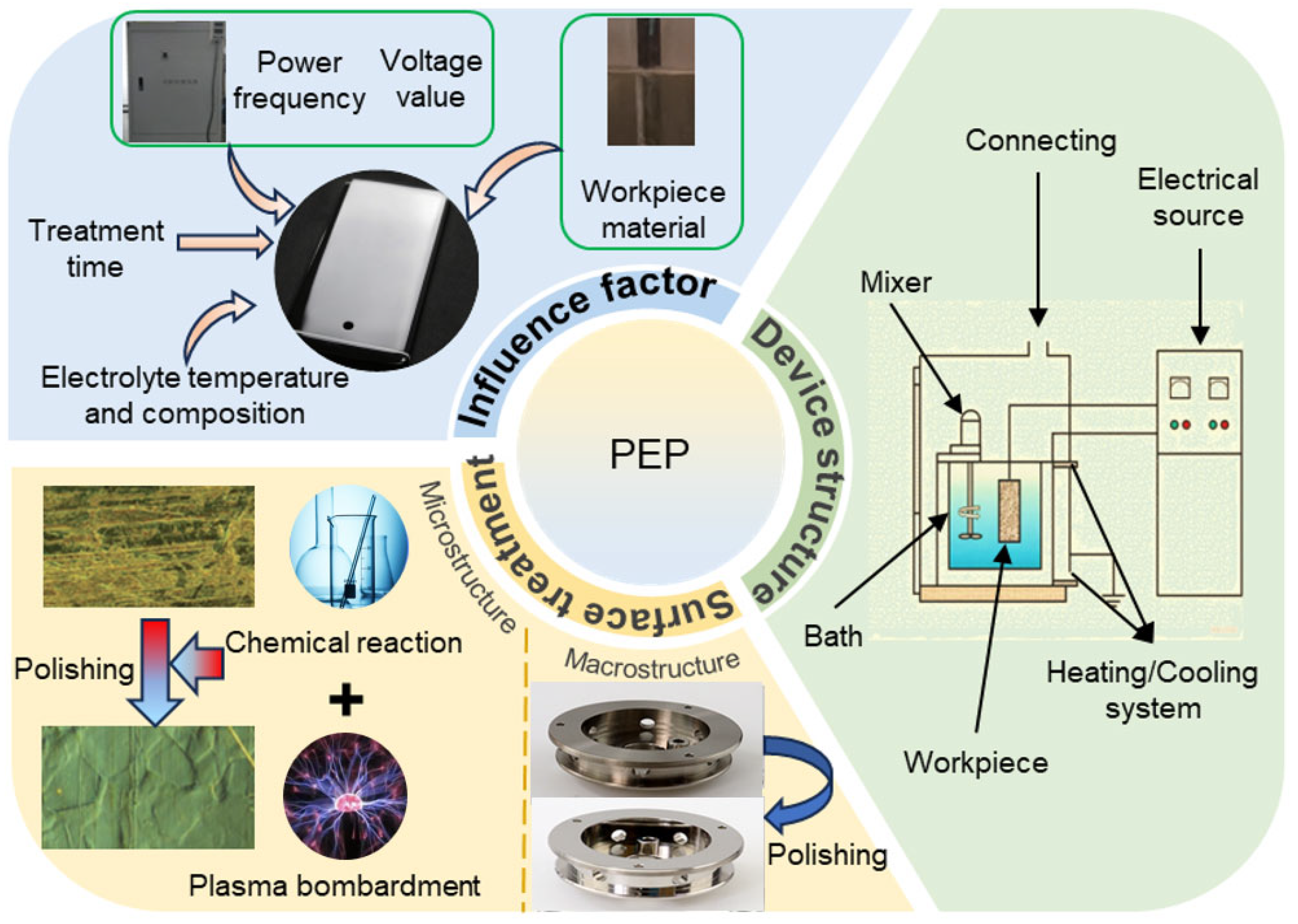
Figure 1. Plasma Electrolytic Polishing: Equipment, Surface treatment, and key factors influencing polishing quality.
Lubricants 13 00412 g001
Figure 2. (a) Global distribution and (b) annual trends of research publications on plasma electrolytic polishing (data source from the web of science).
Lubricants 13 00412 g002
Figure 3. Schematic representation of PEP equipment [10], copyright 2022, with permission from Wiley.
Lubricants 13 00412 g003
Figure 4. Typical current voltage relationship of PEP anode process [13], copyright 2015, with permission from International Scientific.
Lubricants 13 00412 g004
Figure 5. Illustrative diagram of plasma discharge, the blue dots are neutral particles and positive ions, and the red dots are electrons. (a) Generate plasma, (b) Formation of electron avalanche, (c) Plasma contact with substrate surface, (d) High temperature is generated at the contact point, (e) Plasma discharge channel, (f) Gas explosion [25], copyright 2017, with permission from MDPI.
Lubricants 13 00412 g005
Figure 6. The mechanism of electrolytic-plasma polishing [13], copyright 2015, with permission from International Scientific.
Lubricants 13 00412 g006
Figure 7. Effect factors of surface quality and material removal [9], copyright 2021, with permission from Springer Nature.
Lubricants 13 00412 g007
Figure 8. (a) Current-voltage characteristic of the passage of current through a solution of ammonium sulfate (5%) at its various temperatures, (b) Temperature-voltage characteristic of the passage of current through a solution of ammonium sulfate (5%) at its various temperatures [44], copyright 2019, with permission from IOP Publishing Ltd.
Lubricants 13 00412 g008
Figure 9. Copper alloy surface:(a) Unpolished, (b) Polishing for 15 s, (c) Polishing for 120 s [8], copyright 2016, with permission from Elsevier.
Lubricants 13 00412 g009
Figure 10. (a) Bronze valve before and after PEP [8], copyright 2016, with permission from Elsevier. (b) Titanium micro implant after milling (left) and after PEP (right) [31], copyright 2016, with permission from Elsevier. (c) WC hard alloy workpiece photo: as-received (left) and after PEP (right) [51], copyright 2021, with permission from Elsevier. (d) Examples of PEP products of alloy VT6 [52], copyright 2018, with permission from Science and Technique.
Lubricants 13 00412 g010
Figure 11. A cut tube with an unpolished and polished area (a): Illustrative diagram of the surface of unpolished (b) and polished areas (c) within the tube at a voltage of 320 V [25], copyright 2017, with permission from MDPI; Surface condition of the workpiece during PEP treatment: (d) the beginning shape of the surface; (e) the surface after 60 s of polishing; (f) the surface after 120 s of polishing; (g) the surface after 210 s of polishing; (h) the surface after 330 s of polishing; (i) the surface after 390 s of polishing [54], copyright 2018, with permission from Dspace.
Lubricants 13 00412 g011
Figure 12. Microstructure of Al-Si-Mg alloy components. (a,b) Before plasma electrolysis treatment, (c,d) After plasma electrolysis treatment [69], copyright 2018, with permission from Springer Nature.
Lubricants 13 00412 g012
Figure 13. SEM Images and Surface Morphology of Titanium Alloy at Different Polishing Stages: (a) As-built, (b) Sand blasted, (c) Sand Blasted + PEP, (d) Sand blasted + Vibratory Grounded + PEP [74], copyright 2021, with permission from Elsevier.
Lubricants 13 00412 g013
Figure 14. Copper surface morphology:(a,c) before PEP; (b,d) after PEP [86].
Lubricants 13 00412 g014
Figure 15. (a) SEM images of CoCr alloy after PEP; (b) Surface profile images of CoCr alloy after PEP [91], copyright 2021, with permission from Elsevier.
Lubricants 13 00412 g015
Figure 16. (a) Macro-morphologies of 6061 aluminum alloy before (left) and after polishing (right) [64], copyright 2024, with permission from Elsevier. (b) Samples surface after EPP and a voltage of 280 V (left) and 260 V (right) [76], copyright 2018, with permission from IOP Publishing Ltd. (c) Copper alloy workpieces before (left) and after polishing (right) [82], copyright 2015, with permission from IOP Publishing Ltd. (d) Copper plated carbon fiber woven fabric before (left) and after treatment (right) [85], copyright 2016, with permission from AIMS Press.
Lubricants 13 00412 g016
Figure 17. View of the samples which have been treated under different conditions [30], copyright 2001, with permission from Elsevier.
Lubricants 13 00412 g017
Figure 18. Topography of the surface: (a) initial state of the surface (TiN), (b) oxidized surface (High-Low, 30 s), (c) scratches freed from the coating (High-Low, 120 s), (d) pores freed from the coating (High-Low, 120 s), (e) polished surface freed from the coating (High-Low, 600 s) [30], copyright 2001, with permission from Elsevier.
Lubricants 13 00412 g018
Figure 19. Schematic of plasma electrolytic processing and mechanical polishing (PEP-MP) step [98], copyright 2021, with permission from MDPI.
Lubricants 13 00412 g019
Figure 20. The scanning electron microscopy (SEM) images of single-crystal 4H-SiC surface: (a) Chemical cleaned surface; (b) After plasma electrolytic processing for 30 s; (c) After HF etching for 10 min; (d) After mechanical polishing for 5 min [98], copyright 2021, with permission from MDPI.
Lubricants 13 00412 g020
Figure 21. CLSM images of unpolished and plasma polished surfaces: (a) unpolished surface (Sa = 0.726 µm); (b) plasma polished surface after tept = 13.33 s (Sa = 0.040 µm); (c) plasma polished surface after tept = 26.66 s (Sa = 0.024 µm); (d) plasma polished surface after tept = 40.00 s (Sa = 0.023 µm) [105], copyright 2018, with permission from MDPI.
Lubricants 13 00412 g021
Figure 22. Process of PEP: (a) unpolished, the color is transparent; (b) during polishing; (c) after polishing, precipitation for 5 min; (d) suction filtration of the polishing liquid; (e) collection of polishing liquid after suction filtration; (f) precipitation of filtrated polish [109], copyright 2022, with permission from MDPI.
Lubricants 13 00412 g022
Table 1. Comparison of six mainstream polishing methods.
MethodMechanismEfficiencyMachinable Workpiece ShapeEnvironmental Protection LevelEnergy Consumption
Mechanical polishingPlastic DeformationInferiorSimpleInferiorMedium
Chemical polishingChemical corrosionInferiorComplexInferiorInferior
Electrochemical polishingElectrochemical corrosionMediumComplexInferiorHigh
Abrasive jet polishingErosion, shearingInferiorComplexMediumMedium
Laser PolishingRemeltingInferiorComplexHighHigh
Plasma electrolytic polishingPlasma bombardmentPlasma bombardmentComplexHighHigh
Table 2. Advantages and Disadvantages of PEP Compared with Traditional Polishing Methods.
MethodAdvantageDisadvantage
Mechanical polishingLow costLow efficiency, high environmental impact
Chemical polishingHigh efficiency, low costPoor roughness, high environmental impact
Electrochemical polishingGood roughnessHigh environmental impact
Plasma electrolytic polishingGood roughness, low environmental impactHigh cost
Table 3. Comparison of Power Supply Modes in PEP.
MethodologyContinuous PowerPulsed Power
Surface RoughnessHigher RaLower Ra (down to nanometer scale)
Material Removal RateHighHigh
Thermal EffectHigh heat inputLower average thermal load
Energy ConsumptionHigh consumptionReduced by ~10–30%
Suitable MaterialsStainless steels, copper, and stable metalsTitanium alloys, aluminum alloys, difficult-to-machine materials
Application ScenariosModerate surface finishHigh-precision, complex parts
Table 4. Selection of Electrolytes and Optimal Parameter Ranges for PEP of Various Materials.
MaterialElectrolyte ComponentsU (V)T (°C)t (min)
Stainless steel2–6 wt% (NH4)2SO4260–32070–852–10
Aluminum alloys10% NH4Cl + 4% KCl + 3% H2C2O4, 2–4 wt% (NH4)2SO4240–32050–802–8
Titanium alloy(NH4)2SO4, NH4F, NaF230–33075–952–10
Copper alloys2–5 wt% (NH4)2SO4, NH4F, NH4NO3180–35060–903–6
Cemented carbide(NH4)2SO4, NaNO3, Na2CO3220–30070–902–5
non-metallic materials1% NaCl150–20020–4015–20
Table 5. The conditions for steel PEP and the results achieved therefrom.
Samples MaterialElectrolyte ComponentsU (V)T (°C)t (min)Ra (μm)Ref.
316L4% (NH4)2SO430080-8.54[55]
316L-370-2–600.18[57]
316L4% (NH4)2SO4 and 1% disodium ethylenediaminetetraacetate33085–900.5–41.4[58]
316L-35060–9010–900.1[59]
316L5% Na2CO3 or NaCl130-1-[60]
316L
304
4% (NH4)2SO4220–36080–905–100.09[61]
MS1(NH4)2SO4 and C6H8O7330–33870–90100.53[62]
MS1(NH4)2SO43508010–202.6[63]
Table 6. The conditions for aluminum alloy PEP and the results achieved therefrom.
Samples MaterialElectrolyte ComponentsU (V)T (°C)t (min)Ra (μm)Ref.
6061-3708040.138[64]
AlSi10Mg4% KCl and 2% C2H2O225070–8021.6[66]
Aluminum alloy10% NH4Cl, 4% KCl and 3% H2C2O430060–80-0.16[67]
AlSi10Mg7% NaCl400–50016–900.50.68[68]
D164–5% KNO3, 2–3% C6H8O7 and 0.5–1% glycerol280–320-20.2[69]
Table 7. The conditions for titanium alloy PEP and the results achieved therefrom.
Samples MaterialElectrolyte ComponentsU (V)T (°C)t (min)Ra (μm)Ref.
TC4-327–33775–9024–32<1[73]
TC42–5% (NH4)2SO4-9340.41[74]
Titanium alloy4% NH4F260–30075–951–50.1[53]
Titanium alloy1.5–3% NH4Cl and 1.25–2.75% NH4F-80–95-0.12[75]
TC44–6% NH2OH·HCl and 0.7–0.8% KF or NaF260–28085–952–100.04[76]
Table 8. The conditions for copper alloy PEP and the results achieved therefrom.
Samples MaterialElectrolyte ComponentsU (V)T (°C)t (min)Ra (μm)Ref.
Copper alloyC6H8O7180–3001202<0.02[8]
L63 brassNH4F and C6H5O7(NH4)3290–34060–9010–25 s0.05[81]
Copper-180–3003026.0[81]
copper M1NaCl, CuSO4, NH4NO3400–55080–12020–35 s0.08[82]
H62 brass--8050.176[83]
Red copper-26090110.064[84]
Table 9. The conditions for hard metal PEP and the results achieved therefrom.
Samples MaterialElectrolyte ComponentsU (V)T (°C)t (min)Ra (μm)Ref.
CoCr(NH4)2SO435070–8050.01[89]
CoCr5–15% (NH4)2SO440080-1.6[90]
WCNa2CO30–3007040–100 s0.08[51]
CoCr(NH4)2SO445075–8080.02[91]
CoCr4% (NH4)2SO4240–30070–900.5–2.50.057[92]
Table 10. Plasma polishing process of SiC.
Samples MaterialElectrolyte ComponentsU (V)T (°C)t (min)Ra (μm)Ref.
SiC1% NaCl200250.50.0081[98]
SiC0.5% NaCl300-5-[99]
SiC1% NaCl15025200.00046[100]
SiCH2O + 2% He--180-[101]
SiCHe + 3.73% H2O--60-[102]
Disclaimer/Publisher’s Note: The statements, opinions and data contained in all publications are solely those of the individual author(s) and contributor(s) and not of MDPI and/or the editor(s). MDPI and/or the editor(s) disclaim responsibility for any injury to people or property resulting from any ideas, methods, instructions or products referred to in the content.