Article

Modeling and Prediction of Tribological Performance of Surface Textures on Spherical Hydrostatic–Hydrodynamic Bearings

1
School of Mechanical Engineering, University of Shanghai for Science and Technology, Shanghai 200093, China
2
School of Intelligent Emergency Management, University of Shanghai for Science and Technology, Shanghai 200093, China
3
School of Mechanical Electronic Technology, Shanghai Jian Qiao University, Shanghai 201306, China
4
Merchant Marine College, Shanghai Maritime University, Shanghai 201306, China
*
Author to whom correspondence should be addressed.
Lubricants 2025, 13(9), 408; https://doi.org/10.3390/lubricants13090408
Submission received: 30 July 2025 / Revised: 1 September 2025 / Accepted: 9 September 2025 / Published: 12 September 2025
(This article belongs to the Special Issue Novel Tribology in Drivetrain Components)

Abstract

Spherical hydrostatic-hydrodynamic bearings (SHHBs) combine the advantages of hydrostatic and hydrodynamic lubrication. Endowed with the characteristics of withstanding heavy loads, reducing friction, and self-aligning, they are widely applied in high-precision machinery and extreme environment systems. However, current research on the impact of surface textures on bearing lubrication performance has predominantly concentrated on journal bearings, while systematic studies concerning textures for spherical bearings remain relatively inadequate. Therefore, this study developed a lubrication model for SHHBs, aiming to analyze the impact of surface textures on such bearings, with a specific focus on investigating the effects of circular and rectangular surface textures on the load-carrying capacity and friction force of SHHBs. The research results demonstrate that both shapes of surface textures can effectively improve the performance of SHHBs. Specifically, for rectangular surface textures, when r p = 3.0   m m ,   h ¯ p = 2.4 , the load-carrying capacity of the bearing is increased by 19.01 % . It is also revealed that for both shapes of surface textures, when ε = 0.4 ,   ω z = 1800   d e g / s , increasing the radial clearance leads to a reduction in the bearing’s load-carrying capacity. This work provides a theoretical foundation for designing advanced SHHBs with surface texturing.

1. Introduction

SHHBs that are characterized by low friction and high load-carrying capacity are widely used in rotating machinery to ensure efficient component operation [1]. Given their critical industrial importance, enhancing their performance has become a research priority. Surface texturing technology, emerging since the 1960s [2], has found engineering applications in journal bearings due to its ease of manufacturing and ability to significantly improve surface friction reduction and wear resistance.
In the field of conventional bearings, surface texturing has attracted considerable attention from researchers and yielded substantial research outcomes. Common surface textures include spherical, elliptical, circular, triangular, and V-shaped textures. Ji et al. [3] demonstrated that partial surface texturing with oriented elliptical dimples can enhance hydrodynamic lubrication in parallel infinite-width sliders. However, spherical dimples are more widely used [3,4] because their ease of manufacturing offers greater cost-effectiveness. Surface textures are classified into various types, such as protrusions, dimples, grooves, and hybrid structures [5]. Numerous studies have integrated surface textures with conventional bearings, leading to significant improvements in bearing performance. For instance, Gu et al. [6] found that under steady-state conditions, textures on the raceway effectively reduce friction. Kumar et al. [7] showed that low-density double triangular dimples reduce the friction coefficient and wear rate more significantly than circular dimples or double triangular dimples with a density of 20%. Tang et al. [8] investigated the frictional behavior of grease-lubricated spherical plain bearings under mixed lubrication conditions using an electro-hydraulic servo tribometer. Their results indicated that surface textures improve the frictional performance of the bearings; compared with non-textured samples, the maximum reduction in the friction coefficient of textured samples reached 55%.
Some scholars have also explored the mechanism by which texture characteristics influence bearing performance, providing a theoretical basis for bearing design and optimization. From the perspective of texture geometric parameters, Manser et al. [9] compared eight texture shapes and found that convergent wedge structures (e.g., T2 triangular textures) increase the load-carrying capacity by 22%, whereas divergent wedges result in a loss of load-carrying capacity. Hingawe and Bhore [10] demonstrated in parallel sliders with square textures that the T2 triangular bottom profile exhibits a significantly higher load-carrying capacity than planar textures. They also noted that flow rate is the main process parameter affecting performance, while the effect of texture density is relatively minor. Sharma’s [11] numerical study, which also focused on triangular textures, found that when the bearing has a low eccentricity ratio of 0.2 and a texture depth of 1.0, surface textures in the pressure-increasing region positively impact the bearing’s performance improvement rate, resulting in better load-carrying capacity and a lower friction coefficient compared with non-textured bearings. Additionally, in terms of parameter optimization and multi-physics field coupling, Yu et al. [12] investigated three-oil-wedge radial sliding bearings. They optimized the elliptical opening offset parabolic texture (EOOPT) using the response surface methodology, which led to a 13.7% increase in the bearing’s load-carrying pressure, a 13.8% reduction in the friction coefficient, and an 8.3% decrease in the average temperature. Gu et al. [13] proposed a multi-objective adaptive scale texture optimization method. Based on the cavitation effect and surface roughness, they established a mixed lubrication model and used the grey wolf optimization algorithm to solve for texture parameter combinations under different working conditions. Their findings indicated that adaptive scale-like textures significantly increase the minimum oil film thickness. Zhang et al. [14] developed a numerical model to calculate the friction coefficient and load-carrying capacity of textured journal bearings. They divided the sleeve surface into rectangular grids, marking the presence or absence of textures at the center of each grid with 1 and 0, respectively. By using genetic algorithms to evolve and select different arrangements of texture coverage areas, they ultimately improved the tribological properties of the journal bearings. Meanwhile, some studies have also found that there is a certain synergistic effect between texture performance and lubricating media. Dass et al. [15] used ferrofluid as a magnetic lubricant and found that textured surfaces increase the load-carrying capacity by 246% and improve pressure distribution by 165%. They also revealed the load-increasing mechanism resulting from the coupling effect between the magnetic medium and textures. Manser et al. [16] found that texturing in the convergent region of the bearing can compensate for performance degradation caused by elastic deformation and shear-thinning lubricants (with the load-carrying capacity increased by 10%). However, due to defects in texture arrangement, the particle swarm optimization algorithm is required to optimize the texture layout. Turali et al. [17] discussed the effect of MoS2 solid lubricant on reducing friction and wear in the friction pair consisting of Ti64 alloy and AISI 52100 steel. Their results showed that combining laser surface texturing (LST) with solid lubricant nanoparticles on Ti64 alloy extends the service life of friction-mating components.
Although surface texturing technology has been maturely applied in conventional bearings, research on SHHBs remains limited. This is primarily because the more complex structure and working principles of SHHBs increase the difficulty of texture design and implementation. Tomar et al. [18] studied the minimum film thickness, frictional torque, and flow rate of SHHBs, while Nitin Agrawal et al. [19] explored the performance of hybrid spherical thrust bearings in Newtonian and non-Newtonian fluids. However, accurately evaluating the performance of textured SHHBs remains a major challenge in current research.
To address lubrication challenges in SHHBs, this paper develops a dedicated lubrication model integrating bearing structural parameters and operating conditions. as shown in Figure 1. The model reveals the lubrication mechanism of textured surfaces through numerical simulations and theoretical analysis. It focuses on investigating the effects of circular/rectangular surface textures on bearing performance, validating the model’s effectiveness against theoretical values. Additionally, the optimization impacts of textured surfaces on load-carrying capacity under varying operational conditions are analyzed, providing theoretical support and practical guidance for SHHBs design optimization.

2. Mathematical Model

2.1. Bearing Geometry and Representation

In three-dimensional spatial analysis, the spherical coordinate system is highly valued for its unique advantages in describing rotational dynamics and simplifying mathematical expressions. Particularly in the fluid mechanics applications of SHHBs, the spherical coordinate system provides an efficient and concise analytical method for characterizing flow patterns around spherical geometries. The geometric symmetry of SHHBs closely aligns with that of the spherical coordinate system, making the study of SHHBs within this framework a more natural and efficient approach for analyzing their motion characteristics and performance.
The oil film thickness of SHHBs can be divided into textured and non-textured regions. The oil film thickness for non-textured SHHBs can be expressed as [19].
h φ , θ , t = c 1 ε x t s i n θ c o s φ ε y t s i n θ s i n φ ε z t c o s θ
where c is the radial clearance of SHHBs; ε x t , ε y t , ε z t is bearing center coordinates.
The dimensionless form of oil film thickness for the SHHBs without texture is represented as [19,20]:
h ¯ φ , θ , t = 1 ε x t s i n θ c o s φ ε y t s i n θ s i n φ ε z t c o s θ
The total normalized oil film thickness is represented as [19,20]:
h ¯ φ , θ , t = 1 ε ¯ x t s i n θ c o s φ ε ¯ y t s i n θ s i n φ ε ¯ z t c o s θ + h ¯ t e x t u r e
The additional oil film thickness at the textured area is denoted as h ¯ t e x t u r e . The detailed expression of the oil film thickness is presented in references [18,21].
As shown in Figure 1, the texture shapes are spherical and rectangular dimples. They can be characterized using a mathematical expression based on spherical coordinates, with the model constructed in terms of the polar angle ( θ = θ 1 ~ θ 2 ) and azimuthal angle ( φ = 0 ° ~ 360 ° ) , and oil grooves are set at specified locations.
h ¯ t e x t u r e = ε ¯ 2 δ ¯ + δ ¯ ζ ¯ 4 ε ¯ 2 ζ ¯ 2 x ¯ l 2 + z ¯ l 2 2 1 2 + ε ¯ 2 δ ¯ δ ¯ ζ ¯ 4 ε ¯             w h e n     x ¯ l 2 + z ¯ l 2 1 2 < 1 h ¯ t e x t u r e = 0                                                                                                                                                                   w h e n     x ¯ l 2 + z ¯ l 2 1 2 1  
where ε ¯ is Pit aspect ratio; δ ¯ is normalized clearance; ζ ¯ is the ratio of the texture radius to the spherical bearing radius. x l , z l is in the local Cartesian coordinate system.
The oil film thickness for rectangular texture is represented as [18]:
h ¯ t e x t u r e = h p c
The dimensionless parameters are defined as follows [18,19]:
ε ¯ = h p 2 r p ;       δ ¯ = c 2 r p ;       ζ ¯ = r p R ;       x ¯ l = x l r p ;       z ¯ l = z l r p
where h p is texture depth and r p is texture radius.

2.2. Lubrication Model

In order to study the lubrication performance of SHHBs, the Reynolds equation in the conventional Cartesian coordinate system needs to be transformed into the Reynolds equation in the spherical coordinate system. The SHHBs under study is shown in Figure 1. The pressure at the oil supply port remains constant. It is assumed here that the lubricant is in a steady-state, laminar, isothermal, and incompressible condition, so the Reynolds equation can be simplified as [18,22,23,24].
1 R 2 1 s i n θ θ h 3 12 μ s i n θ p θ + 1 s i n 2 θ φ h 3 12 μ p φ = ω j 2 h φ + h t
To reduce computational numerical loss, some parameters are normalized [18,19].
μ ¯ = μ μ r ;       p ¯ = p p s ;       h ¯ = h c ;       Ω = ω j c 2 p s μ R 2 ;       t ¯ = t μ R 2 c 2 p s  
where μ is lubricant viscosity; p s is oil supply pressure; ω j is shaft speed.
The dimensionless form is represented as [18,19]:
1 s i n θ θ h ¯ 3 12 μ ¯ s i n θ p ¯ θ + 1 s i n 2 θ φ h ¯ 3 12 μ ¯ p ¯ φ = ω j 2 h ¯ φ + h ¯ t ¯  

2.3. The Load Carrying Capacity of SHHBs

The most important factor in estimating the bearing’s service life is calculating the load carrying capacity. The formula can be expressed as [20].
L C C x = R 2 φ 1 φ 2 θ 1 θ 2 p sin θ cos φ sin θ d θ d φ L C C y = R 2 φ 1 φ 2 θ 1 θ 2 p sin θ sin φ sin θ d θ d φ L C C z = R 2 φ 1 φ 2 θ 1 θ 2 p cos θ sin θ d θ d φ                    
L C C = L C C x 2 + L C C y 2 + L C C z 2 1 2

2.4. Friction

The frictional torque can be obtained by the following expression [20]
T x T y T z = S f 0 τ θ r sin φ + τ φ r cos φ cos θ τ θ r cos φ + τ φ r sin φ cos θ τ φ r sin φ R 3 sin θ d θ d φ + S b 0 p f r o x κ x r o y κ y r o z κ z R 2 d θ d φ
where S f refers to the lubrication regime of the entire spherical region, while S b refers to the lubrication regime of the contact area. τ θ r ; τ φ r is fluid shear stress.
Frictional force can be calculated by [20]:
F = T R

3. Numerical Simulation Procedure

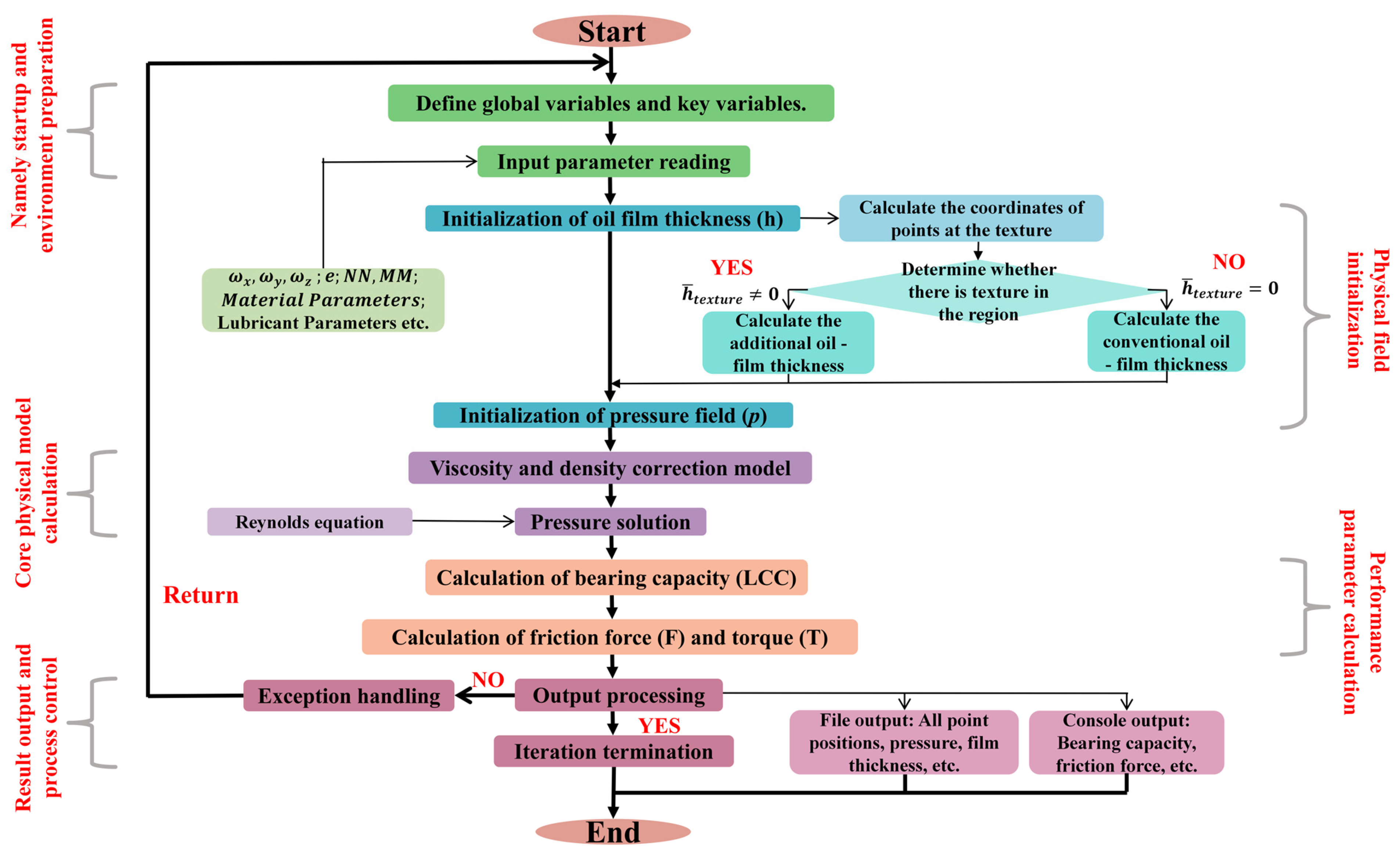
In this study, the lubrication model is discretized using the Finite Volume Method (FVM). The computational solution is implemented through Fortran programming, and the relevant results are finally obtained. The computational flow chart is shown in Figure 2. The sequence of computation is divided into five parts, namely startup and environment preparation, physical field initialization, core physical model calculation, performance parameter calculation, result output and process control. These parts are used to calculate and solve parameters such as load carrying capacity, friction force and pressure at each point of the bearing. Figure 3, on the other hand, presents the theoretical schematic diagram of the SHHBs as well as the referenced three-dimensional coordinate system. This paper focuses on the bearing component illustrated in the theoretical schematic diagram presented in Figure 3, with a particular focus on the effects of textures and their parameters on SHHBs.
For the sake of simplicity, this paper only briefly presents the essential information of the model. For detailed information, the readers can refer to the work by Wang et al. [25].

3.1. Mesh Sensitivity Test

It is noteworthy that the geometric configuration of a SHHB can be inherently characterized within a spherical coordinate system, as schematically presented in Figure 4a. Specifically, the adopted spherical coordinate system must align with the modeling specifications of spherical bearings, which is essential for the accurate resolution of tribological issues. Given that numerical methodologies serve as the primary approach for addressing the majority of tribological problems associated with spherical bearings, the geometric features of the bearing are discretized within the framework of a spherical mesh-grid space. This discrete representation is constructed on the basis of a foundational spherical bearing geometry model; consequently, the computational framework employed for solving tribological problems of spherical bearings is commonly designated as the spherical-grid-data model (SGDM) [26].
For modeling a SHHB, its geometry is meshed using spherical coordinates ( φ , θ ) , with corresponding coordinate increments ( Δ φ , Δ θ ) , as shown in Figure 4a. As depicted in Figure 4a, the position of a point S on the bearing surface is defined by its spherical coordinates ( R , φ , θ ) .
The modeling of SHHB-related problems exhibits a strong dependence on mesh grid density. Here, MM and NN denote the number of mesh nodes along the latitudinal and longitudinal directions of the lubricating film region, respectively, resulting in a total of MM×NN elements. The coordinate increments ( Δ φ , Δ θ ) can be calculated as follows:
Δ φ = φ 1 φ 2 M M 1 ,   Δ θ = θ 1 θ 2 N N 1
where φ1 and φ2 denote the starting and ending angles in the latitudinal direction, while θ1 and θ2 represent the starting and ending angles in the longitudinal direction. The basic parameters of the bearing are listed in Table 1. To obtain the optimal mesh parameter values under comprehensive conditions, different values have been set to evaluate the differences in load-carrying capacity, with specific values shown in Figure 4b. In total, 21 groups of data were tested, and the selection of the number of grids followed the rule that ( MM     1 )   =   4 ( NN     1 ) with the maximum number of meshes set to n m a x = NN × MM = 238 × 949 = 225,862 . The mesh numbers for the remaining groups were denoted as n i , and the corresponding mesh deviation rates q i were calculated.
q i = ( n i n m a x ) n m a x × 100 %
According to the results shown in Figure 4b, the mesh quantity of 172,432 (208 × 829) was selected as the optimal mesh for the numerical simulation.
In addition, the pressure boundary conditions were employed as follows: for the outlet boundary, the pressure is set to 0 MPa; for the oil supply inlet area, this paper adopts a constant-pressure oil supply method, where the flow rate is adjusted adaptively. The oil supply pressure is artificially imposed based on experimental experience, and the oil supply pressure used in this paper is 13.2 MPa. For the cavitation boundary, the well-known Reynolds cavitation boundary condition was adopted [26]. The mathematical model of the pressure gradient at this cavitation interface can be described as follows:
p θ =   p φ = 0

3.2. Numerical Simulation Validation

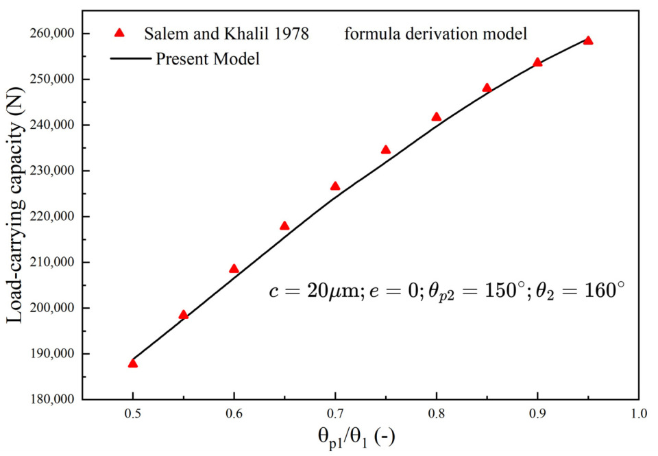
To verify the accuracy of the model built using Fortran, this paper validates the load-carrying capacity of the model.
The load-carrying capacity calculated by the model in this paper is validated against that computed using the load-carrying capacity formula derived by [27] et al. The validation results show a high degree of agreement in the magnitude of load-carrying capacity under different angle ratios. Therefore, the accuracy of the developed model can be confirmed, as show in Figure 5.

4. Results and Discussion of Numerical Calculations

4.1. Influence of Texture Parameters

This paper investigates the effects of the intrinsic parameters of two types of textures, namely the radius (half of the side length) and dimensionless depth of circular and rectangular textures, on the load-carrying capacity or friction force of SHHBs.

4.1.1. Effect of Dimensionless Depth of Textures

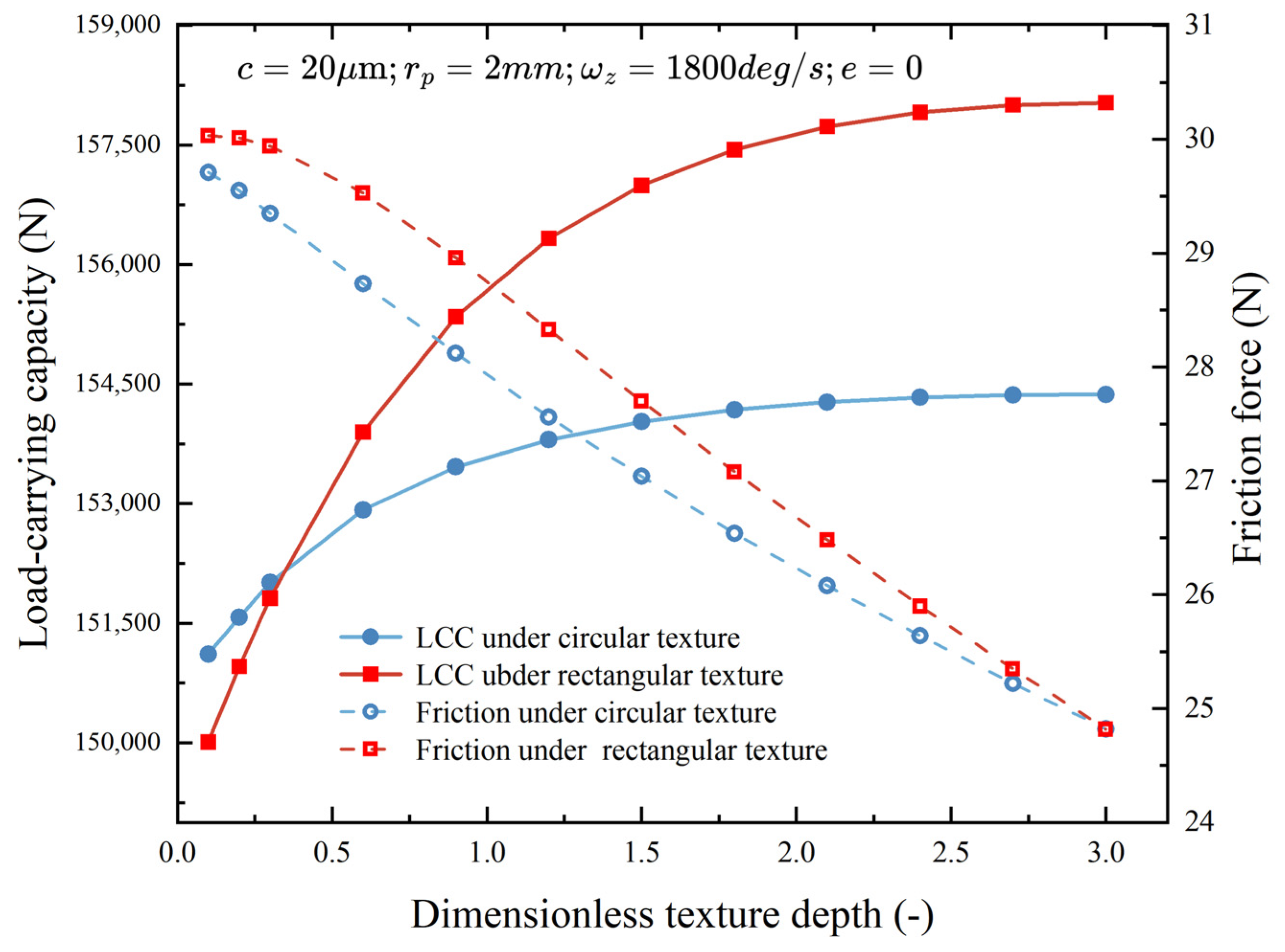
As illustrated in Figure 6, the fundamental parameters of the bearing are presented in Table 1. When the dimensionless depth h ¯ p of the two texture geometries is gradually increased, it can be observed that the load-carrying capacity tends to plateau starting from h ¯ p = 2.4 . For h ¯ p < 0.3 , the load-carrying capacity of the circular texture exceeds that of the rectangular texture; under all other conditions, the rectangular texture exhibits a higher load-carrying capacity than the circular counterpart. With respect to the friction force, it demonstrates a gradual decreasing trend as h ¯ p increases.

4.1.2. Effect of Texture Size

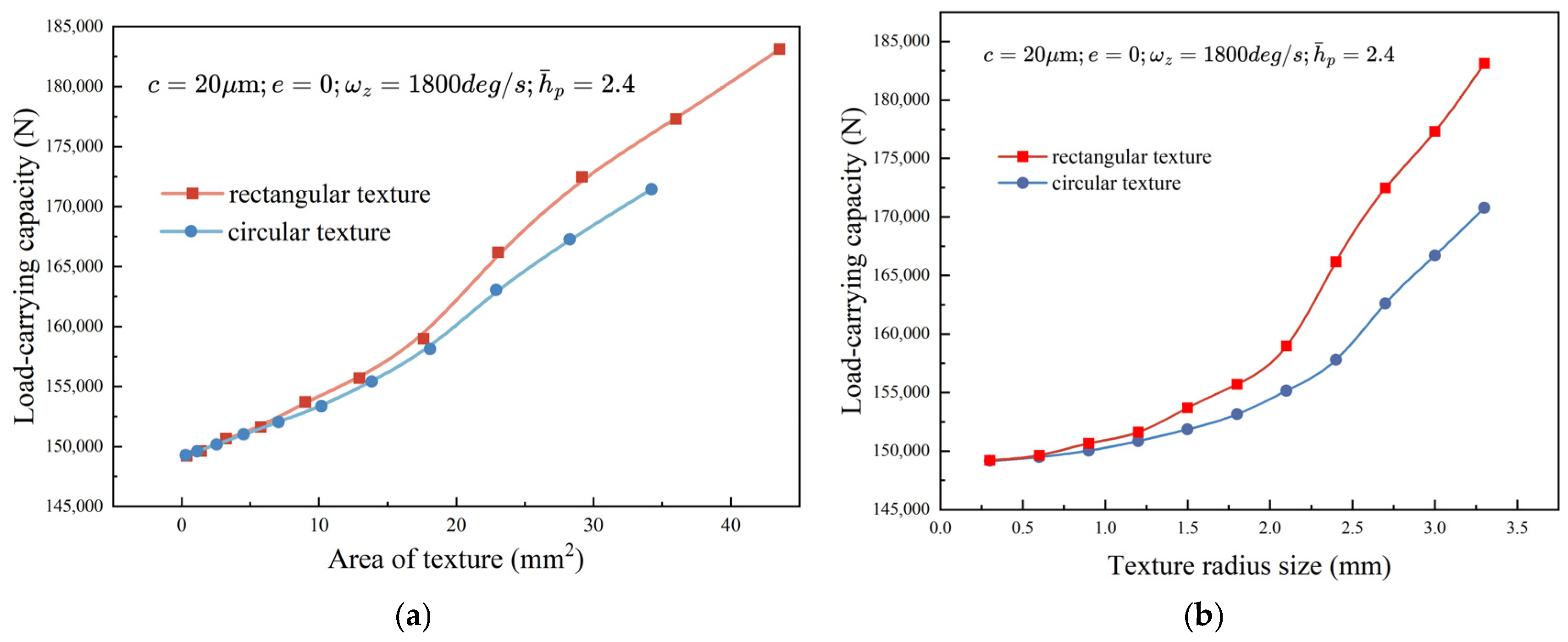
As shown in Figure 7a, the basic parameters of the bearing are listed in Table 1. With the dimensionless depth h ¯ p fixed at 2.4, as the texture radius is gradually increased, the load-carrying capacity of SHHBs increases progressively, and the rate of increase tends to accelerate. Moreover, within this range, the load-carrying capacity of square textures is greater than that of circular textures.
However, considering that when the circular texture and the rectangular texture have the same diameter or side length, the area of the rectangular texture is 27.32% larger than that of the circular texture, a comparison was made between the load-carrying capacities of the two textures under different areas. The results are shown in Figure 7b. When the area of the texture is larger than 5 mm2, the load-carrying capacity of the rectangular texture is also greater than that of the circular texture under the condition of the same texture area. Nevertheless, to reduce the complexity of calculations in this paper, the subsequent calculations will still take the radius of the texture or half of the side length as the main parameters.

4.2. Effect of Radial Clearance

This paper examines the effect of radial clearance values on the load-carrying capacity and friction force of the bearing under three different h ¯ p ratios, with fixed eccentricity and bearing rotational speed. The basic parameters of the bearing are listed in Table 1.
The results data regarding the influence on load-carrying capacity are presented in Figure 8a. From the perspective of h ¯ p , as h ¯ p decreases, the load-carrying capacity of the bearing gradually decreases, and when h ¯ p = 0.1 , the load-carrying capacity of the bearing approaches that of the SHHB without textures. Additionally, under the conditions of the two texture shapes and three dimensionless depth–diameter ratios, the load-carrying capacity of the bearing gradually decreases with the increase of radial clearance c . When the radial clearance c = 28   μ m , the load-carrying capacity decreases significantly. This could be attributed to the fact that when the radial clearance increases beyond a certain value, the thickness of the lubricating film will also exceed the critical range, which weakens the shearing and squeezing effects of the fluid flowing in the clearance, thereby failing to form a sufficient pressure field. This leads to a sharp decrease in the load-carrying capacity of the lubricating film as the film thickness increases. Furthermore, this is consistent with the law stated in the Reynolds equation that “the pressure gradient is inversely proportional to the cube of the film thickness” (excessively large film thickness results in a significant reduction in the pressure gradient). The load-carrying capacity of SHHBs with rectangular textures is greater than that of SHHBs with circular textures.
The influence on friction force is illustrated in Figure 8b. Within the range of radial clearance c from 10 to 30 μ m , under the conditions of three dimensionless depth–diameter ratios, the friction force of SHHBs with rectangular textures is consistently greater than that of SHHBs with circular textures. When h ¯ p = 2.4 , the minimum value occurs at c = 22   μ m , with the friction force first decreasing significantly and then increasing slowly. When h ¯ p = 1.2 , the minimum value appears at c = 16   μ m , and the friction force exhibits a wave-like variation trend, i.e., decreasing first, then increasing, and then decreasing again. The case when h ¯ p = 0.1 is similar to that of the friction force without textures: both show a trend of first increasing and then decreasing, with the maximum friction force occurring at c = 26   μ m and the minimum at c = 10   μ m .

4.3. Effect of Eccentricity

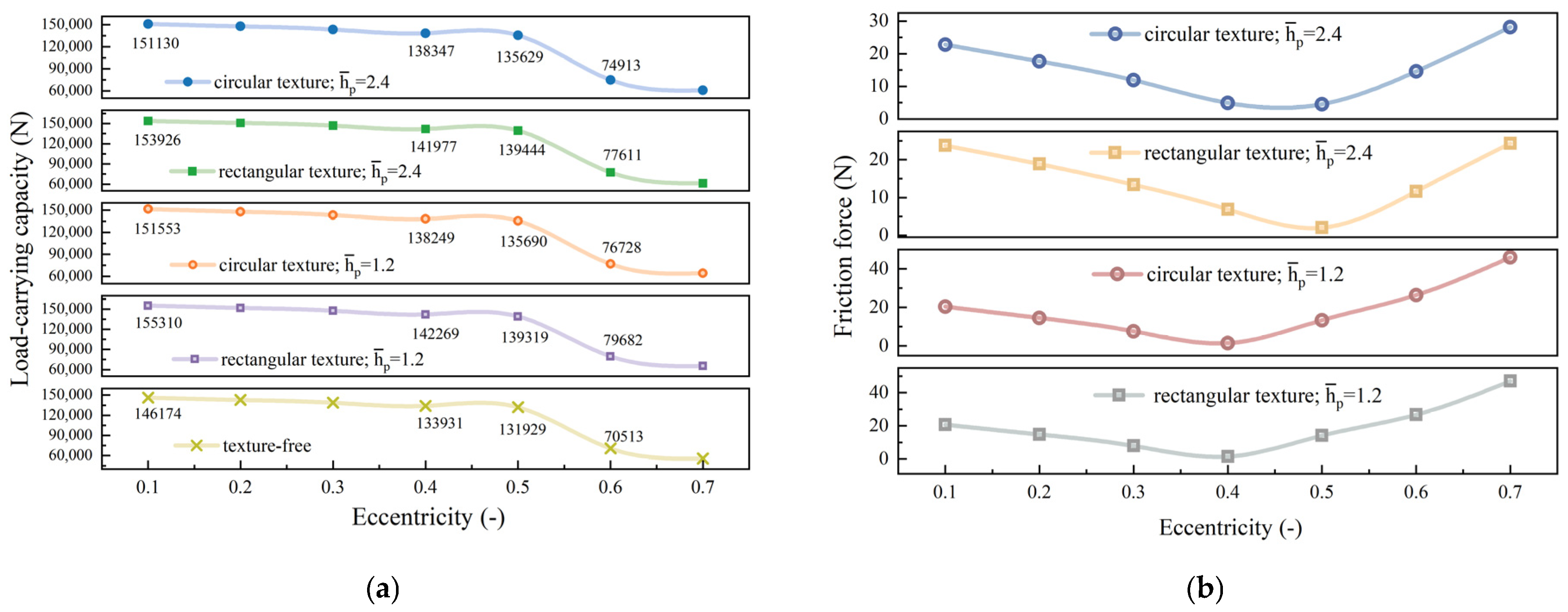
This paper also considers the influence of radial clearance values on the bearing’s load-carrying capacity and friction force under two different h ¯ p ratios, with the radial clearance c fixed at 20   μ m and the bearing rotational speed set to a specific value. The basic parameters of the bearing are listed in Table 1.
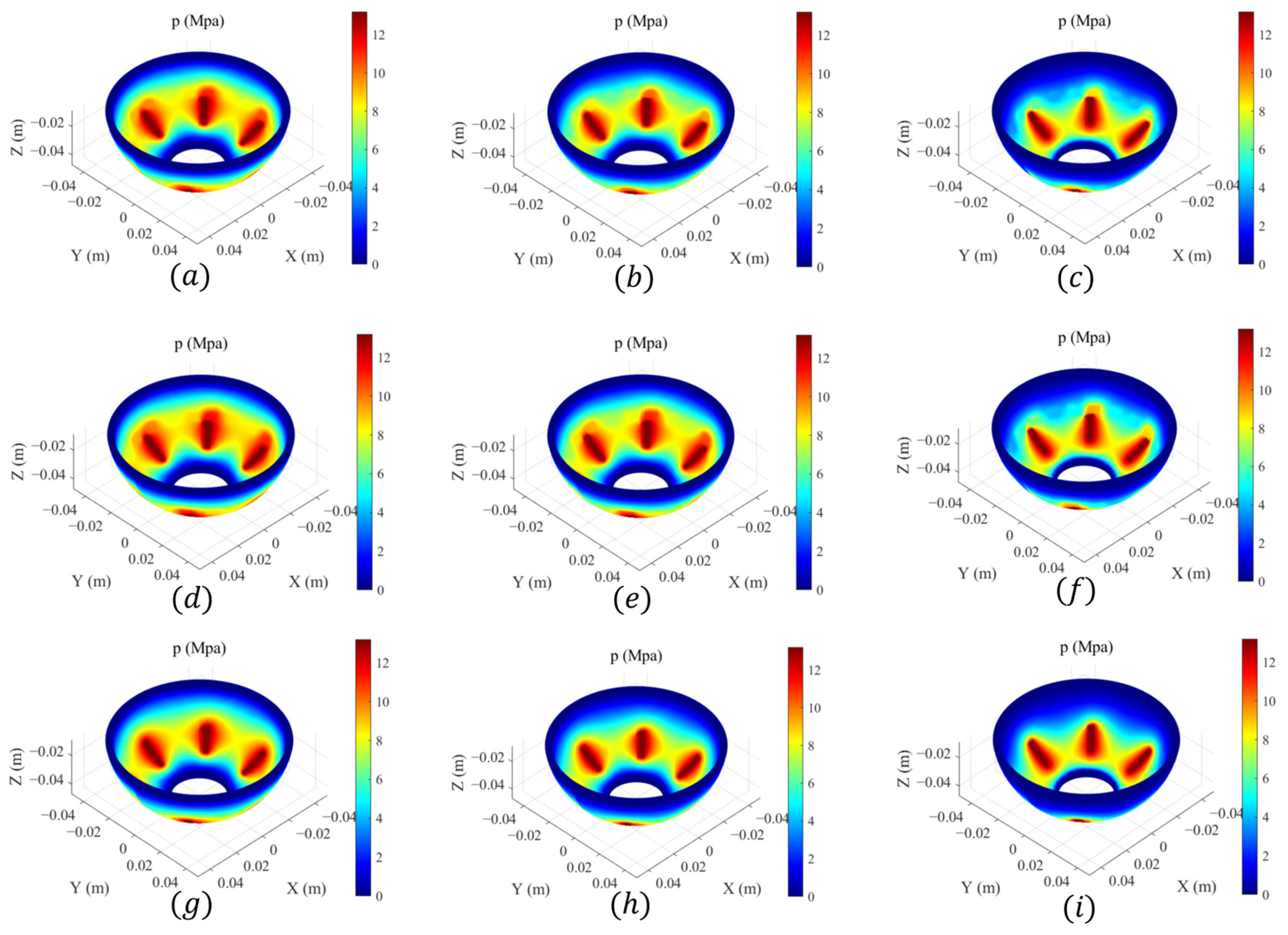
Figure 9 shows the pressure contours of textured and texture-free SHHBs under different eccentricities under the conditions given in Table 1.
The results for load-carrying capacity are presented in Figure 10a. Under both textured and non-textured conditions, the load-carrying capacity of SHHBs exhibits the same trend, i.e., an overall decreasing tendency. Before the eccentricity ϵ reaches 0.5, the load-carrying capacity first decreases; when the eccentricity ϵ equals 0.5, there is a slight increase in the load-carrying capacity. However, as the eccentricity continues to increase thereafter, the bearing’s load-carrying capacity drops sharply, a possible reason for this phenomenon is that high eccentricity violates the laminar flow assumption of the Reynolds equation, thereby rendering the equation inapplicable. At this point, the influence of different depth–diameter ratios on the load-carrying capacity is negligible for textures of the same shape. Moreover, the load-carrying capacity of SHHBs with rectangular textures is greater than that with circular textures, which in turn is greater than that of non-textured SHHBs.
The results of the friction force are presented in Figure 10b. Under the two conditions of dimensionless depth, the variation trend of the friction force of SHHBs is similar: it first decreases and then increases as the eccentricity increases. In the figure, when h ¯ p = 2.4 , the minimum friction force occurs at an eccentricity ϵ of 0.4; when h ¯ p = 1.2 , the minimum friction force occurs at an eccentricity ϵ of 0.5. The friction force of SHHBs with rectangular textures is greater than that of SHHBs with circular textures.

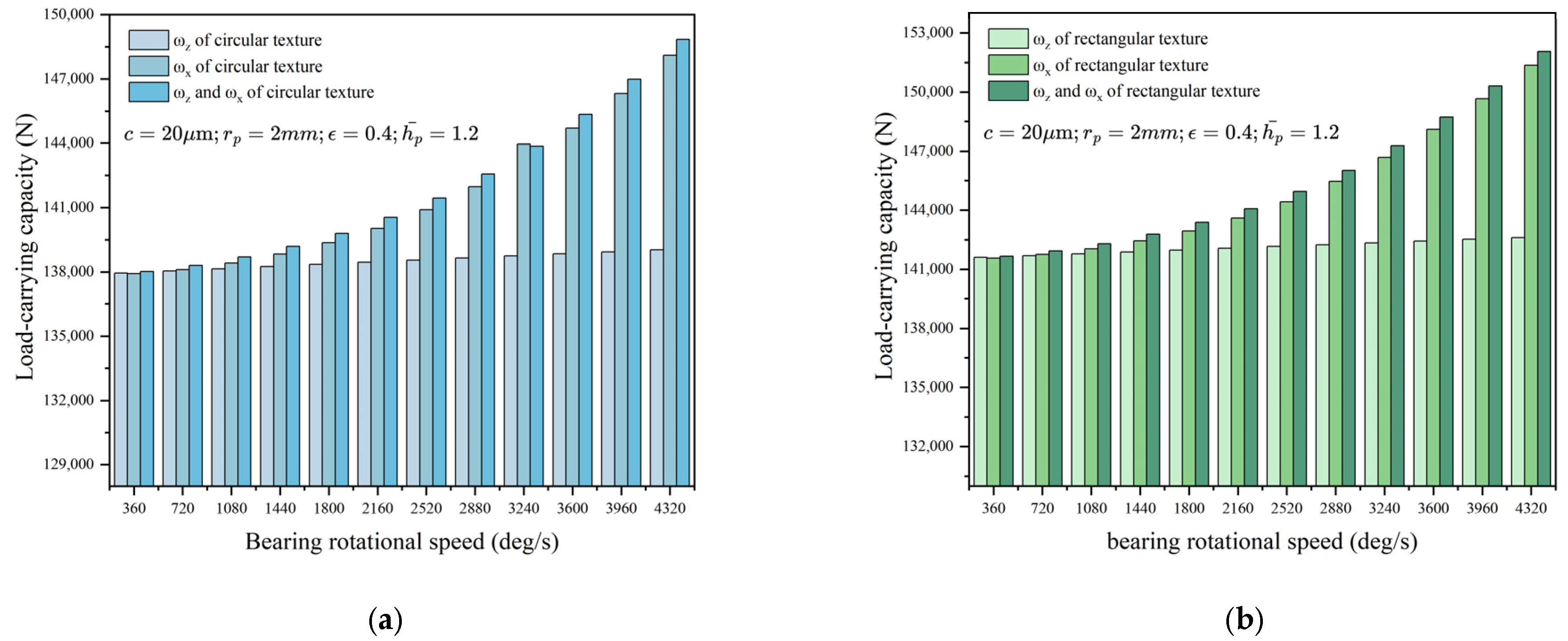
4.4. Effect of Rotational Speed

Figure 11 respectively analyzes the variation law of the load-carrying capacity of SHHBs under two texture conditions when the eccentricity and radial clearance are both fixed at h ¯ p = 2.4 , with the basic parameters of the bearing listed in Table 1. Twelve sets of data were set for the rotational speed within the range from 360   deg / s to 4320   deg / s , and the influence of rotational speed directions (x-direction, z-direction, and simultaneous x & z directions) on the bearing’s load-carrying capacity was comprehensively considered. The results show that increasing the rotational speed of the bearing can enhance the load-carrying capacity of SHHBs. As shown in Figure 11a,b, the influence of rotational speed on both textures is more significant in the x-axis direction than in the z-axis direction, and the load-carrying capacity increases more rapidly as the rotational speed increases. A possible reason for the more significant influence of the rotational speed around the x-axis (radial axis) is the “asymmetric wedge effect” generated in the spherical clearance [28]. Specifically, the lubricating film is strongly squeezed in a certain quadrant to form a converging clearance, while a diverging clearance is formed in the opposite quadrant. This makes the high-pressure region along the x-axis more prominent, directly enhancing the pressure component along the load direction in this axis, thus contributing more to the load-carrying capacity in this direction.

4.5. Effect of Outlet Angle

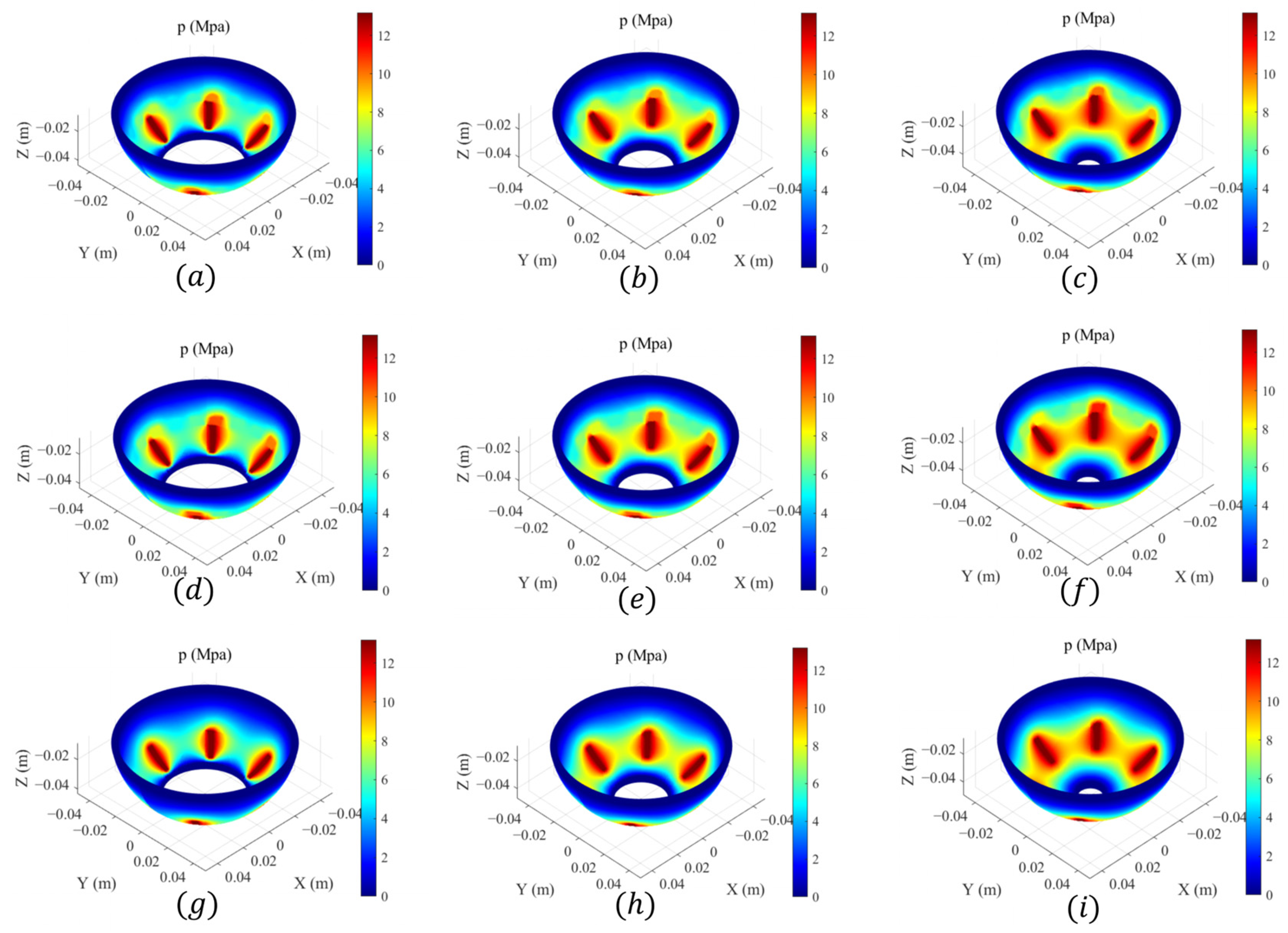
Figure 12 shows the pressure contours of textured and texture-free SHHBs when only the oil port angle values in Table 1 are changed.
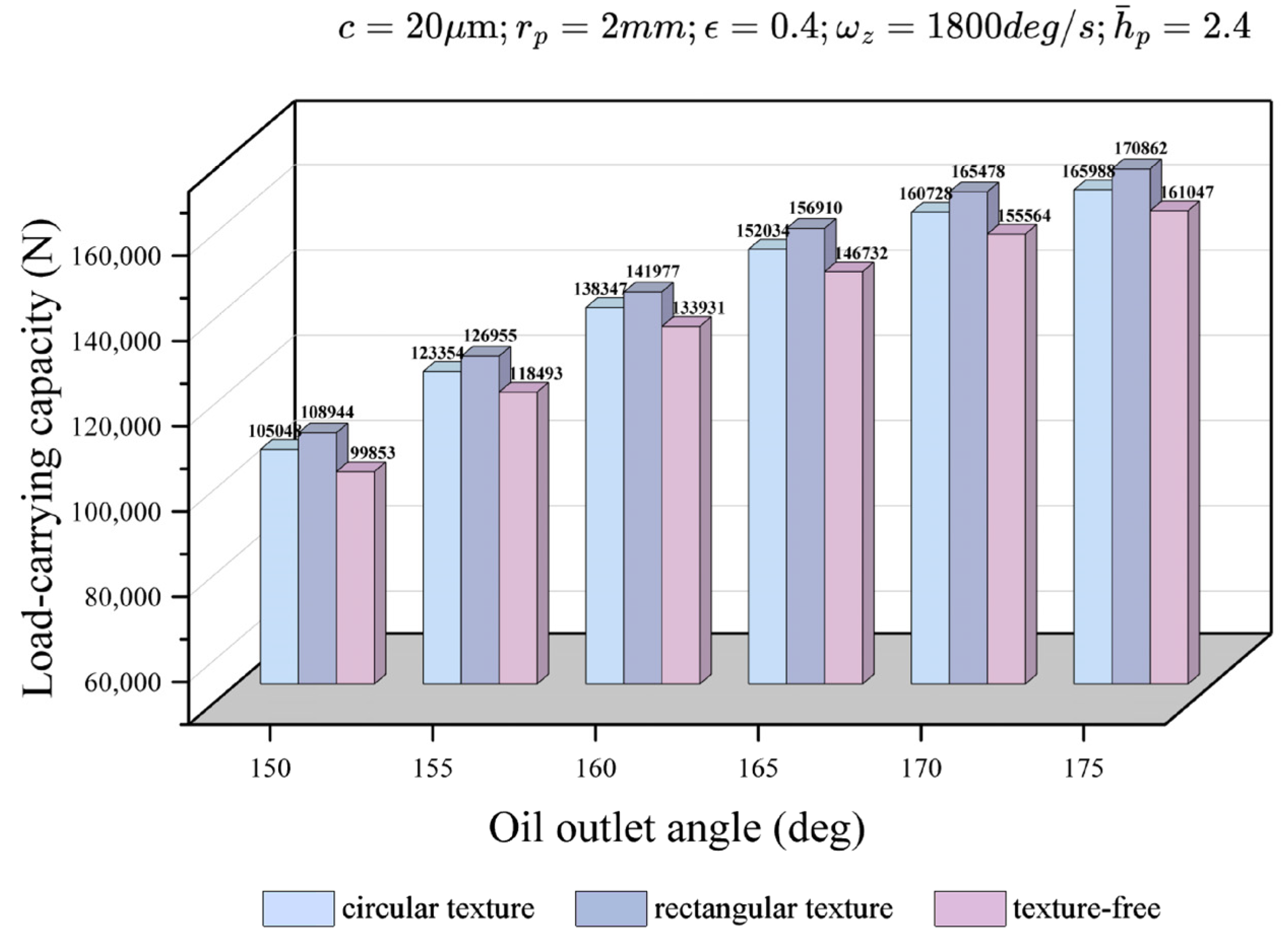
When h ¯ p = 2.4 , with eccentricity, radial clearance, and bearing rotational speed all fixed, and only the oil outlet angle of the bearing changed (as shown in Figure 13), it can be observed that the load-carrying capacity of the bearing gradually increases with the increase of radial clearance, and the increase in load-carrying capacity gradually becomes flattened. It may be because increasing the oil outlet angle enlarges the effective acting area of SHHBs, thereby further enhancing the load-carrying capacity. Meanwhile, the load-carrying capacity of SHHBs with rectangular textures is greater than that of SHHBs with circular textures, which in turn is greater than that of non-textured SHHBs.

5. Conclusions

The article summarizes the following rules by varying parameters such as texture parameters, eccentricity, radial clearance, rotational speed, and the angle of the oil outlet.
  • The presence of textures can improve the load-carrying capacity of the bearing, and the larger the texture radius, the better the load-carrying capacity. When the texture radius is fixed and the dimensionless depth of the texture is changed, the load-carrying capacity of SHHBs tends to be stable when h ¯ p = 2.4 .
  • Under certain conditions, when only the radial clearance is changed, the load-carrying capacity of the bearing decreases sharply when the radial clearance reaches 28   μ m , which is 60% lower than that when the radial clearance is 10   μ m .
  • To reduce the friction force during bearing operation, different radial clearances should be selected for different dimensionless depths. There exists such a rule: the minimum friction force obtained under different radial clearances corresponds to a decreasing radial clearance value as the dimensionless depth decreases.
  • Under certain conditions, when only the eccentricity is changed, the load-carrying capacity of SHHBs drops to 50% of that when the eccentricity ϵ is 0.1, when the eccentricity ϵ equals 0.6. Considering both friction force and load-carrying capacity, the eccentricity ϵ should be set within 0.5.
  • The load-carrying capacity of SHHBs gradually increases with the increase of rotational speed, and the influence of rotational speed in the x-axis direction on the bearing’s load-carrying capacity is greater than that in the z-axis direction.
  • As the oil outlet angle increases, the effective contact area between SHHBs and the rotor increases, and the load-carrying capacity of the bearing also increases gradually.

Author Contributions

Conceptualization, C.G. and H.X.; methodology, C.G. and H.X.; validation, H.X.; formal analysis, H.X.; investigation, H.X.; resources, C.G.; data curation, C.G.; writing—original draft preparation, H.X.; writing—review and editing, C.G. and D.Z.; visualization, H.X.; supervision, C.G.; project administration, C.G. and D.Z.; funding acquisition, C.G. All authors have read and agreed to the published version of the manuscript.

Funding

This work was funded by the National Natural Science Foundation of China, grant number 52305207.

Data Availability Statement

The data used to support the findings of this study are available from the corresponding author upon request.

Conflicts of Interest

The authors declare no conflicts of interest.

Nomenclature

R Bearing radius Ω Normalized shaft speed
h film thickness L C C Total bearing load-carrying capacity
θ Polar angle r o x , r o y , r o z Contact stress arm length of pits and peaks
φ Azimuthal angle f Coefficient of friction
p Fluid pressure T x , T y , T z Frictional torque in x , y , z directions
t Time F Total frictional force
p s Oil supply pressure τ θ r , τ φ r Fluid shear stress
μ Lubricant viscosity h ¯ Normalized film thickness
h p Pit depth ω x , ω y , ω z Bearing rotational speed in x , y , z directions
r p Pit radius h ¯ t e x t u r e Normalized texture film thickness
ε ¯ Pit aspect ratio x ¯ l , z ¯ l Normalized local Cartesian coordinate system
δ ¯ Normalized clearance ε x , ε y , ε z Bearing center coordinates
c Radial clearance p ¯ Normalized film pressure
φ i i Oil outlet width x p , y p , z p coordinate of the center of a single texture
T Synthetic torque ε ¯ x , ε ¯ y , ε ¯ z Normalized bearing center coordinates
ω j Shaft speed x l , z l Local Cartesian coordinate system
p Film pressure L C C x , L C C y , L C C z Load-carrying capacity in x , y , z directions

References

  1. Gao, W.; Li, Y.; Li, C.; Xu, Y.; Liu, Z. Numerical prediction of drag force on spherical elements inside high-speed ball bearing with under-race lubrication. Mech. Syst. Signal Process. 2025, 224, 112024. [Google Scholar] [CrossRef]
  2. Puoza, J.C. Research progress of surface texturing and thermal diffusion technology to improve tribological properties of materials. Prog. Eng. Sci. 2025, 2, 100034. [Google Scholar] [CrossRef]
  3. Ji, J.; Fu, Y.; Bi, Q. The influence of partially textured slider with orientation ellipse dimples on the behavior of hydrodynamic lubrication. Ind. Lubr. Tribol. 2014, 66, 161–167. [Google Scholar] [CrossRef]
  4. Qiu, M.; Delic, A.; Raeymaekers, B. The effect of texture shape on the load-carrying capacity of gas-lubricated parallel slider bearings. Tribol. Lett. 2012, 48, 315–327. [Google Scholar] [CrossRef]
  5. Huang, Y.-L.; Zhong, L.; Wang, G.-R.; Wei, G.; Peng, S.-C. Research status and progress of surface texture lubrication and friction reduction. Surf. Technol. 2021, 50, 217–232. [Google Scholar] [CrossRef]
  6. Gu, C.; Meng, X.; Xie, Y.; Yang, Y. Effects of surface texturing on ring/liner friction under starved lubrication. Tribol. Int. 2016, 94, 591–605. [Google Scholar] [CrossRef]
  7. Kumar, M.; Tyagi, R. Tribological performance of bearing steel with bi-triangular and circular textures under lubricated sliding. J. Mater. Eng. Perform. 2022, 31, 4519–4530. [Google Scholar] [CrossRef]
  8. Tang, Z.; Liu, X.; Liu, K. Effect of surface texture on the frictional properties of grease lubricated spherical plain bearings under reciprocating swing conditions. Proc. Inst. Mech. Eng. Part J J. Eng. Tribol. 2017, 231, 125–135. [Google Scholar] [CrossRef]
  9. Manser, B.; Belaidi, I.; Hamrani, A.; Khelladi, S.; Bakir, F. Texture shape effects on hydrodynamic journal bearing performances using mass-conserving numerical approach. Tribol.—Mater. Surf. Interfaces 2019, 14, 33–50. [Google Scholar] [CrossRef]
  10. Hingawe, N.D.; Bhore, S.P. Multi-objective optimization of the design parameters of texture bottom profiles in a parallel slider. Friction 2020, 8, 726–745. [Google Scholar] [CrossRef]
  11. Sharma, S. Lubrication characteristics of Newtonian-lubricated hydrodynamic bearing with partial and fully textured surface. In Machines, Mechanism and Robotics; Kumar, R., Chauhan, V.S., Talha, M., Pathak, H., Eds.; Springer: Singapore, 2022; pp. 1635–1643. [Google Scholar] [CrossRef]
  12. Yu, Y.; Zhou, L.; Ruan, W.; Xu, P.; Shen, J. Characteristic analysis and optimization of special-shaped micro-textured multi-oil wedge sliding bearing. J. Northwestern Polytech. Univ. 2023, 41, 222–229. [Google Scholar] [CrossRef]
  13. Gu, C.; Cui, Y.; Zhang, D. Research on the optimal design approach of the surface texture for journal bearings. Lubricants 2024, 12, 111. [Google Scholar] [CrossRef]
  14. Zhang, H.; Hafezi, M.; Dong, G.; Liu, Y. A design of coverage area for textured surface of sliding journal bearing based on genetic algorithm. J. Tribol. 2018, 140, 061702. [Google Scholar] [CrossRef]
  15. Dass, T.D.; Gunakala, S.R.; Comissiong, D.; Azamathulla, H.M.; Martin, H.; Ramachandran, S. Investigating journal bearing characteristics incorporating variable viscosity, couple-stress lubricant, slip-velocity, magnetic fluid, and sinusoidal surface-texturing. Results Eng. 2024, 22, 102338. [Google Scholar] [CrossRef]
  16. Manser, B.; Khelladi, S.; Deligant, M.; Ragueb, H.; Belaidi, I.; Bakir, F. Performance of hydrodynamic textured journal bearing with the combined influence of elastic deformation and pseudo-plastic lubricant. Proc. Inst. Mech. Eng. Part J J. Eng. Tribol. 2023, 237, 1–18. [Google Scholar] [CrossRef]
  17. Turali, N.; Saleem, S.S. Investigation of the synergetic effect of oleophilic textured surfaces and MoS2 at different loads on the tribological performance of Ti64 alloy. Proc. Inst. Mech. Eng. Part J J. Eng. Tribol. 2024, 239, 1–15. [Google Scholar] [CrossRef]
  18. Tomar, A.K.; Sharma, S.C. An investigation into surface texture effect on hole-entry hybrid spherical journal bearing performance. Tribol. Int. 2020, 151, 106417. [Google Scholar] [CrossRef]
  19. Agrawal, N.; Sharma, S.C. Micro-grooved hybrid spherical thrust bearing with non-Newtonian lubricant behaviour. Int. J. Mech. Sci. 2023, 240, 107940. [Google Scholar] [CrossRef]
  20. Wang, F.; Niel, L. Lubrication theory for spherical bearings. In Encyclopedia of Tribology; Wang, Q.J., Chung, Y.W., Eds.; Springer: Boston, MA, USA, 2013; pp. 2121–2133. [Google Scholar] [CrossRef]
  21. Brizmer, V.; Kligerman, Y. A laser surface textured journal bearing. J. Tribol. 2012, 134, 031702. [Google Scholar] [CrossRef]
  22. Gupta, J.L.; Deheri, G.M. Effect of roughness on the behaviour of squeeze film in a spherical bearing. Tribol. Trans. 1996, 39, 99–102. [Google Scholar] [CrossRef]
  23. Xu, C.; Jiang, S. Analysis of the static characteristics of a self-compensation hydrostatic spherical hinge. J. Tribol. 2015, 137, 041701. [Google Scholar] [CrossRef]
  24. Gu, C.; Meng, X.; Xie, Y.; Zhang, D. Mixed lubrication problems in the presence of textures: An efficient solution to the cavitation problem with consideration of roughness effects. Tribol. Int. 2016, 103, 516–528. [Google Scholar] [CrossRef]
  25. Wang, F.C.; Brockett, C.; Williams, S.; Udofia, I.; Fisher, J.; Jin, Z.M. Lubrication and friction prediction in metal-on-metal hip implants. Phys. Med. Biol. 2008, 53, 1277. [Google Scholar] [CrossRef]
  26. Wang, F.C.; Zhao, S.X.; Quiñonez, A.F.; Xu, H.; Mei, X.S.; Jin, Z.M. Nonsphericity of bearing geometry and lubrication in hip joint implants. J. Tribol. 2009, 131, 031201. [Google Scholar] [CrossRef]
  27. Salem, E.; Khalil, F. Variable-viscosity effects in externally pressurized spherical oil bearings. Wear 1978, 50, 221–235. [Google Scholar] [CrossRef]
  28. Zachariadis, D.C. Axial wedge effect in tilted hydrodynamic journal bearings. Tribol. Trans. 2008, 51, 173–181. [Google Scholar] [CrossRef]
Figure 1. Model diagram of SHHBs.
Lubricants 13 00408 g001
Figure 2. Computational flow chart.
Lubricants 13 00408 g002
Figure 3. Schematic diagram of the oil inlet, oil outlet and reference coordinate system of the theoretical SHHBs.
Lubricants 13 00408 g003
Figure 4. Mesh calculation. (a) Spherical coordinate system and mesh grid; (b) relationship between mesh quantity and mesh deviation rate.
Lubricants 13 00408 g004
Figure 5. Model Validation: Comparison with Load-Carrying Capacity results from Ref. [27].
Lubricants 13 00408 g005
Figure 6. Effect of dimensionless depth on bearing performance.
Lubricants 13 00408 g006
Figure 7. Effect of texture size (a) Relationship between texture radius and load-carrying capacity; (b) Relationship between texture area and load-carrying capacity.
Lubricants 13 00408 g007
Figure 8. Influence of radial clearance on SHHB performance. (a) Influence on load-carrying capacity; (b) Influence on friction force.
Lubricants 13 00408 g008
Figure 9. Pressure contours of SHHBs with varying eccentricities, h ¯ p = 1.2 ,   ω z = 1800   deg / s ,   c = 20   μ m ,   r p = 2   mm : (a) Circular textures, ϵ = 0 ; (b) Circular textures, ϵ = 0.3 ; (c) Circular textures, ϵ = 0.5 ; (d) Rectangular textures, ϵ = 0 ; (e) Rectangular textures, ϵ = 0.3 ; (f) Rectangular textures, ϵ = 0.5 ; (g) No textures, ϵ = 0 ; (h) No textures, ϵ = 0.3 ; (i) No textures, ϵ = 0.5 .
Lubricants 13 00408 g009
Figure 10. Influence of eccentricity on SHHB performance. (a) Effect of Eccentricity on Load-Carrying Capacity; (b) Effect of Eccentricity on Friction Force.
Lubricants 13 00408 g010
Figure 11. Influence of rotational speed on SHHB performance. (a) Effect of rotational speed under circular textures; (b) Effect of rotational speed under rectangular textures.
Lubricants 13 00408 g011
Figure 12. Pressure contours of SHHBs with varying oil outlet angle varied, ϵ = 0.4 ;   h ¯ p = 1.2 ,   ω z = 1800   deg / s ,   c = 20   μ m ,   r p = 2   mm : (a) Circular textures, θ 2 = 150 ° ; (b) Circular textures, θ 2 = 160 ° ; (c) Circular textures, θ 2 = 170 ° ; (d) Rectangular textures, θ 2 = 150 ° ; (e) Rectangular textures, θ 2 = 160 ° ; (f) Rectangular textures, θ 2 = 170 ° ; (g) No textures, θ 2 = 150 ° ; (h) No textures, θ 2 = 160 ° ; (i) No textures, θ 2 = 170 ° .
Lubricants 13 00408 g012
Figure 13. Influence of outlet angle on SHHB performance.
Lubricants 13 00408 g013
Table 1. Basic parameters of the bearing in this simulation.
ParametersValues
Oil supply groove starting angle  θ p 1 = 127 °
Oil supply groove termination angle θ p 2 = 147 °
Number of oil supply ports N p = 6
Z-axis coordinate of the center of a single texture z p = 50   mm
Bearing radius R = 90   mm
Inner boundary spherical angle θ 1 = 100 °
oil outlet angle θ 2 = 160 °
Texture shapecircle and rectangle
Oil supply pressure p s = 13.2   MPa
Oil outlet width φ i i = 5 °
Density 873   Kg / m 3
Viscosity 5.835 × 10 3   Pa · s
Disclaimer/Publisher’s Note: The statements, opinions and data contained in all publications are solely those of the individual author(s) and contributor(s) and not of MDPI and/or the editor(s). MDPI and/or the editor(s) disclaim responsibility for any injury to people or property resulting from any ideas, methods, instructions or products referred to in the content.