Article

Environmentally Friendly Phosphating Treatment for Wear-Resistant and Anti-Corrosion Coating on Steel Substrate

1
State Key Laboratory of Tribology in Advanced Equipment (SKLT), Tsinghua University, Beijing 100084, China
2
State Key Laboratory of Organic-Inorganic Composites, School of Mechanical and Electrical Engineering, Beijing University of Chemical Technology, Beijing 100029, China
3
Suzhou Nuclear Power Research Institute Co., Ltd., Suzhou 215004, China
4
National Engineering Research Center for Nuclear Power Plant Safety & Reliability, Suzhou 215004, China
*
Authors to whom correspondence should be addressed.
Lubricants 2025, 13(8), 367; https://doi.org/10.3390/lubricants13080367
Submission received: 21 July 2025 / Revised: 8 August 2025 / Accepted: 14 August 2025 / Published: 18 August 2025

Abstract

An environmentally friendly phosphating process was proposed, which used the synergistic action of citric acid and sodium citrate to form a uniform and dense phosphating film. Compared to the phosphate coating without sodium citrate, the |Z0.01 Hz| of the coating with 0.8 g/L sodium citrate was approximately double. The friction coefficient and wear rate decreased by 29.25% and 94.8%, respectively. The phosphating treatment method reported in this study is expected to become an important way for the anti-corrosion field to environmental protection and economic benefits development.

1. Introduction

With the rapid development of the marine industry, metal corrosion has become one of the biggest challenges at present [1,2,3]. Phosphating is among the most effective pretreatment and conversion processes for metal surface treatment. It offers advantages such as low cost, rapid processing, corrosion resistance, excellent lubrication and adhesion properties, playing a vital role in the marine environment, automobile, aviation, and electrical industry [4,5,6,7]. Although the conventional phosphating process is still widely used, it has some drawbacks, including being time-consuming, energy-intensive, and having adverse environmental impacts. In particular, the traditional phosphate solution accelerators are likely to cause serious pollution to the marine environment [8].
Studies indicate that optimizing the phosphating bath’s chemical composition and precisely controlling processing parameters can markedly enhance coating performance [9,10]. To adapt to new application environments, many researchers have started adding novel accelerators to improve the performance of phosphate coatings [11,12,13,14]. A systematic investigation of molybdate-modified zinc phosphate coatings demonstrated that the post-treatment process effectively deposited protective molybdate-based films within the coating’s micro-pores. This pore-sealing mechanism enhanced the barrier properties, resulting in a tenfold (10×) improvement in corrosion resistance for hot-dip galvanized (HDG) steel substrates under accelerated testing conditions [15]. Deepa et al. investigated the influence of Ca2+, Mg2+, and Mn2+ additions to phosphating baths on coating areal density. Results indicated these metal ions effectively minimized coating porosity while dramatically enhancing corrosion protection [16]. Zhang et al. found that substituting conventional sodium nitrite with citric acid enabled the formation of phosphate coatings with excellent corrosion resistance, and using different ultrasonic frequencies to perform ultrasonic treatment during the reaction [17]. Although these studies have proposed new possibilities for phosphate solution accelerators, they also present varying degrees of environmental impact. The economic and environmental aspects of the phosphating processes require further attention. In addition, the simultaneous enhancement of corrosion resistance and tribological properties in a single phosphate coating remains to be explored.
Sodium citrate is often used as a food additive with good environmental compatibility. Because of its slightly alkaline aqueous solution, it can be used as a buffer and complexing agent. In this study, sodium citrate was mixed into the phosphating bath to stabilize the pH of the phosphate solution. At the same time, the traditional accelerator, such as nitrite, was replaced by citric acid. Using the synergistic effect of citric acid and sodium citrate, a uniform and dense zinc phosphate coating was prepared on the surface of GCr15 steel, which was evaluated using SEM, EDS, EIS, PDP analysis, and tribological tests. The joint improvement of corrosion resistance and tribological properties of this environmentally friendly phosphate coating was verified. The excellent properties of the phosphate coating make it show important application value in a harsh seawater environment. Current research on eco-friendly corrosion inhibitors emphasizes plant extracts, biopolymer composites (e.g., chitosan). These substitutes achieve excellent inhibitory effects in corrosive media while complying with green chemistry principles. Citrate-based solutions are particularly viable due to their natural abundance and low ecological impact [18,19].

2. Materials and Methods

2.1. Materials

In this experiment, GCr15 steel with the composition shown in Table 1 was selected as the substrate. The samples were polished using sandpaper of (180#, 600#, 1000#, 2000#, 3000#) in sequence. After that, the sample was ultrasonically cleaned with anhydrous ethanol to remove surface oil, and then immersed in a 10% HCl solution at 45 °C to remove rust. Finally, it was rinsed with deionized water.

2.2. Preparation of Coating

The phosphate solution primarily consisted of phosphoric acid, zinc oxide, sodium fluoride, citric acid, and sodium citrate. GCr15 steel was immersed in a beaker containing various phosphate solutions to form different zinc phosphate coatings. The phosphating process was conducted for 20 min at a temperature of 60 °C. The compositions of different phosphate solutions are shown in Table 2. The samples were named Zn-P1, Zn-P2, Zn-P3, Zn-P4, and Zn-P5, respectively. The process flow for the coating preparation was illustrated in Figure 1.

2.3. Zinc Phosphate Coating Performance Test

2.3.1. Surface Morphology and Composition

Morphological features of the coatings were characterized by SEM (HITACHI SU8220, produced in HITACHISU, Beijing, China), with simultaneous EDS mapping for elemental composition. SEM/EDS analyses were performed at 3 random locations per sample (n = 3). Quantitative EDS results provided the mass percentage of constituent elements, whereas XRD patterns identified the crystallographic phases present in the films.

2.3.2. Thickness and Unit Weight Measurement

A TT260 thickness gauge (produced in Beijing Times Guangnan Detection Technology Co., Ltd., Beijing, China) was employed to measure the zinc phosphate coating thickness on GCr15 steel. Since GCr15 is ferromagnetic, whereas the phosphate coating is non-magnetic, contact between the gauge probe and coating creates a closed magnetic circuit with the underlying steel substrate. Owing to the magnetoresistance modulation induced by the phosphate coating, its thickness was computationally determined. A high-precision thickness gauge (resolution: 0.1 µm) provided localized measurements, with five replicates per sample to ensure statistical reliability. Furthermore, gravimetric analysis via dissolution was conducted to evaluate coating mass distribution.

2.3.3. Corrosion Resistance Tests

An Autolab electrochemical workstation was employed to evaluate the electrochemical impedance spectroscopy (EIS) behavior of GCr15 steel and various zinc phosphate coatings in 3.5% NaCl solution. The three-electrode configuration consisted of a saturated calomel reference electrode and a platinum counter electrode. Prior to EIS measurements, the system was stabilized in the electrolyte for 1 h. The frequency sweep ranged from 105 Hz to 10−2 Hz with a 10 mV AC perturbation. Additionally, potentiodynamic polarization tests were conducted at open circuit potential. EIS tests were repeated three times (n = 3). After 24 h immersion in 3.5% NaCl solution, the corrosion morphology of the specimens was examined using optical microscopy.

2.3.4. Friction and Wear Tests

In the pin-on-disk configuration of tribological evaluation, the test specimens were mounted as stationary substrates in a Universal Micro Tribometer (UMT-3, CETR, Campbell, CA, USA). Commercially sourced 100Cr6 bearing steel balls (4 mm diameter) were selected to simulate actual operating conditions. Certified by the manufacturer, the balls exhibited a surface roughness (Ra, arithmetic average) of 0.02 μm and a Rockwell hardness of 62 HRC. The test was conducted at room temperature (25 ± 2 °C) in a dry laboratory. The constant normal load of 1 N is used to simulate contact pressures encountered in sealing/bearing applications. The linear reciprocating stroke length of 5 mm at a frequency of 3 Hz matches tidal flow velocities. The test duration of 20 min to ensure steady-state coefficient of friction (COF) measurements. Wear volume measurements from five parallel tracks (n = 3). Following the friction tests, comprehensive wear track characterization was performed using a ZYGO Nex View white light interferometric surface profiler, which provided three-dimensional topographical mapping and quantitative wear volume measurements with nanometer-level resolution. The wear rate was calculated from the wear spot area volume using the following formula:
ω = V 2 × L × f × t
where ω represents the wear rate, V denotes the wear volume, L is the wear spot area length on the sample surface, f signifies the frictional frequency, and t is the sliding time.

3. Results and Discussion

3.1. Thickness and Unit Weight of Different Zinc Phosphate Coatings

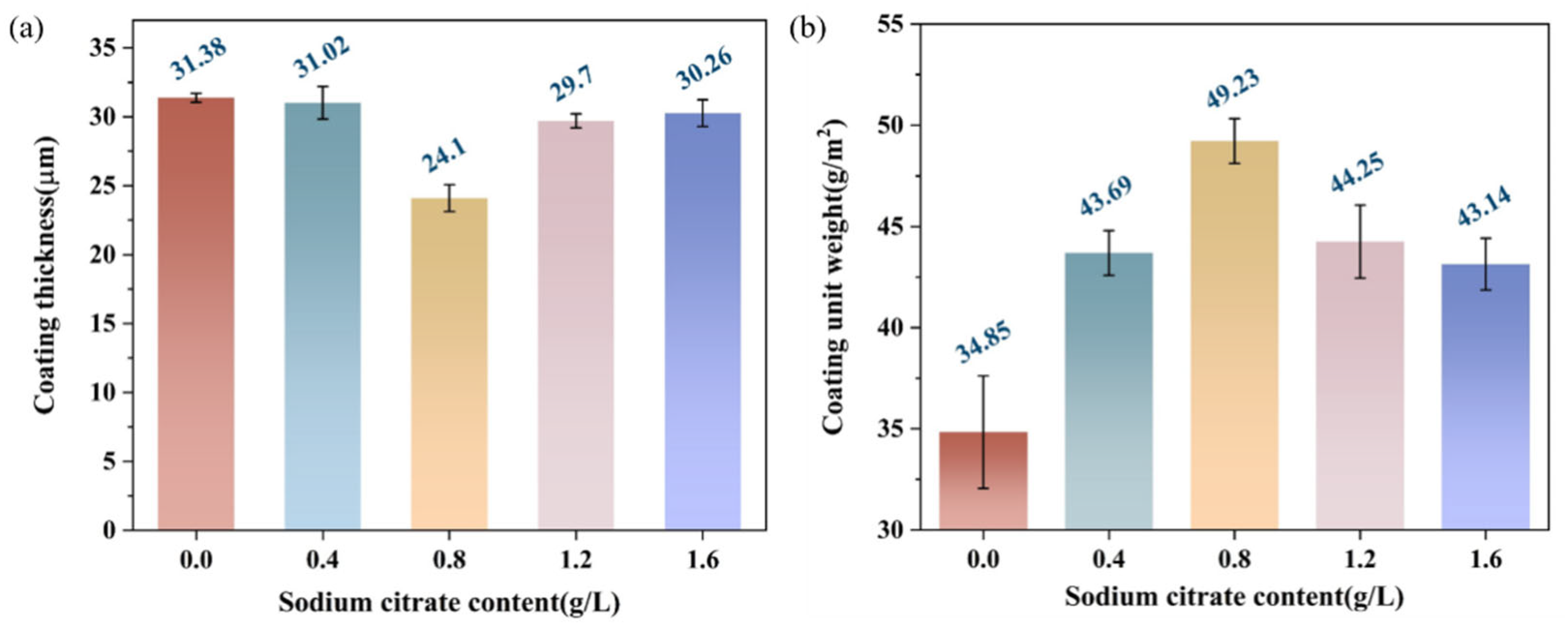
Figure 2a reported that the average thickness of the zinc phosphate coating was about 20–35 μm, and the thickness of the zinc phosphate coating without sodium citrate was 31 μm. With increasing sodium citrate content, the coating thickness reached the minimum value of about 24 μm when the sodium citrate content was 0.8 g/L. The surface-specific mass of the deposit was determined using the dissolution method. According to the standard [20], the samples were immersed in 5% chromic acid solution at 80 °C for 15 min to remove the phosphate coatings. Mass measurements before and after stripping were conducted using a 0.1 mg precision analytical balance. Areal coating density was determined by dividing the mass difference by the specimen surface area. In Figure 2b, the reference coating (without citrate) weighed 34.85 g/m2, while citrate-containing coatings exhibited higher weights of 43.69, 49.23, 44.25, and 43.14 g/m2, respectively. Sodium citrate ( ≤ 0.8 g/L) enhanced crystal growth with porosity reduction, while excess citrate induced defect-dominated crystallization, with maximum coating weight achieved at 0.8 g/L citrate concentration. It showed that the grain size of the coating obtained under these conditions was the finest, and excessive sodium citrate inhibited grain refinement. Combined with the law of coating thickness, it can be considered that the addition of an appropriate amount of sodium citrate played a role in promoting grain growth and refining grains.

3.2. Surface Morphology of the Zinc Phosphate Coatings

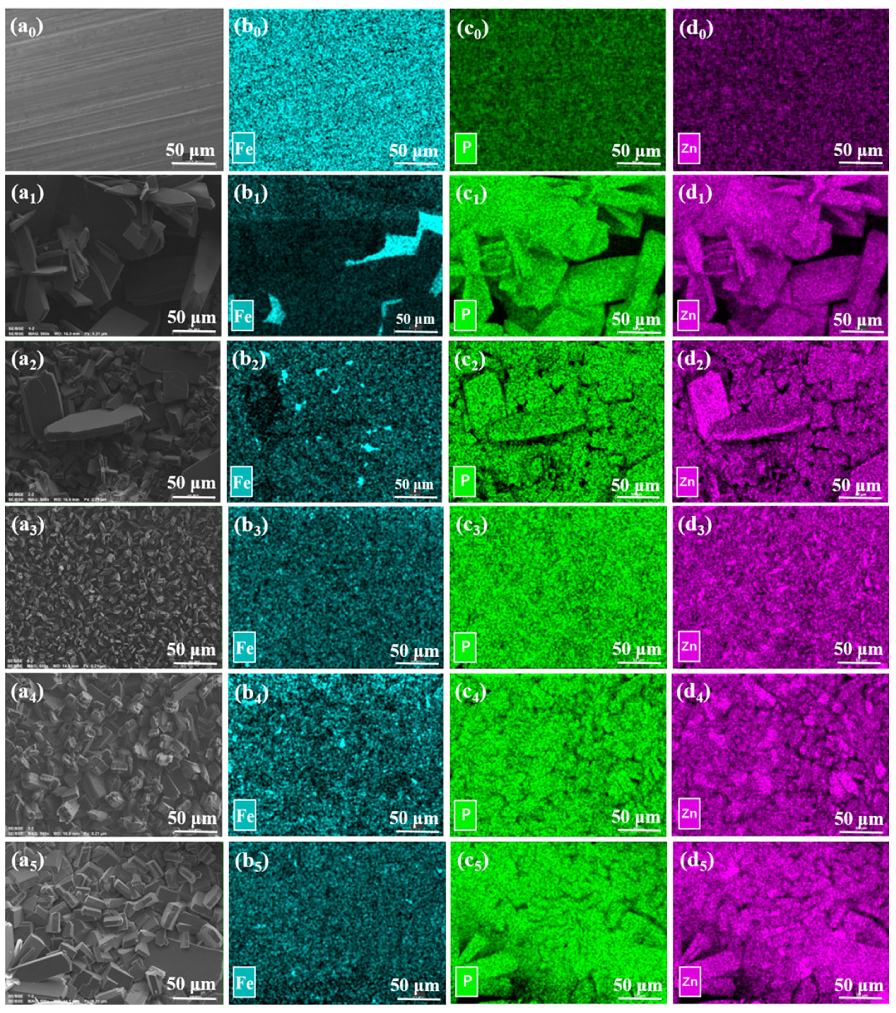
As shown in Figure 3, the surface morphology of various samples was characterized. Similar morphological features of zinc phosphate coatings have been documented in prior studies [20,21,22]. The zinc phosphate crystals are predominantly irregular needles and blocks, and there are many pores between crystals. Figure 3(b1) revealed that phosphate crystals formed in the absence of sodium citrate exhibited coarse and irregular morphology. The mapping of Fe in GCr15 steel showed a uniform highlight, while the mapping of P and Zn also showed a bright area with no obvious brightness (Figure 3(c0,d0)). This resulted from background noise interference. No characteristic peaks for P or Zn were detected above the background noise in the EDS spectra (Figure 3). The Fe elemental mapping in Figure 3(b1) revealed a well-defined bright region, indicating exposure of the underlying iron substrate. However, a significant decrease in brightness was observed relative to GCr15, indicating that the phosphate grains were covered on the surface of GCr15 steel. This showed that the crystal coverage was not so high at this time, and the exposed area will precipitate rapid corrosion deterioration of the steel substrate. After the addition of sodium citrate, the zinc phosphate coating demonstrated reduced grain size and improved morphological uniformity. Sodium citrate promoted substrate dissolution and increased the active surface area of the coating. This, in turn, boosts the nucleation rate of phosphate crystals and promotes film crystallization. EDS mapping showed that there was no highlight in the mapping of Fe in Zn-P3 (Figure 3(b3)); at the same time, the mapping of Zn and P showed the most uniform bright area, indicating that the phosphate grain was the finest and most uniform, and the density was the highest (Figure 3(c3,d3)). With the increase in sodium citrate concentration, the excessive sodium citrate content leads to an increase in the PH value of the phosphate solution, affecting the phosphating reaction, resulting in a reduction in the thickness of Zn-P4 phosphate crystals (Figure 3(a4,a5)), making the coating too thin or forming a loose crystal structure, and causing irregular bright areas to appear in the EDS diagram (Figure 3(b4–d5)).

3.3. Crystal Phase

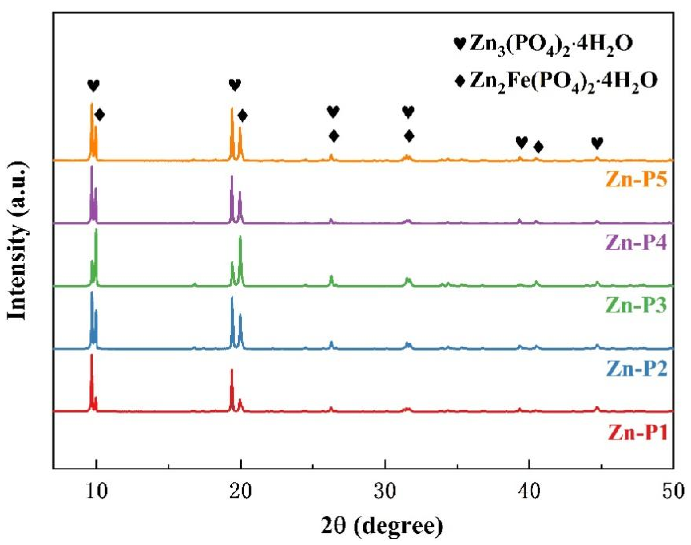
Figure 4 reveals that all phosphate coatings consisted of two crystalline phases: hopeite (Zn3(PO4)2·4H2O, orthorhombic) and phosphophyllite (Zn2Fe(PO4)2·4H2O, monoclinic). Compared with hopeite, phosphophyllite contained Fe2+ and has good adhesion and corrosion resistance [23,24,25]. Variations in hopeite and phosphophyllite peak intensities across coatings reflected differences in their crystalline phase composition [26]. The XRD data of the coatings was mainly concentrated near the phase angles of 10° and 20°. The peaks of the sample without sodium citrate were mainly concentrated in the hopeite, and the peak height of the phosphophyllite was not obvious. It meant that the main crystal component of the Zn-P1 was Zn3(PO4)2·4H2O [24]. The diffraction intensity of the diffraction peak corresponding to Zn2Fe(PO4)2⸱4H2O crystal varies with phosphating time as shown in Figure 4. Incorporation of sodium citrate had no effect on the composition of the zinc phosphating layer. The zinc phosphate coating was still composed of Zn3(PO4)2·4H2O and Zn2Fe(PO4)2·4H2O. However, with the incorporation of sodium citrate, the diffraction peak intensity of the phosphophyllite increased. The peak intensity initially rose and subsequently declined as the sodium citrate concentration increased. Sodium citrate can form a stable soluble complex with Fe2+ in the solution environment, which reduces the probability of Fe2+ oxidation to Fe3+. The peak intensity of Zn2Fe(PO4)2·4H2O on the surface of Zn-P3 reached the highest.
With the addition of sodium citrate, the intensity of Zn3(PO4)2·4H2O and Zn2Fe(PO4)2·4H2O crystals progressively increased. This indicates that after near-complete coverage of the GCr15 substrate by the phosphate coating (Figure 3), iron dissolution ceased to facilitate zinc deposition. Consequently, the absence of fine zinc particles allowed unobstructed growth of Zn3(PO4)2·4H2O and Zn2Fe(PO4)2·4H2O crystals, resulting in large plate-shaped crystal clusters on the surface. This yielded more comprehensive crystal coverage and enhanced substrate protection. The elevated intensities of Zn3(PO4)2·4H2O and Zn2Fe(PO4)2·4H2O crystals correlate with improved surface crystallinity and coating integrity. Critically, the intensified Zn2Fe(PO4)2·4H2O signal—associated with superior adhesion and corrosion resistance—confirms that sodium citrate addition significantly enhances the coating’s anti-corrosion performance.

3.4. Corrosion Property of the Zinc Phosphate Coatings

3.4.1. EIS Analysis

Electrochemical tests were performed using an Autolab electrochemical workstation. The experimental data were processed using ZsimpWin software (V3.60) to extract the charge transfer resistance (Rct) and low-frequency impedance modulus (|Z0.01| Hz, impedance modulus at a frequency of 10−2 Hz) to evaluate the corrosion resistance of GCr15 and different zinc phosphate coatings.
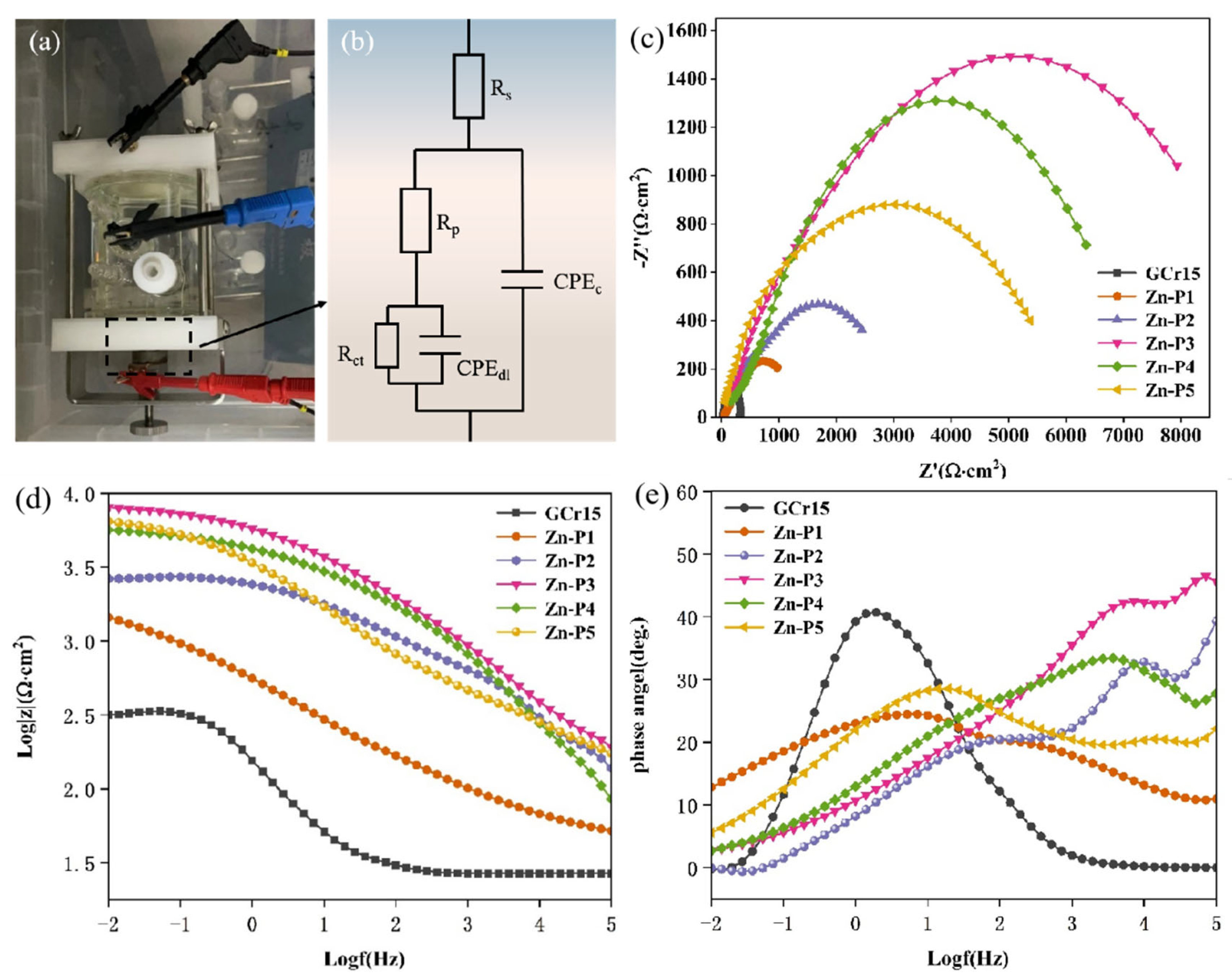
As shown in Figure 5b, the R (Q (R (QR))) model was selected based on the equivalent circuit diagram fitted according to the variation law of the impedance spectrum. Due to the imperfect capacitance characteristics of electric double layers in real electrochemical environments, a constant phase element (CPE) was used instead of an ideal capacitor to represent the coating capacitance. Rs represents the solution resistance, while Rp and Rct denote the coating resistance and charge transfer resistance, respectively. These parameters characterize the charge transfer dynamics at the coating–substrate interface. Specifically, Rp reflects the ionic conduction pathways within the coating, correlating with its porosity and degradation state [27,28]. Upon diffusion of corrosive ions to the interface, the substrate becomes susceptible to corrosion, engaging in charge exchange with the aggressive species. The charge transfer resistance (Rct) quantifies the kinetics of this electrochemical process [29]. The constant phase element (CPE) is employed to model non-ideal capacitive behavior arising from surface heterogeneity. Two CPE components were quantified. CPEc: coating capacitance, characterizing dielectric properties and porosity of the phosphate layer. Lower values indicate denser microstructure. CPEdl: double-layer capacitance, reflecting the charge storage capacity at the coating/substrate interface. Reduced values signify inhibited electrochemical activity at defect sites.
Experimental evidence confirms a direct proportionality between the capacitive arc radius and the corrosion resistance performance of phosphate coatings [30,31,32]. Figure 5c showed that the capacitance arc radius of the sample with phosphate coating on the surface was significantly larger than that of GCr15 steel. Zn-P3 had the largest capacitance arc radius, which indicated that the coated surface exhibits optimal corrosion resistance and maximum barrier protection efficiency. The low-frequency impedance modulus (|Z0.01 Hz|) reflects the barrier properties of coatings, where increased values correspond to enhanced sealing capacity and improved protective performance [33,34,35]. Figure 5d shows that the slopes of the plots of the samples with phosphate coating were negative at high frequencies, which indicated the capacitive characteristics of the phosphate coatings. The curve of GCr15 was approximately a horizontal straight line in the high-frequency region, showing resistance characteristics. The impedance modulus exhibited a positive correlation with sodium citrate concentration in the phosphating solution up to 0.8 g/L, confirming enhanced corrosion resistance imparted by the phosphate coating on GCr15 substrates. Incorporating sodium citrate enhanced the phosphate coating’s barrier performance. The Zn-P3 coating exhibited the highest impedance modulus—approximately 100 times greater than bare GCr15—demonstrating optimal corrosion protection. The Bode phase angle at high frequencies (103–105 Hz, Figure 5e) reflected coating integrity, with 90° proximity denoting optimal coverage [36]. At 105 Hz, GCr15 exhibits a phase angle converging to 10°, while the phase shift in the zinc phosphates increased to varying degrees, with Zn-P3 showing the highest value. With the further increase in sodium citrate content beyond 0.8 g/L, the capacitance arc radius and the protective coating displayed decreasing trends in both impedance and phase parameters, indicating that excessive sodium citrate was not conducive to the improvement of corrosion resistance of the coating.
As shown in Table 3, the Rct obtained from the coating test with added phosphate was significantly higher than that of GCr15, indicating that the surface of GCr15 is prone to corrosion, and charge exchange occurs with corrosion. The formation of the coating on the surface inhibited the diffusion and charge transfer of corrosive ions [35,36]. The addition of sodium citrate resulted in grain refinement, leading to a reduction in coating porosity. The Rct of Zn-P3 (2.957 × 10³ Ω·cm2) was nearly twice the value of the coating without sodium citrate (1.539 × 10³ Ω·cm2), and the Rp (5.02 × 10³ Ω·cm2) was also nearly fifth the value of the coating without sodium citrate (1.013 × 10³ Ω·cm2). At the same time, the CPEc (2.155 × 10⁻⁵ F·cm2·sn−1) and CPEdl (4.988 × 10⁻⁵ F·cm2·sn−1) of the coating under this condition reached their minimum. This showed that Zn-P3 has the densest microstructure exhibiting premium barrier functionality [37,38,39,40,41]. With further increases in sodium citrate content, the Rct and Rp of the coating decreased, while CPEc and CPEdl increased, indicating that excessive citrate (>0.8 g/L) increased porosity relative to Zn-P3.

3.4.2. Surface Corrosion Morphology

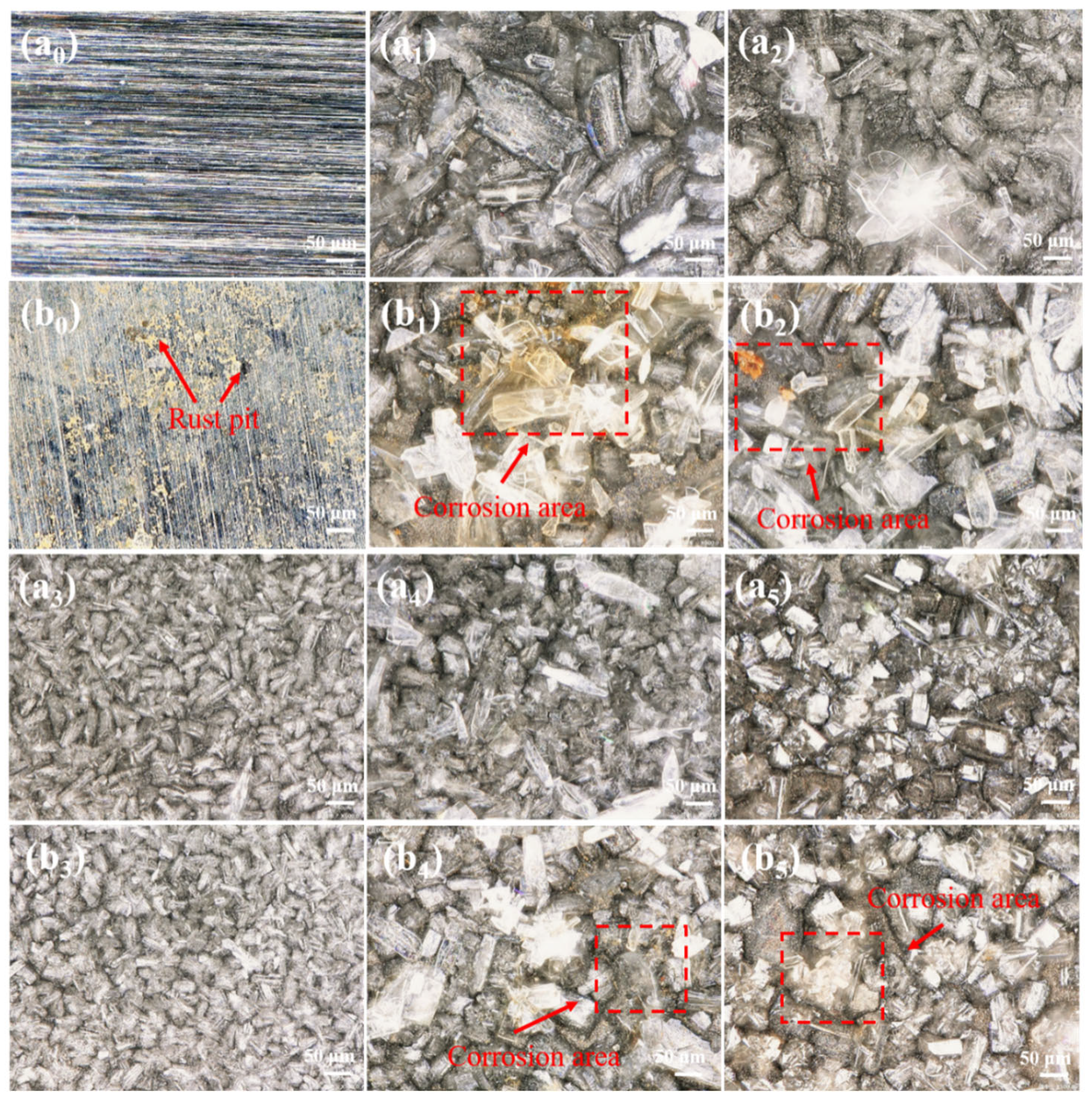
Following 24 h exposure to 3.5% NaCl, the corrosion behavior of bare GCr15 and phosphate-coated variants was evaluated using optical microscopy. Figure 6 illustrates the morphological evolution before and after testing.
After the uncoated sample was immersed in salt water for 24 h, corrosion occurred on its surface, with large rust spots and pits formed by smaller rust particles (Figure 6(b0)). For Zn-P1 and Zn-P2, surface corrosion was significantly reduced compared to GCr15, although no complete protection was achieved, and some corrosion persisted due to insufficient grain coverage. As shown in Figure 6(a3,b3), with increased grain density and uniformity, the crystal coverage of the sample surface was further improved. Zn-P3 showed no surface corrosion after 24 h of immersion, indicating that the phosphate crystals on Zn-P3 effectively protected the matrix and inhibited surface corrosion. It can be seen from Figure 6(a4–b5) that the surface grains of Zn-P4 and Zn-P5 did not exhibit finer or denser morphology and suffered more severe corrosion compared to Zn-P3, suggesting that concentrations exceeding 0.8 g/L sodium citrate did not further improve corrosion resistance.

3.4.3. Potentiodynamic Polarization (PDP) Testing

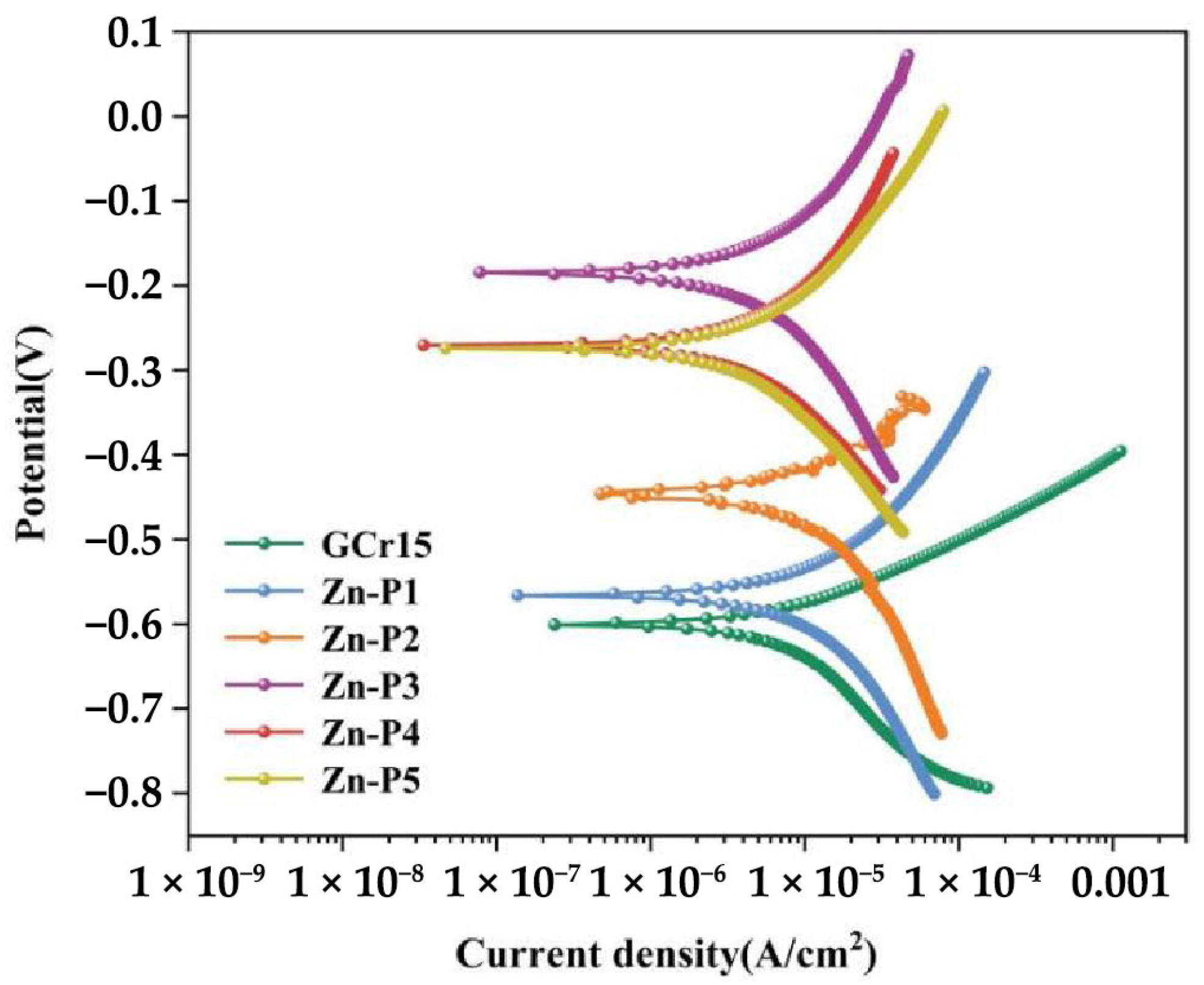
To evaluate the protective performance of the phosphate conversion coatings, potentiodynamic polarization (PDP) tests were conducted (Figure 7). Critical electrochemical parameters—corrosion potential (Ecorr), corrosion current density (Icorr), polarization resistance (Rpo), and Tafel slopes (βa, βb)—were derived through Tafel extrapolation (Table 4). These metrics directly correlate with corrosion kinetics: higher Icorr and lower Rpo values signify accelerated coating dissolution and diminished corrosion resistance [41,42].
As shown in Figure 7, the corrosion potential of the sample with phosphate coating on the surface increased significantly compared to that of GCr15. With the increased content of sodium citrate, a reduction in corrosion current density was observed in the coated specimen. GCr15 demonstrated the maximum corrosion current density (Icorr) of 1.313 × 10⁻⁵ A/cm2, indicating the fastest corrosion rate. After phosphating treatment, the Icorr of the sample decreased by about an order of magnitude compared to GCr15, demonstrating the protective effect of the phosphate coating. The Zn-P3 coating showed the lowest corrosion current density of 1.1635 × 10⁻⁷ A/cm2 and the highest polarization resistance of 1.495 × 10¹⁰ Ω·cm2, effectively blocking the penetration of corrosive electrolytes.

3.5. Friction and Wear

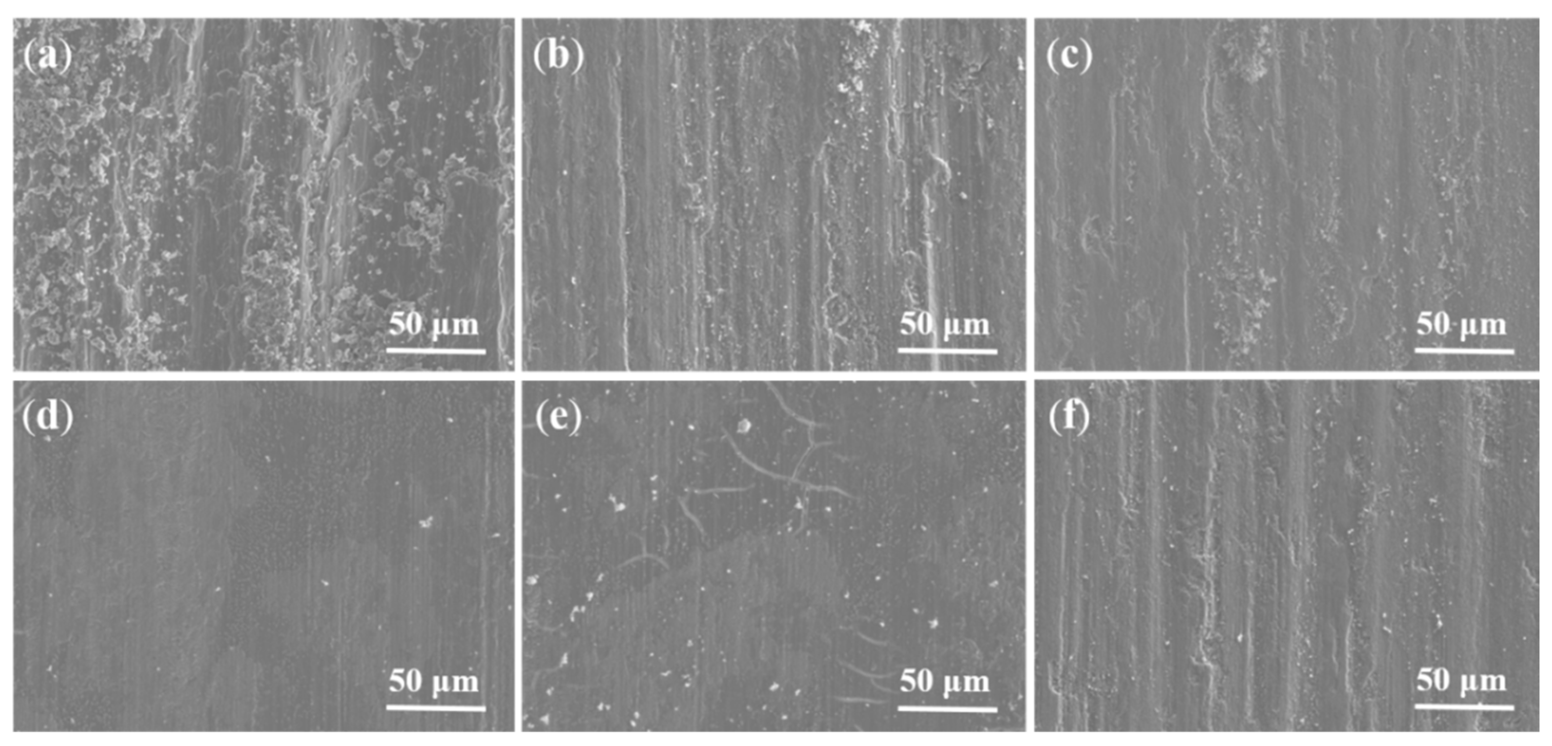
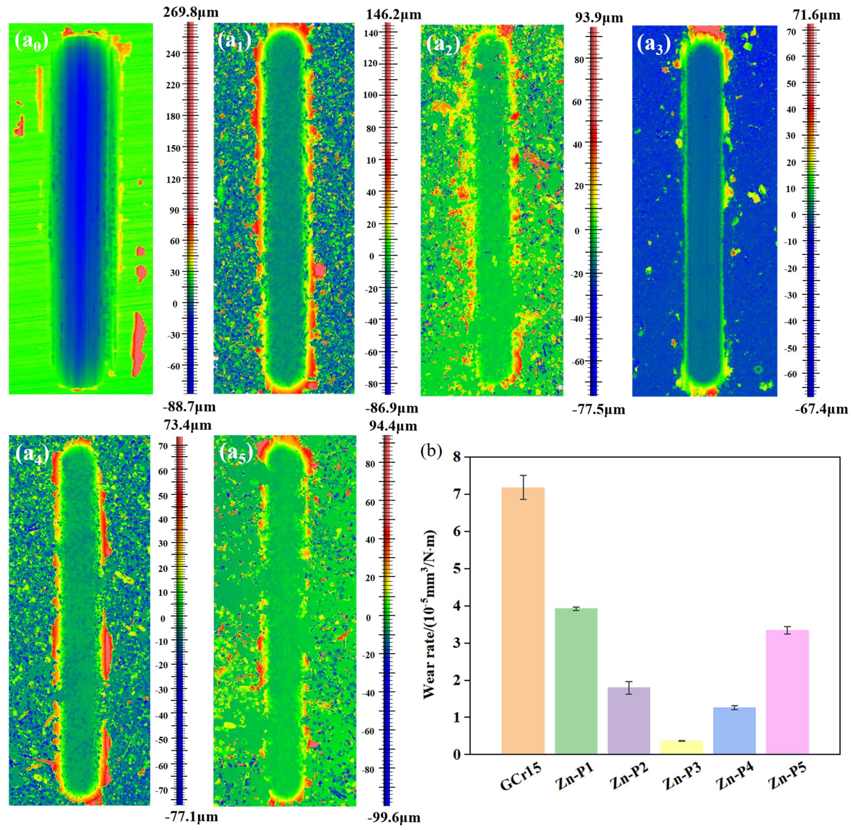
Figure 8 shows that under the same working conditions, the coefficient of friction of Zn-P3 is the smallest, which indicates that Zn-P3 has a better ability to reduce friction under specific working conditions. Figure 9a showed that the wear surface of GCr15 was obviously rough, with significant wear debris accumulation and deep furrows. At the same time, there were some obvious pits and large spalling, showing more serious adhesive wear [43]. The SEM images of the corresponding upper pattern balls can also be seen. Significant wear debris and pronounced friction peaks accumulated in the wear area. The wear rate of the lower pattern was also the largest. Following the formation of zinc phosphate coatings, the specimens exhibited diminished adhesive wear. However, Zn-P1 exhibited large and uneven grain sizes, leading to deep furrows and slight spalling on the wear surface. Despite this, wear debris accumulation was reduced (Figure 9b), and wear volume decreased (Figure 10). The addition of sodium citrate resulted in smaller, more uniform zinc phosphate grains and improved coating compactness, thereby reducing friction and wear. The wear surface of the Zn-P3 sample was the smoothest, showing the greatest improvement. The depth of the wear spot area was significantly reduced, with no spalling or obvious furrows observed (Figure 9d). The smooth wear track (Figure 9d) and reduced friction of Zn-P3 are attributed to in situ formation of a zinc phosphate-based transfer film on the 100Cr6 counterface. This film originates from mechanical transfer: soft zinc phosphate crystals (Vickers hardness ~150 HV) detach from the coating under shear stress. Tribochemical reaction: frictional heating (>150 °C at asperities) promotes adhesion of dehydrated Zn3(PO4)2 to the steel ball. As shown in Figure 11d, EDS confirmed Zn/P-rich patches on the ball surface. This third-body layer reduces metal-to-metal contact, explaining the low COF (0.578) and wear volume (94.8% reduction vs. GCr15). EDS results also showed the highest P and Zn content (Figure 11d), with the wear rate reduced to its minimum, 94.8% lower than that of the matrix (Figure 10b). Further increasing the sodium citrate content did not lead to additional improvements in the uniformity and compactness of the zinc phosphate grains. At the same time, observations of the Zn-P4 coating wear area revealed fine cracks and increased wear debris (Figure 9e). The wear spot area of the upper pattern was more obvious than that of Zn-P3 (Figure 11e). The wear area of Zn-P5 appeared with deeper furrows, and the wear volume was also increased compared to Zn-P3. In summary, the Zn-P3 sample exhibited the best tribological properties.

3.6. Analysis of Phosphate Crystal Formation

The phosphating reaction is a complex chemical and electrochemical reaction. Although there have been numerous studies on phosphating, its specific reaction mechanism has not been fully explained. Currently, it is widely recognized that the phosphating reaction mainly consists of the following four reaction steps:
(1) When metals are eroded by acid and dissolve to produce hydrogen gas, this step is merely the corrosion of the metal and does not result in the formation of a film. The reaction is as follows:
F e 2 e F e 2 +     2 H + + 2 e 2 [ H ] H 2    
(2) The accelerator consumes the hydrogen atoms produced in the first step by reacting with hydrogen, significantly reducing the H+ concentration at the metal interface and converting Fe2+ to Fe3+, thereby accelerating the formation rate of the phosphating film. The reaction is as follows:
Oxidizing   agent + H R e d u c t i o n   p r o d u c t + [ H 2 O ] 2 F e 2 + + Oxidizing   agent F e 3 + + R e d u c t i o n   p r o d u c t  
(3) The hydrolysis of acid phosphates releases free phosphoric acid, reducing the H+ concentration on the metal surface and promoting the positive progress of the stepwise dissociation equilibrium of phosphate ions, ultimately forming stable phosphate ions:
H 3 P O 4 H 2 P O 4   +   H + H P O 4 2   +   2 H + P O 4 3   +   3 H +      
(4) P O 4 3 generated on the metal surface react with metal ions in the phosphating solution (such as Zn2+, Ca2+, Mn2+, etc.). The phosphate crystallizes with four water molecules to form grains. After the grains stabilize, they deposit on the metal surface, forming a phosphating film that is insoluble in water.
2 Z n 2 + + F e 2 + + 2 P O 4 3 + 4 H 2 O Z n 2 F e P O 4 2 4 H 2 O P h o s p h a t i n g   f i l m 3 Z n 2 + + 2 P O 4 3 + 4 H 2 O Z n 3 P O 4 2 4 H 2 O P h o s p h a t i n g   f i l m        
The mechanism of the phosphating reaction can serve as a reference for optimizing the phosphating process and formula. Theoretically, both the phosphating temperature and the accelerator can accelerate the speed of reaction (3) to varying degrees, speed up the formation of the phosphating film, and at the same time lead to a decrease in H+ concentration, thereby promoting the hydrolysis equilibrium to shift to the right and increasing the concentration, which in turn promotes the progress of reaction (5) and the formation of phosphate crystals.

4. Conclusions

In this study, citric acid was selected over sodium nitrite to enhance the phosphating reaction and ensure the environmental safety of the phosphating process. At the same time, sodium citrate was added to further improve the quality of the phosphate coating. The addition of specific concentrations of citric acid and sodium citrate can enhance the nucleation rate of phosphate crystals. The synergistic effect of citric acid and sodium citrate adjusted the free acidity in the phosphate solution and increased the nucleation rate of phosphate crystals. The dense, low-porosity coating provides superior barrier protection against corrosion while simultaneously enhancing wear resistance. Compared to GCr15, the phosphate coatings demonstrated improved corrosion protection and enhanced wear performance, with Zn-P3 demonstrating the best overall performance. The coating CPEc (2.155 × 10⁻⁵ F·cm2·sn−1) and CPEdl (4.988 × 10⁻⁵ F·cm2·sn−1) under this condition were nearly two orders of magnitude lower than those of GCr15, indicating the strongest corrosion resistance. Tribological tests showed that Zn-P3 had the lowest average friction coefficient, with wear loss 94.8% lower than that of GCr15. In terms of environmental protection, compared with the traditional phosphating process, using sodium citrate instead of nitrite as a promoter eliminates the risk of cancer, and the citrate waste liquid can also be biodegraded to significantly reduce the heavy metal load. Therefore, this study demonstrated that the synergistic effect of citric acid and sodium citrate can improve the performance of phosphate coatings. And we proposed a complete set of environmentally friendly phosphating processes and verified their feasibility and practical application value in the marine environment. This study holds substantial importance for implementing phosphate-based corrosion protection in marine environments, simultaneously achieving economic viability and ecological advantages.

Author Contributions

Conceptualization, L.L.; Methodology, T.Y. and L.L.; Software, L.L.; Validation, D.B.; Formal analysis, T.Y. and G.X.; Investigation, Y.X.; Writing—original draft, B.W.; Writing—review & editing, T.Y. and L.Z.; Visualization, G.C.; Supervision, C.P. All authors have read and agreed to the published version of the manuscript.

Funding

This work was supported by the Beijing Natural Science Foundation of China (Grant No. 3242006).

Data Availability Statement

The original contributions presented in the study are included in the article, further inquiries can be directed to the corresponding author.

Conflicts of Interest

Authors Chenyang Pan and Guoxing Chen were employed by the company Suzhou Nuclear Power Research Institute Co., Ltd. The remaining authors declare that the research was conducted in the absence of any commercial or financial relationships that could be construed as a potential conflict of interest.

References

  1. Cai, H.; Li, X.; Zhang, Y.; Yang, C.; Cui, S.; Sheng, L.; Wu, Z. A high corrosion-resistant waterborne epoxy resin coating improved by addition of multi-interface structured zinc phosphate particles. J. Mater. Res. Technol. 2023, 26, 7829–7844. [Google Scholar] [CrossRef]
  2. Tong, H.T.; Liu, X.H.; Liu, Y.P.; Zhang, H.X.; Li, X.B. Electrochemical investigation of the corrosion inhibiting effect of organic paints doped with benzotriazole coated on steel substrates. Corros. Eng. Sci. Technol. 2021, 56, 618e25. [Google Scholar]
  3. Wang, J.; Wu, M.; Huang, J.; Miao, X.; Chen, Y.; Zhao, Y. In Situ Polymerized Self-Healing Microcapsules as Multifunctional Fillers toward Phosphate Ceramic Coatings. ACS Appl. Mater. Interfaces 2024, 16, 26768–26786. [Google Scholar] [CrossRef]
  4. Aswathy, S.P.; Kumar, A.S.; Saji, V.S.; Shibli, S.M. A Near-Infrared Reflectance, Thermal Shielding, and Corrosion Resistance of Neodymium-Modified Zinc Aluminate Spinel-Based Zinc Phosphate Coatings. Adv. Eng. Mater. 2024, 27, 2401351. [Google Scholar] [CrossRef]
  5. Zhang, P.J.; Liu, Q.; Huang, J.; Cui, J.W.; Sun, W.; Li, B.S.; Xu, G.Q. Phosphate conversion of electroplated Ni coatings on NdFeB magnets improving the anticorrosion Property. J. Alloys Compd. 2022, 922, 166206. [Google Scholar] [CrossRef]
  6. Zang, L.B.; Zhong, Q.L.; Chen, Y.; Hou, W.J.; Zhao, B.S.; Wu, Y.M. Effect of coating thickness on tribological properties of manganese phosphate conversion coating in different motion conditions. Tribol. Int. 2022, 176, 107894. [Google Scholar] [CrossRef]
  7. Chai, H.; Wang, L.F.; Cao, X.Q.; Zhang, Q.; Arthanari, S.; Lee, H.; Huang, G.S.; Xing, B.; Zheng, L.W.; Zhang, H.; et al. The effects of chemical conversion parameters on morphology and corrosion performance of calcium phosphate coating on AZ31 alloy, Mater. Chem. Phys. 2023, 296, 127338. [Google Scholar]
  8. Soroush, E.; Davarpanah, A.; Keramatinia, M.; Nouri, N.; Ramezanzadeh, B. Synergistic impact of the functionalized graphene oxide (fGO) nano-sheets and Mn2+-doped zinc phosphate conversion film on the polyester coating corrosion protection properties. Colloids Surf. A Physicochem. Eng. Asp. 2023, 678, 132510. [Google Scholar] [CrossRef]
  9. Han, X.C.; Li, N.; Wu, B.; Li, D.Y.; Pan, Q.M.; Wang, R. Microstructural characterization and corrosion resistance evaluation of chromate-phosphate/water-soluble resin composite conversion coating on Al surfaces. Prog. Org. Coat 2022, 173, 107205. [Google Scholar] [CrossRef]
  10. Liu, H.L.; Tong, Z.P.; Yang, Y.; Zhou, W.F.; Chen, J.N.; Pan, X.Y.; Ren, X.D. Preparation of phosphate conversion coating on laser surface textured surface to improve corrosion performance of magnesium alloy. J. Alloys Compd. 2021, 865, 158701. [Google Scholar] [CrossRef]
  11. Narayanan, T.S.N.S. Surface pretretament by phosphate conversion Coatings a review. Rev. Adv. Mater. Sci. 2005, 9, 130–177. [Google Scholar]
  12. Li, G.Y.; Lian, J.; Niu, L.; Jiang, H. Influence of pH of Phosphating Bath on the Zinc Phosphate Coating on AZ91D Magnesium Alloy. Adv. Eng. Mater. 2006, 8, 123–127. [Google Scholar] [CrossRef]
  13. Ramezanzadeh, B.; Akbarian, M.; Ramezanzadeh, M.; Mahdavian, M.; Alibakhshi, E.; Kardar, P. Corrosion protection of steel with zinc phosphate conversion coating and post-treatment by hybrid organic-inorganic sol gel based silane film. J. Electrochem. Soc. 2017, 164, 224. [Google Scholar] [CrossRef]
  14. Su, H.Y.; Lin, C.S. Effect of additives on the properties of phosphate conversion coating on electrogalvanized steel sheet. Corros. Sci. 2014, 83, 137–146. [Google Scholar] [CrossRef]
  15. Lin, B.L.; Lu, J.T.; Kong, G. Effect of Molybdate Post Sealing on the Corrosion Resistance of Zinc Phosphate Coatings on Hot-Dip Galvanized Steel. Corros. Sci. 2008, 50, 962–967. [Google Scholar] [CrossRef]
  16. Deepa, L.C. Effect of divalent cations in low zinc ambient temperature phosphating bath. Anticorros. Methods Mater. 2003, 502, 86–90. [Google Scholar] [CrossRef]
  17. Zhang, Y.Y.; Chen, X.H.; Tan, H.Y. Effect of ultrasonic treatment on the morphology and corrosion resistance of zinc-manganese phosphate coatings on 16Mn steel in 3.5% sodium chloride. Int. J. Electrochem. Sci. 2023, 18, 100274. [Google Scholar] [CrossRef]
  18. Pokorny, P.; Szelag, P.; Novak, M.; Mastny, L.; Brozek, V. Thermal stability of phosphate coatings on steel. Metalurgija 2015, 54, 489–492. [Google Scholar]
  19. Qi, Z.H.; Zhao, Y.H.; Ji, M.B.; Wang, G.X.; Ying, L.X.; Wang, Z.D.; Krit, B. Preparation of chitosan/phosphate composite coating on Mg alloy (AZ31B) via one step chemical conversion method. Resour. Chem. Mater. 2023, 2, 39–48. [Google Scholar] [CrossRef]
  20. Jiang, C.C.; Zhang, X.Z.; Wang, D.; Zhang, L.; Cheng, X. Phosphate conversion coatings on 35CrMnSi steels subjected to different heat treatments. Electrochem. Commun. 2020, 110, 106636. [Google Scholar] [CrossRef]
  21. Tamilselvi, M.; Kamaraj, P.; Arthanareeswari, M.; Devikala, S. Nano zinc phosphate coatings for enhanced corrosion resistance of mild steel. Appl. Surf. Sci. 2015, 327, 218–225. [Google Scholar] [CrossRef]
  22. Tamilselvi, M.; Kamaraj, P.; Arthanareeswari, M.; Devikala, S.; Arockiaselvi, J.; Pushpamalini, T. Effect of nano ZrO2 on nano zinc phosphating of mild steel. Mater. Today Proc. 2018, 5, 8880–8888. [Google Scholar] [CrossRef]
  23. He, X.L.; Wu, J.X.; Chen, Y.; Zhang, L.; Sheng, X.X. A trace amount of MXene@PDA nanosheets for low-temperature zinc phosphating coatings with superb corrosion resistance. Appl. Surf. Sci. 2022, 603, 154455. [Google Scholar] [CrossRef]
  24. Zhao, Y.; Ren, H.; Dai, H.; Jin, W. Composition and expansion coefficient of rust based on X-ray diffraction and thermal analysis. Corros. Sci. 2011, 53, 1646–1658. [Google Scholar] [CrossRef]
  25. Tamilselvi, M.; Kamaraj, P.; Arthanareeswari, M.; Devikala, S.; Selvi, J.A. Development of nano SiO2 incorporated nano zinc phosphate coatings on mild steel. Appl. Surf. Sci. 2015, 332, 12–21. [Google Scholar] [CrossRef]
  26. Yu, X.; Wang, J.; Zhang, M.; Yang, L.; Li, J.; Yang, P.; Cao, D. characterization and anticorrosion performance of molybdate pillared hydrotalcite in situ created ZnO composite as pigment for Mg–Li alloy protection. Surf. Coat. Technol. 2008, 203, 250–255. [Google Scholar] [CrossRef]
  27. Gimeno, M.J.; Puig, M.; Chamorro, S.; Molina, J.; March, R.; Oro, E.; P’erez, P.; Gracenea, J.J.; Suay, J.J. Improvement of the anticorrosive properties of an alkyd coating with zinc phosphate pigments assessed by NSS and ACET. Prog. Org. Coat. 2016, 95, 46–53. [Google Scholar] [CrossRef]
  28. Huang, H.; Li, M.; Tian, Y.; Xie, Y.; Sheng, X.; Jiang, X.; Zhang, X. Exfoliation and functionalization of α-zirconium phosphate in one pot for waterborne epoxy coatings with enhanced anticorrosion performance. Prog. Org. Coat. 2020, 138, 105390. [Google Scholar] [CrossRef]
  29. Thompson, I.; Campbell, D. Interpreting Nyquist responses from defective coatings on steel substrates. Corros. Sci. 1994, 36, 187–198. [Google Scholar] [CrossRef]
  30. Haddadi, S.A.; Keramatinia, M.; Ramezanzadeh, M.; Ramezanzadeh, B. Detailed experimental investigation of the highly active corrosion inhibitive green molecules based on zinc cations/Nepeta Pogonosperma extract and toward the corrosion mitigation of mild steel in the saline solution. Colloids Surf. A Physicochem. Eng. Asp. 2022, 642, 128613. [Google Scholar] [CrossRef]
  31. Zhou, X.; Huang, H.; Zhu, R.; Sheng, X.; Xie, D.; Mei, Y. Facile modification of graphene oxide with Lysine for improving anti-corrosion performances of waterborne epoxy coatings. Prog. Org. Coat. 2019, 136, 105200. [Google Scholar] [CrossRef]
  32. Xu, W.; Wang, Z.; Han, E.H.; Wang, S.; Liu, Q. Corrosion performance of nano-ZrO2 modified coatings in hot mixed acid solutions. Materials 2018, 11, 934. [Google Scholar] [CrossRef]
  33. Keramatinia, M.; Majidi, R.; Ramezanzadeh, B. La-MOF coordination polymer: An effective environmentally friendly pH-sensitive corrosion inhibitive-barrier nanofiller for the epoxy polyamide coating reinforcement. J. Environ. Chem. Eng. 2022, 10, 108246. [Google Scholar] [CrossRef]
  34. Ramezanzadeh, B.; Ghasemi, E.; Mahdavian, M.; Changizi, E.; MohamadzadehMoghadam, M.H. Covalently-grafted graphene oxide nanosheets to improve barrier and corrosion protection properties of polyurethane coatings. Carbon 2015, 93, 555–573. [Google Scholar] [CrossRef]
  35. Duraipandian, M. Effects of Fe2O3 and B4C Addition on the Mechanical Properties and Corrosion Resistance of Al–Mg–Si Alloy in 3.5% Brine Solution. Met. Mater. Int. 2021, 27, 1506–1518. [Google Scholar] [CrossRef]
  36. Al-Mamun, N.S.; Haider, W.; Shabib, I. Corrosion resistance of additively manufactured 316L stainless steel in chloride-thiosulfate environment. Electrochim. Acta 2020, 362, 137039. [Google Scholar] [CrossRef]
  37. Zeng, D.; Liu, Z.; Bai, S. Corrosion resistance of bis-si-lane-modified epoxy coatings on an Al-Zn-Mg-Cu alloy. J. Mater. Eng. Perform. 2020, 288, 5282–5290. [Google Scholar] [CrossRef]
  38. Ma, Y.; Zhang, Q.J.; An, L.Y. Effects of volt-age on electrochemical corrosion behavior of micro-arc oxida-tion coatings. J. Lanzhou Univ. Technol. 2020, 46, 1. [Google Scholar]
  39. Rui, S.J.; Shao, S.; Li, Z.X. Study on prepa-ration and anticorrosion of silane sealing film on carbon steel. New Chem. Mater. 2019, 47, 267–271. [Google Scholar]
  40. Tian, Y.; Qiu, W.; Xie, Y.; Huang, H.; Hu, J.; Zhong, L.; Jiang, X.; Zhang, X. Melatonin as an Accelerating Agent for Phosphate Chemical Conversion Coatings on Mild Steel with Enhanced Corrosion Resistance. J. Electrochem. Soc. 2020, 167, 101505. [Google Scholar] [CrossRef]
  41. Parhizkar, N.; Ramezanzadeh, B.; Shahrabi, T. Corrosion protection and adhesion properties of the epoxy coating applied on the steel substrate pre-treated by a solgel based silane coating filled with amino and isocyanate silane functionalized graphene oxide nanosheets. Appl. Surf. Sci. 2018, 439, 45–59. [Google Scholar] [CrossRef]
  42. Mo, S.; Ye, J.; Jia, L.; Chen, Y. Properties and performance of hybrid suspensions of MPCM/nanoparticles for LED thermal management. Energy 2022, 239, 122650. [Google Scholar] [CrossRef]
  43. Jaber, N.B.; Drevet, R.; Fauré, J.; Demangel, C.; Potiron, S.; Tara, A.; Benhayoune, H. A New Process for the Thermal Treatment of Calcium Phosphate Coatings Electrodeposited on Ti6Al4V Substrate. Adv. Eng. Mater. 2015, 17, 1608–1615. [Google Scholar] [CrossRef]
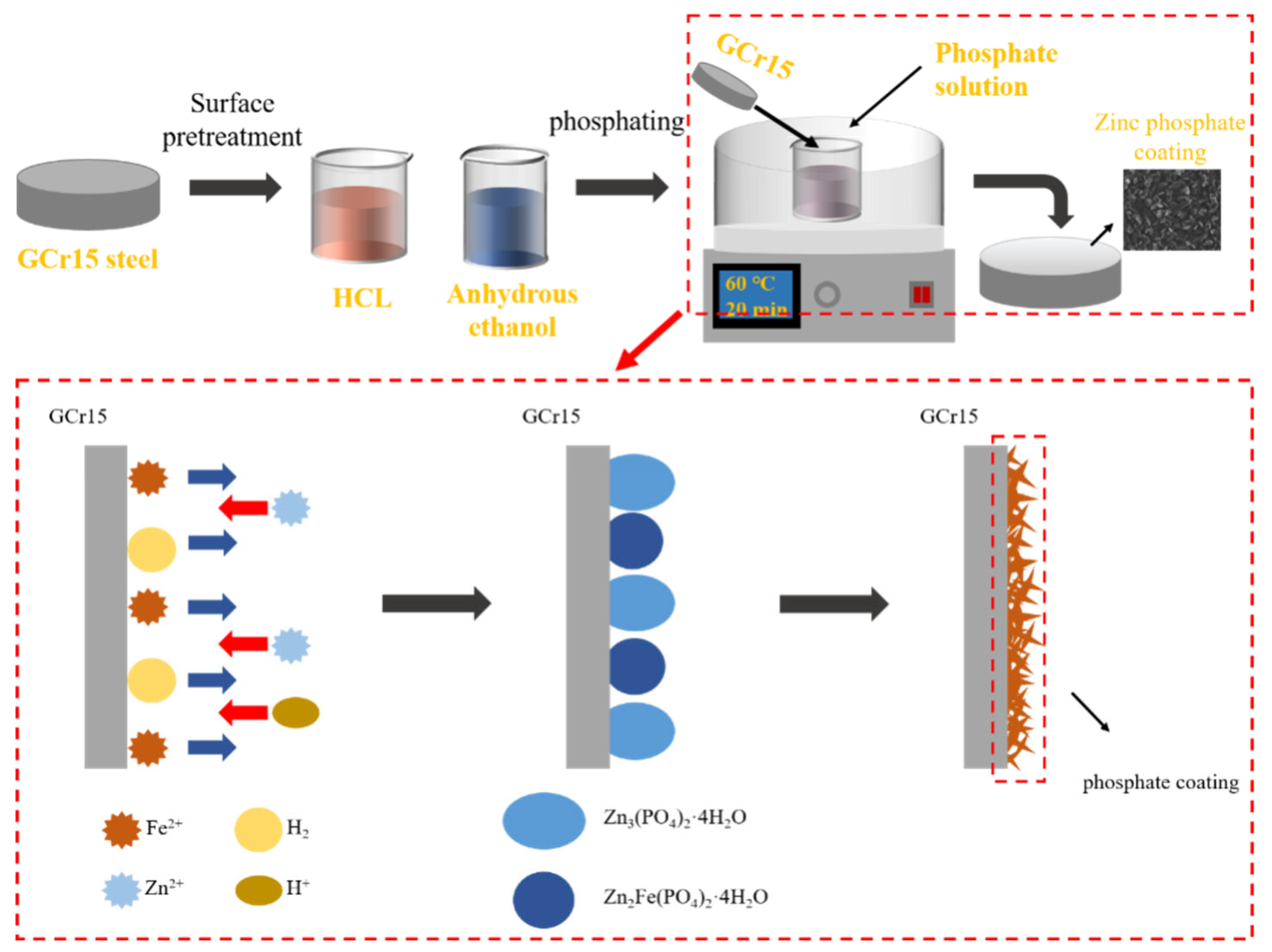
Figure 1. Flow chart of phosphating treatment.
Lubricants 13 00367 g001
Figure 2. Thickness of the zinc phosphate coating (a); unit weight of the zinc phosphate coating (b).
Lubricants 13 00367 g002
Figure 3. The SEM image and EDS mapping of GCr15 (a0d0); Zn-P1 (a1d1); Zn-P2 (a2d2); Zn-P3 (a3d3); Zn-P4 (a4d4); Zn-P5 (a5d5).
Lubricants 13 00367 g003
Figure 4. XRD curves.
Lubricants 13 00367 g004
Figure 5. Electrochemical test instrument (a); the equivalent electrical circuits (b); Nyquist (c), Bode modulus (d), and Bode phase angle (e) plots of GCr15 and the phosphate coatings.
Lubricants 13 00367 g005
Figure 6. Morphology before and after soaking in salt water of GCr15 (a0,b0); Zn-P1 (a1,b1); Zn-P2 (a2,b2); Zn-P3 (a3,b3); Zn-P4 (a4,b4); Zn-P5 (a5,b5).
Lubricants 13 00367 g006
Figure 7. PDP curves of GCr15 and phosphate coatings immersed in 3.5 wt% NaCl solution.
Lubricants 13 00367 g007
Figure 8. COF versus sliding time for the samples (a); average friction coefficient of the samples (b).
Lubricants 13 00367 g008
Figure 9. SEM morphology of wear surface: GCr15 (a); Zn-P1 (b); Zn-P2 (c); Zn-P3 (d); Zn-P4 (e); Zn-P5 (f).
Lubricants 13 00367 g009
Figure 10. Surface morphologies of the wear surfaces: GCr15 (a0); Zn-P1 (a1); Zn-P2 (a2); Zn-P3 (a3); Zn-P4 (a4); Zn-P5 (a5); wear rate histogram of samples (b).
Lubricants 13 00367 g010
Figure 11. Abrasion surface analysis of steel balls: GCr15 (a); Zn-P1 (b); Zn-P2 (c); Zn-P3 (d); Zn-P4 (e); Zn-P5 (f).
Lubricants 13 00367 g011
Table 1. Chemical composition of GCr15 steel.
ElementCSiMnCrMoSNi
Mass fraction/%0.95–1.050.15–0.350.25–0.451.40–1.65≤0.10≤0.025≤0.030
Table 2. The formulation of the phosphate solution.
Phosphate SolutionComposition and Content
ZnO/g·L−1H3PO4/mL·L−1NaF/g·L−1C6H8O7/g·L−1C6H5Na3O7/g·L−1
P1620420
P2620420.4
P3620420.8
P4620421.2
P5620421.6
Table 3. Electrochemical parameters obtained by electrochemical impedance spectroscopy.
SampleRp
(Ω·cm2)
Rct
(Ω·cm2)
|Z0.01 Hz|
(Ω·cm2)
CPEc
(F·cm2·sn−1)
CPEdl
(F·cm2·sn−1)
GCr1515.925730.574.361 × 10−34.883 × 10⁻³
Zn-P11.013 × 1031.539 × 103168.068.276 × 10−43.55 × 10⁻⁵
Zn-P21.34 × 1031.551 × 1031070.241.796 × 10−53.658 × 10⁻⁵
Zn-P35.02 × 1032.957 × 1031987.372.155 × 10−54.988 × 10⁻⁵
Zn-P42.976 × 1031.678 × 1031732.361.547 × 10−53.652 × 10⁻⁵
Zn-P52.927 × 1031.307 × 103818.901.054 × 10−52.991 × 10⁻⁵
Table 4. Tafel extrapolation results obtained from PDP curves.
SampleEcorr
(mV)
Icorr
(A/cm2)
Rpo
(Ω⸱cm2)
βa
(mV/dec)
βb
(mV/dec)
GCr15−0.5417951.313 × 10−51.645 × 107441.41−3909.87
Zn-P1−0.540765.81 × 10−62.525 × 109876.74−3939.58
Zn-P2−0.44961811.619 × 10−63.0243 × 1091823.03−3958.54
Zn-P3−0.198031.1635 × 10−71.495 × 10105204.36−7656.94
Zn-P4−0.262481.159 × 10−61.064 × 10105940.98−7511.82
Zn-P5−0.2653751.762 × 10−64.004 × 1097951.98−6635.11
Disclaimer/Publisher’s Note: The statements, opinions and data contained in all publications are solely those of the individual author(s) and contributor(s) and not of MDPI and/or the editor(s). MDPI and/or the editor(s) disclaim responsibility for any injury to people or property resulting from any ideas, methods, instructions or products referred to in the content.