Article

Microstructure, Mechanical and Tribological Properties of Cu40Zn-Ti3AlC2 Composites by Powder Metallurgy

1
School of Materials Science and Engineering, Taizhou University, Taizhou 318000, China
2
International Joint Institute of Advanced Coating Technology, Taizhou University, Taizhou 318000, China
3
Wenling Research Institute, Taizhou University, Taizhou 318000, China
4
Zhejiang Provincial Key Laboratory for Cutting Tools, Taizhou University, Taizhou 318000, China
5
Tiangong Aihe Co., Ltd., Danyang 212300, China
6
Ningbo Boway Alloy Material Co., Ltd., Ningbo 315042, China
7
Metal-Polymer Research Institute, National Academy of Sciences of Belarus, 246050 Gomel, Belarus
*
Authors to whom correspondence should be addressed.
Lubricants 2024, 12(9), 306; https://doi.org/10.3390/lubricants12090306
Submission received: 8 August 2024 / Revised: 28 August 2024 / Accepted: 29 August 2024 / Published: 31 August 2024

Abstract

:
The exploration of unleaded free-cutting Cu40Zn brass with excellent mechanical and tribological properties has always drawn the attention of researchers. Due to its attractive properties combining metals and ceramics, Ti3AlC2 was added to Cu40Zn brass using high-energy milling and hot-pressing sintering. The effects of Ti3AlC2 on the microstructure, mechanical and tribological properties of Cu40Zn-Ti3AlC2 composites were studied. The results showed that Ti3AlC2 could suppress the formation of ZnO by adsorbing oxygen impurity and promote the formation of the β phase by releasing the β-forming element Al to the substrate. The hardness and wear resistance of Cu40Zn-Ti3AlC2 composites increased with increasing Ti3AlC2 content from 0 to 5 wt.%. The proper Ti3AlC2 additive was beneficial to both the strength and plasticity of the composites. The underlying mechanisms were discussed.

1. Introduction

Owing to its outstanding mechanical properties, good corrosion resistance, superior thermal and electrical conductivity and excellent formability, Cu40Zn (Cu-40wt.% Zn) brass, mainly comprising the Cu-based FCC solid-solution phase (α phase) and the CuZn-based BCC solid-solution phase (β phase), shows extensive applications in the fields of navigation, automobiles, electronics and domestic water [1,2,3].
To improve the machinability of Cu40Zn, 1~4 wt.% Pb is always added to the alloy. In leaded Cu40Zn brass, soft and low-melting Pb globules, stemming from eutectic reaction during solidification, can act as a breakpoint of the cutting scraps and lubricating agent for the cutting process [4,5]. These two effects enable the excellent machinability of leaded Cu40Zn brass. However, it is well known that Pb inflicts serious harm to the environment and human beings. As a result, the exploration of unleaded free-cutting Cu40Zn brass has always drawn the attention of researchers [6]. Until now, there have been two strategies to explore unleaded free-cutting Cu40Zn brass. The first is alloying, that is, adopting Bi, Sb, Mg, Si and other elements as alternatives to Pb. Bi shows a similar mechanism to Pb for improving the machinability of Cu40Zn brass [7]. However, it is easy with Bi to form a film along the phase boundary. Hot shortness originating from the melting of Bi film restricts the thermomechanical processing of the Cu-Zn-Bi brass [8,9]. The Sb [10] or Mg [10,11] additive in Cu40Zn brass results in the formation of extra intermetallic particles, promoting the breaking of cutting scraps. Si, with a high zinc equivalent coefficient of 10, can promote the formation of the β phase and even the Cu5Zn8 (γ) phase [12]. By adding modifier agents, such as B, Ti, Re and so on, or conducting suitable heat treatments, a fine and dispersed γ phase can be obtained, which is beneficial to the mechanical and machining property of Cu-Zn-Si brass [13]. Except for alloying, the other effective strategy for exploring unleaded free-cutting Cu40Zn brass is to add some layered second-phase particles, taking graphite (Gr) as a typical example [3,14,15,16]. The good machinability of the Cu-Zn-Gr brass can be ascribed to the weak bonding among graphite layers and the weak adhesion between graphite and brass substrate. However, the large density difference and non-wetting characteristic between Gr and brass, leading to the extensive agglomeration of Gr and damage to the matrix’s continuity, always reduce the strength and plasticity of the alloy. Some efforts were made to eliminate these adverse effects. Zhuo et al. added eutectic cast iron into brasses as a carbon source [16]. Uniformly dispersed graphite particles can be achieved by the graphitization of cementite particles during subsequent heat treatment. Ti, Fe, Cr and other carbonphile elements were added to the Cu-Zn-Gr brass to improve the wettability between Gr and the brass matrix [3,15].
MAX (M: early transition metal; A: group A element; X: C and/or N, such as Ti3AlC2, Ti3SiC2, Ti2AlN and so on) phases possess a special layered structure with the metallic bond between M and A and the covalent and ionic bonds between M and X. Due to this special microstructure, MAX phases are endowed with unique properties combining metals and ceramics and perform wonderfully in electrical and thermal conductivity, machinability, thermal shock resistance, damage tolerance, friction reduction and anti-wear, high-temperature strength, and oxidation and corrosion resistance [17]. Due to their excellent performance, MAX phases have been added to Cu-based alloys to improve their comprehensive performance extensively. Salvo et al. fabricated a Ti2AlN MAX phase-reinforced Cu matrix composite by hot-pressing and found that with the addition of 5 wt.% Ti2AlN, the mechanical strength showed a substantial increment from 355 to 855 MPa while the ductility was maintained [18]. Zhang et al. found that Ti3AlC2 could improve the tensile strength of Cu, accompanied by a limited loss of room-temperature conductivity [19]. Ti3AlC2 was also proved to be beneficial to the electrical friction and wear properties of Cu-Ti3AlC2 composites [20].
As mentioned above, there has been extensive research on Cu-MAX composites, confirming the benefits of MAX reinforcement. However, little research has been conducted on Cu40Zn-MAX composites. The special layered structure of MAX is believed to be beneficial to the mechanical properties and machinability of Cu40Zn brass. As a result, the present paper aims to fabricate Cu40Zn-Ti3AlC2 composites and explore the effects of Ti3AlC2 on the microstructure, mechanical and tribological properties of Cu40Zn brass.

2. Experimental Procedures

Water-atomized Cu40Zn powders (−300 mesh, Cheng Du Nuclear 857 New Materials Co., Ltd., Chengdu, China) and Ti3AlC2 powders (−300 mesh, Dong Ming New Materials Co., Ltd., Beijing, China) with purities better than 99% were used as raw materials. Cu40Zn-xTi3AlC2 (x = 0, 0.5, 1, 3, 5 wt.%) composites (abbreviated as M0, M0.5, M1, M3, M5, respectively) were prepared using high-energy ball milling followed by hot-pressing (HP) sintering. Powder mixtures of Cu40Zn and Ti3AlC2 with a total mass of 100 g were ball-milled by a high-energy planetary ball mill with stainless steel jars and GCr15 balls under the protection of an argon atmosphere. The milling speed, ball-to-powder ratio and total milling time were 200 rpm, 14:1 and 10 h, respectively. To avoid the serious cold welding of powders, 1 wt.% stearic acid (SA) was added as a process control agent (PCA). The milled powder mixtures were hot-pressed at a sintering temperature of 750 °C, pressure of 30 MPa and holding time of 1 h. After HP sintering, cylindrical samples of 30 mm ± 1 in diameter and 15 mm ± 1 in height were received.
The qualitative and semiquantitative phase analyses of different samples were conducted by X-ray diffraction (XRD, D8, BRUKER, Karlsruhe, Germany). To observe the microstructure, the slices cut from the sintered billets using electro-discharge machining (EDM) were mounted using epoxy resin, ground using a series of SiC abrasive papers down to 1500 grit and then polished using diamond abrasive paste. Metallographic etchant consisting of 1 g of FeCl3, 20 mL of HCl and 100 mL of H2O was used to etch the polished sample. An optical microscope (OM, Scope A1, ZEISS, Oberkochen, Germany) and a scanning electron microscope (SEM, S-4800, HITACHI, Tokyo, Japan) were used to reveal the microstructure. An energy-dispersive X-ray spectrum analyzer (EDS, INCA X-sight, Oxford Instruments, Oxford, UK) was used to determine the chemical composition.
A hardness test was conducted using a micro-Vickers hardness tester (HMV-2, SHIMADZU, Kyoto, Japan) at a load of 0.2 kg (HV 0.2) and a loading time of 15 s. A three-point bending test was carried out on samples with a dimension of 3 × 4 × 25 mm using an electronic universal testing machine (WD-10, TENSON, Jinan, China) at a crosshead speed of 0.2 mm/min. The tribological performance of Cu40Zn-Ti3AlC2 composites was characterized using a universal abrasion tester (MFT-5000, RTEC, San Jose, CA, USA) by dry reciprocating sliding at a force of 2 N, frequency of 5 Hz, stroke length of 5 mm and total time of 5 min. An AISI 52100 ball with a diameter of 6.3 mm was chosen as the counterpart. The morphology of the wear track was observed by a white-light interference 3D microscope and analyzed using MountainsMap Imaging Topography 9 software equipped with MFT-5000. The wear constant W was calculated as follows:
W = V/(F·L)
where V is the volume loss of the composites, F is the applied load and L is the total sliding distance [21].

3. Results and Discussion

3.1. Microstructural Investigation

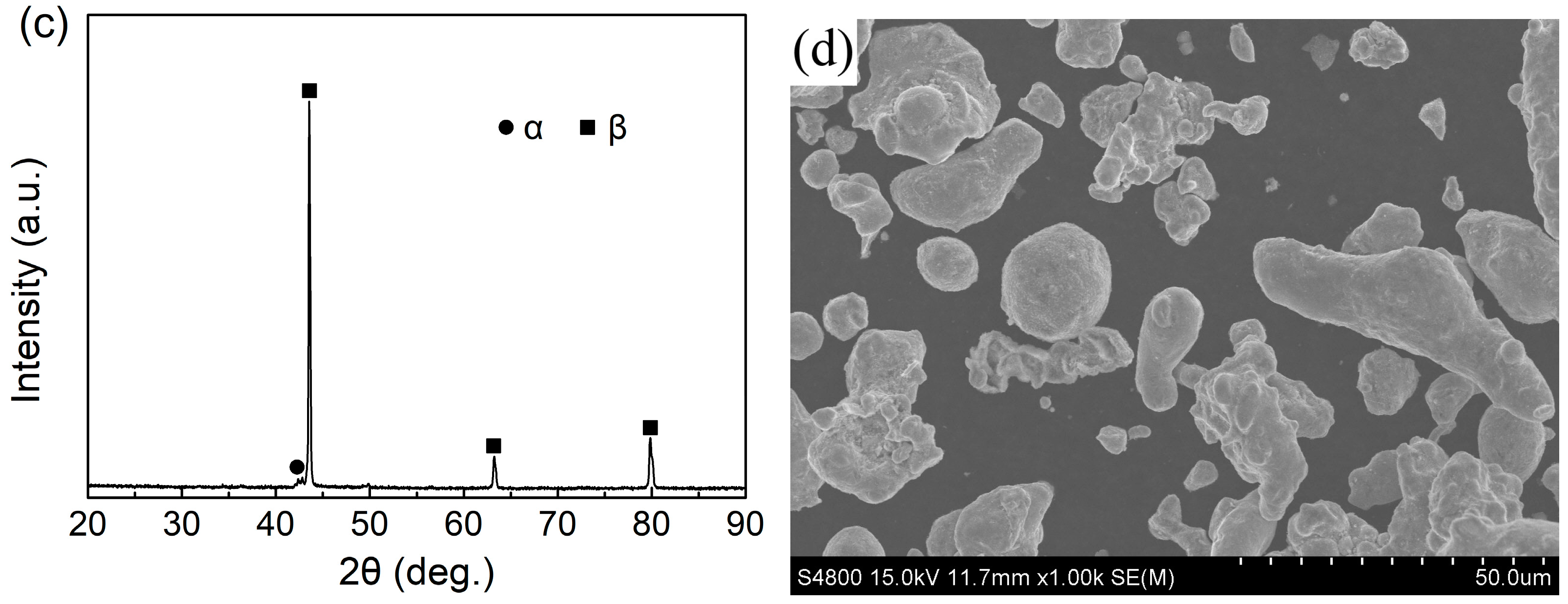
Figure 1 shows the XRD spectra and SEM images of the raw Ti3AlC2 powders and water-atomized Cu40Zn powders. Only diffraction peaks belonging to Ti3AlC2 are detected in Ti3AlC2 powders (Figure 1a), meaning its high phase purity. For water-atomized Cu40Zn powders, the β phase shows a much higher peak intensity than the α phase (Figure 1c), implying a much higher content of the β phase than the α phase. This can be attributed to the quick cooling speed of droplets during the water atomization process, suppressing the transformation of the β phase to the α phase according to the Cu-Zn phase diagram [22].
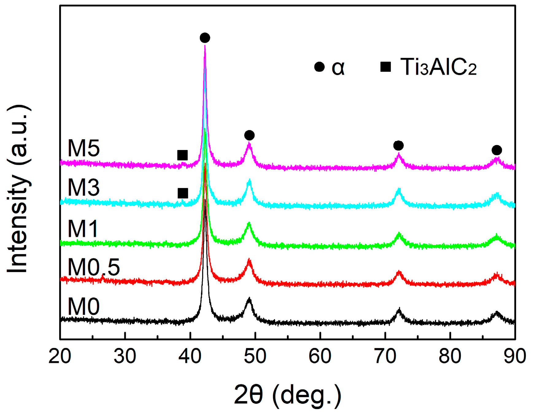
Figure 2 shows the XRD spectra of Cu40Zn-Ti3AlC2 powder mixtures after 10 h of milling. It can be seen that the diffraction peaks of the β phase disappeared, and except for Ti3AlC2 in samples M3 and M5, only peaks belonging to the α phase can be detected for all the ball-milled Cu40Zn-Ti3AlC2 powder mixtures. Actually, these α phases should be non-equilibrium supersaturated α phases, considering that the equilibrium phase constituent of Cu40Zn is α + β [22]. Significantly broadened diffraction peaks of these α phases imply significant grain refinement and serious lattice distortion. Grain boundaries and dislocations, introduced by mechanical energy during the high-energy milling process, supply positions for extra Zn atoms, promoting the transformation of a non-equilibrium β phase in water-atomized Cu40Zn to a supersaturated α phase.
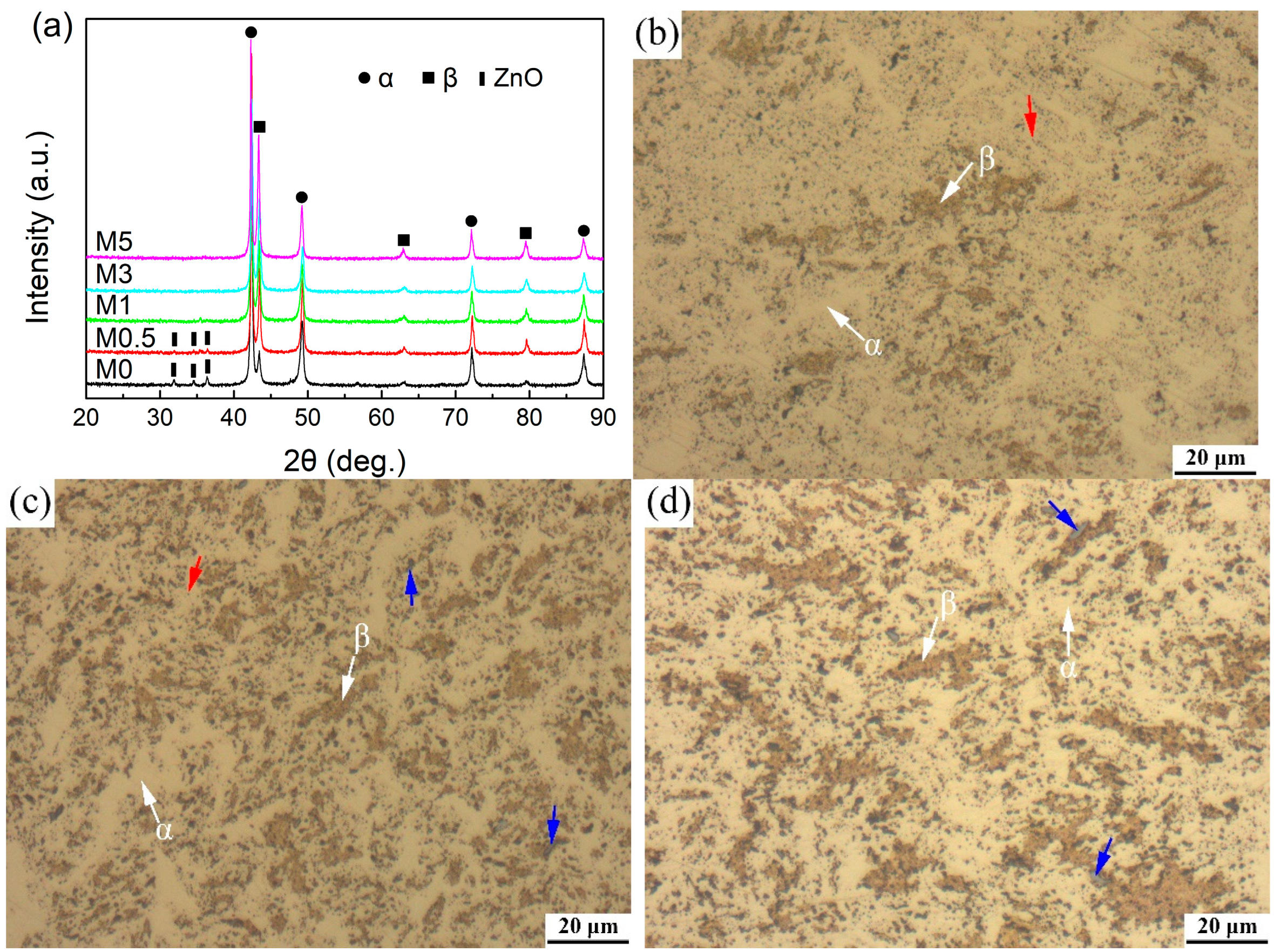
Figure 3 presents the XRD spectra and OM images of the sintered Cu40Zn-Ti3AlC2 composites. As shown in Figure 3a, diffraction peaks belonging to the α and β phases can be clearly detected for all samples and the peak intensity of the β phase increases with increasing content of the Ti3AlC2 additive. In addition, diffraction peaks of ZnO can be found in samples M0 and M0.5. As shown in Figure 3b–f, the OM observation confirms the presence of α and β phases in the sintered composites, where the latter is easily corroded by metallographic etchant and appears as a brown color. Black dots, indicated by the red arrows in Figure 3b,c, were mainly scattered in the α phase region of samples M0 and M0.5, and these are ZnO with a typical composition of 45.4O-47.4Zn-7.2Cu (at.%), measured by EDS analyses (the detection of a small amount of Cu should be attributed to the interference of the surrounding Cu matrix). Typical EDS results for the gray particles in samples M0.5, M1, M3 and M5, indicated by the blue arrows in Figure 3c–f, are 65.1C-5.0O-2.1Al-7.1Ti-11.6Cu-9.1Zn, 57.2C-12.3O-2.3Al-10.1Ti-10.9Cu-7.2Zn, 68.1C-6.5O-2.2Al-10.7Ti-8.6Cu-3.9Zn and 66.1C-3.1O-1.9Al-10.1Ti-11.3Cu-7.5Zn (at.%), respectively. Ti, Al and C can be found in these gray particles, indicating they are a Ti3AlC2-relevant phase, although the element percentage of the EDS results differs from the stoichiometric ratio of Ti3AlC2 due to the inaccuracy of C content analyzed by EDS. Moreover, Cu and Zn can be detected due to the interference of the surrounding CuZn matrix and the inner diffusion of Cu into Ti3AlC2. The O element absorbed by Ti3AlC2 during the high-energy milling and sintering processes can also be detected.
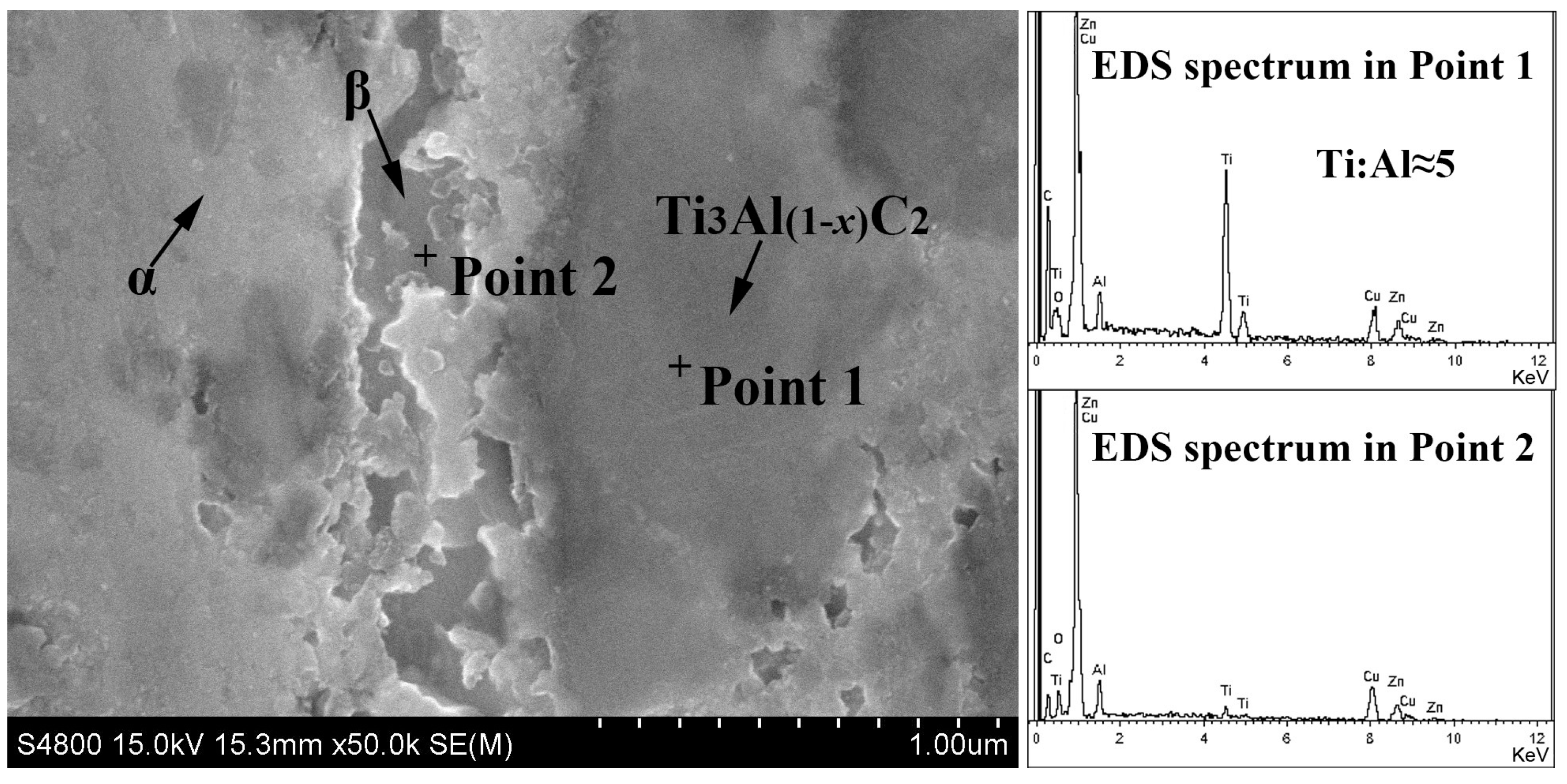
Figure 3g shows the changes in the α, β and ZnO contents as a function of the Ti3AlC2 additive through the semiquantitative interpretation of the XRD spectra in Figure 3a based on the adiabatic principle [23]. It can be seen that the contents of the α and ZnO phases decrease when increasing the Ti3AlC2 content from 0 to 5 wt.%; meanwhile, this is the opposite for the β phase, in accordance with the OM observation. The formation of ZnO can be attributed to the adsorbed oxygen during high-energy milling and hot-pressing, which oxidizes Zn selectively due to its higher activity. ZnO consumes the Zn element and decreases the content of the β phase subsequently. Meanwhile, the addition of Ti3AlC2 can adsorb oxygen, suppressing the formation of ZnO and promoting the formation of the β phase. Comprehensive studies have been carried out to reveal the structure stability of Ti3AlC2 in Cu-Ti3AlC2 composites and find that under high temperatures, Al can diffuse from Ti3AlC2 into Cu to form a Cu(Al) solid solution accompanied by the inner diffusion of Cu into Ti3AlC2 along the passway left by the Al vacancies [24,25,26]. This process is still true for present Cu40Zn-Ti3AlC2 composites, verified by the composition analyses as shown in Figure 4. It can be seen that the Ti:Al ratio in Ti3AlC2 is larger than 3; also, the surrounding α and β phases, especially for the β phase, are Al-containing, implying the outward diffusion of Al from Ti3AlC2 to surroundings. It is well known that Al has a zinc equivalent coefficient as high as 6 [27]. The outward diffusion of Al from Ti3AlC2 to its surroundings promotes the formation of the β phase, resulting in the increase in the β content with Ti3AlC2 additive.

3.2. Mechanical Properties

3.2.1. Hardness

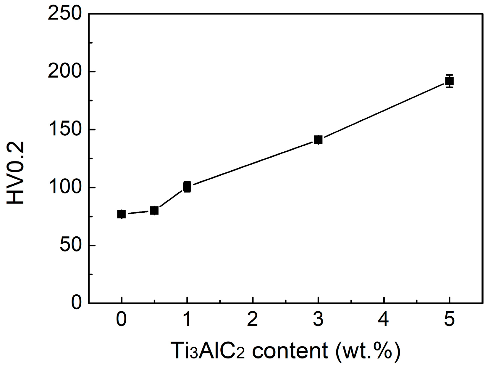
Figure 5 shows the change in hardness of Cu40Zn-Ti3AlC2 composites as a function of Ti3AlC2 content. It can be seen that the hardness increases almost linearly with increasing the Ti3AlC2 content from 0 to 5 wt.%. The evident increase in hardness can be attributed to four aspects: firstly, the suppression of the formation of soft ZnO by Ti3AlC2 absorbing oxygen; secondly, the strengthening effect of hard Ti3AlC2 similar to the functions of SiC in Al-Cu/SiC alloys [28] and Al7Cr and Al11Cr2 in Al-Mg-Ti-Cr alloys [29]; thirdly, the solid solution strengthening of Al in the α and β phases; finally, the increased hard β content in the composites triggered by the outward diffusion of Al from Ti3AlC2 to the surroundings.

3.2.2. Flexural Properties

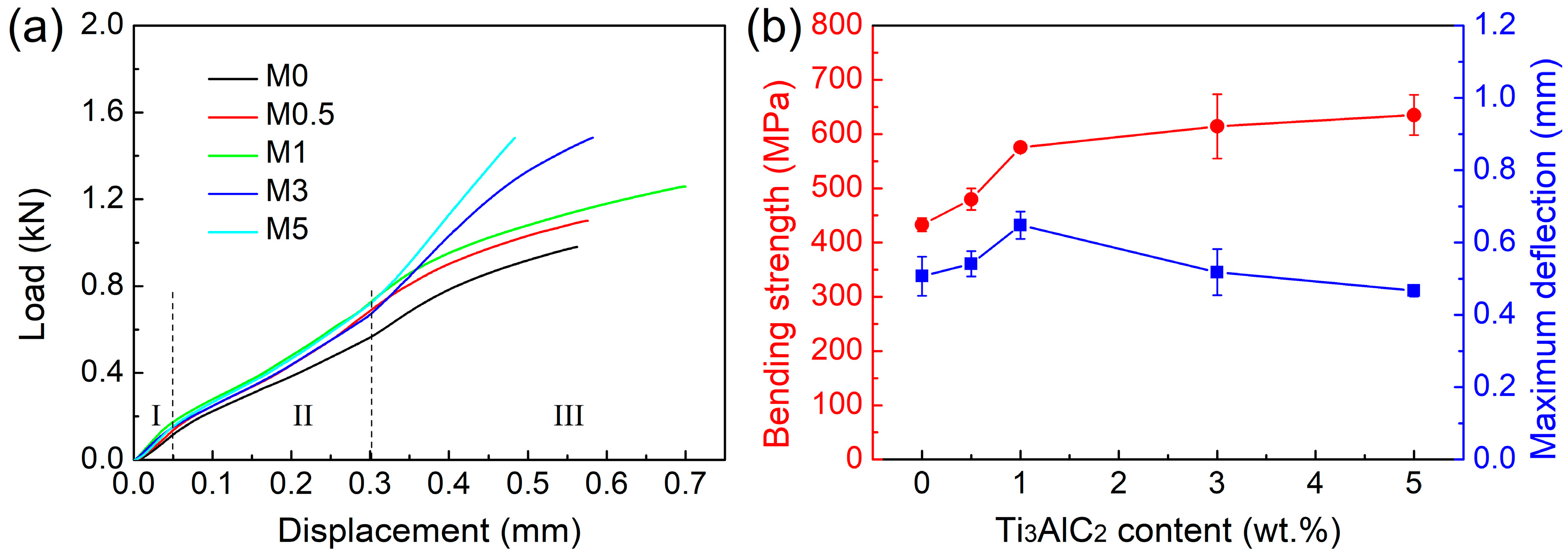
Bending tests are adopted to evaluate the strength and plasticity of Cu40Zn-Ti3AlC2 composites due to the restricted size of the sintered samples. Figure 6 shows the typical load–displacement curves for different samples. It can be seen that for all samples, the load–displacement curve can be divided into three stages. The first stage should be the transition process, including the elastic contact deformation of the crosshead and the adjustment deformation of the bending beam because the upper and lower surfaces of the beam are not strictly parallel to each other. The second stage should correspond to the elastic deformation process because of the linear relationship between the load and the displacement. The third stage should be the work hardening process implying the plastic deformation capacity of Cu40Zn-Ti3AlC2 composites except for sample M5. For sample M5, the linear relationship between the load and the displacement is extended until the breakage occurs.
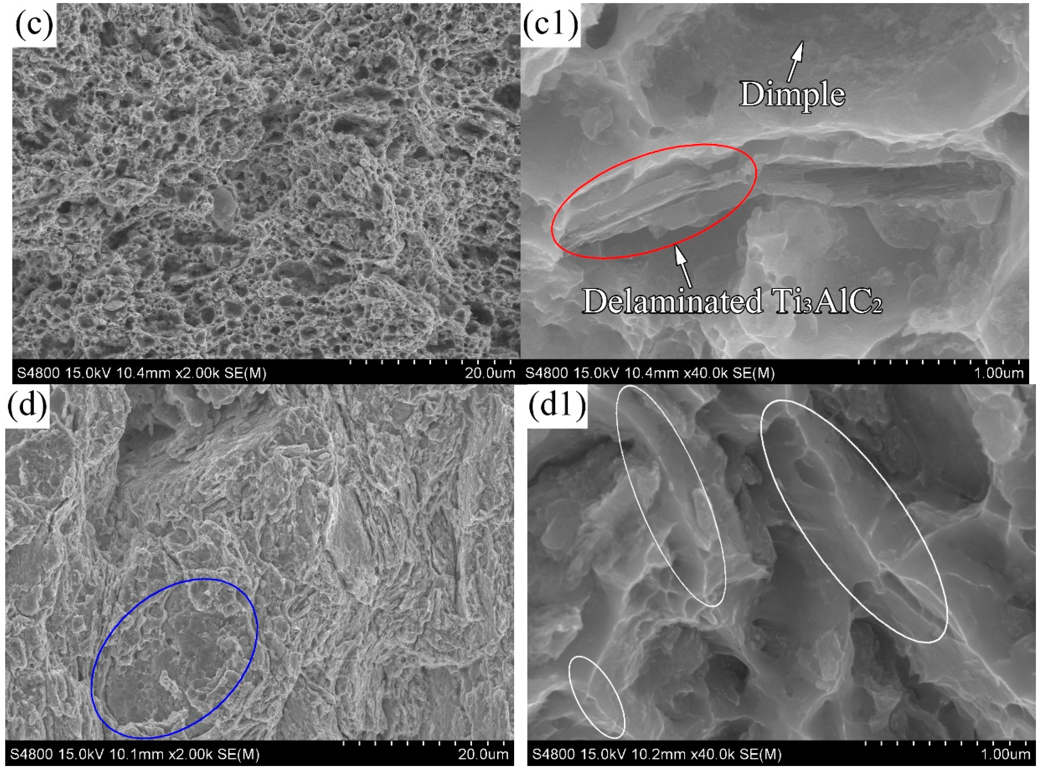
Figure 6b summarizes the flexural performances of different samples. It can be seen that by increasing the Ti3AlC2 content from 0 to 1 wt.%, both the strength and plasticity increase. Meanwhile, further increasing the Ti3AlC2 content to 5 wt.% leads to the increase in strength but imposes harm to the plasticity. Fracture appearances of typical samples are observed by the SEM to reveal the mechanisms of deformation and fracture, which are shown in Figure 7. For sample M0, as shown in Figure 7(a,a1), lots of dimples can be observed, which is in accordance with the fact that the ductile α phase plays a dominant role in the composite. However, it should be noted that plenty of particles, indicated by red arrows, can be found in the dimples. The EDS analyses confirm that these particles are ZnO. The ZnO particles, acting as cracking sources, promote the extensive formation of dimples and then the premature fracture of the sample, resulting in both poor strength and poor plasticity. For sample M0.5, as shown in Figure 7(b,b1), the reduction of the ZnO particles delays the initiation of dimples and enhances the strength and plasticity simultaneously. For sample M1, as shown in Figure 7(c,c1), extensive dimples can still be observed, implying the fine deformability of the composites. A higher β content, a solid solution strengthening effect and load bearing by Ti3AlC2 reinforcement contribute to the strength enhancement. It is worth noting that the delamination of Ti3AlC2, indicated by the red ellipse mark in Figure 7(c1), also contributes to the toughness improvement of the composite. However, as shown in Figure 7(d,d1), a distinct fracture appearance is observed for sample M5, in which extensive cleavage fracture (indicated by white ellipse marks) and hardly any dimples can be observed, reflecting its low plasticity. Moreover, some big Ti3AlC2 particles (indicated by a blue ellipse mark), presenting poor interfacial bonding with the Cu40Zn matrix, can also act as crack sources to promote the premature fracture of the composite.

3.3. Tribological Properties

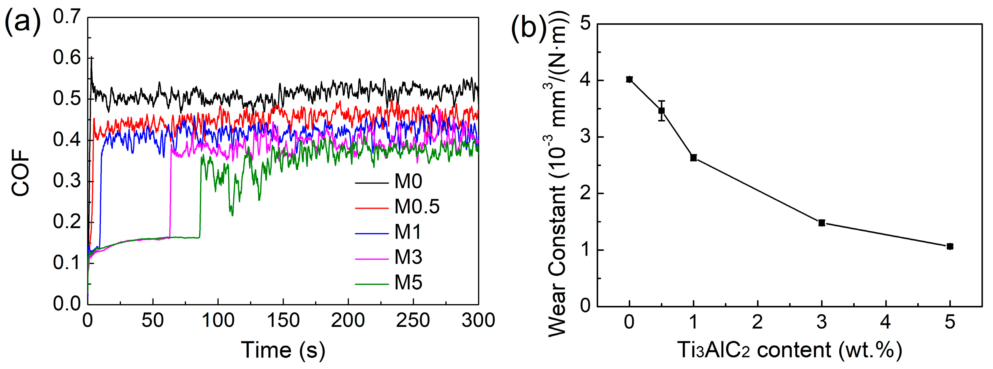
The coefficient of friction (COF) of different Cu40Zn-Ti3AlC2 composites changing with sliding time is plotted in Figure 8a. For samples M0 and M0.5, COF excursions to about 0.6 and 0.45, respectively, are found as soon as the testing starts, followed by a relatively steady stage. Meanwhile, for samples M1, M3 and M5, a running-in period with a COF of about 0.15 can be observed and the running-in period extends along with the increasing Ti3AlC2 content. After the running-in period, COF excursions are found in these samples and then followed by a relatively steady stage. The appearance of the running-in period and its extension should be attributed to the hardness enhancement with the increasing Ti3AlC2 content in Cu40Zn-Ti3AlC2 composites. During the steady stage, a fluctuation in COF for all samples can be found, reflecting the severe wear during this stage. In addition, it can be found that the COF during the steady stage decreases with the increasing Ti3AlC2 content. Two factors contribute to the decreasing COF. Firstly, according to previous research, the COF can be described as follows:
μ = S/H
where μ is the COF, S is the shear strength of the transferred film and H is the hardness of the substrate [30]. It can be seen that an increase in the hardness of the Cu40Zn-Ti3AlC2 composites stemming from the Ti3AlC2 reinforcement helps decrease the COF. Secondly, layered Ti3AlC2 can act as a solid lubricant to reduce the COF verified by a great deal of researches [31,32].
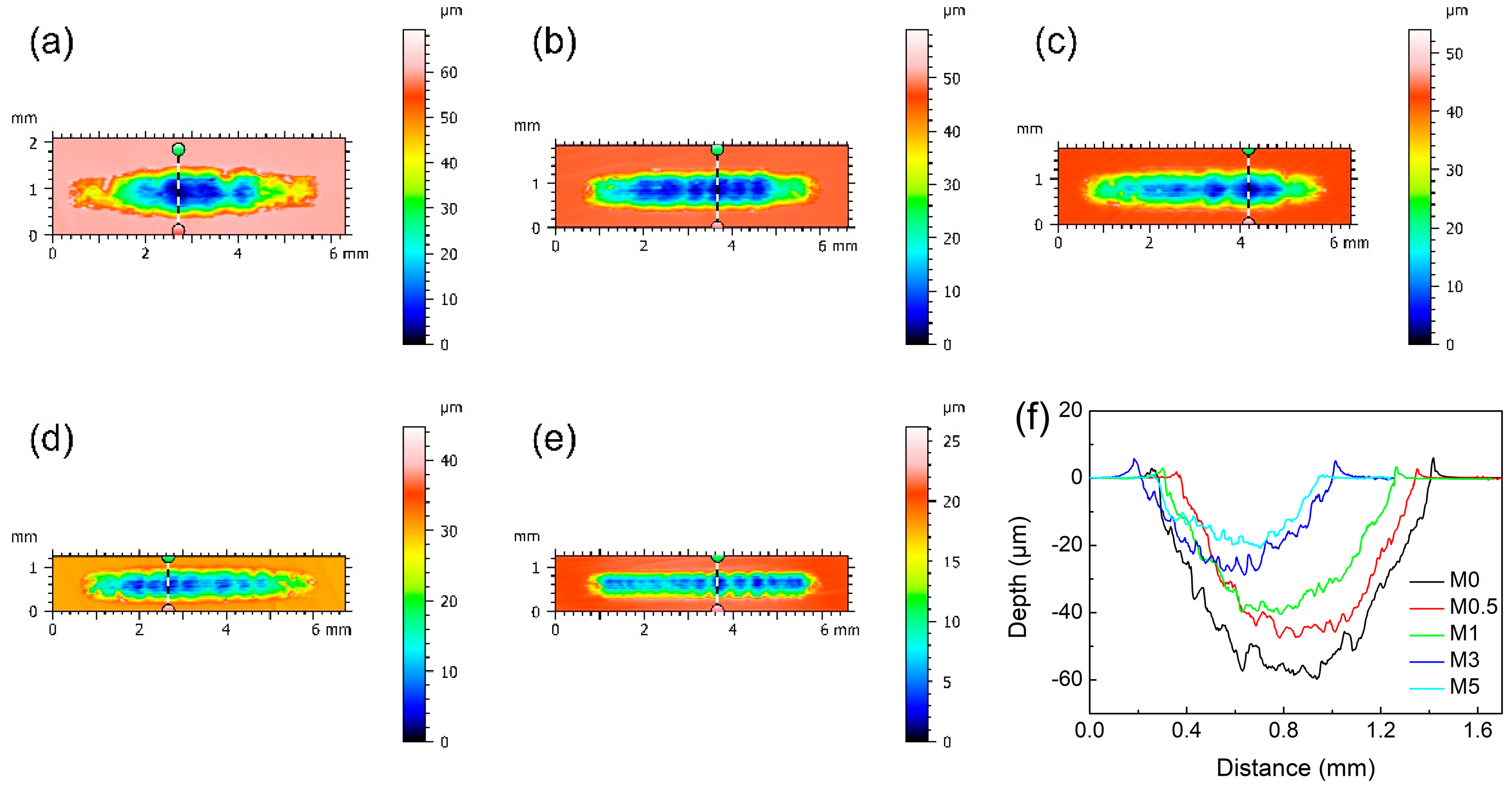
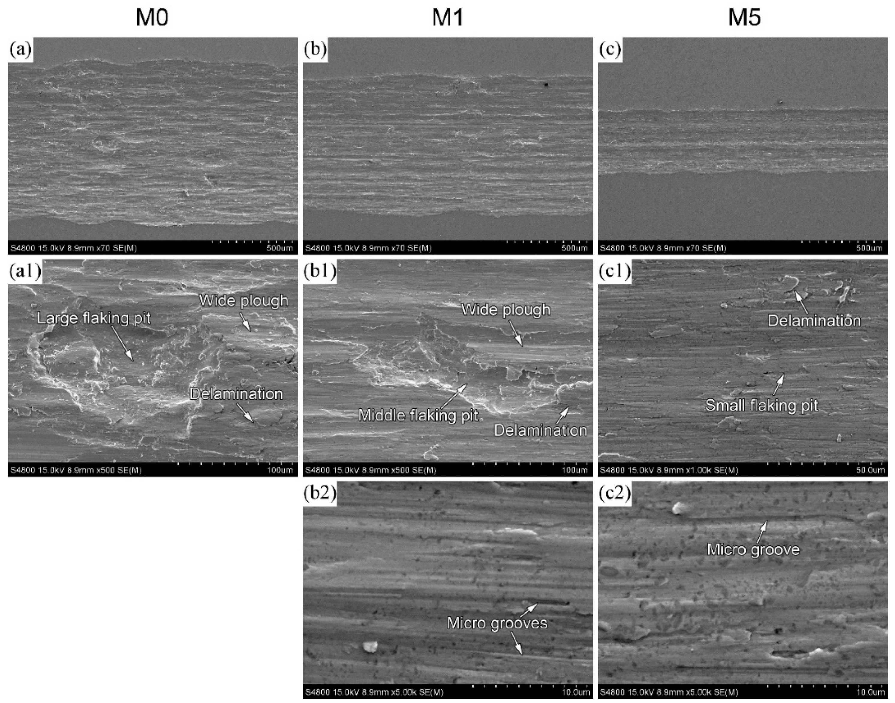
The wear constants of Cu40Zn-Ti3AlC2 composites as a function of Ti3AlC2 content are shown in Figure 8b. It can be seen that with the Ti3AlC2 content increasing from 0 to 3 wt.%, the wear constant presents an almost linear reduction from 4 × 10⁻³ to 1.5 × 10⁻³ mm3/N·m. Meanwhile, further increasing the Ti3AlC2 content to 5 wt.% just reduces the wear constant to 1.1 × 10⁻³ mm3/N·m. In general, the reduction in the wear constant should be ascribed to the hardness enhancement benefitting from the Ti3AlC2 additive. That is, the higher the hardness, the higher the wear resistance according to the Archard equation, which has been verified by other researches [33,34]. However, as shown in Figure 5, a still outstanding increase in hardness can be found in sample M5 compared with that of sample M3, which seems inconsistent with the slight reduction in wear constant of sample M5. This contradiction should be attributed to the enhanced abrasive wear process for sample M5 due to its harder abrasive particles as shown in Figure 10.
Figure 9 shows the typical wear track morphologies of different Cu40Zn-Ti3AlC2 composites, as well as the sectional profiles of the wear track fixed on the dotted lines. It can be seen that the higher the Ti3AlC2 content, the shallower and narrower the wear track, in accordance with the wear constant results. Moreover, it can be found that the surface of the wear track is rugged, maybe owing to the piling up of the wear debris between the grinding ball and the sample. This process contributes to avoiding direct contact between friction pairs, consequently reducing the wear degree in some regions and causing the fluctuation in the COF as shown in Figure 8a.
To reveal the underlying wear mechanism, the worn surfaces of the Cu40Zn-Ti3AlC2 composites and the corresponding counterparts are observed by SEM analyses, which are shown in Figure 10 and Figure 11, respectively. For sample M0, as shown in Figure 10(a,a1) and Figure 11(a,a1), big flaking pits, delaminations and wide ploughs can be found in the worn surface. Furthermore, large patches transferred from sample M0 are found attached to the counter-grinding ball. Delamination on the patches implies the dynamic process of stacking and peeling the transferred substance. Combining the characteristics of the worn surface and the counterpart, it can be concluded that the wear mechanism of sample M0 is mainly adhesive wear along with surface fatigue and two-body abrasive wear. During the reciprocating motion, sample M0 experiences severe plastic deformation due to its low hardness. Repeated plastic deformation leads to the initiation and propagation of fatigue cracks, verified by the delamination in the worn surface. Moreover, the friction heat promotes micro-welding between the deformed surface and the counterpart. Subsequent separation is often realized by the breakage occurring in the side of the sample due to its low strength, leaving flaking pits in the worn surface [35]. The peeling-off substance transferring to the counter balling will act as abrasive patches to plough the sample, leaving a wide plough on the worn surface. For sample M1, relatively small flaking pits, delamination, wide ploughs and micro grooves can be found in the worn surface as shown in Figure 10(b–b2). Compared with that of sample M0, smaller patches are found attached to the counter-grinding ball, in which micro grooves can also be observed in Figure 11(b,b1). Similar to that of sample M0, the wear mechanism of sample M1 contains adhesive wear, surface fatigue and two-body abrasive wear. The difference is that the degree of adhesive wear in sample M1 decreases due to its higher hardness and strength benefitting from a higher β and Ti3AlC2 content. Micro grooves in the worn surface and patches with its width and depth close to the size of Ti3AlC2 particles prove that the three-body abrasive wear process is enhanced for sample M1 with the Ti3AlC2 particles as abrasive particles. For sample M5, as shown in Figure 10(c–c2) and Figure 11(c,c1), extremely small flaking pits, delamination and micro grooves can be found in the worn surface. Much smaller patches with more micro grooves are found covering the counter-grinding ball incompletely. These features imply that adhesive wear is further reduced while abrasive wear is further strengthened for sample M5 due to its higher hardness and strength compared with sample M1.

4. Conclusions

Cu40Zn-Ti3AlC2 composites were fabricated by high-energy milling followed by hot-pressing sintering. The effects of the Ti3AlC2 content (0, 0.5, 1, 3, 5 wt.%) on the microstructure and mechanical properties were investigated. The conclusions are as follows:
(1) The sintered Cu40Zn-Ti3AlC2 composites are mainly composed of α and β phases. ZnO is found in samples M0 and M0.5, which can be suppressed by Ti3AlC2. The β content increases with the increasing Ti3AlC2 content due to the outward diffusion of the β-forming element Al from Ti3AlC2 to the surroundings.
(2) The hardness of Cu40Zn-Ti3AlC2 composites increases significantly with the increasing Ti3AlC2 content due to the suppression of soft ZnO, the strengthening effect of hard Ti3AlC2, the solid solution strengthening of Al and the increased hard β content.
(3) The flexural strength of Cu40Zn-Ti3AlC2 composites increases with the Ti3AlC2 content, while the plasticity increases first and then decreases. Proper Ti3AlC2 content can improve both the strength and plasticity of the composites by suppressing soft ZnO, bearing load during the deformation process and adjusting the contents of ductile α and strong β reasonably. Meanwhile, excessive Ti3AlC2 is harmful to the plasticity of the composites due to the high β content and its damage to the matrix continuity.
(4) The wear resistance of Cu40Zn-Ti3AlC2 composites increases with the Ti3AlC2 content benefitting from increased hardness and strength. Adhesive wear is the predominant worn mechanism for composites with low Ti3AlC2 content. Meanwhile, the contribution of abrasive wear increases with increasing Ti3AlC2 content.

Author Contributions

Methodology, J.W., Y.F., N.M. and V.L.; Validation, J.W., P.Y. and P.Z.; Formal analysis, C.L.; Investigation, F.P., S.Z., T.Y., L.W., Z.T. and X.Z.; Writing—original draft, T.Y.; Visualization, T.W.; Supervision, N.M. and V.L.; Project administration, V.L. All authors have read and agreed to the published version of the manuscript.

Funding

This research was funded by Zhejiang Provincial Natural Science Foundation of China: LQ22E010007 and LTZ20E020001; Wenling Key Research and Development Project: 2023G00007; the Open Fund of Zhejiang Provincial Key Laboratory for Cutting Tools: ZD202105; Zhejiang Provincial Science and Technology Innovation Training Program of University Undergraduates: 2022R436A009.

Data Availability Statement

The original contributions presented in this study are included in the article; further inquiries can be directed to the corresponding authors.

Conflicts of Interest

Liwei Wu was employed by the company Tiangong Aihe Co., Ltd. Xin Zhang was employed by the company Ningbo Boway Alloy Material Co., Ltd. The remaining authors declare that the research was conducted in the absence of any commercial or financial relationships that could be construed as a potential conflict of interest.

References

  1. Davis, J.R. Copper and Copper Alloys; ASM International: London, UK, 2001. [Google Scholar]
  2. Lipowsky, H.; Arpaci, E. Copper in the Automotive Industry; Wiley Interscience: Hoboken, NJ, USA, 2007. [Google Scholar]
  3. Zhang, X.; Ma, C.; Li, S.; Pan, D.; Zheng, F. Interface design of lead-free free-cutting titanium reinforced graphite brass composites and its effect on mechanical properties and cutting performance. Mater. Sci. Eng. A 2020, 774, 138909. [Google Scholar] [CrossRef]
  4. Johansson, J.; Alm, P.; M’Saoubi, R.; Malmberg, P.; Ståhl, J.-E.; Bushlya, V. On the function of lead (Pb) in machining brass alloys. Int. J. Adv. Manuf. Technol. 2022, 120, 7263–7275. [Google Scholar] [CrossRef]
  5. Vilarinho, C.; Davim, J.P.; Soares, D.; Castro, F.; Barbosa, J. Influence of the chemical composition on the machinability of brasses. J. Mater. Process. Technol. 2005, 170, 441–447. [Google Scholar] [CrossRef]
  6. Stavroulakis, P.; Toulfatzis, A.I.; Pantazopoulos, G.A.; Paipetis, A.S. Machinable Leaded and Eco-Friendly Brass Alloys for High Performance Manufacturing Processes: A Critical Review. Metals 2022, 12, 246. [Google Scholar] [CrossRef]
  7. Hsieh, C.-C.; Wang, J.-S.; Wu, P.T.-Y.; Wu, W. Microstructural development of brass alloys with various Bi and Pb additions. Met. Mater. Int. 2013, 19, 1173–1179. [Google Scholar] [CrossRef]
  8. Jang, Y.; Kim, S.; Han, S. Effect of misch metal on elevated temperature tensile ductility of the Cu-Zn-Bi alloy. Met. Mater. Trans. A 2005, 36, 1060–1065. [Google Scholar] [CrossRef]
  9. Joseph, B.; Barbier, F.; Aucouturier, M. Embrittlement of copper by liquid bismuth. Scr. Mater. 1999, 40, 893–897. [Google Scholar] [CrossRef]
  10. Adineh, M.; Doostmohammadi, H. Microstructure, mechanical properties and machinability of Cu–Zn–Mg and Cu–Zn–Sb brass alloys. Mater. Sci. Technol. 2019, 35, 1504–1514. [Google Scholar] [CrossRef]
  11. Atsumi, H.; Imai, H.; Li, S.; Kondoh, K.; Kousaka, Y.; Kojima, A. Fabrication and properties of high-strength extruded brass using elemental mixture of Cu–40% Zn alloy powder and Mg particle. Mater. Chem. Phys. 2012, 135, 554–562. [Google Scholar] [CrossRef]
  12. Doostmohammadi, H.; Moridshahi, H. Effects of Si on the microstructure, ordering transformation and properties of the Cu60Zn40 alloy. J. Alloys Compd. 2015, 640, 401–407. [Google Scholar] [CrossRef]
  13. Yang, C.; Ding, Z.; Tao, Q.C.; Liang, L.; Ding, Y.F.; Zhang, W.W.; Zhu, Q.L. High-strength and free-cutting silicon brasses designed via the zinc equivalent rule. Mater. Sci. Eng. A 2018, 723, 296–305. [Google Scholar] [CrossRef]
  14. Kondoh, K.; Imai, H.; Kosaka, Y.; Kojima, A.; Umeda, J. Machinable Cu-40Zn Composites Containing Graphite Particles by Powder Metallurgy Process. J. Met. 2009, 2009, 853092. [Google Scholar] [CrossRef]
  15. Li, S.; Imai, H.; Umeda, J.; Fu, Y.; Kondoh, K. Investigation of High-strength Lead-free Machinable Cu40Zn Duplex Graphite Brasses by Powder Metallurgy. Mater. Sci. Technol. 2016, 32, 1751–1756. [Google Scholar] [CrossRef]
  16. Zhuo, H.-C.; Tang, J.-C.; Xue, Y.-Y.; Ye, N. Preparation of lead-free free-cutting graphite brasses by graphitization of cementite. Trans. Nonferrous Met. Soc. China 2015, 25, 3252–3257. [Google Scholar] [CrossRef]
  17. Sun, Z.M. Progress in research and development on MAX phases: A family of layered ternary compounds. Int. Mater. Rev. 2013, 56, 143–166. [Google Scholar] [CrossRef]
  18. Salvo, C.; Chicardi, E.; Hernández-Saz, J.; Aguilar, C.; Gnanaprakasam, P.; Mangalaraja, R. Microstructure, electrical and mechanical properties of Ti2AlN MAX phase reinforced copper matrix composites processed by hot pressing. Mater. Charact. 2021, 171, 110812. [Google Scholar] [CrossRef]
  19. Zhang, J.; Zhou, Y.C. Microstructure, mechanical, and electrical properties of Cu–Ti3AlC2 and in situ Cu–TiCx composites. J. Mater. Res. 2011, 23, 924–932. [Google Scholar] [CrossRef]
  20. Zhao, H.; Feng, Y.; Qian, G.; Huang, X.; Guo, S.; Sun, X. Effect of Ti3AlC2 Content on Electrical Friction and Wear Behaviors of Cu–Ti3AlC2 Composites. Tribol. Lett. 2019, 67, 96. [Google Scholar] [CrossRef]
  21. Ying, P.; Sun, H.; Zhang, P.; Lin, C.; Yang, T.; Wu, J.; Huang, M.; Wang, T.; Lian, Z.; Levchenko, V. Preparation and tribological properties of WS2 solid lubricating coating with dense structure using HiPIMS. J. Mater. Res. Technol. 2024, 32, 530–540. [Google Scholar] [CrossRef]
  22. Kowalski, M.; Spencer, P.J. Thermodynamic reevaluation of the Cu-Zn system. J. Phase Equilibria Diffus. 1993, 14, 432–438. [Google Scholar] [CrossRef]
  23. Chung, F.H. Quantitative interpretation of X-ray diffraction patterns of mixtures. II. Adiabatic principle of X-ray diffraction analysis of mixtures. J. Appl. Crystallogr. 1974, 7, 526–531. [Google Scholar] [CrossRef]
  24. Zhang, J.; Wang, J.; Zhou, Y. Structure stability of Ti3AlC2 in Cu and microstructure evolution of Cu–Ti3AlC2 composites. Acta Mater. 2007, 55, 4381–4390. [Google Scholar] [CrossRef]
  25. Liang, S.; Zhai, H.; Ai, M.; Huang, Z. Fabrication and properties of Cu-Ti3AlC2 cermet. Rare Met. Mater. Eng. 2007, 36, 668–670. [Google Scholar]
  26. Liu, Y.; Tang, X.-H.; Zhou, S.-F.; Guo, B.-S.; Zhang, Z.-G.; Li, W. Improving mechanical properties of Cu/Ti3AlC2 composites via in-situ decomposed gradient interfaces. Mater. Sci. Eng. A 2022, 834, 142615. [Google Scholar] [CrossRef]
  27. Lu, J.P.; Li, X.H. Metallographic Atlas of Processed Copper and Copper Alloy; Central South University Press: Changsha, China, 2010. [Google Scholar]
  28. Keneshloo, M.; Paidar, M.; Taheri, M. Role of SiC ceramic particles on the physical and mechanical properties of Al–4%Cu metal matrix composite fabricated via mechanical alloying. J. Compos. Mater. 2016, 51, 1285–1298. [Google Scholar] [CrossRef]
  29. Razazi, H.A.; Paidar, M.; Ojo, O.O. Effect of Mn and Cr on structure and mechanical properties of Al-10%Mg-0.1%Ti alloy. Vacuum 2018, 155, 619–630. [Google Scholar] [CrossRef]
  30. Wu, Y.; Wang, F.; Cheng, Y.; Chen, N. A study of the optimization mechanism of solid lubricant concentration in Ni/MoS2 sellf-lubricating composite. Wear 1997, 205, 64–70. [Google Scholar] [CrossRef]
  31. Lian, W.; Mai, Y.; Wang, J.; Zhang, L.; Liu, C.; Jie, X. Fabrication of graphene oxide-Ti3AlC2 synergistically reinforced copper matrix composites with enhanced tribological performance. Ceram. Int. 2019, 45, 18592–18598. [Google Scholar] [CrossRef]
  32. Wang, S.; Zhu, S.; Cheng, J.; Qiao, Z.; Yang, J.; Liu, W. Microstructural, mechanical and tribological properties of Al matrix composites reinforced with Cu coated Ti3AlC2. J. Alloys Compd. 2017, 690, 612–620. [Google Scholar] [CrossRef]
  33. Paidar, M.; Ojo, O.O.; Ezatpour, H.R.; Heidarzadeh, A. Influence of multi-pass FSP on the microstructure, mechanical properties and tribological characterization of Al/B4C composite fabricated by accumulative roll bonding (ARB). Surf. Coatings Technol. 2019, 361, 159–169. [Google Scholar] [CrossRef]
  34. Paidar, M.; Bokov, D.; Mehrez, S.; Ojo, O.O.; Ramalingam, V.V.; Memon, S. Improvement of mechanical and wear behavior by the development of a new tool for the friction stir processing of Mg/B4C composite. Surf. Coatings Technol. 2021, 426, 127797. [Google Scholar] [CrossRef]
  35. Mazaheri, Y.; Bahiraei, M.; Jalilvand, M.M.; Ghasemi, S.; Heidarpour, A. Improving mechanical and tribological performances of pure copper matrix surface composites reinforced by Ti2AlC MAX phase and MoS2 nanoparticles. Mater. Chem. Phys. 2021, 270, 124790. [Google Scholar] [CrossRef]
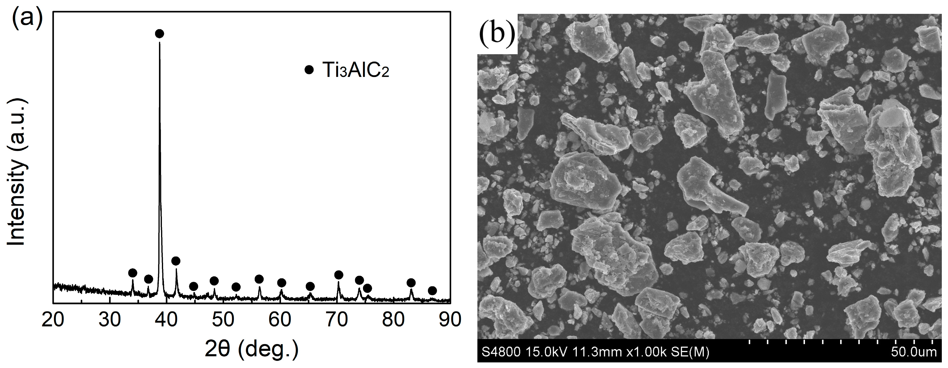
Figure 1. XRD spectra and SEM images of raw materials: (a,b) Ti3AlC2; (c,d) water-atomized Cu40Zn.
Lubricants 12 00306 g001aLubricants 12 00306 g001b
Figure 2. XRD spectra of Cu40Zn-Ti3AlC2 powder mixtures after 10 h of milling.
Lubricants 12 00306 g002
Figure 3. XRD spectra (a), OM images (bf) and phase content (g) of the sintered Cu40Zn-Ti3AlC2 composites: (b) M0; (c) M0.5; (d) M1; (e) M3; (f) M5.
Lubricants 12 00306 g003aLubricants 12 00306 g003b
Figure 4. SEM image and EDS spectra of sample M5.
Lubricants 12 00306 g004
Figure 5. Hardness of Cu40Zn-Ti3AlC2 composites as a function of Ti3AlC2 content.
Lubricants 12 00306 g005
Figure 6. Typical load–displacement curves (a) and flexural performances (b) of Cu40Zn-Ti3AlC2 composites.
Lubricants 12 00306 g006
Figure 7. SEM fractographs for Cu40Zn−Ti3AlC2 composites: (a,a1) M0; (b,b1) M0.5; (c,c1) M1; (d,d1) M5.
Lubricants 12 00306 g007aLubricants 12 00306 g007b
Figure 8. COF curves (a) and wear constant (b) of Cu40Zn-Ti3AlC2 composites.
Lubricants 12 00306 g008
Figure 9. Wear track morphologies (ae) and sectional profiles of the wear tracks (f) of Cu40Zn-Ti3AlC2 composites: (a) M0; (b) M0.5; (c) M1; (d) M3; (e) M5.
Lubricants 12 00306 g009
Figure 10. SEM images of the worn surfaces of the Cu40Zn-Ti3AlC2 composites: (a,a1) M0; (bb2) M1; (cc2) M5.
Lubricants 12 00306 g010
Figure 11. SEM images of the worn surfaces of the counterparts for (a,a1) M0; (b,b1) M1; (c,c1) M5.
Lubricants 12 00306 g011
Disclaimer/Publisher’s Note: The statements, opinions and data contained in all publications are solely those of the individual author(s) and contributor(s) and not of MDPI and/or the editor(s). MDPI and/or the editor(s) disclaim responsibility for any injury to people or property resulting from any ideas, methods, instructions or products referred to in the content.