Abstract
With the development of technical requirements, the current challenges faced by bearing materials mainly revolve around high-temperature conditions and the trend towards material lightweighting. Full ceramic bearings are the new candidate due to their excellent properties. This article details the tribological and adsorption performance of chlorophenyl silicone oil (CPSO) as a high-temperature lubricant in ceramic tribological systems (ZrO2, Al2O3, and Si3N4). Among the three ceramic tribological systems, the lubrication performance can be ordered as Si3N4 > Al2O3 > ZrO2, as the wear rates of the ZrO2 and Al2O3 tribo-systems are almost 1135.67 and 283.33 times larger than that of the Si3N4 tribo-system, respectively. The observed results can be explained by the superior adsorption performance of CPSO on a Si3N4 ceramic surface, which was calculated by molecular dynamic simulation. The molecular dynamic simulation results show the adsorption energy of CPSO/Si3N4 is almost 54.09 and 61.18 times higher compared to that on ZrO2 and Al2O3 ceramics. These findings provide experimental and theoretical insights for understanding the lubrication performance of CPSO in a full ceramic tribo-system.
1. Introduction
High-temperature bearings are key components of advanced devices, with their tribological performance being pivotal for the overall functionality of mechanical systems [1]. In military and manufacturing applications such as spacecraft, small drones, and high-speed machine tools, bearings typically operate in extreme conditions such as wide temperature range, high speed, and insufficient lubrication [2]. These extreme conditions push the working temperature of bearing materials to the limits of their thermal capacity. With the development of technical requirements, full ceramic bearings have been the new candidate due to their excellent performance at high speed, compression resistance, high/low temperature resistance, wear resistance, corrosion resistance, and electromagnetic insulation, as well as their smaller density compared with bearing steels [3,4,5].
Research on the tribological behavior of ceramic materials has yielded significant insights into friction mechanisms of full ceramic bearings and their effects on wear, operational performance, and life span [6]. Sun et al. studied the temperature distribution in lubricated ceramic bearings by comparing experimental data with established models. Their results showed that the effect of bearing speed on temperature rise tends to decrease when the bearings are under heavy load conditions. Under high-speed conditions, the temperature rise tends to increase with the load [7]. Yao et al. further explored the optimal oil supply for fully ceramic bearings under oil lubrication. Compared to the load, the speed of the bearing is the critical factor of the optimal oil supply [8]. Yuan et al. studied the influence of lubricants’ viscosity on the temperature increment and vibration of hybrid ceramic ball bearings. Their research revealed the presence of an optimal viscosity that effectively reduces both vibration and temperature rise in hybrid ceramic ball bearings [9]. Yan et al. investigated the effects of water lubrication on the operational performance of ceramic ball bearings by establishing a high-speed lubrication model. This model considers the structural characteristics of the bearings, the state of high-speed turbulence, thermal effects, and elastic deformation [10]. Han et al. analyzed the formation of the lubricant film on the bearing raceway surface under the coupled effect of hydrodynamics and boundary lubrication [11]. Sun Jian studied the characteristics of the lubricant film thickness of full ceramic ball bearings and found that the lubricant film thickness becomes thicker with the increase in bearing speed and decreases with the increase in bearing load [12]. Huang and Liu established a thermoelastic hydrodynamic lubrication mathematical model for ceramic ball bearings and found that the lubricant film of ceramic ball bearings has a higher load carrying capacity than that of steel bearings under the same operating parameters [6].
Besides the research of materials, lubricants also face the issue of lubrication failure at high temperatures. This is mainly due to the decrease in viscosity at high temperatures, which prevents the formation of a stable lubricating film. CPSO, with its excellent viscosity–temperature performance, shows promise as part of a new generation of high-temperature lubricants. Scholarly focus has predominantly been on enhancing its high-temperature and boundary lubrication capabilities [13,14]. Structural modifications, such as high phenyl substitution, have notably enhanced the resistance of silicone oil to oxidation, thermal degradation, and radiation effects [15,16]. Studies by Weng et al. about the tribological properties of chlorophenyl silicone oil (CPSO) showcased their advantages in the steel/CuSn alloy condition, attributed to the FeCl2 tribofilm in the rubbing process, effectively reducing wear and friction [17]. Additionally, Jiang et al. improved the lubricating performance of fluorosilicone oil by incorporating chlorine atoms into its side chain, enhancing extreme pressure performance and resistance to oxidative degradation under high temperature while maintaining non-corrosiveness to metals [18]. Wen et al. achieved high-temperature superlubricity with CPSO on the hydroxylated SiO2 surface generated by H+-ion running-in, highlighting its potential for high-temperature lubrication applications [19]. However, its performance and mechanism in full ceramic bearings remains an area for further exploration.
In this study, the tribological results were carried out to compare the lubrication performance of CPSO in the three ceramic materials. The computed adsorption energy of CPSO molecules on the three ceramic surfaces can explain the mechanism of tribological performance of CPSO. Such findings provide experimental and theoretical insights for the application of CPSO and the material selection of a full Si3N4 ceramic tribo-system.
2. Materials and Methods
The ceramic materials (ZrO2, Al2O3, Si3N4) utilized in this study were commercially obtained from Sinoma Advanced Nitride Ceramic Co. Ltd. Shandong, China. The properties of the three ceramics are listed in Table 1. CPSO was available from the Sinopec Great Wall Technology Lubricating CO. Ltd. Chongqing, China. Additionally, all organic solvents (petroleum ether, acetone, anhydrous ethanol) employed were of analytical reagent grade and purchased from Shanghai Aladdin Biochemical Technology Co., Ltd., Shanghai, China.

Table 1.
The properties of the three ceramics.
Tribological measurements in this research were conducted by a high-temperature reciprocating tribometer (SRV-4, Optimol, Munich, Germany). The objective of the ball-on-disc tribological experiments is shown in Figure 1. The experimental setup consisted of an upper ball (diameter 10.3 mm, surface roughness RaZrO2 = 8 nm, RaAl2O3 = 6 nm, RaSi3N4 = 5 nm) and a ceramic disc (Φ24 mm × 7.88 mm). The test condition was set to 50 Hz, a 1 mm stroke, and 60 min duration, under a normal load of 50 N (resulting in a Hertz contact pressure of 1.71–2.45 GPa). Temperatures of 25 °C, 150 °C, and 250 °C were chosen to replicate the severe conditions of a high-temperature environment. The wear rates of the samples were calculated using the following equation: R = V/N × S, where R is the wear rate (mm3/Nm), V is the wear volume (mm3), N is the normal load (N), and S is the sliding distance (m). Prior to testing, ceramic discs were ultrasonically cleaned in anhydrous ethanol, petroleum ether, and acetone for 15 min.
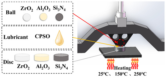
Figure 1.
Schematic diagram of tribometer.
To ensure uniformity in the experimental setup, both the ball and disc were replaced after each individual test. The entire experimental procedure was replicated thrice to ensure the consistency and reliability of the data obtained. Once the test finished, all used discs and balls were cleaned as mentioned before. Subsequently, these components were dried and stored for later characterization.
A rheometer (MCR301, Anton Paar, Graz, Austria) was used to measure the viscosity of CPSO at various temperatures. After each tribology test, the wear scar of the ceramic disc and wear scar of the upper ball were examined using an optical microscope (VHX6000, Keyence, Osaka, Japan). The wetting effects of CPSO on various ceramic surfaces were verified through contact angle measurements (OCA25, Dataphysics, Filderstadt, Germany). The wear rates of the wear scars on the ceramic discs were determined using a Zygo interferometer (New View 8300, Zygo, CT, USA). Additionally, the micro-topography of the tribo-pair was analyzed by a scanning electron microscope (SEM, Quanta 200, FEI, MT, USA) with an accelerating voltage of 15 kV. The element distribution of the wear scar surface was characterized by energy-dispersive spectroscopy (EDS, Genesis xm-2, EDAX, CA, USA). X-ray photoelectron spectroscopy (XPS, AXIS Supra, Kratos, UK) with Al Kα as a radiation source and 150 eV pass energy over a spot size of 200 µm was employed to understand the chemical state of the wear scar. The spectra of O 1s, Si 2p, C 1s, Al 2p, and Zr 3d were tested for further surface analysis. The binding energy of C 1s (284.8 eV) was used for the calibration of other elements.
The low-energy adsorption sites and adsorption energies of CPSO on the surface of different ceramics (ZrO2, Al2O3, Si3N4) were calculated using Monte Carlo adsorption of the molecular dynamic software (Material Studio 2020) [20,21]. First of all, the crystal cell of each ceramic was directly imported from the software structure. All 3D lattices were built in 36 Å × 36 Å with three layers of thickness. Afterward, the active surface of each ceramic primary cell was calculated by the Morphology module. The active planes were cleaved, and then, in the crystal, we added a 100 Å vacuum layer before the Monte Carlo adsorption simulation. Molecular interactions and intermolecular potentials were calculated using the COMPASS III force field. To minimize the system energy, the initial adsorption configuration was geometrically optimized based on the smart algorithm, and the collection tolerance was 1 × 10⁻⁴ kcal/mol and 5 × 10⁻³ kcal/mol/Å. The surface layer was set to the target atom for adsorption. Then, CPSO adsorption on three ceramic surfaces was performed by Monte Carlo adsorption simulations. After optimizing the geometry of the final system, energy calculations were conducted by the Dmol3 module to obtain the highest occupied molecular orbital (HOMO) and the lowest unoccupied molecular orbitals (LUMOs). A detailed explanation of the Monte Carlo search theory, including the fundamental formula, is in the supporting information.
3. Results
Figure 2a illustrates a molecular model of CPSO, highlighting the substitution of a methyl function on the silicone oil molecule with a chlorophenyl group. Figure 2b presents the viscosity variation of CPSO across a range of temperatures from 25 °C to 250 °C. The data show that the rate of decrease in CPSO’s viscosity diminishes as temperature increases, suggesting favorable viscosity–temperature characteristics. The other physical properties of CPSO are shown in Table 2.
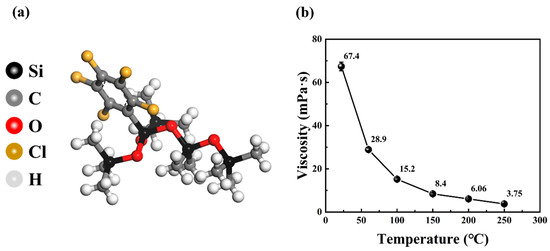
Figure 2.
(a) The molecular model of CPSO and (b) the viscosity result of CPSO at various temperatures.

Table 2.
The physical properties of CPSO [17].
Three different ceramic materials (ZrO2, Al2O3, and Si3N4) were tested, resulting in nine tribo-pairs. These pairs were categorized into three tribo-systems based on the material of the upper ball.
Figure 3 shows the coefficient of friction curves of a ZrO2 ceramic ball sliding against different ceramic discs separately. The coefficient of friction curves of ZrO2/ZrO2 and ZrO2/Si3N4 at 150 °C and 250 °C and ZrO2/Al2O3 at 250 °C are missing due to lubrication failure. In the ZrO2 ceramic tribo-system, the running-in duration exhibits significant variability across different friction pair configurations. The running-in period for a ZrO2 ceramic with itself is recorded at 658 s. In contrast, the running-in time for ZrO2/Al2O3 is 600 s at 150 °C and 200 s at 25 °C. Notably, the longest running-in time is observed with ZrO2/Si3N4, reaching 2100 s at 25 °C. An analysis of the COF curve, as illustrated in Figure 3, demonstrates that the lubrication performance within the ZrO2 ceramic system is comparatively suboptimal. At temperatures exceeding 150 °C, only the ZrO2/Al2O3 tribological pair uniquely achieves a COF of 0.19, indicative of effective lubrication. In contrast, the COFs for the other five friction pairs tested are above 0.8, indicating a failure in lubrication. At the lower temperature of 25 °C, the ZrO2 shows a better lubrication performance, with COFs of 0.14 for ZrO2/ZrO2, 0.17 for ZrO2/Al2O3, and 0.13 for ZrO2/Si3N4. Above all, these results suggest that the ZrO2/Al2O3 tribological pair is particularly effective in the ZrO2 ceramic system.
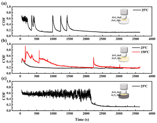
Figure 3.
The coefficient of friction curves of CPSO under (a) ZrO2/ZrO2, (b) ZrO2/Al2O3, (c) ZrO2/Si3N4 ceramic tribo-systems at 25 °C, 150 °C.
Figure 4 and Figure 5 show the coefficient of friction curves of Al2O3 and Si3N4 ceramic systems. Obviously, the COF curves exhibit two-stage (running-in period and steady-state) frictional behavior. Due to the wear of the surface and the increase in the contact area, the friction coefficient gradually decreases with the rubbing process. However, when the friction coefficient reaches a peak value, it drops and then enters into a stable state. This phenomenon, termed “friction self-organization”, is due to the self-adjusting of the two contact surfaces as a result of the complex interaction of wear, relaxation, and other factors [22].
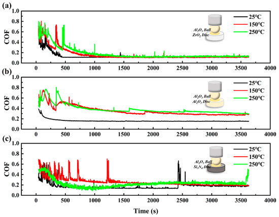
Figure 4.
The coefficient of friction curves of CPSO under (a) Al2O3/ZrO2, (b) Al2O3/Al2O3, (c) Al2O3/Si3N4 ceramic tribo-systems at 25 °C, 150 °C, and 250 °C.
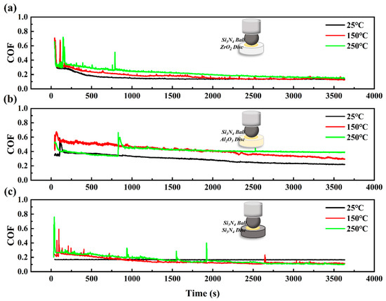
Figure 5.
The coefficient of friction curves of CPSO under (a) Si3N4/ZrO2, (b) Si3N4/Al2O3, (c) Si3N4/Si3N4 ceramic tribo-systems at 25 °C, 150 °C, and 250 °C.
In the Al2O3 ceramic system, a consistent running-in duration is observed across three ceramic tribological pairs, with an average duration of approximately 400 s. Notably, for Al2O3 tribo-pairs, the running-in time displays a temperature-dependent variation. It is 300 s at elevated temperatures of 150 °C and 250 °C but reduces to 100 s at the lower temperature of 25 °C. An analysis of the COF curve, as illustrated in Figure 4, indicates that the lubrication performance of the Al2O3 ceramic system is superior to that of the ZrO2 ceramic system, as evidenced by shorter running-in periods and a consistently steady COF curve. The COF curve for the Al2O3 ceramic system typically shows a steady decline throughout the experimental process, with a notable exception in the Al2O3/Si3N4 tribological pair, where a significant increase in COF is observed at 3612 s. In conclusion, the Al2O3/ZrO2 tribological pair exhibits the most effective lubrication performance within the Al2O3 ceramic system.
In the Si3N4 ceramic system, a further reduction in running-in duration is shown in Figure 5. Notably, when Si3N4 is against the ZrO2 disc, the running-in time is recorded at 180 s. For the Si3N4 against the Al2O3 disc, the running-in period reduces to 130 s, while the Si3N4/Si3N4 tribological pair shows the shortest running-in duration at 90 s. The analysis of the COF curve, as depicted in Figure 5, reveals that the lubrication performance within the Si3N4 ceramic system is the best among the three tested systems due to its stable and minimal COF. The COF curves for all three Si3N4 tribo-pairs exhibit relative stability and a consistent downward trend across different temperature ranges. In summary, within the nine ceramic tribological systems examined, the Si3N4/Si3N4 pairing stands out for its superior lubrication performance.
Figure 6 shows the WSD and WSS of the ZrO2 ceramic tribo-system observed by an optical microscope. The results from Figure 6 indicate that all the WSDs and WSSs increase as temperature increases from 25 °C to 250 °C.
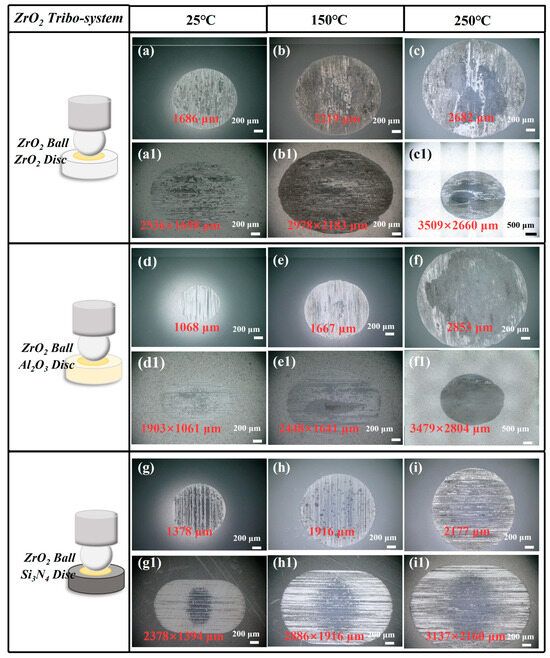
Figure 6.
(a–i) Wear scar of ZrO2 ball and (a1–i1) ceramic disc under CPSO as lubricant at 25 °C, 150 °C, and 250 °C with ZrO2 ceramic tribo-system.
The WSD observed in the ZrO2/ZrO2 tribo-pair exhibited a significant increase from 1686 μm at 25 °C to 2982 μm, representing an increase of 76.87%. Similarly, in the ZrO2/Al2O3 tribo-pair, the WSD escalated from 1068 μm at 25 °C to 2853 μm, marking an increase of 167.13%. Furthermore, the WSD for the ZrO2/Si3N4 tribo-pair rose from 1378 μm at 25 °C to 2177 μm, which constitutes an increase of 57.98%.
Figure 7 shows the WSD and WSS of the Al2O3 ceramic tribo-system observed by an optical microscope. The results from Figure 7 indicate that all the WSDs and WSSs increase as temperature increases from 25 °C to 250 °C.
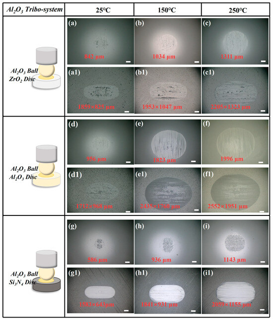
Figure 7.
(a–i) Wear scar of Al2O3 ball and (a1–i1) ceramic disc under CPSO as lubricant at 25 °C, 150 °C, and 250 °C with Al2O3 ceramic tribo-system; all scale bars are 200 μm.
The WSD of the Al2O3/ZrO2 tribo-pair increased from 842 μm at 25 °C to 1311 μm, representing a growth of 55.70%. In the case of the Al2O3/Al2O3 tribo-pair, the WSD escalated from 956 μm at 25 °C to 1996 μm, an increase of 108.79%. Furthermore, the WSD for the Al2O3/Si3N4 tribo-pair rose from 586 μm at 25 °C to 1143 μm, constituting an increase of 95.05%.
Figure 8 shows the WSD and WSS of the Si3N4 ceramic tribo-system observed by an optical microscope. The results indicate that all the WSDs and WSSs increase as temperature increases from 25 °C to 250 °C.
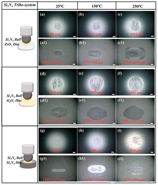
Figure 8.
(a–i) Wear scar of Si3N4 ball and (a1–i1) ceramic disc under CPSO as lubricant at 25 °C, 150 °C, and 250 °C with Si3N4 ceramic tribo-system; all scale bars are 200 μm.
The WSD of the Si3N4/ZrO2 tribo-pair demonstrated a growth from 688 μm at 25 °C to 1016 μm, representing an increase of 47.67%. In the case of Si3N4/Al2O3, the WSD rose from 1218 μm at 25 °C to 1502 μm, marking an increase of 23.32%. Notably, the WSD for the Si3N4/Si3N4 combination escalated dramatically from 230 μm at 25 °C to 850 μm, a substantial increase of 269.57%.
Figures S1–S3 depict the wear scar depth profile curves for both the ball and disc components in three distinct types of ceramic tribo-pairs. An observable trend across all tribo-pairs is the positive correlation between wear scar depth and temperature. Notably, the Si3N4/Si3N4 friction pair system consistently exhibits the smallest wear scar depth among the pairs studied. In contrast, the ZrO2/Al2O3 tribo-pair system demonstrates the greatest wear scar depth.
The wear volume of the ceramic discs was measured by a white light interferometer. The calculated wear rate of the ceramic disc is shown in Figure 9.

Figure 9.
Wear rate of (a) ZrO2 ceramic disc, (b) Al2O3 ceramic disc, and (c) Si3N4 ceramic disc under CPSO as lubricant at 25 °C, 150 °C, and 250 °C.
Analysis of Figure 9a reveals that the trend in wear rate is consistent with that of the WSD. A notable increase in wear rate is observed with rising temperatures. Specifically, for the ZrO2/ZrO2 tribo-pair, the wear rate escalated from 2.45 × 10⁻⁶ mm3/Nm at 25 °C to 1.06 × 10⁻⁵ mm3/Nm, signifying an increase of 332.65%. In the case of ZrO2/Al2O3, the wear rate increased from 7.62 × 10⁻⁷ mm3/Nm at 25 °C to 2.04 × 10⁻⁵ mm3/Nm, a substantial increase of 2577.16%. For the ZrO2/Si3N4 tribo-pair, the wear rate initially rose from 1.95 × 10⁻⁷ mm3/Nm to 2.82 × 10⁻⁷ mm3/Nm, an increase of 44.62%, and then subsequently decreased to 1.73 × 10⁻⁷ mm3/Nm.
In the Al2O3 tribo-system, as shown in Figure 9b, the wear rate of the Al2O3/ZrO2 tribo-pair significantly escalated, moving from 9.42 × 10⁻⁸ mm3/Nm at 25 °C to 9.98 × 10⁻⁷ mm3/Nm, which represents an increase of 959.45%. For the Al2O3/Al2O3, there was a marked increase in wear rate from 6.38 × 10⁻⁷ mm3/Nm at 25 °C to 9.36 × 10⁻⁶ mm3/Nm, a substantial growth of 1367.01%. In the case of the Al2O3/Si3N4 tribo-pair, the wear rate rose from 1.18 × 10⁻⁷ mm3/Nm to 6.98 × 10⁻⁷ mm3/Nm, an increase of 491.53%.
In the Si3N4 tribo-system, as shown in Figure 9c, the wear rate of the Si3N4/ZrO2 tribo-pair exhibited a significant increase, rising from 7.80 × 10⁻⁸ mm3/Nm at 25 °C to 3.41 × 10⁻⁷ mm3/Nm, representing an increase of 337.18%. For the Si3N4/Al2O3, there was a slight increase in wear rate from 1.14 × 10⁻⁶ mm3/Nm at 25 °C to 1.79 × 10⁻⁶ mm3/Nm, marking a growth of 57.02%. In the case of the Si3N4/Si3N4 tribo-pair, the wear rate escalated from 1.35 × 10⁻⁹ mm3/Nm to 1.54 × 10⁻⁷ mm3/Nm, a dramatic increase of 11,307.41%.
The results of the tribological tests about three tribo-systems are summarized in Table 3. It can be deduced from the study that wear rates across various tribo-pairs exhibit different performances. All the tribo-pairs show a general trend of positive correlation with temperature. Among the systems analyzed, the ZrO2 system demonstrates the least effective lubrication, whereas the Si3N4 system exhibits the most optimal lubrication performance due to the stable COF and smallest wear rate.

Table 3.
Tribological results of nine tribo-pairs at tested temperatures.
4. Discussion
To reveal the wear mechanism of CPSO lubrication with the ceramic system at high temperature, the SEM results of the worn surfaces are shown in Figure 10a–f.
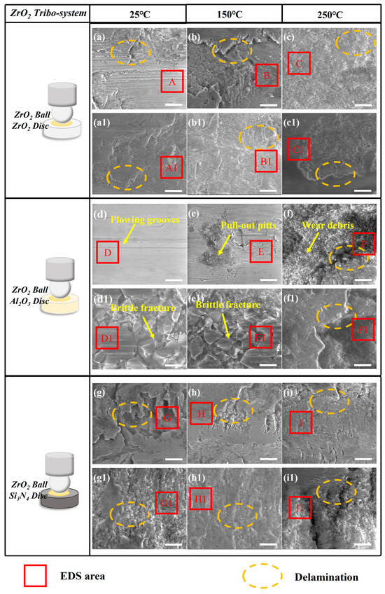
Figure 10.
The SEM results of (a–i) the ZrO2 ceramic ball, (a1–c1) ZrO2 ceramic disc, (d1–f1) Al2O3 ceramic disc, and (g1–i1) Si3N4 ceramic disc under CPSO as a lubricant at 25 °C, 150 °C, and 250 °C; the relative movement direction of the mated interface is horizontal in each picture; all the scale bars are 10 μm.
Analysis of the SEM results reveals that within the ZrO2 system, with the surfaces of the ZrO2/ZrO2 tribo-pair, both of the wear scars show lots of fatigue cracking and delamination. The surfaces of the Si3N4 discs exhibit minor plowing grooves, extensive delamination, and evidence of ceramic fatigue cracking, as marked in Figure 10. However, other ceramic discs’ observed wear morphologies predominantly comprise extensive delamination and abrasive particles, suggesting that wear was mainly caused by significant plastic deformation and micro-welding at the ceramic surfaces. Before material transfer occurred, surface fatigue and the formation of wear debris were likely present. Consequently, the primary wear mechanisms in this system are plastic deformation, fatigue cracking, and material transfer. Additionally, an increase in the intensity of material transfer is observed as temperatures rise from 25 to 250 °C, characterized by more pronounced material transfer and a greater presence of abrasive particles, as shown in Figure 10(c,c1,f,f1,i,i1). The EDS results indicate that the main component of these layers is the material transfer between mating surfaces. The EDS spectra corresponding to the marked areas are presented in Table S1.
In the Al2O3 tribo-system, as shown in Figure 11, ceramic fatigue wear was predominantly identified on the discs of ZrO2. For Al2O3 discs within this system, the observed surface characteristics included plowing grooves, ceramic fractures indicative of fatigue wear, and material pull-out pits. These observations suggest that the principal wear mechanisms in the Al2O3/Al2O3 tribo-pair are primarily fatigue wear and abrasive wear. For Si3N4 discs within this system, slight plowing grooves were only observed on the Si3N4 discs. In the main components of the wear scar of the Al2O3 system, except the elements of Al2O3 disc, there is no evidence of the transfer of mating materials, indicating that there was no serious transfer of wear materials and the main morphological characteristics observed for the material fatigue were caused by ceramic fatigue cracking and abrasive wear. The EDS spectra corresponding to the marked areas are presented in Table S2.
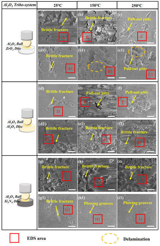
Figure 11.
The SEM results of (a–i) the Al2O3 ceramic ball, (a1–c1) ZrO2 ceramic disc, (d1–f1) Al2O3 ceramic disc, and (g1–i1) Si3N4 ceramic disc under CPSO as a lubricant at 25 °C, 150 °C, and 250 °C; the relative movement direction of the mated interface is horizontal in each picture; all the scale bars are 10 μm.
In the Si3N4 tribo-system, as shown in Figure 12, SEM analysis reveals that the dominant wear mechanisms are fatigue wear and abrasive wear. All the wear surfaces of Si3N4 balls in this system exhibit slight plowing grooves and brittle fractures. Brittle fractures and abundant material pull-out pits were observed on the three ceramic discs, which were associated with fatigue wear and evidence of abundant material pull-out pits. These observations suggest that the Si3N4 system is also the same as the Al2O3 system: the dominant wear mechanism is material fatigue caused by ceramic fatigue cracking and abrasive wear. The EDS spectra corresponding to the marked areas are presented in Table S3.
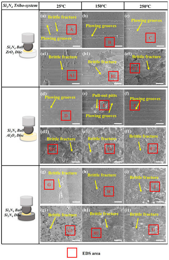
Figure 12.
The SEM results of (a–i) the Si3N4 ceramic ball, (a1–c1) ZrO2 ceramic disc, (d1–f1) Al2O3 ceramic disc, and (g1–i1) Si3N4 ceramic disc under CPSO as a lubricant at 25 °C, 150 °C, and 250 °C; the relative movement direction of the mated interface is horizontal in each picture; all the scale bars are 10 μm.
Among three ceramic materials, slight plowing grooves are more likely observed in the Si3N4 and Al2O3 ceramic system, whereas the adhesive wear caused by ceramic fatigue cracking can be easily found in the ZrO2 tribo-system.
To study the interface composition of the wear scar, XPS measurements were performed. The XPS results of Zr 3d, O 1s, Al 2p, and Si 2p were calibrated using Shirley-type background subtraction. Table 4 shows the XPS results of the Zr 3d, O 1s, Al 2p, and Si 2p of three ceramic discs at 250 °C. The spectral lines at 182.2–183.2 eV correspond to Zr 3d5/2, while the peak at 184.6–185.6 eV relates to Zr 3d3/2. This spectrum of Zr 3d only exists in the tribo-system with ZrO2 materials. The O 1s peaks at 530.2 eV and 532.3 eV can be identified as ZrO2 and oxygen elements in CPSO. The peak of Al 2p appearing at 74.6 eV can be identified as the Al 2p3/2 and Al 2p1/2 of Al2O3. The XPS peaks of Al 2p in Si3N4 discs are due to the Al-containing additive. The peak of Si 2p appearing at 102.2 eV and 102.8 eV belongs to the Si 2p3/2 and Si 2p1/2 O-Si-(CH3)3 of CPSO [16].

Table 4.
Summary of XPS results of Zr 3d, O 1s, Al 2p, and Si 2p of three ceramic discs at 250 °C.
The XPS results show that the presence of CPSO was detected on the surface of the wear scars and no tribological reaction products were generated. The wear mechanism of CPSO in the ceramic tribo-pair is mainly based on ceramic fatigue and abrasive wear.
In order to better understand the mechanism of CPSO in a ceramic tribo-pair from an energetic point of view, the simulation results of CPSO adsorption on the three different ceramic surfaces are presented in Figure 13. Figure 13 illustrates the potential adsorption sites and adsorption configurations of CPSO, where the intensity of coloration represents the intensity of adsorbate adsorption on the respective surfaces. Predominantly, CPSO molecules are adsorbed in proximity to the surface atoms of ceramics, with adsorption sites exhibiting a high degree of concentration.
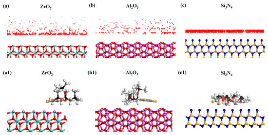
Figure 13.
Potential adsorption sites of CPSO molecular model on different surfaces of (a) ZrO2 (1 1 1), (b) Al2O3 (1 −1 2), (c) Si3N4 (0 0 2), and adsorption configurations of CPSO on different surfaces of (a1) ZrO2 (1 1 1), (b1) Al2O3 (1 −1 2), (c1) Si3N4 (0 0 2). Zr (light blue), O (red), Al (purple), N (dark blue), Si-Si3N4 (light yellow), Si-CPSO (black), C (grey), Cl (light orange), H (white).
The results yielded by the adsorption locator module are pivotal for comparing the interactions among the three ceramic surfaces and CPSO. This module facilitates the determination of energies associated with each ceramic structure formed by the adsorbent (ceramic surfaces) and the adsorbate (CPSO). Specifically, it provides values for total energy, rigid adsorption energy, deformation energy, and adsorption energy [23]. As detailed in Table 5, the computation of adsorption energies for CPSO on various ceramic surfaces reveals that the adsorption energies are negative across ceramic surfaces (ZrO2, Al2O3, Si3N4). Notably, the adsorption energy for CPSO on the Si3N4 ceramic surface recorded the lowest value.

Table 5.
Calculation of adsorption energies.
The adsorption structures of CPSO molecules on various ceramic substrates exhibits significant variability. Specifically, the adsorption configurations of CPSO on ZrO2 and Al2O3 ceramics are similar, characterized by the chlorophenyl structures aligning parallel to the ceramic surfaces. In contrast, a significant distortion in the adsorption structure of CPSO molecules is observed on the Si3N4 ceramic substrate. This differential adsorption behavior is further supported by the calculated adsorption energies, indicating the adsorption energy for CPSO on Si3N4 is almost 54.09 and 61.18 times higher compared to that for ZrO2 and Al2O3 ceramics. The molecular configuration of CPSO on Si3N4 undergoes a more severe distortion due to the greater adsorption energy. Consequently, the superior adsorption performance of CPSO on Si3N4 ceramics leads to the superior tribological performance of Si3N4/Si3N4/CPSO.
The HOMO and LUMO energies (EHOMO, ELUMO) of a molecule indicate its electron-donation and electron-acceptance capabilities, respectively. The energy gap ΔE can be calculated through ELUMO-EHOMO. A smaller ΔE suggests a lower energy requirement to remove an electron from the HOMO, leading to enhanced adsorption capacity and molecular activity [24]. As shown in Table 6, the ΔE of CPSO (Si3N4) is the smallest among the CPSO molecules of the three ceramic surfaces, with only 1.84% and 1.88% of the ΔE of CPSO (ZrO2) and CPSO (Al2O3), indicating that the CPSO (Si3N4) has much higher molecular activity than the other two adsorbed molecules.

Table 6.
Energy gap of adsorbed CPSO molecule of three ceramic surfaces.
The wetting effects of CPSO on various ceramic surfaces were verified through contact angle measurements (OCA25, Dataphysics, Germany). In the droplet-spreading process, 4 μL droplets were released from a height of 18 cm onto the ceramic surfaces. A high-speed camera with a sampling frequency of 1000 Hz and a resolution of 800 × 600 pixels was used to capture images of the droplets, starting 1 s after impact. Then, the contact angle of CPSO on each ceramic surface was calculated by software.
The results of the contact angle of CPSO on different ceramic surfaces are shown in Figure S4. The average contact angle of CPSO on the three ceramic surfaces can be ordered by ZrO2 (12.3°) > Al2O3 (12.2°) > Si3N4 (11.1°). It can be observed that the contact angles of ZrO2 and Al2O3 are similar, while the contact angle of silicon nitride ceramics is significantly smaller. This indicates that CPSO exhibits better wettability on the surface of silicon nitride ceramics, and the CPSO molecules spread more thoroughly on the silicon nitride surface. This observation is consistent with the results of adsorption simulations.
Above all, the friction process of CPSO in a ceramic tribo-pair begins with the adsorption of lubricant molecules on the surface of the ceramic material. The coefficient of friction and wear rate are related to the surface adsorption energy; the coefficient of friction of Si3N4, which has the largest adsorption energy, is more stable, which is due to the fact that the lubricant molecules can better adsorb on the surface of the friction pair and form an effective boundary lubrication film; on the contrary, on the ZrO2 and Al2O3 ceramic surfaces, the adsorption energy of CPSO is low and the wear rate is relatively high. From the SEM results of the wear scars, it can be obtained that the main forms of wear of the ceramic tribo-pairs are ceramic fatigue wear and the resulting abrasive wear and adhesive wear, in which the ZrO2 system is dominated by fatigue wear and adhesive wear, while Al2O3 and Si3N4 are dominated by fatigue wear and abrasive wear.
In summary, CPSO molecules effectively adsorb onto three distinct types of ceramic surfaces. During the sliding process, the adsorption film formed on these surfaces is continuously disrupted and regenerated. This dynamic process of adsorption and disruption can result in contact with the asperities of rubbing materials, potentially impacting the stability of the COF. Notably, on Si3N4 ceramic surfaces, the strong adsorption energy of CPSO, coupled with its lower energy gap, allows the adsorption film to adhere more stably to the ceramic material’s surface. This stable adsorption layer effectively isolates the moving surfaces, preventing further wear and maintaining a lower COF, thereby enhancing the lubrication performance.
5. Conclusions
In this study, a high-temperature ceramic tribo-pair system utilizing chlorophenyl silicone oil (CPSO) as a lubricant was developed. The lubrication performance and mechanism were studied in this work.
(1) Among the three ceramic tribological pair systems, the lubrication performance of CPSO can be ordered as Si3N4 > Al2O3 > ZrO2, as the wear rates of the ZrO2 and Al2O3 tribo-systems are almost 1135.67 and 283.33 times larger than that of Si3N4 the tribo-system, respectively.
(2) The primary wear mechanisms of the ZrO2 ceramic tribo-system are adhesive wear and the dominant wear mechanisms. However, the primary wear mechanisms of the Al2O3 and Si3N4 ceramic tribo-systems are abrasive wear and fatigue cracking.
(3) The molecular dynamic simulation results reveal the superior tribological performance of Si3N4/Si3N4/CPSO. The calculated adsorption energy of CPSO/Si3N4 is almost 54.09 and 61.18 times higher compared to that on ZrO2 and Al2O3 ceramics. Therefore, the formed boundary film of the Si3N4 ceramic surface is very stable. These insights provide substantial empirical data and a theoretical framework for understanding the lubrication performance of CPSO in ceramic tribo-systems.
Supplementary Materials
The following supporting information can be downloaded at: https://www.mdpi.com/article/10.3390/lubricants12070249/s1, Figure S1: Depth profile of wear scar size of (a) ZrO2 ceramic disc, (c) Al2O3 ceramic disc, and (e) Si3N4 ceramic disc; (b,d,f) depth profile of wear scar diameter of ZrO2 ball under CPSO as lubricant at 25 °C, 150 °C, and 250 °C; Figure S2: Depth profile of wear scar size of (a) ZrO2 ceramic disc, (c) Al2O3 ceramic disc, and (e) Si3N4 ceramic disc; (b,d,f) depth profile of wear scar diameter of Al2O3 ball under CPSO as lubricant at 25 °C, 150 °C, and 250 °C; Figure S3: Depth profile of wear scar size of (a) ZrO2 ceramic disc, (c) Al2O3 ceramic disc, and (e) Si3N4 ceramic disc; (b,d,f) depth profile of wear scar diameter of Si3N4 ball under CPSO as lubricant at 25 °C, 150 °C, and 250 °C; Table S1: EDS results of marked area in Figure 10; Table S2: EDS results of marked area in Figure 11; Table S3: EDS results of marked area in Figure 12; Figure S4: The contact angle of CPSO on different ceramic surfaces: (a1–a3) ZrO2; (b1–b3) Al2O3; (c1–c3) Si3N4.
Author Contributions
Writing—original draft preparation, J.C.; software, Y.M. (Yan Meng); writing—review and editing, P.B. and Y.T.; investigation, F.S., L.Y., X.Z., P.W., H.Z. and X.W.; supervision Y.M. (Yonggang Meng), Q.Z. and Y.T.; project administration, P.B. All authors have read and agreed to the published version of the manuscript.
Funding
This work was supported by the National Natural Science Foundation of China (No. 52275198, 52075037), Beijing Natural Science Foundation (3222017), Tribology Science Fund of State Key Laboratory of Tribology (No. SKLTKF21A01), The Postdoctoral Fellowship Program of CPSF (No. GZC20231287), The National Defense Science and Technology Key Laboratory Foundation of China (No. 614221722020401), Central Universities outstanding youth team project of CUMTB (2023YQTD03), and Fundamental Research Funds for the Central Universities (2024ZKPYJD091).
Data Availability Statement
The original contributions presented in the study are included in the article; further inquiries can be directed to the corresponding author.
Conflicts of Interest
The authors declare no conflicts of interest.
References
- El Laithy, M.; Wang, L.; Harvey, T.J.; Vierneusel, B.; Correns, M.; Blass, T. Further understanding of rolling contact fatigue in rolling element bearings—A review. Tribol. Int. 2019, 140, 105849. [Google Scholar] [CrossRef]
- Bai, X.; Shi, H.; Zhang, K.; Zhang, X.; Wu, Y. Effect of the fit clearance between ceramic outer ring and steel pedestal on the sound radiation of full ceramic ball bearing system. J. Sound Vib. 2022, 529, 116967. [Google Scholar] [CrossRef]
- Mazumder, S.; Metselaar, H.S.C.; Sukiman, N.L.; Mohd Zulkifli, N.W. Friction and wear behavior of fluoride added Si3N4-SiC ceramic composites at elevated temperature. Ceram. Int. 2023, 49, 12787–12795. [Google Scholar] [CrossRef]
- Radhika, N.; Sathish, M. A review on si-based ceramic matrix composites and their infiltration based techniques. Silicon 2022, 14, 10141–10171. [Google Scholar] [CrossRef]
- Malinverni, C.; Salvo, M.; De Zanet, A.; D’Isanto, F.; Smeacetto, F.; Bertrand, P.; Puchas, G.; Schafföner, S.; Casalegno, V. Glass-ceramics for joining oxide-based ceramic matrix composites (Al2O3f/Al2O3-ZrO2) operating under direct flame exposure. J. Eur. Ceram. Soc. 2023, 43, 3621–3629. [Google Scholar] [CrossRef]
- Sun, J.; Wu, Y.; Yang, J.; Yao, J.; Xia, Z. Friction properties and distribution rule of lubricant film of full ceramic ball bearing under different service condition. Ceram.-Silik. 2022, 66, 54–65. [Google Scholar] [CrossRef]
- Tian, J.; Wu, Y.; Sun, J.; Xia, Z.; Ren, K.; Wang, H.; Li, S.; Yao, J. Thermal dynamic exploration of full-ceramic ball bearings under the self-lubrication condition. Lubricants 2022, 10, 213. [Google Scholar] [CrossRef]
- Yao, J.; Wu, Y.; Yang, J.; Sun, J.; Xia, Z.; Tian, J.; Bao, Z.; Gao, L. Study on distribution of lubricating oil film in contact micro-zone of full ceramic ball bearings and the influence mechanism on service performance. Lubricants 2022, 10, 174. [Google Scholar] [CrossRef]
- Yuan, J.; Tong, Y.; Wang, J.; Lv, B.; Ma, L.; Wang, D. Effect of lubricant viscosity on the performance and damage of high speed ball bearing. J. Harbin Inst. Technol. 2021, 53, 94–100. [Google Scholar]
- Yan, S.; Lin, B.; Zhang, X. State-of-the-art and key technologies of water lubricated ceramic spindle. J. Hebei Univ. Sci. Technol. 2018, 39, 477–486. [Google Scholar]
- Han, F.; Wen, H.; Sun, J.; Wang, W.; Fan, Y.; Jia, J.; Chen, W.J.M. Tribological properties of Si3N4-hBN composite ceramics bearing on GCr15 under seawater lubrication. Ind. Lubr. Tribol. 2020, 13, 635. [Google Scholar] [CrossRef] [PubMed]
- Sun, J.; Fang, X.; Yao, J.; Zhang, Z.; Guan, R.; Zhang, G. Thermal characteristics and distribution rule of lubrication film of full ceramic ball bearing under different service condition. Ind. Lubr. Tribol. 2023, 75. [Google Scholar] [CrossRef]
- Lin, G.; Wang, S.; Wang, L. Tribology performance and leakage of ball bearing lubricated by chlorphenyl silicone oil in vacuum. Tribology 2009, 29, 526–530. [Google Scholar]
- Weng, L.; Wang, H.; Feng, D.; Pan, G.; Duan, Y.; Liu, W.; Xue, Q. Synthesis and tribological behavior of a chlorinated-phenyl methyl-terminated silicon oil as aerospace lubricant. Tribology 2005, 25, 254–257. [Google Scholar]
- Schiefer, H.M.; Awe, R.W.; Whipple, C.L. Extending the utility of silicone lubricants through structural modifications. J. Chem. Eng. Data 1961, 6, 155–160. [Google Scholar] [CrossRef]
- Schiefer, H.M.; John, V.D. Boundary lubricating properties of fluoroalkyl silicones in bench and pump tests. ASLE Trans. 1964, 7, 32–42. [Google Scholar] [CrossRef]
- Weng, L.; Wang, H.; Feng, D.; Liu, W.; Xue, Q. Tribological behavior of the synthetic chlorine- and fluorine-containing silicon oil as aerospace lubricant. Ind. Lubr. Tribol. 2008, 60, 216–221. [Google Scholar] [CrossRef]
- Jiang, K.; Zhang, X. Lubricity of fluorosilicone. J. Aeronaut. Mater. 2011, 31, 81–85. [Google Scholar] [CrossRef]
- Wen, X.; Bai, P.; Meng, Y.; Ma, L.; Tian, Y. High-temperature superlubricity realized with chlorinated-phenyl and methyl-terminated silicone oil and hydrogen-ion running-in. Langmuir 2022, 38, 10043–10051. [Google Scholar] [CrossRef]
- Lonje, B.M.; Liu, G. Investigation of adsorption behaviors of paraffin waxes on iron, iron ii oxide, and iron iii oxide surfaces using the adsorption locator model. Arab. J. Sci. Eng. 2022, 47, 11763–11773. [Google Scholar] [CrossRef]
- Fahimirad, B.; Malekshah, R.E.; Chamjangali, M.A.; Abasabadi, R.K.; Bromand, S. Theoretical and experimental study of the photodegradation of methyl orange in the presence of different morphologies of Au-ZnO using Monte Carlo dynamic simulation. Environ. Sci. Pollut. Res. 2022, 29, 55131–55146. [Google Scholar] [CrossRef] [PubMed]
- Menezes, P.; Ingole, S.; Nosonovsky, M.; Kailas, S.; Lovell, M. Tribology for Scientists and Engineers; Springer: New York, NY, USA, 2013. [Google Scholar] [CrossRef]
- García, E.V.; Carbajal-Franco, G.; López-Galán, O.A. DFT transition state study of the catalyzed oxidation of methane on SnO2 surfaces. Catal. Today 2022, 392–393, 41–48. [Google Scholar] [CrossRef]
- Pelalak, R.; Soltani, R.; Heidari, Z.; Malekshah, R.E.; Aallaei, M.; Marjani, A.; Rezakazemi, M.; Kurniawan, T.A.; Shirazian, S. Molecular dynamics simulation of novel diamino-functionalized hollow mesosilica spheres for adsorption of dyes from synthetic wastewater. J. Mol. Liq. 2021, 322, 114812. [Google Scholar] [CrossRef]
Disclaimer/Publisher’s Note: The statements, opinions and data contained in all publications are solely those of the individual author(s) and contributor(s) and not of MDPI and/or the editor(s). MDPI and/or the editor(s) disclaim responsibility for any injury to people or property resulting from any ideas, methods, instructions or products referred to in the content. |
© 2024 by the authors. Licensee MDPI, Basel, Switzerland. This article is an open access article distributed under the terms and conditions of the Creative Commons Attribution (CC BY) license (https://creativecommons.org/licenses/by/4.0/).