1. Introduction
Gears are essential industrial components, and due to their often harsh operating conditions, various gear failures occur frequently during the working process [
1]. Contact fatigue is the most common among the various failure forms of gears [
2]. Surface hardness, surface roughness, and maximum compressive residual stress are key factors that affect the contact fatigue life and fatigue limit of gears [
3]. Proper heat treatment of gears can enhance their surface hardness, improve their residual stress state, and thus enhance their fatigue life [
4,
5]. The diffusion-strengthening technology represented by carburization, nitriding, and nitrocarburization can significantly improve the surface hardness, fatigue strength, and wear resistance of materials and has been widely applied in engineering [
6,
7,
8,
9,
10,
11].
Nitriding is one of the traditional heat treatment processes, which has the characteristics of small deformation, low temperature, simple process and low cost. Compared with carburizing, nitriding can make the steel surface obtain higher surface hardness, wear resistance, fatigue strength and corrosion resistance. M. Gomann [
8] proved that ion beam nitriding technology significantly enhances the bearing capacity of gears, yielding a 1.31-fold increase compared to traditional nitrided gears. Furthermore, the wear resistance of these ion beam nitrided gears is found to be twice as high as that of gears treated with conventional heat treatment methods. P. Cĕlko’s study [
9] involved the treatment of 50CrV4 low alloy steel with ion nitride at 500 °C for 20 h. This process resulted in the formation of a 3.72 μm thick compound layer consisting of ε-Fe2-3N and γ’-Fe4N nitrides, along with a 212 μm thick diffusion layer. Notably, this treatment led to a 57% increase in fatigue resistance. Zhang et al. [
6,
7,
8] designed a hollow cathode-assisted device to improve ion density during diffusion. At the same time, simulation analysis was conducted on the distribution of ion during the ion nitriding process based on hollow cathode assisted, and experimental verification was conducted. The results showed that ion nitriding based on a hollow ion source can significantly improve the surface properties of various materials such as stainless steel and titanium alloy. Li [
5,
9] used hollow cathode ion nitriding technology to treat alloy structural steel, and the results showed that ion nitriding can significantly improve the comprehensive performance of alloy structural steel.
However, due to the thin nitriding layer of ordinary nitriding process, its impact resistance and bearing capacity are not enough to meet the needs of heavy-duty gear [
12,
13]. The single treatment method can not meet the performance requirements of high fatigue strength, high bending strength, high hardness, low friction and wear, and high speed and heavy load [
10,
11]. Carburizing is a common strengthening technology for gears, and it can make gears obtain good comprehensive performance, the combination of gas carburizing and ion nitrocarburizing is a good composite treatment method. Nonetheless, it is still necessary to consider whether the treatment temperature of ion nitrocarburizing will cause deterioration of the sample after carburizing and quenching. Although research on carbonitriding or ion carbonitriding has been very systematic and in-depth, there is still relatively little research on the composite treatment process of gas carburization and ion carbonitriding. Especially in existing research, the temperature of ion carbonitriding is generally higher than 500 °C, but there is a slight involvement in low-temperature ion carbonitriding with a diffusion temperature of 400 °C [
12,
13,
14,
15,
16].
The gear steel, by carburization and quenching treatment, resulted in a significant increase in surface carbon content, forming a microstructure mainly composed of martensite matrix and residual austenite [
17,
18,
19,
20,
21]. It has a high surface hardness, and the residual stress after quenching can be eliminated through tempering. The more typical range of tempering temperature is 150–250 °C. The changes in microstructure and element distribution during the carburizing and quenching process determine the microhardness and hardness gradient of the carburized layer, affecting gears’ friction and wear performance [
22,
23]. The different tempering temperatures may lead to microstructure changes such as residual austenite transformation, cementite precipitation, and martensite transformation. In addition, the differences in alloy elements can also have a particular impact on microstructure transformation [
24,
25,
26,
27,
28,
29].
This study aimed to optimize the gas carburizing temperature and low-temperature ion nitrocarburizing temperature to achieve an effective combination of the two processes. The objective was to maintain the carburizing hardness of the samples while simultaneously enhancing the surface hardness and wear resistance.
2. Materials and Methods
The 18Cr2Ni4WA sample is made of 80 mm diameter round rods. The sample is a disc with a diameter of 24 mm and a thickness of 8 mm. Then, it is carburized at 920 °C for 3.5 h and cooled to room temperature. After two high-temperature tempering cycles, it is oil-quenched. Finally, it is stress-relieved and annealed at different temperatures. A schematic of the heat-treating process for 18Cr2Ni4WA steel is shown in
Figure 1, and the samples are treated at different tempering and ion nitrocarburizing temperatures.
Table 1 shows the chemical composition of the sample.
The surface hardness of the sample and the hardness gradient of the carburized layer were measured using a digital microhardness tester (QNESS Q60+, ATM Qness GmbH, Mammelzen, Germany). Scanning electron microscopy (SEM, Quanta 200 FEG, FEI, Hillsboro, NC, USA) is used to observe the microstructure of the sample surface. The chemical element composition at the surface diffusion layer before and after ion carbonitriding was analyzed by energy dispersive X-ray spectroscopy (EDS), and the diffusion effect was analyzed from the changes in the content of C and N elements. Generally speaking, an increase in the content of N and C elements in the surface layer is beneficial for surface hardness. The high temperature tribotester (Optimal SRV-4, Optimol Instruments, Munich, Germany) was used to perform friction tests at 6 N and 60 N, respectively. The upper sample used in the tests is a GCr15 steel ball with a diameter of 10 mm, and the lower sample is a circular sample with a diameter of 24 mm. All lower samples have undergone the same polishing treatment and have the same surface roughness. The testing time for each experiment is 30 min, with a linear reciprocating motion and a frequency of 2 Hz. The lubricating oil is Mobil 85W-140 heavy-load gear oil. The optical microscope (OM, Axio Observer 3 materials, ZEISS, Oberkochen, Germany) was used to observe the metallographic structure of the sample section. The morphology of the wear marks on the surface of the sample was analyzed with a three-dimensional white light interference topography instrument (NeXView, ZYGO, Middlefield, CT, USA).
The gas carburization process was conducted utilizing sealed box type carburizing and quenching multi-purpose furnace (BQC-1000, Jsecoo, Yancheng, China). Following a 3.5 h carburization period, the samples were additionally tempered twice at a high temperature for 3 h. Strong carburizing potential is 1.15%, diffusion carbon potential is 0.8%. The protective gas of high temperature tempering is nitrogen, and the sample is cooled with the furnace. When the temperature in the furnace is below 200 °C, the sample is taken out and cooled in the air. The protective gas of high temperature tempering is nitrogen, and the sample is cooled with the furnace. When the temperature in the furnace is below 200 °C, the sample is taken out and cooled in the air. Two high temperature tempering can eliminate most of the residual austenite. Subsequently, they were quenched for 3.5 h before being tempered at different temperatures. Natural gas and CH4 gas are introduced into the quenching process, and the quenching medium is Y15-II quenching oil of Beijing Huali.
The ion nitrocarburized strengthening device (FD-CMF40/60-30X2, Fengdong, Qingdao, China) adopts an insulated furnace body, and the furnace liner adopts a muffle structure. The heater is arranged outside the furnace liner and equipped with an independent cooling system. The pressure inside the furnace is closed-loop automatically controlled, and a mass flow meter accurately controls the flow rate. Equipped with professional industrial control computers and expert simulation software, it can automatically control the nitriding process. The sample is placed on a cathode tray so that the sample is surrounded by a hollow cathode auxiliary device. Nitrogen, hydrogen and methane are injected to keep the pressure of the furnace at 300 Pa. The samples were treated at three different temperatures for 3 h. The surface of samples used in the paper is sanded and polished with SiC sandpaper from coarse to fine (800# to 2000#) until they become a smooth mirror surface with a surface roughness of less than 0.08 μm.
The samples undergoing different processing treatments were distinguished and recorded in
Table 2.
3. Results and Discussion
To mitigate the impact of tempering temperature on the surface hardness of samples and to enhance the maximum limit of ion nitrocarburized temperature, it is imperative to select an elevated tempering temperature [
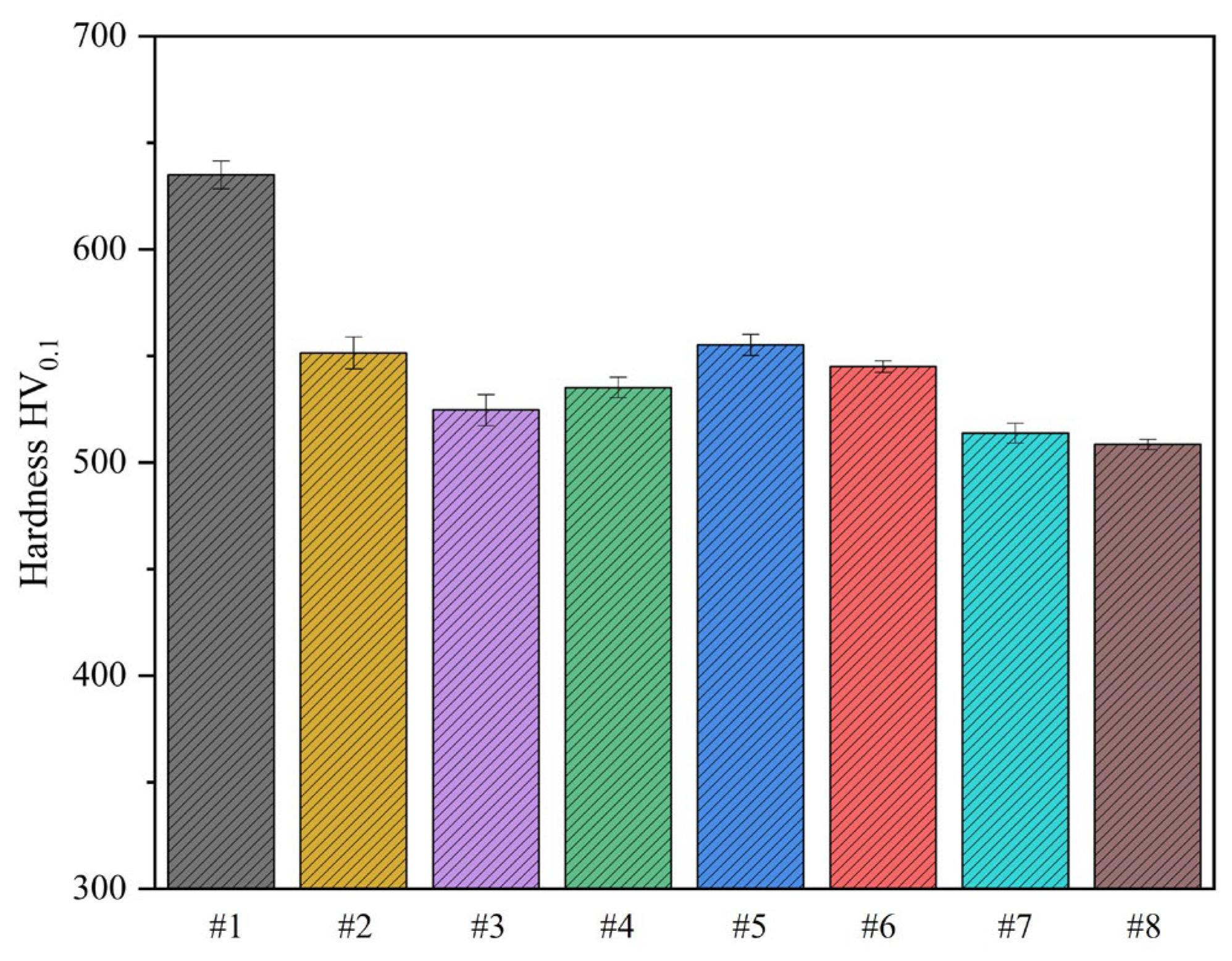
30]. This present study involved an experiment where carburized samples were subjected to tempering treatments at varying temperatures to obtain eight samples with different tempering temperatures. The Vickers hardness of the resulting samples was subsequently determined, as illustrated in
Figure 2. Notably, the maximum Vickers hardness of 635 HV
0.1 was recorded when tempering was performed at 220 °C. However, with an increase in the tempering temperature, the surface hardness of the samples exhibited a decreasing trend, albeit not proportionally. An elevation in the tempering temperature results in the release of a more significant amount of internal residual stress.
Consequently, the overall hardness diminishes [
31,
32]. Surprisingly, a reversal in the decreasing trend of surface hardness was observed with a tempering temperature of 380 °C. Nevertheless, the surface hardness showed a decreasing pattern again at 420 °C. Notably, a peak surface hardness of 555 HV
0.1 was observed at a tempering temperature of 400 °C. By comparing the Vickers hardness of all eight samples treated at varying temperatures, the optimal tempering temperature was between 400 °C and 420 °C. The sample material 18Cr2Ni4WA contains a large amount of Cr and W elements, both of which are strong carbide forming elements. At this temperature range, stable alloy carbides precipitated and underwent diffusion strengthening effect, which we believe may be the reason for the improvement of mechanical properties to a certain extent.
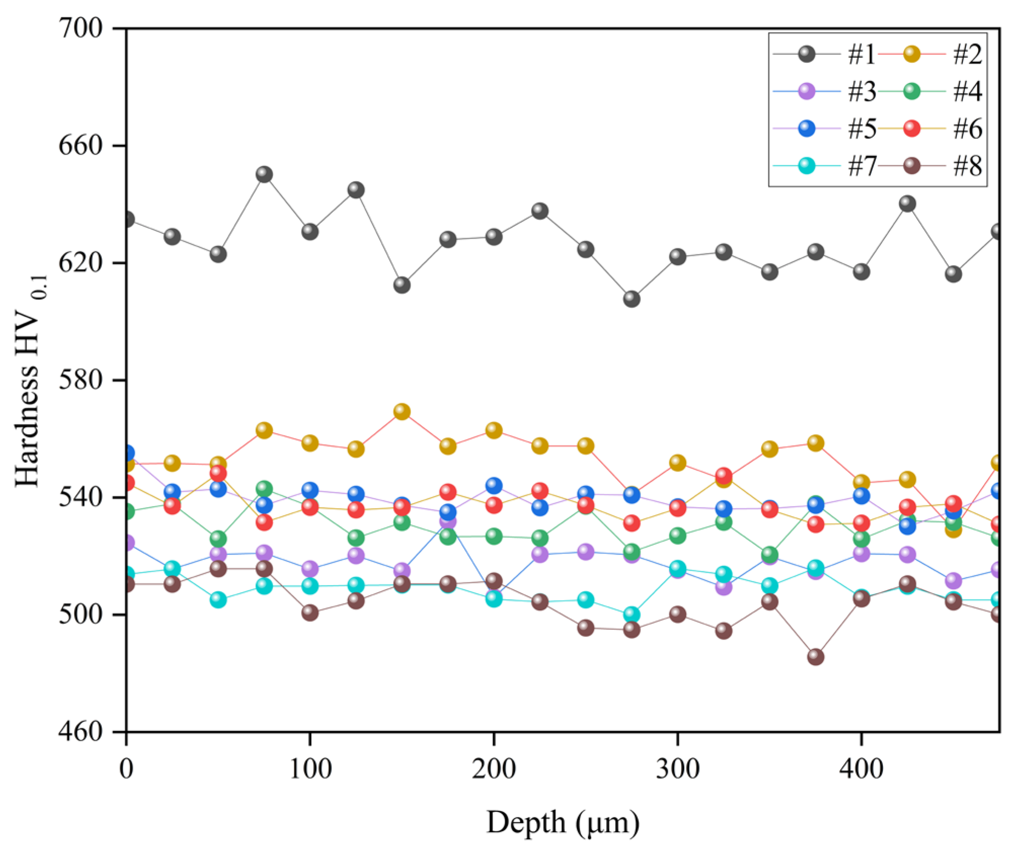
After the Vickers hardness testing of the samples at different tempering temperatures, a cross-sectional hardness gradient test was carried out on the identical specimens, as presented in
Figure 3. It is discernible that the sample tempered at 180 °C exhibited the most optimal hardness gradient distribution. Conversely, a decrease in the hardness gradient of the samples was observed, albeit to varying extents, as the tempering temperature was increased. As the tempering temperature increases, the reduction in the activity of martensite during the cooling process contributes to a decrease in the content of high-carbon martensite. This is accompanied by a reduction in dislocation density and an increase in martensite block width, ultimately reducing overall hardness [
33,
34].
Moreover, the hardness gradient trend was concordant with surface hardness. Interestingly, the samples treated at tempering temperatures of 400 °C and 420 °C showed an ascending trend in the hardness gradient. Notably, the hardness gradient plot for samples #5 and #6 showed minimal fluctuations, indicating uniform hardness distribution prevalent in the samples with values around 540 HV0.1. Consequently, it is concluded that the optimal tempering temperatures for ion nitrocarburizing of 18Cr2Ni4WA steel lie between 400 °C and 420 °C.
The SEM micrographs in
Figure 4 depict the cross-sectional view of samples subjected to different tempering temperatures at 100 μm beneath the surface. A careful examination of the micrographs reveals that an increase in tempering temperature resulted in the coarsening of the grains; however, the sample structure remained unchanged, retaining the martensitic structure in all the tested specimens. Furthermore, the observed decline in hardness is primarily attributed to the coarsening of the grains.
To further investigate the effect of ion nitrocarburizing at different temperatures, samples #5 and #6 were subjected to ion nitrocarburizing treatments at 400 °C and 420 °C, respectively. The surface hardness of these treated samples was then assessed, and the results are presented in
Figure 5. It was observed that ion nitrocarburizing significantly enhanced the surface hardness of the samples, with all samples exhibiting hardness values exceeding 900 HV
0.1. During the process of ion nitrocarburizing, active nitrogen and carbon atoms effectively permeate the sample’s surface, thereby penetrating the underlying substrate. Nitrogen reacts with other elements in the matrix to form compounds. The resultant nitrocarburizing layer significantly enhances the hardness of the sample [
35,
36]. Lattice distortion and residual stress also increase hardness values [
37,
38,
39]. Specifically, sample #5-1 achieved the highest surface hardness of 926 HV
0.1, corresponding to a diffusion temperature of 400 °C, which is the same as its tempering temperature. The ion nitrocarburizing process parameters of sample #6-1 are completely the same as sample #5-1, but the surface hardness of sample #6-1 is lower than that of sample #5-1. The only difference between sample #6-1 and sample #5-1 is that their diffusion temperature is 420 °C, which exceeds the tempering temperature of 400 °C. These findings demonstrate the influence of tempering temperature on ion nitrocarburizing.
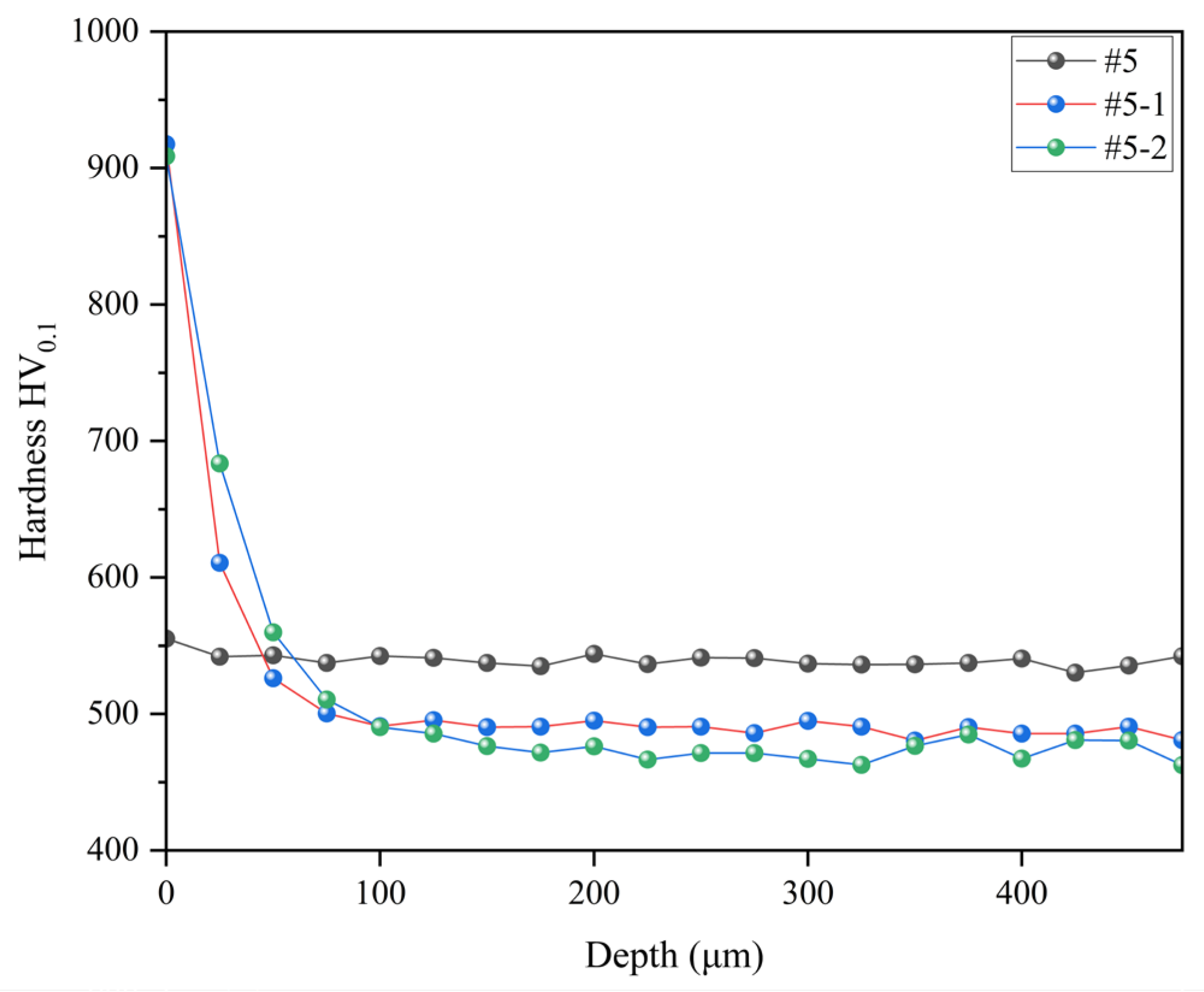
A cross-section hardness gradient test was conducted on samples #5, #5-1 and #5-2 to evaluate the hardness distribution within the samples further. As shown in
Figure 6, the results reveal that the hardness gradient for sample #5 remained relatively stable at around 540 HV
0.1. Upon ion nitrocarburizing treatment, samples #5-1 and #5-2 exhibited a modified layer of approximately 100 μm thickness on the surface, significantly improving hardness. However, compared to the sample subjected only to tempering at 360 °C, the hardness of the samples after ion nitrocarburizing treatment began to decrease at a depth of approximately 50 μm from the surface. The introduction of nitrides can indeed substantially enhance the hardness of the sample. However, it is essential to note that the diffusion capacity of nitrogen diminishes as the diffusion depth increases, leading to a gradual reduction in hardness in the vicinity of the surface [
40]. Moreover, sample #5-1 exhibited slightly higher hardness values beyond the depth of 100 μm from the surface than sample #5-2, with a more stabilized hardness gradient curve. These results indicate that ion nitrocarburizing treatment at 360 °C can be suitable for samples tempered at 360 °C.
The hardness gradient curves of samples #6, #6-1, and #6-2 are illustrated in
Figure 7. Sample #6 exhibits an overall hardness gradient of approximately 540 HV
0.1. Following the ion nitrocarburizing treatment, the general hardness gradient of the samples slightly decreased, albeit within a range of less than 30 HV
0.1. Upon comparison, it was observed that the low-temperature ion nitrocarburizing treatment did not significantly negatively affect sample #6. Simultaneously, the surface hardness at a depth of 50 μm from the surface of samples #6-1 and #6-2 was notably improved. It can be attributed to the precipitation of fine carbides in the martensite during the ion nitrocarburizing process and the conversion of some acicular martensite into lath martensite, resulting in a slight reduction in hardness. To achieve an optimal hardness gradient, conducting the ion nitrocarburizing treatment at a temperature equal to or slightly lower than the tempering temperature is recommended.
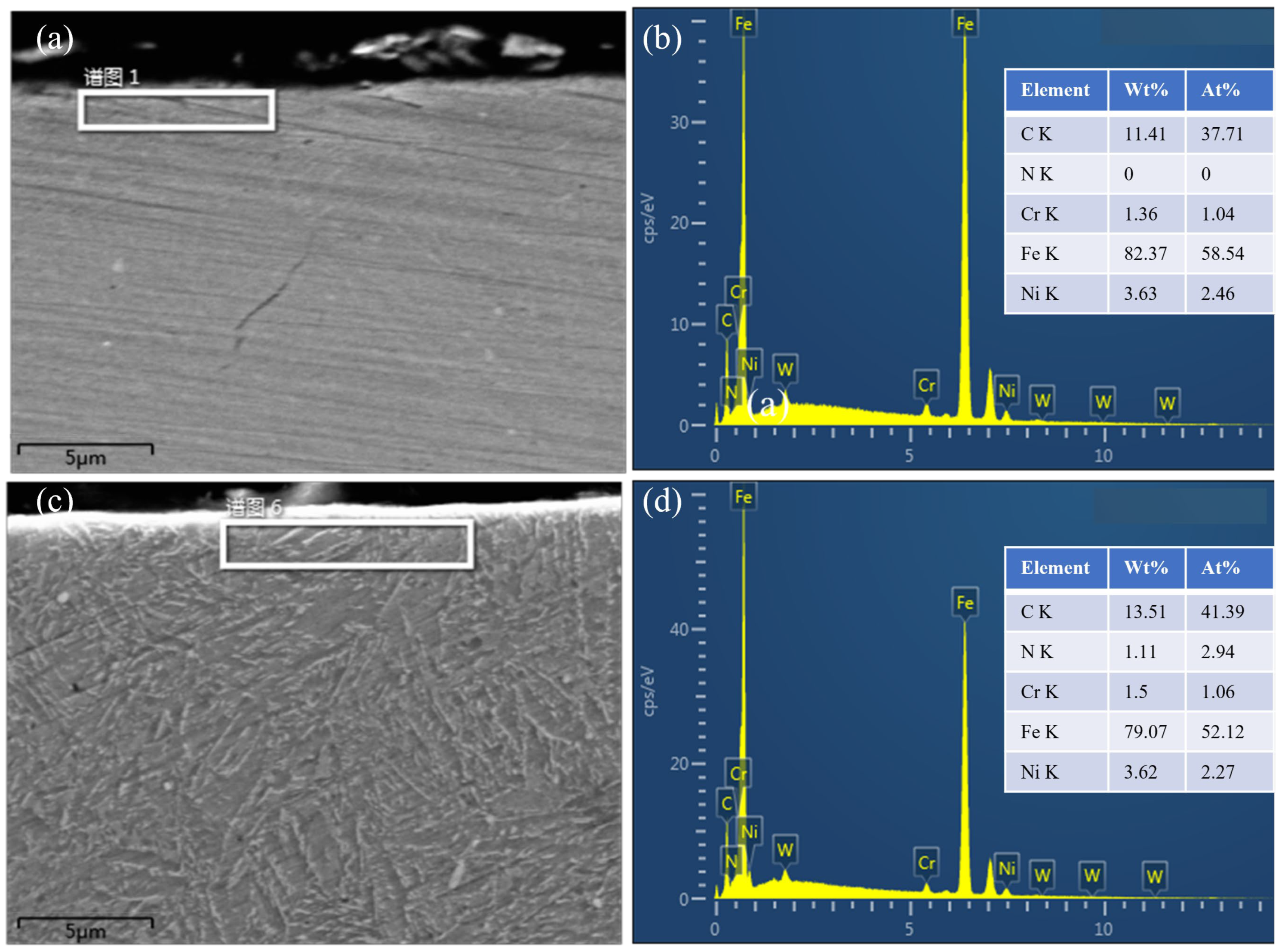
We used EDS to determine the chemical element composition near the surface of samples #6 and #6-2. The tempering temperature of both samples was 420 °C, but the difference was that sample #6-2 underwent 3 h of ion carbonitriding at 420 °C after tempering. The test results are shown in
Figure 8. Compared with
Figure 8b, the content of C and N elements in
Figure 8d has significantly increased, and the proportion of N atoms exceeds that of Ni, which is three times that of Cr. This also reveals to some extent the reason why ion carbonitriding significantly improves the surface hardness of carburized samples.
A reciprocating friction experiment was performed with a low load of 6 N to evaluate the tribological properties of the samples subjected to different ion nitrocarburizing processes. The corresponding results are depicted in
Figure 9. Sample 6 exhibited the lowest coefficient of friction, approximately 0.185, followed by sample 5 at about 0.19. The friction coefficients of the samples increased to varying degrees after undergoing ion nitrocarburizing. Among these samples, 6-2 displayed the lowest coefficient of friction at approximately 0.206, whereas 6-1 and 5-2 exhibited the highest coefficient of friction at about 0.224.
The comparatively low friction coefficient of samples #5 and #6 can be attributed to their ground and polished surfaces, which possess soft cover roughness. The increased friction coefficient in the ion nitrocarburizing samples can be attributed to nitrogen diffusion in the matrix, leading to lattice distortion and an increase in surface roughness [
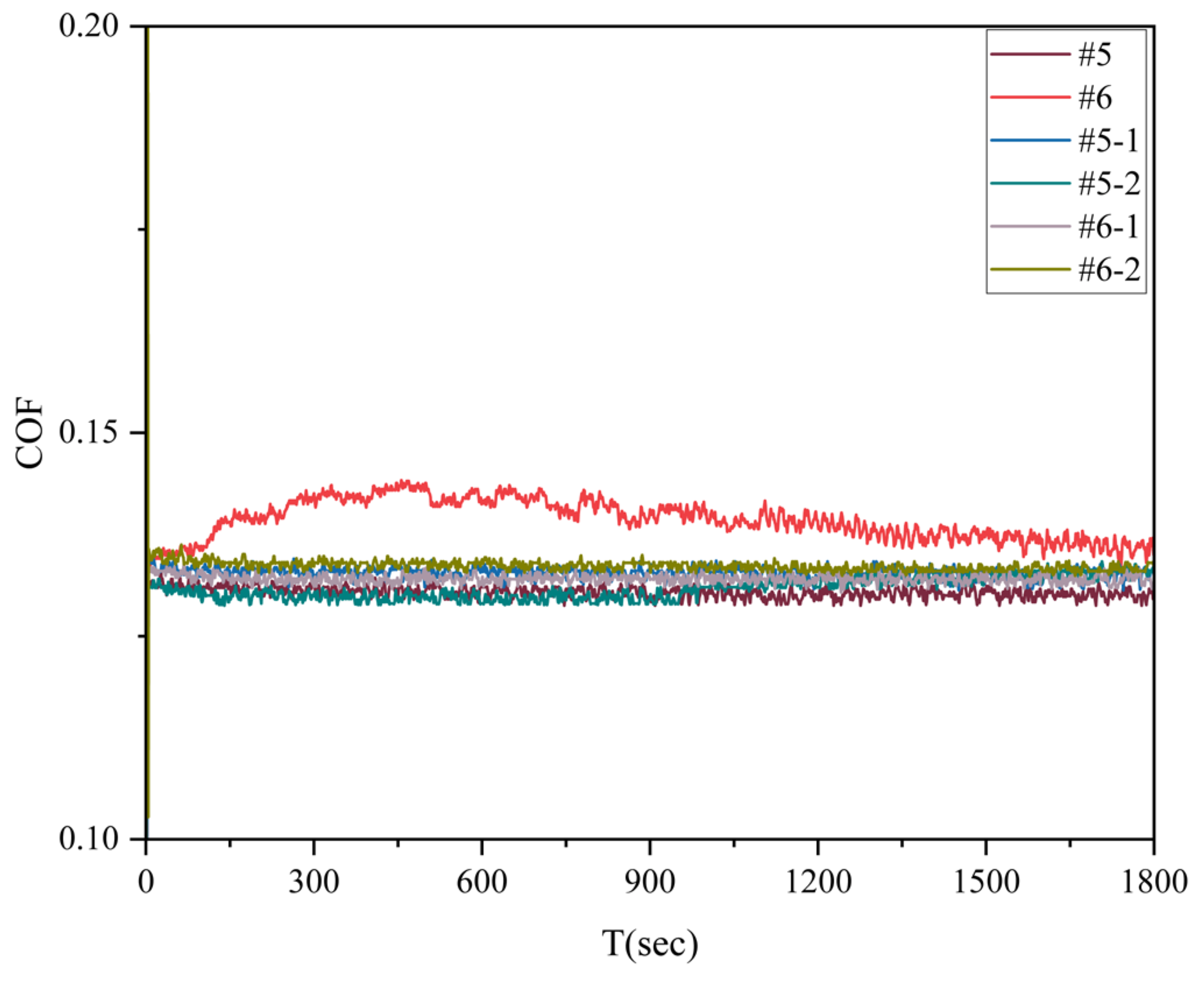
38]. Additionally, a reciprocating friction experiment was conducted under high load conditions of 60 N on the six samples to examine their tribological properties and the corresponding results are presented in
Figure 10. Sample #6 exhibited the highest friction coefficient, approximately 0.137, with significant fluctuations. Conversely, sample #5 displayed the lowest friction coefficient, with a stable curve and no noticeable changes, measuring about 0.125. The friction coefficients of the samples increased to varying degrees after undergoing ion nitrocarburizing but showed similar trends. In the ion nitriding treatment, the surface is constantly exposed to ion bombardment, increasing the number of slip bands. As a result, surface roughness and friction coefficient increase [
41].
To conduct an in-depth analysis of the tribological properties of the samples treated by different ion nitrocarburizing processes under low load, the surface wear of the six samples was examined using a three-dimensional white light interferometer, as shown in
Figure 11. Following the reciprocating friction under a load of 6 N, a distinct deep abrasion mark was evident on the surface of sample #5. Notably, plastic stacking was observed on both sides of the wear marks and furrowed grooves in the middle of the wear marks, indicating plastic deformation and adhesive wear as the predominant friction forms for samples 5 and 6. Conversely, the surface wear patterns of samples 5-1 and 5-2 differed. No plastic accumulation and arch furrows were observed on the sides of the wear marks. Instead, several longitudinal striated folds were apparent, indicating abrasive wear as the primary form of friction in samples 5-1 and 5-2.
Interestingly, no significant abrasion marks were observed on the surfaces of samples 6-1 and 6-2. While the character of sample 6-1 displayed a concave area resembling abrasion marks, it is likely the result of surface deformation following extrusion. Furthermore, the surface of samples 6-2 remarkably appeared flat. The alteration in the friction form of the sample suggests an improvement in the surface hardness, surpassing that of GCr15, as corroborated by the results in
Figure 5.
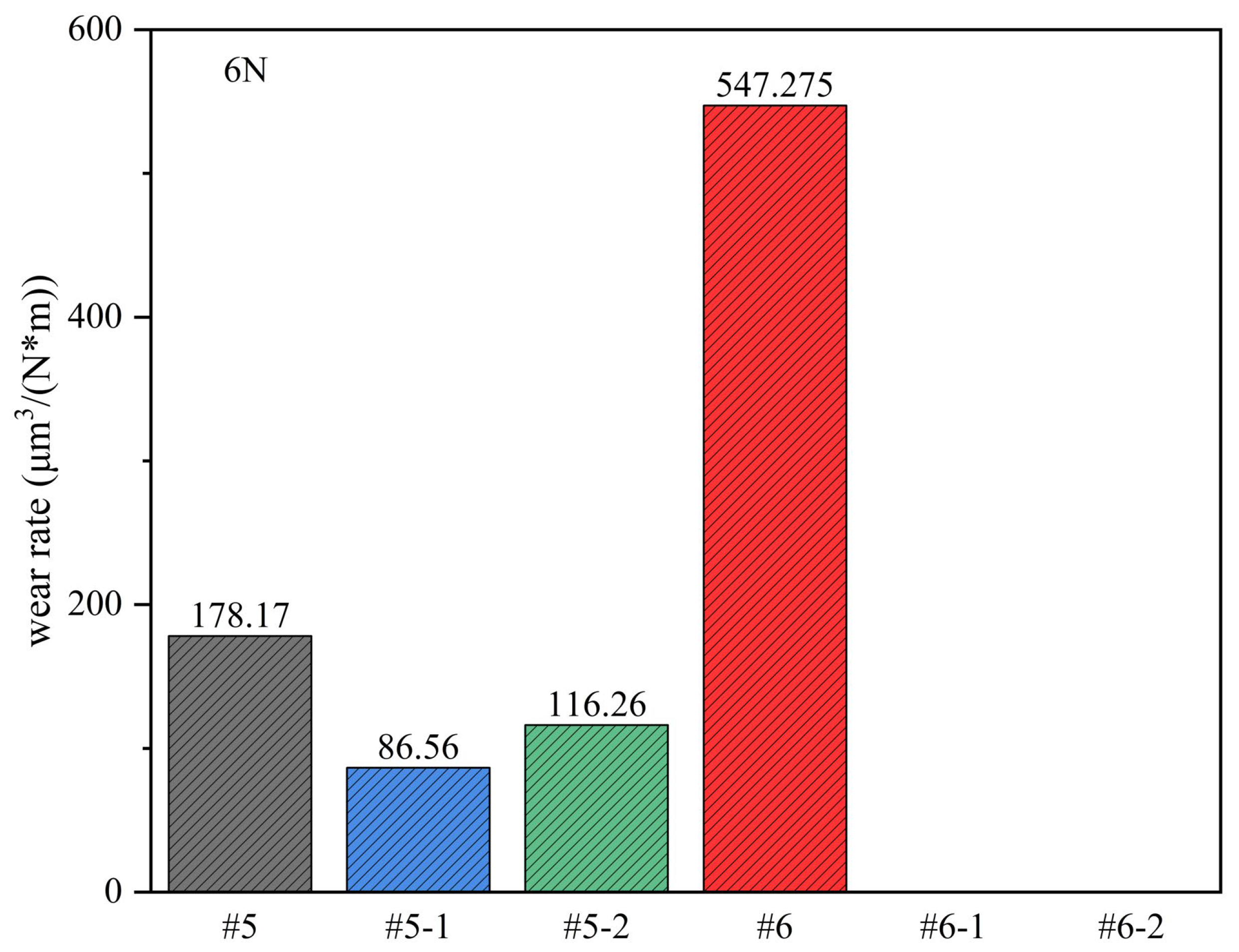
Under a 6 N load, the surface wear amounts for each sample were calculated, as shown in
Figure 12. Sample #6 exhibited the highest wear rate, approximately 547.28 μm
3/(Nm). In comparison, the wear rate of sample #5 was noticeably lower, at around 178.17 μm
3/(Nm). Following the ion nitrocarburizing treatment, a decrease in wear rate was observed for the samples. Specifically, the wear rate of sample 5-1 decreased by 51.4%, and that of sample #5-2 decreased by 34.7%. Similarly, samples #6-1 and #6-2 did not exhibit significant wear, with a zero wear rate. This implies that ion nitrocarburizing can effectively enhance the wear resistance of the samples.
To further analyze the frictional properties of the samples treated by different ion nitrocarburizing processes under high load, a three-dimensional white light interferometer was used to analyze the surface wear of the six samples, as shown in
Figure 13. It was observed that when the load was increased to 60 N, the surface wear marks on the samples became noticeably deeper. Distinct arch-shaped furrows were evident on the surfaces of samples #5 and #6, with varying degrees of plastic stacking on either side of the wear marks. This indicates that the primary friction forms for samples #5 and #6 were plastic deformation and adhesive wear.
Moreover, multiple longitudinal streaked furrows were observed on the surfaces of samples #5-1, #5-2, #6-1, and #6-2, signifying a transformation in the friction forms of the samples post-ion nitrocarburizing treatment to abrasive wear. A comparative analysis showed that the wear marks on samples #5-1 and #5-2 were more profound, with samples #5-2 displaying two intense grooves at the wear mark. In contrast, the surfaces of samples #6-1 and #6-2 exhibited shallow wear marks, akin to their behavior under low load conditions.
Subsequent calculations revealed the surface wear amounts for each sample under the 60 N load, as depicted in
Figure 14. It was observed that sample #6 still exhibited the highest wear rate, at approximately 33,436.84 μm
3/(Nm), while the wear rate for sample #5 was relatively lower, at 2016.96 μm
3/(Nm). Following ion nitrocarburizing treatment, a marked decrease in wear rate was evident for the samples. Sample #5-1 exhibited a wear rate reduction of approximately 68.2%, while sample #5-2 showed a reduction of approximately 36.2%. Notably, the wear resistance of samples #6-1 and #6-2 was significantly improved. Calculations revealed that the wear rate for sample 6-1 decreased by 99.1%, while for sample #6-2, it decreased by an impressive 99.7%. Compared to the untreated sample, the plastic deformation mechanism is reduced due to the hard surface of ion nitriding. This change in wear resistance also depends on the surface roughness and thickness of the nitride layer. The hard ceramic base formed after ion nitriding treatment reduces the severe adhesive wear due to the increased shear resistance [
42,
43]. This underscores the considerable enhancement of wear resistance achieved through ion nitrocarburizing. Conducting ion nitrocarburizing at 420 °C for samples tempered at 420 °C presents a viable industrial production choice.
The hardness of the GCr15 ball as the grinding surface can reach HRC63-65, which is much higher than the surface hardness of the #5 and #6 samples. In the process of friction, the two friction surfaces squeeze each other and move relative to each other, and the soft sample surface will undergo plastic deformation. There are a lot of convex peaks and concave valleys on the micro surface of the sample. When the two friction surfaces come into contact, the convex peak on one side and the concave valley on the other side mesh with each other. When relative movement occurs, the ball with higher hardness will cut the sample surface with lower hardness, resulting in volume loss of the sample surface, and the friction coefficient begins to rise. When the local lubrication suddenly fails, the two contact surfaces will be cold welded, and the surface of the sample with low hardness will be pulled, spalling and adhering to the side with high hardness, and adhesive wear will begin to occur. The surface hardness of the sample was increased after ion nitrocarburizing. During the friction process, the two friction surfaces’ convex peaks and concave valleys will cut each other, and the lost metal will be present in the lubricating oil. Some metal particles will be carried away with the lubricating oil, and some will remain between the two friction surfaces. When relative motion is carried out, the hard metal particles will become abrasive particles, worsening the wear condition, resulting in multiple longitudinal stripes and gullies on the sample surface, and abrasive wear begins to occur.

