Article

Dynamic Modeling of 5-DOF Aerostatic Bearing Rotor System with Adjustable Gas Film Gap

School of Mechanical and Electrical Engineering, Henan University of Science and Technology, Luoyang 471003, China
*
Author to whom correspondence should be addressed.
Lubricants 2024, 12(12), 424; https://doi.org/10.3390/lubricants12120424
Submission received: 21 October 2024 / Revised: 18 November 2024 / Accepted: 25 November 2024 / Published: 30 November 2024

Abstract

:
In the application of an aerostatic motorized spindle, given the different requirements for the optimal gas film thickness of gas bearing under various processing conditions, this paper puts forward the tapered aerostatic bearing as the radial support element of the spindle and realizes the adjustability of gas film gap in a particular range through the axial fine-tuning mechanism. A 5-DOF dynamic model of the bearing rotor system is established, and the transient Reynolds equation is solved using the finite difference method to obtain the pressure distribution characteristics of the gas film. Based on this, the spindle’s translation and angular displacement responses are determined by solving the spindle’s motion equation. The simulation results show that the tilting motion of the spindle significantly affects the pressure distribution of the gas film, and the nonlinear gas film force will lead to nonlinear severe vibration of the spindle. The study also reveals that reducing the gas film thickness under low-speed and heavy-load conditions effectively decreases the amplitude and offset of the spindle. However, increasing the gas film thickness enhances the system’s speed and stability under high-speed and light-load conditions.

1. Introduction

The aerostatic motorized spindle has the advantages of small volume, high rotation speed, small temperature rise, and no pollution, so it is widely used in various ultra-precision and ultra-high-speed equipment [1,2,3,4]. In recent years, with the increasingly stringent requirements for the surface quality and dimensional accuracy of parts in the product manufacturing process, higher requirements have been put forward for the dynamic characteristics of aerostatic motorized spindles, including dynamic stiffness, damping and stability [5,6,7]. Based on the above problems, many scholars have performed a lot of research on the dynamic characteristics of aerostatic motorized spindles. Among them, the commonly used research methods are the dynamic stiffness and damping method, the restoring force and torque method, and the experimental method [8].
The dynamic stiffness and damping method mainly uses the perturbation method to expand the parameters such as gas film pressure, gas film thickness, and mass flow rate by first-order linear Taylor expansion and introduces them into the fluid control equation to obtain the perturbation Reynolds equation, and then solves the perturbation Reynolds equation to obtain the dynamic stiffness and dynamic damping of the bearing. Finally, the displacement curve with time can be obtained by bringing the obtained dynamic coefficient into the spindle motion equation. Li and Liu [9] established a 5-DOF bearing rotor system model and analyzed the dynamic characteristics of the spindle through the dynamic stiffness and damping method. It was concluded that the dynamic response of the spindle was not only influenced by the radial bearing but also by the role of the thrust bearing. Zhao et al. [10] studied the micro-vibration of thrust bearing by using the dynamic stiffness and damping method. They found that disturbance frequency affects dynamic stiffness and damping differently. Specifically, the dynamic stiffness will increase with the increase in disturbance frequency, but the equivalent damping will decrease with the increase in disturbance frequency. Chen et al. [11] studied the micro-vibration of the spindle, solved the dynamic stiffness and dynamic damping coefficient of the radial bearing by the perturbation method, introduced the dynamic coefficient into the motion equation of the spindle, and obtained the displacement error of the spindle in all directions. Lei et al. [12] established a dynamic model of a 5-DOF bearing rotor system under the coupling of multiple physical fields. By solving the dynamic parameters of radial bearings and bringing them into the rotor motion equation, the dynamic characteristics of the rotor in empty cutting and discontinuous cutting were simulated. The results show that the eccentricity of rotor mass and periodic cutting force greatly influence spindle vibration. Shi et al. [13] established a time-varying dynamic model of a multi-degree-of-freedom gas bearing spindle, quantitatively analyzed the influence of force and frequency on the dynamic coefficient of gas bearing and tool deflection by the perturbation method, and gave the corresponding experimental results.
The restoring force and torque method is another commonly used method to study the dynamic characteristics of the aerostatic motorized spindle. This method deduces the motion equation of the spindle through the detailed force analysis of the system, thus solving the translation displacement and angular displacement curves of the spindle and then analyzing its dynamic characteristics. Compared with the dynamic stiffness and damping method, the restoring force and torque method can be used to solve the large amplitude motion of the spindle and can reflect the dynamic motion trajectory of the spindle more intuitively. It can also be used to study the radial and axial runout and critical speed of the spindle. Based on the advantages of the restoring force and torque method, it has often been used to study the 2-DOF motion of the spindle in the previous literature. Zhang et al. [14] established a dynamic model of a 2-DOF bearing rotor system, solved the transient Reynolds equation by the alternating direction implicit method, and studied the nonlinear dynamic characteristics of the rotor by the forecasting orbit method. Wu et al. [15] studied the rotor system with porous tilting pad bearings and studied the effects of gas supply pressure, gas film gap, and radial and tilting stiffness of bearing pads on the nonlinear dynamic characteristics of the system. In recent years, more and more scholars have begun to consider the influence of spindle tilting motion on the nonlinear dynamic characteristics of motorized spindle systems, and the 5-DOF mathematical model has become the main modeling method to study the dynamic performance of motorized spindles. Chen et al. [16] established a dynamic model of a 5-DOF bearing rotor system and studied the influence of spindle tilting motion on its own motion trajectory and bearing gas film pressure distribution under the combined action of nonlinear gas film force, unbalanced magnetic pull force, and external force. In addition, Feng et al. [17] took the aerostatic thrust bearing as the research object, established the parallel capillary porous bearing model, and studied the gas hammer phenomenon by solving the dynamic equation of the bearing. The results show that increasing gas supply pressure, load, and permeability of porous materials are more likely to cause gas hammer vibration of bearings.
Although scholars have performed a lot of research on the dynamic performance of the aerostatic motorized spindle in the past, which is of great significance to the structural design and dynamic performance improvement of the motorized spindle, there are still some shortcomings. First of all, in the past design of aerostatic motorized spindle, aerostatic journal bearing was mostly used as the radial support element of the spindle. When the structural parameters of the system were determined, the gas film thickness of the gas bearing could not be adjusted. However, different working conditions have different requirements for the spindle’s performance, so it is impossible to improve the machining accuracy, working efficiency, and stability of the spindle by changing the gas film thickness of the bearing. Therefore, this paper adopts the tapered aerostatic bearing as the radial support element of the spindle and adjusts the gas film gap of the tapered bearing through the axial fine-tuning mechanism of the bearing seat, thus improving the adaptability of the aerostatic spindle under various working conditions. Secondly, the research on the nonlinear vibration and stability of the spindle under multiple degrees of freedom is relatively rare. Therefore, this paper establishes a dynamic model of a 5-DOF bearing rotor system. The nonlinear vibration curve of the spindle is obtained by the restoring force and torque method. The influence of gas film thickness on the spindle’s nonlinear vibration and the system’s stability under different working conditions is analyzed.

2. Mathematical Modeling

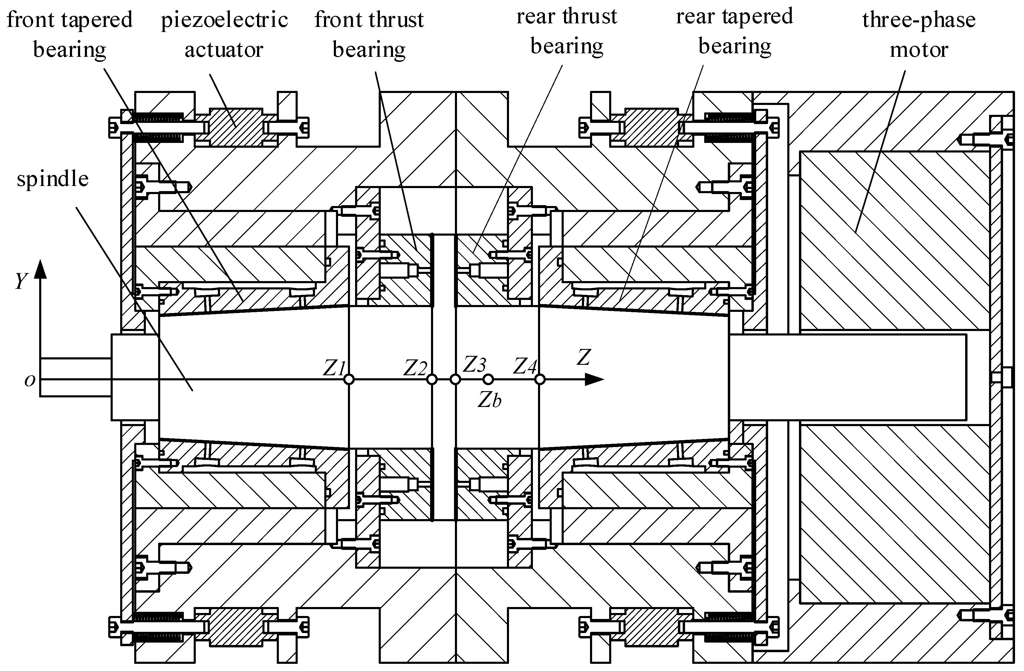
2.1. The Structure of the Aerostatic Motorized Spindle

The aerostatic motorized spindle has many structural forms, among which, according to the motor’s position, it can be divided into two structures: the middle motor and the rear motor. The research object of this paper adopts the rear motor structure, and its structural schematic diagram is shown in Figure 1. In this structure, the three-phase motor is located at the tail of the spindle and is responsible for directly driving the rotation of the spindle. Two thrust bearings are installed in the middle section of the spindle to provide axial support. The two tapered bearings are symmetrically arranged on both sides of the thrust bearings and mainly assume the function of radial support. Among them, the gas film gap of tapered bearing can be adjusted in a certain range according to different working conditions to adapt to diversified processing conditions. The adjustment mechanism’s realization process follows: the aerostatic tapered bearing is embedded in the linear bearing, and its end face is fixedly connected with the piezoelectric actuator. By adjusting the voltage of the piezoelectric actuator, the micro-displacement of the tapered bearing in the axial direction can be promoted. Because the tapered bearing has a specific taper angle, when it moves along the axial direction, it can effectively adjust the gas film gap of the bearing and realize the fine control of the bearing performance.

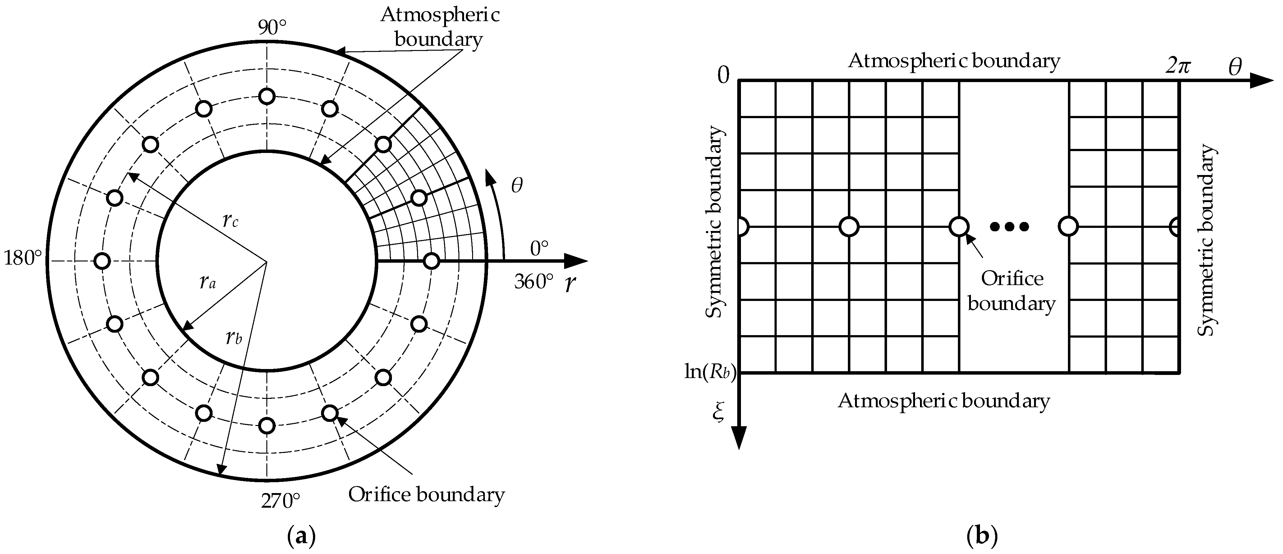
2.2. Mathematical Model of Aerostatic Thrust Bearing

2.2.1. Control Equation of Thrust Bearing

For the aerostatic thrust bearing, the solution domain of its gas film is circular, so the pressure distribution of bearing gas film can be obtained by solving the Reynolds equation in the cylindrical coordinate system, and its expression is:
1 r r r h 3 p 2 r + r 2 θ h 3 p 2 θ + 24 η p a ρ a ρ v δ i = 12 η v r ( p h ) r r + 12 η v θ ( p h ) r θ + 24 η ( p h ) t
where r and θ are radial coordinates and angular coordinates, respectively; h is the film thickness; p is the absolute gas film pressure; p a and ρ a are the gas ambient pressure and density, respectively; v r and v θ are radial velocity and circumferential velocity, respectively; η is the gas dynamic viscosity; t is time; ρ and v are the gas density and gas velocity behind the orifice, respectively; and δ i is the Kronecker function, which is 1 at the orifice nodes and 0 at the other nodes.
Because the spindle motion is rotation, the radial velocity of the spindle motion is very small and can be ignored. Therefore, Equation (1) can be expressed as:
1 r r r h 3 p 2 r + r 2 θ h 3 p 2 θ + 24 η p a ρ a ρ v δ i = 12 η v θ ( p h ) r θ + 24 η ( p h ) t
Introduce the following dimensionless parameters:
P = p / p s , H = h / h m , R = r / r a , V θ = v θ / v m
where p s is the gas supply pressure; h m is the average film thickness of the thrust bearing; r a is the radius of the inner circle of the thrust bearing; and v m is the reference speed.
The dimensionless Reynolds equation can be obtained by bringing (3) into (2):
1 R R R H 3 P 2 R + R 2 θ H 3 P 2 θ + Q δ i = Λ V θ ( P H ) R θ + σ ( P H ) t
where the expressions of Q, Ʌ, and σ are
Q = 24 η p a h m 3 p s 2 ρ a m R Δ R Δ θ , Λ = 12 η r a v m h m 2 p s , σ = 24 η r a 2 h m 2 p s
To facilitate the numerical solution, the solution domain of the thrust bearing is expanded at θ = 0 . And take ξ = ln ( R ) to perform the conformal transformation on the coordinates. The bearing circular solution domain (Figure 2a) is transformed into a rectangular solution domain (Figure 2b). By bringing the conformal transformation formula into Equation (4) and simplifying it, the Reynolds equation after coordinate transformation can be obtained:
ξ H 3 P 2 ξ + θ H 3 P 2 θ + R 2 Q δ i = Λ V θ R ( P H ) θ + R 2 σ ( P H ) t
As shown in Figure 2b, the rectangular solution domain of the thrust bearing contains three kinds of boundary conditions, namely the atmospheric boundary, orifice boundary, and symmetrical boundary. The pressure at different boundaries has the following characteristics:
P = P a a t   t h e   a t m o s p h e r i c   boundary P = P d at   the   orifice   boundary P θ = 0 at   the   symmetrical   boundary
where P a is dimensionless atmospheric pressure, and P d is dimensionless orifice pressure.

2.2.2. Flow Balance Equation

Because the Reynolds equation at the orifice nodes contains the mass flow of gas, it is necessary to introduce the flow balance equation. Its expression is as follows:
m i = ϕ A i p s 2 ρ a p a ψ i
ψ i = k 2 ( 2 k + 1 ) k + 1 k 1   β i β k k k 1 β i 2 k β i k + 1 k β i > β k
A i = π d h d 4 h π d 2 4 d 4 h
where m ˙ i is the mass flow of gas entering the gas film from a single orifice; ϕ is the mass flow coefficient, generally 0.8; A i is the orifice area, and according to the relationship between the orifice diameter and the gas film thickness at the orifice node, the gas throttling form can be divided into orifice restriction ( d / 4 h ) and toroidal restrictor ( d / 4 h ) ; ψ i is the flow function; k is the specific heat ratio of gas, and for air, k = 1.4 ; β i is the pressure ratio behind the orifice, expressed as β i = p d / p s , and p d is the pressure behind the orifices; and β k is the critical pressure ratio, and the expression is β k = ( 2 / ( k + 1 ) ) k / ( k 1 ) .

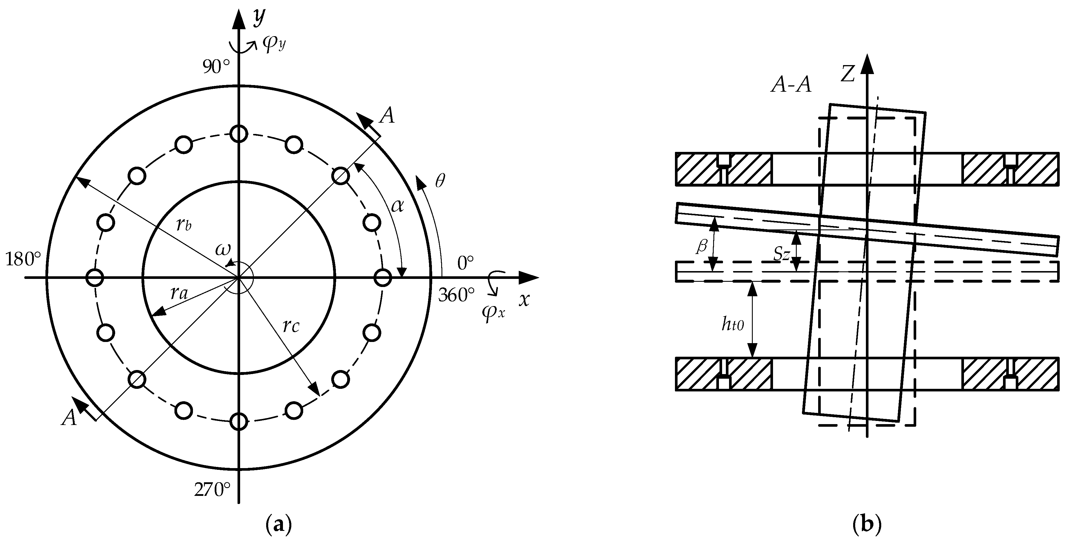
2.2.3. Gas Film Thickness Equation of Thrust Bearing

The thickness of the gas film is very important to its pressure distribution. In this research, the translation displacement of the spindle in the X direction and Y direction is very small, and the ratio of its value to the radius of the thrust bearing is about 10−4. Thus, the translation displacement of the spindle in the X direction and Y direction has very little influence on the gas film thickness of the thrust bearing, which can be ignored [13]. Therefore, the thrust bearing only contains three degrees of freedom: rotation around the X and Y axes and translation in the Z direction. Figure 3 is the schematic diagram of the aerostatic thrust bearing in the state that the shaft is inclined, and the expression for the gas film thickness of the front and rear thrust bearings is as follows:
h d = h t 0 r sin ( β ) cos ( θ α ) + S z h u = h t 0 + r sin ( β ) cos ( θ α ) S z
where h t 0 is the average film thickness of thrust bearing; β is the included angle between the spindle axis and the Z axis, α is the inclination angle, that is, the included angle between the projection of the spindle axis on the X–Y plane and the positive direction of the X axis, and its value range is 0~2π; and S z is the displacement of the spindle in the Z direction.

2.2.4. Force and Torque Equation of Thrust Bearing

The difference equation of Equation (6) is constructed by the finite difference method, and the pressure of each node in the solution domain is solved by the super relaxation iteration method. Then, by integrating the pressure, the force and torque of the thrust bearing on the spindle can be obtained.
Due to the small torsion angle of the spindle, the force components of the thrust bearing in the X and Y directions can be ignored, and the component in the Z direction is as follows:
F t d z = p s r a 2 R a R b 0 2 π P p a p s R d θ d R F t u z = p s r a 2 R a R b 0 2 π P p a p s R d θ d R
Taking the center of mass of the spindle as the rotation center, the torque expressions of the front thrust bearing in the X and Y directions are as follows:
T t d x = p s r a 3 R a R b 0 2 π P p a p s R 2 sin θ cos β d θ d R T t d y = p s r a 3 R a R b 0 2 π P p a p s R 2 cos θ cos β d θ d R
The torque expressions of the rear thrust bearing in the X and Y directions are
T t u x = p s r a 3 R a R b 0 2 π P p a p s R 2 sin θ cos β d θ d R T t u y = p s r a 3 R a R b 0 2 π P p a p s R 2 cos θ cos β d θ d R

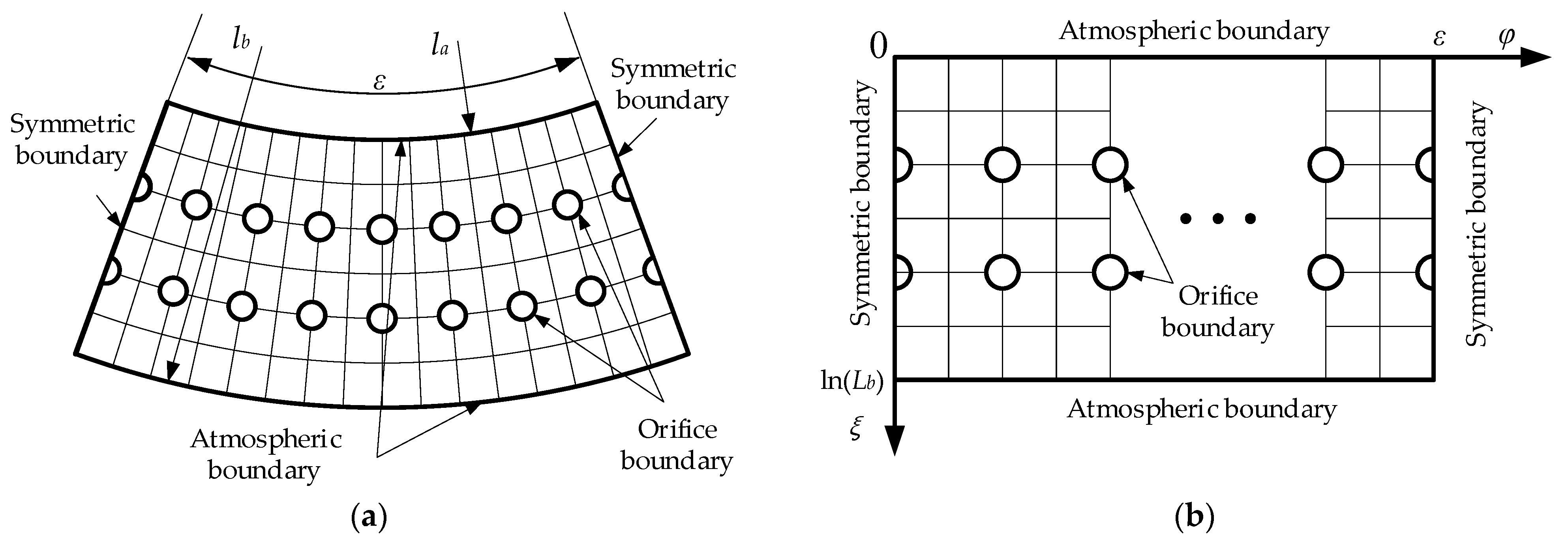
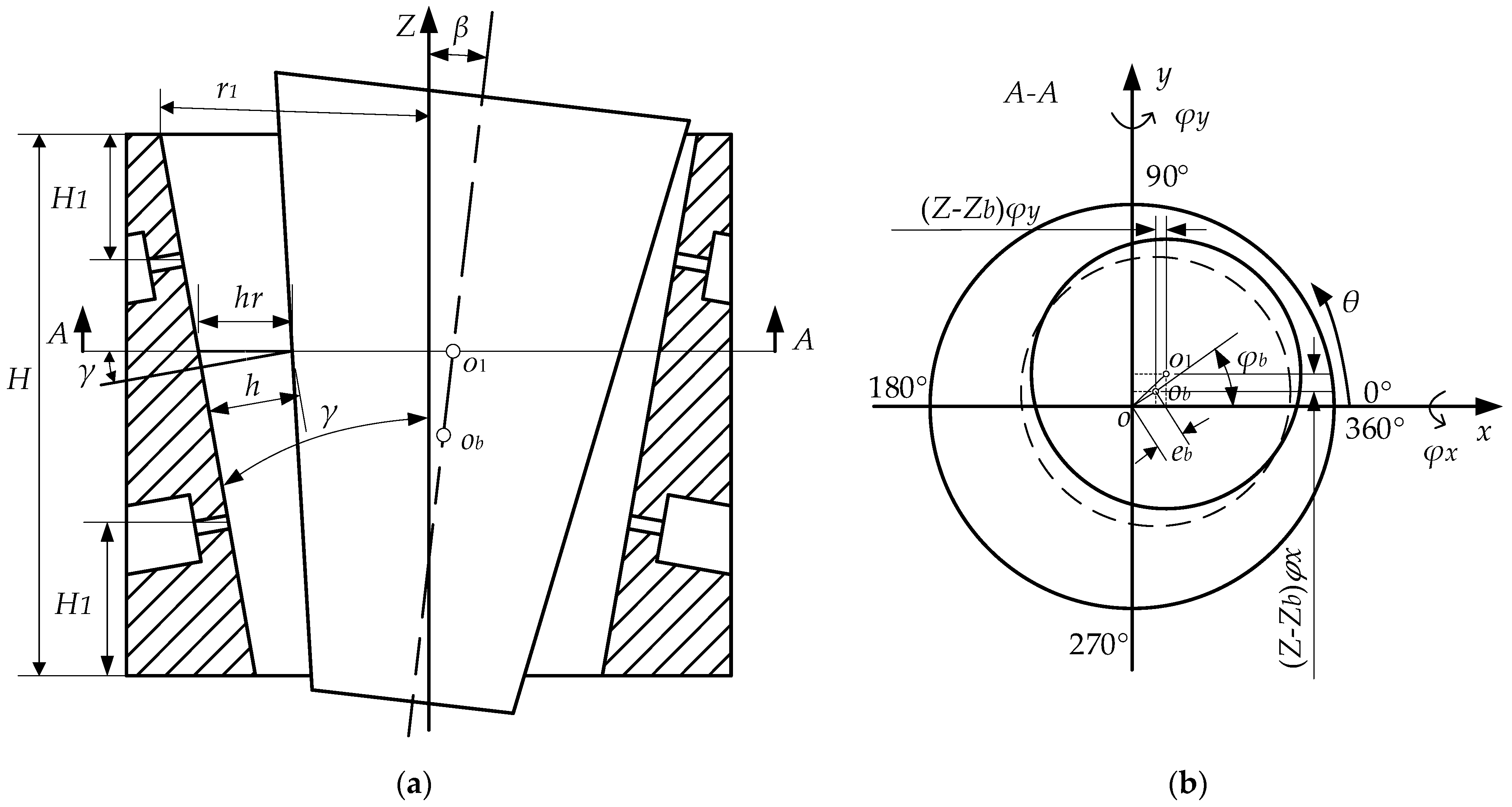
2.3. Mathematical Model of Aerostatic Tapered Bearing

2.3.1. Control Equation of Tapered Bearing

For the tapered bearing, the ratio of bearing gas film thickness to radius is about 10−4~10−3, and the influence of gas film curvature on the solution result is very small and can be completely ignored [18]. As shown in Figure 4, the tapered gas film is expanded into a plane, and the solution domain becomes a sector region (Figure 4a). Therefore, the pressure distribution in the gas film of aerostatic tapered bearings can still be obtained by solving the Reynolds equation in the cylindrical coordinate system. Through the using same derivation process as that in Equations (1) to (6) and introducing dimensionless Equation (15) and conformal transformation formula ζ = ln ( L ) , the rectangular solution domain (Figure 4b) and control Equation (16) can be obtained. For the rectangular solution domain of tapered bearing shown in Figure 4b, the boundary conditions are exactly the same as those of thrust bearing, so please refer to Equation (7).
P = p / p s , H = h / h j 0 , L = l / l a , V φ = v φ / v m
ζ H 3 P 2 ζ + φ H 3 P 2 φ + L 2 δ i Q = Λ V φ L ( P H ) φ + L 2 σ ( P H ) t
where
Q = 24 η p a h j 0 3 p s 2 ρ a m L Δ L Δ φ , Λ = 12 η l a v m h j 0 2 p s , σ = 24 η l a 2 h j 0 2 p s

2.3.2. Gas Film Thickness Equation of Tapered Bearing

For the tapered aerostatic bearing its structural schematic diagram is shown in Figure 5, and its gas film thickness equation is as follows:
h = ( h j 0 Δ z tan γ e b cos ( θ ϕ b ) ( z z b ) ( φ y cos θ + φ x sin θ ) ) cos γ
where h j 0 is the maximum radial gas film thickness, that is, the radial gas film thickness of the tapered bearing without the adjustment of the piezoelectric actuator; Δ z is the axial displacement of the bearing seat body under the action of the piezoelectric actuator; γ is the half-cone angle of the tapered bearing; e b is the eccentricity of the center of mass of the spindle position; ϕ b is the offset angle of the spindle, and its value range is 0~2π; z b is the axial coordinate of the position of the center of mass; and φ x and φ y , respectively, represent the angular displacement of the spindle axis around the X axis and the Y axis when the center of mass is the rotation center.

2.3.3. Force and Torque Equation of Tapered Bearing

The pressure distribution in the tapered gas bearing can be obtained from Equation (16). The tapered bearing capacity in X, Y, and Z directions can be obtained by integrating the gas film pressure. At the same time, taking the center of mass of the spindle as the rotation center, the torque expressions of each bearing force relative to the center of mass can be listed.
For the front tapered bearing, the component expression of force in all directions is as follows:
F j d x = p s l a 2 L a L b 0 ε P p a p s cos γ cos θ L d φ d L F j d y = p s l a 2 L a L b 0 ε P p a p s cos γ sin θ L d φ d L F j d z = p s l a 2 L a L b 0 2 π P p a p s sin γ L d φ d L
For the rear tapered bearing, the component expression of force in all directions is as follows:
F j u x = p s l a 2 L a L b 0 ε P p a p s cos γ cos θ L d φ d L F j u y = p s l a 2 L a L b 0 ε P p a p s cos γ sin θ L d φ d L F j u z = p s l a 2 L a L b 0 ε P p a p s sin γ L d φ d L
The torque expressions of the front tapered bearing in X direction and Y direction are as follows:
T j d x = p s l a 2 L a L b 0 ε z i z b P p a p s cos γ sin θ L d φ d L T j d y = p s l a 2 L a L b 0 ε z i z b P p a p s cos γ cos θ L d φ d L
The expressions of the torque T j u x in the X direction and the torque T j u y in the Y direction of the rear tapered bearing are the same as those of the front tapered bearing, so they will not be explained separately here.

2.4. Spindle Motion Equation

When the center of mass is the rotation center of the spindle, and the gas damping is ignored, the translation motion equation and rotation motion equation of the spindle can be further derived from the Newton–Euler equation. The equations are as follows:
S ¨ = F j d x + F j u x + F e x M g F j d y + F j u y + F e y + G M g F t d z + F t u z + F j d z + F j u z + F e z M g T t d x + T t u x + T j d x + T j u x + T e x I y I z φ y ω I x T t d y + T t u y + T j d y + T j u y + T e y I z I x ω φ x I y
S ˙ = S ˙ 0 + S ¨ Δ t
S = S 0 + S ˙ 0 Δ t + 1 2 S ¨ Δ t 2
S = S X S Y S Z φ x φ y
where S , S ˙ and S ¨ are the displacement, velocity, and acceleration, respectively; S 0 and S ˙ 0 are the displacement and velocity at the previous moment, respectively; F e x , F e y , and F e z are the components of the external force on the spindle in the X, Y, and Z directions, respectively; M g is the spindle mass; I x , I y , and I z are the torque of inertia of the spindle in the X, Y, and Z directions, respectively; S X , S Y , and S Z are the translational displacement at the center of mass; and φ x and φ y are the angular displacements of the spindle, with the center of mass as the rotation center.
For any point with coordinate z on the spindle axis, the offset in the three-dimensional coordinate system can be expressed as follows:
S = S X S Y S Z = S X z z b φ y S Y + z z b φ x S Z

3. Numerical Solution

3.1. Model Parameters

Table 1, Table 2, Table 3 and Table 4 show the main structural and gas parameters of the model used in this paper, and the specific values are as follows.

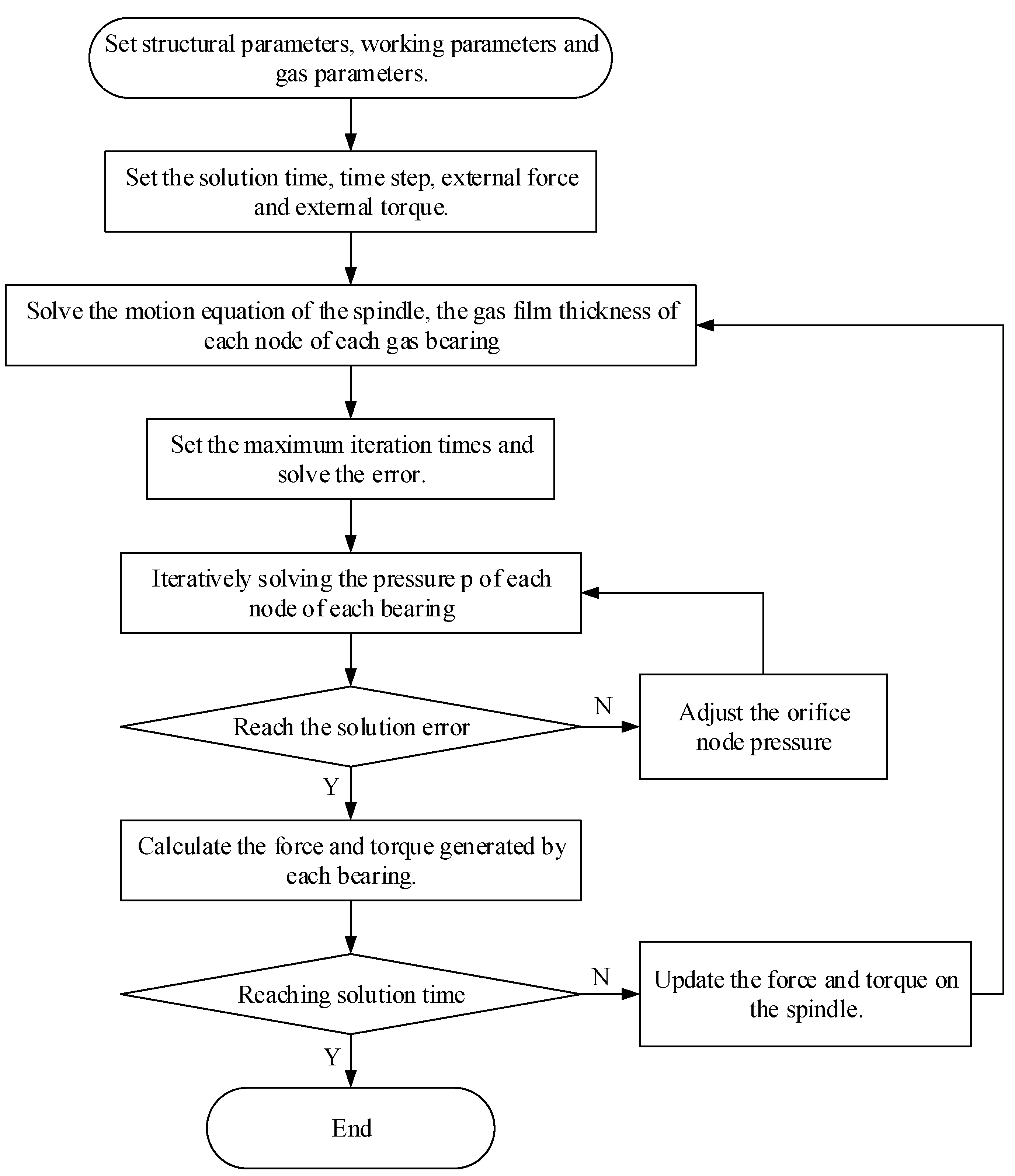
3.2. Calculation Process

For the solution domain of the aerostatic bearing shown in Figure 2 and Figure 4, the number of grids greatly influences the accuracy of the solution results. Too few grids will lead to too large an solution error, while too many will lead to too long a calculation time and low a calculation efficiency. Therefore, before the dynamic solution of the spindle motion, it is necessary to determine the number of grids in the solution domain of the aerostatic bearing. To solve the above problems, the grid-independent verification of the solution domain of the aerostatic bearing is carried out based on the steady-state solution results of the aerostatic bearing. Set the convergence condition of dimensionless pressure as P i , j n + 1 P i , j n 10 6 . And keep the number of circumferential grid nodes in the tapered bearing solution domain and the thrust bearing solution domain the same. The grid is encrypted by constantly doubling the number of grids in two coordinate directions in the solution domain. When the axial force errors of thrust bearing and tapered bearing obtained after two adjacent grid changes are within 2%, the number of grids is considered to meet the solution requirements. Finally, it is determined that the mesh number m j × n j of the tapered bearing is 160 × 80, and the mesh number m t × n t of the thrust bearing is 160 × 60.
The motion solution process of the spindle is shown in Figure 6. Taking the state when the translational displacement and angular displacement of the spindle are all zero as the initial state of motion, the steady-state gas film pressure of each bearing at the initial state is solved, and the result is taken as the initial value of transient gas film pressure. In the transient solution, the courant number is used to determine the time step and its expression is C = U Δ t / Δ x . In order to ensure the convergence of the solution process, C = 2 is taken here. After calculation, when the spindle speed is 40,000 RPM, Δ t 0.02   ms is obtained based on the linear velocity of the big end of the tapered bearing and the grid size. Through the over-relaxation iteration method, the pressure values of all nodes are solved, and the pressure values of all nodes are adjusted so that the solution results gradually converge until the pressure values meet the error requirements. On this basis, the force and torque generated by each bearing on the spindle are solved, and the dynamic motion trajectory of the spindle is solved by constantly updating the motion equation of the spindle until the total time is reached and the calculation stops.

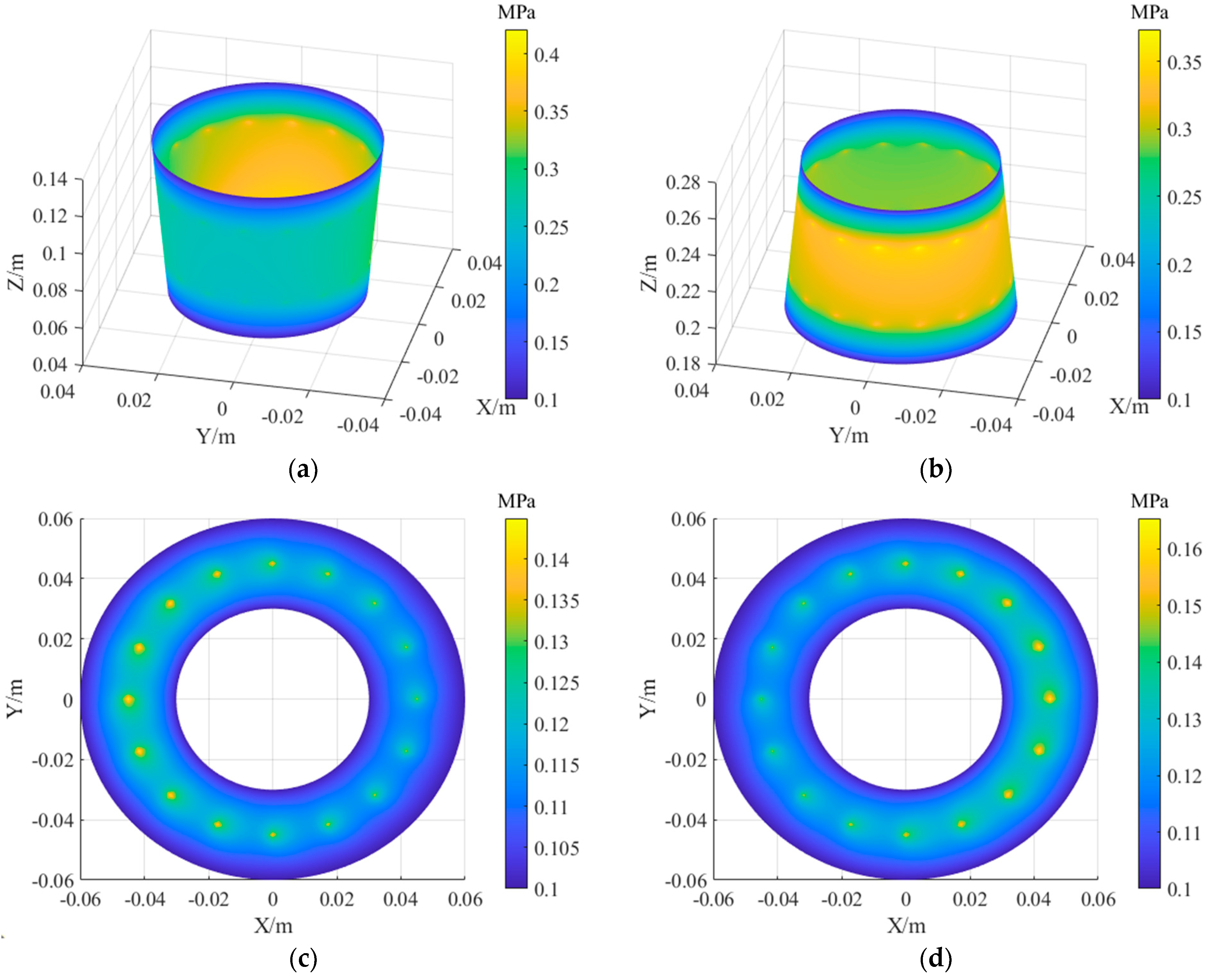
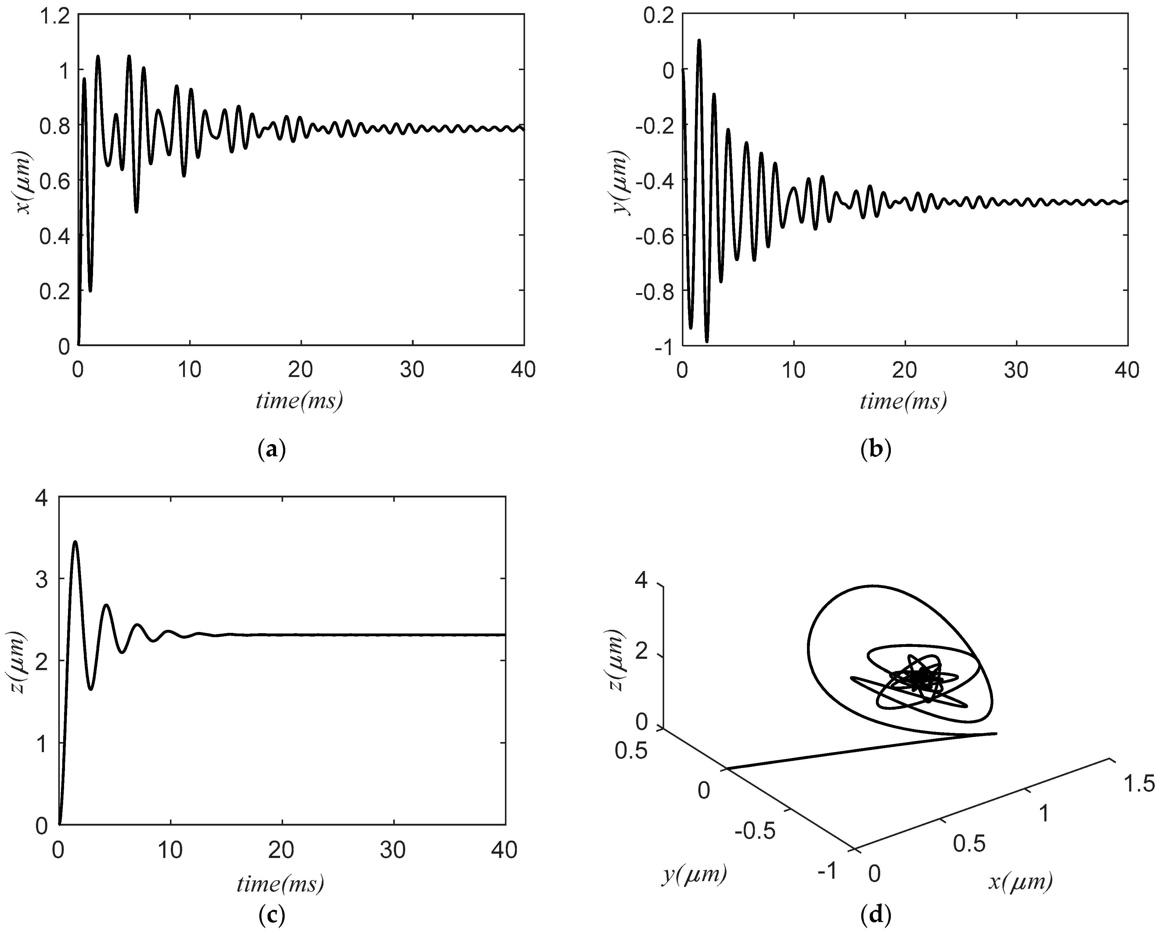
3.3. Result and Analysis

The ultra-high-speed grinder is the main application equipment of the aerostatic motorized spindle. Generally speaking, an ultra-high-speed grinder requires the linear speed of the grinding wheel to be greater than 150 m/s and the spindle speed to be greater than 10,000 RPM, and the higher the spindle speed, the higher the grinding efficiency. Taking the speed range of the ultra-high-speed grinder as an example, this paper analyzes the influence of spindle tilting motion on the pressure distribution and its own motion characteristics of the aerostatic bearing through three sets of simulation results and the influence of gas film thickness of gas bearing on the nonlinear vibration and motion stability of spindle under two different cutting conditions of low-speed heavy load and high-speed light load. In addition, due to the actual use of aerostatic bearings, the gas supply pressure is usually between 0.3 and 0.8 MPa. Too low gas supply pressure will reduce the stiffness of the spindle, while too high air supply pressure will easily lead to the instability of the spindle. Therefore, the gas supply pressure of the gas bearings is set to 0.5 MPa and 0.6 MPa in this paper.

3.3.1. Situation 1

The film thickness of the tapered bearing is 25 μm, the gas supply pressure is 0.5 MPa, and the spindle speed is 30,000 RPM. The external load acts on the front end of the spindle ( z = 0 ), and the external force and torque on the spindle are F e x = 100   N , F e y = 0 , F e z = 50   N , T e x = 0 , and T e y = 16.7   N · m , and the gravity G points in the negative direction along the Y axis. Other parameters are shown in Table 1, Table 2, Table 3 and Table 4, and the simulation results are as follows.
Comparing the coordinate distribution of gas film pressure along the X axis of the two tapered bearings in Figure 7a,b, it can be seen that the pressure difference in the front tapered bearing is larger than that of the rear tapered bearing, which is mainly due to the deflection of the spindle around the positive direction of the Y axis under the action of external torque, resulting in the gradual decrease in the gas film thickness of the front tapered bearing along the positive direction of the X axis. In contrast, the gas film thickness of the rear tapered bearing gradually increases along the positive direction of the X axis. At the same time, because the front tapered bearing is relatively far from the rotation center, the gas film offset is larger, so the pressure difference in the gas film is more obvious. From the observation of Figure 7c,d, it can be seen that the pressure of the front thrust bearing is lower than that of the rear thrust bearing. This is because the spindle moves to the positive direction of the Z axis under the action of external load, which makes the gas film thickness of the rear thrust bearing smaller than that of the front thrust bearing. Hence, the pressure in the gas film of the rear thrust bearing is greater. In addition, due to the tilting motion of the spindle, the gas film thickness in the circumferential direction of the two thrust bearings is different, which makes the pressure distribution obviously different.
As seen in Figure 8a, the front end of the spindle is affected by external load along the positive direction of the X axis, which makes the spindle shift to the positive direction of the X axis. Therefore, the vibration at the center of mass of the spindle occurs in the positive direction of the X axis, and its vibration curve shows serious nonlinearity under the influence of the nonlinear gas film force of the tapered bearing. The variation law of the vibration curve is somewhat similar to that of beat vibration, but with the increase in time, its vibration amplitude gradually decreases, and finally it basically tends to be stable and only fluctuates in a small range near the equilibrium position. As can be seen from Figure 8b, under the influence of the gravity of the spindle, the center of mass of the spindle will move in the negative direction of the Y axis. Similarly, under the joint action of nonlinear gas film force, the center of mass of the spindle produces nonlinear vibration in the negative direction of the Y axis, and the variation law of its vibration curve is similar to that of the vibration curve in the X direction. It can be seen from Figure 8c that the spindle deviates to the positive direction of the Z axis under the action of external load, and its vibration curve is similar to the underdamped vibration. With the increase in time, the amplitude gradually decreases, and finally, the vibration gradually disappears. Figure 8d shows the movement track of the spindle center of mass in the three-dimensional coordinate system. It can be seen from the figure that the center of mass of the spindle moves from the initial position and quickly stabilizes in a small range of motion.
Figure 9a shows that the angular displacement of the spindle axis around the X axis is negative. The main reason for this phenomenon is that the center of mass of the spindle is closer to the rear tapered bearing, and the lever arm of each node of the rear tapered bearing relative to the center of mass of the spindle is shorter than that of the front tapered bearing. Therefore, to balance the torque generated by the gas film force of the front tapered bearing relative to the center of mass of the spindle, the rear tapered bearing needs to provide more gas film force. Therefore, when the spindle rotates around the negative direction of the X axis, the eccentricity of the gas film of the rear tapered bearing in the negative direction of the Y axis is greater, which can provide greater gas film force, thus balancing the torque generated by the front tapered bearing. As can be seen from Figure 9b, the angular displacement of the spindle rotating around the Y axis is positive. The main reason is that when the front end of the spindle receives an external load along the positive direction of the X axis, it will generate a torque around the positive direction of the Y axis, and under the action of the rotating torque, the spindle rotates around the Y axis in the positive direction. After a period of torsional vibration, it gradually stabilized near the angular equilibrium position.

3.3.2. Situation 2

Adjust the gas film thickness of the tapered bearing to be 20 μm and 25 μm; the gas supply pressure is 0.6 MPa, the spindle speed is 20,000 RPM, Fex = 200 N, Fey = 0, Fez = 50 N, Tex = 0, Tey = 33.4 N·m, and the simulation results are shown in Figure 10.
As shown in Figure 10, according to the translational displacement curve and angular displacement curve at the center of mass of the spindle in Situation 2, under the same external excitation, the amplitude of the spindle corresponding to the 20 μm bearing is small, and the offset of the vibration center is small. However, although the vibration amplitude and vibration center offset of the spindle corresponding to the 25 μm bearing is large, the vibration attenuation is faster, and the response time to achieve stability again is shorter. The main reasons for this phenomenon are as follows: when the thickness of the bearing gas film is small, the stiffness of the bearing is large, so under the same external load, the amplitude and vibration center offset of the spindle are small. When the gas film thickness of the bearing is large, the stiffness of the bearing will decrease, and the amplitude and vibration center offset of the spindle will be large, but the damping characteristics of the bearing will be increased, making the vibration attenuation of the spindle faster and the stable response time shorter.

3.3.3. Situation 3

Adjust the gas film thickness of the tapered bearing to 20 μm and 25 μm, the gas supply pressure to 0.5 MPa, and the spindle speed to 40,000 RPM; Fex = 100 N, Fey = 0, Fez = 50 N, Tex = 0, Tey = 16.7 N·m, and the simulation results are shown in Figure 11.
As shown in Figure 11, in Situation 3, the vibration curves of the spindle supported by bearings with different gas film thicknesses show significant differences. Specifically, the curves of translation displacement and angular displacement vibration of the spindle corresponding to the bearing with a 20 μm gas film thickness show a gradually divergent trend, so it can be inferred that the motion state of the spindle will tend to be unstable with the passage of time. In contrast, the vibration curve of the spindle corresponding to the bearing with a 25 μm gas film thickness shows the characteristics of slow convergence, which indicates that the system still maintains a stable running state under this working condition. A further analysis of Figure 11 shows that in the initial stage of vibration, the vibration amplitude and vibration center offset of the spindle corresponding to the bearing with a larger gas film thickness are large, which is consistent with the variation law of the vibration curve in Situation 2. In this study, it is considered that there are two main factors leading to the above-mentioned difference in vibration characteristics: Firstly, as mentioned in Situation 2, the increase in gas film thickness is helpful to improve the damping characteristics of bearings, thus enhancing the stability of the system and raising the stability threshold of spindle speed. Secondly, when the spindle speed is too high, the dynamic pressure effect of gas bearing will be intensified. For bearings with small gas film thickness, under the condition of eccentricity, the film wedge is larger, and the dynamic pressure effect is more obvious. For bearings with large gas film thickness, the film wedge caused by eccentricity is smaller, and the influence of the dynamic pressure effect is relatively weak, so the stability of the system is better.

4. Discussion

Different working conditions have different requirements for the performance of the aerostatic motorized spindle. By adjusting the gas film thickness of the bearing to increase the stability of the spindle, the aerostatic motorized spindle can have better applicability. In addition, in the work engineering of the aerostatic motorized spindle, under the action of external load, torque, and gravity, the spindle will tilt, affecting the pressure distribution of the aerostatic bearing and the spatial attitude of the spindle. The change in the spatial attitude of the spindle may cause system instability and even cause a collision between the spindle and the bearing seat in serious cases.
In previous studies, journal bearings were often used as the radial support of the spindle, and the thickness of the bearing gas film could not be adjusted, resulting in the poor applicability of the aerostatic motorized spindle. In addition, in some studies, the influence of the tilting motion of the spindle on the performance of the bearing rotor system is ignored, which makes the theoretical model deviate greatly from the actual situation. Based on the above problems, we believe that the tapered bearing can be used as the radial support of the spindle instead of the journal bearing, and the gas film gap of the tapered bearing can be adjusted in a certain range through the corresponding axial adjustment device to meet more working conditions and processing requirements. At the same time, due to the tilting motion of the spindle, the gas film thickness of the bearing will be greatly affected, thus affecting the gas film pressure distribution and spindle motion. Therefore, in mathematical modeling, the influence of spindle tilting motion on system stability must be considered. By solving the motion equation of the spindle, we can not only quantitatively analyze the radial and axial runout of the spindle but also analyze the threshold speed of the system and judge its stability.
The simulation results show that when the spindle is externally excited, its displacement curve and angular displacement curve all show nonlinear vibration, and for different working conditions and parameters, the system may eventually reach a stable state after external excitation, or it may cause system instability. Therefore, we believe that the modeling method can be used to study the self-excited vibration of gas bearings. In addition, during the simulation calculation, it was found that the aerostatic motorized spindle contains multiple bearings. To ensure the solution accuracy, it is required that the number of grids be large enough and the solution error and time step be small enough. The above reasons make the model solution more complicated, and the solution process takes a long time. How to conduct numerical calculations more efficiently and correctly is also a problem that needs further study.
In this paper, the mathematical model of a 5-DOF bearing rotor system is established, and the influence of spindle tilting motion on system stability is considered. Although it is close to the actual working state of the aerostatic spindle to a certain extent, some improvements can still be made. For example, the unbalanced magnetic pull of the motor caused by eccentric and inclined motion is not considered in the modeling process [19,20], nor the influence of bearing surface quality on bearing performance and system stability during processing and manufacturing [21,22]. In addition, because the parts of the aerostatic motorized spindle require high machining accuracy, the manufacturing process is complex, and the test-bed construction takes a long time; at present, the theoretical analysis in this paper does not have the conditions for experimental verification. This part will be carried out in the follow-up work.

5. Conclusions

In this paper, the aerostatic tapered bearing is used as the radial support of the aerostatic motorized spindle, and the gas film gap of the tapered bearing can be adjusted in a certain range through the axial adjustment device, thus improving the applicability of the motorized spindle under different working conditions. At the same time, the mathematical model of a 5-DOF bearing rotor system is established, considering the tilting motion of the motorized spindle in the actual working process. The calculation equations of bearing gas film thickness in the state of spindle tilting motion are derived, and the gas film pressure distribution, spindle translational displacement, and angular displacement curves are obtained through numerical calculation. The simulation results show that the tilting motion of the spindle changes the gas film thickness of the gas bearings, which significantly affects the gas film’s pressure distribution, making the rotor’s displacement curve show serious nonlinearity under the action of nonlinear gas film force. In addition, by comparing the vibration curves of the aerostatic spindle under different working conditions in Situation 2 and Situation 3, it is concluded that the bearing stiffness with small film thickness is greater, and the vibration amplitude and offset of spindle under low speed and heavy load are smaller. The bearing with large gas film thickness has better damping characteristics, so the system stability is better under high speed and light load conditions. It can be seen that the optimal gas film thickness of the corresponding bearing is different under different working conditions.

Author Contributions

Conceptualization, C.J. and S.J.; methodology, S.J.; software, S.J. and Y.L.; validation, C.J.; formal analysis, S.J.; investigation, Y.L. and S.J.; data curation, Y.L.; writing—original draft preparation, S.J.; writing—review and editing, S.J.; visualization, Y.L. and S.J.; funding acquisition, C.J. All authors have read and agreed to the published version of the manuscript.

Funding

This research was funded by the National Key Research and Development Program of China, grant number 2022YFB3402704.

Data Availability Statement

The data presented in this study are available on reasonable request from the corresponding author.

Conflicts of Interest

The authors declare no conflicts of interest.

References

  1. Liu, Z.F.; Wang, Y.M.; Cai, L.G.; Zhao, Y.S.; Cheng, Q.; Dong, X.M. A review of hydrostatic bearing system: Researches and applications. Adv. Mech. Eng. 2017, 9, 168781401773053. [Google Scholar] [CrossRef]
  2. Chen, G.; Ju, B.; Fang, H.; Chen, Y.; Yu, N.; Wan, Y. Air bearing: Academic insights and trend analysis. Int. J. Adv. Manuf. Technol. 2019, 106, 1191–1202. [Google Scholar] [CrossRef]
  3. Gao, Q.; Chen, W.Q.; Lu, L.H.; Huo, D.H.; Cheng, K. Aerostatic bearings design and analysis with the application to precision engineering: State-of-the-art and future perspectives. Tribol. Int. 2019, 135, 1–17. [Google Scholar] [CrossRef]
  4. Zhang, J.B.; Deng, Z.F.; Zhang, K.; Jin, H.L.; Yuan, T.; Chen, C.; Su, Z.M.; Cao, Y.T.; Xie, Z.L.; Wu, D.Y.; et al. The Influences of Different Parameters on the Static and Dynamic Performances of the Aerostatic Bearing. Lubricants 2023, 11, 130. [Google Scholar] [CrossRef]
  5. Zhang, S.; Yu, J.; To, S.; Xiong, Z. A theoretical and experimental study of spindle imbalance induced forced vibration and its effect on surface generation in diamond turning. Int. J. Mach. Tools Manuf. 2018, 133, 61–71. [Google Scholar] [CrossRef]
  6. Chen, D.J.; Huo, C.; Cui, X.X.; Pan, R.; Fan, J.W.; An, C.H. Investigation the gas film in micro scale induced error on the performance of the aerostatic spindle in ultra-precision machining. Mech. Syst. Signal Proc. 2018, 105, 488–501. [Google Scholar] [CrossRef]
  7. Zhang, S.J.; To, S.; Cheung, C.F.; Wang, H.T. Dynamic characteristics of an aerostatic bearing spindle and its influence on surface topography in ultra-precision diamond turning. Int. J. Mach. Tools Manuf. 2012, 62, 1–12. [Google Scholar] [CrossRef]
  8. Wen, Z.P.; Gu, H.; Shi, Z.Y. Key Technologies and Design Methods of Ultra-Precision Aerostatic Bearings. Lubricants 2023, 11, 315. [Google Scholar] [CrossRef]
  9. Li, J.; Liu, P. Dynamic analysis of 5-DOFs aerostatic spindles considering tilting motion with varying stiffness and damping of thrust bearings. J. Mech. Sci. Technol. 2019, 33, 5199–5207. [Google Scholar] [CrossRef]
  10. Zhao, X.L.; Dong, H.; Fang, Z.; Chen, D.D.; Zhang, J.A. Study on Dynamic Characteristics of Aerostatic Bearing with Elastic Equalizing Pressure Groove. Shock Vib. 2018, 2018, 989. [Google Scholar] [CrossRef]
  11. Chen, D.; Li, N.; Pan, R.; Han, J. Analysis of aerostatic spindle radial vibration error based on microscale nonlinear dynamic characteristics. J. Vib. Control. 2019, 25, 2043–2052. [Google Scholar] [CrossRef]
  12. Lei, Q.; Yuan, Y.; Du, J.; LI, L. Study on Rotor Dynamics Characteristics of High Speed Aerostatic Motorized Spindle during Fly-cutter Milling Process. J. Mech. Eng. 2021, 57, 45–54. [Google Scholar]
  13. Shi, J.H.; Cao, H.R.; Jin, X.L. Dynamics of 5-DOF aerostatic spindle with time-varying coefficients of air bearing. Mech. Syst. Signal Proc. 2022, 172, 109005. [Google Scholar] [CrossRef]
  14. Zhang, G.-H.; Sun, Y.; Liu, Z.-S.; Zhang, M.; Yan, J.-J. Dynamic characteristics of self-acting gas bearing–flexible rotor coupling system based on the forecasting orbit method. Nonlinear Dyn. 2011, 69, 341–355. [Google Scholar] [CrossRef]
  15. Wu, Y.; Feng, K.; Zhang, Y.; Liu, W.; Li, W. Nonlinear dynamic analysis of a rotor-bearing system with porous tilting pad bearing support. Nonlinear Dyn. 2018, 94, 1391–1408. [Google Scholar] [CrossRef]
  16. Chen, G.D.; Chen, Y.J. Multi-Field Coupling Dynamics Modeling of Aerostatic Spindle. Micromachines 2021, 12, 251. [Google Scholar] [CrossRef] [PubMed]
  17. Feng, K.; Li, J.; Li, W.; Huang, J.; Gao, F.; Sun, J. A novel parallel capillary-cavity model for the analysis of pneumatic hammer vibration in porous aerostatic bearings. Tribol. Int. 2023, 189, 108993. [Google Scholar] [CrossRef]
  18. Gao, S.; Cheng, K.; Chen, S.; Ding, H.; Fu, H. Computational design and analysis of aerostatic journal bearings with application to ultra-high speed spindles. Proc. Inst. Mech. Eng. C J. Mech. Eng. Sci. 2016, 231, 1205–1220. [Google Scholar] [CrossRef]
  19. Chen, G.; Chen, Y.; Lu, Q.; Wu, Q.; Wang, M. Multi-Physics Fields Based Nonlinear Dynamic Behavior Analysis of Air Bearing Motorized Spindle. Micromachines 2020, 11, 723. [Google Scholar] [CrossRef]
  20. Wu, Q.; Sun, Y.; Chen, W.; Wang, Q.; Chen, G. Theoretical prediction and experimental verification of the unbalanced magnetic force in air bearing motor spindles. Proc. Inst. Mech. Eng. B J. Eng. Manuf. 2019, 233, 2330–2344. [Google Scholar] [CrossRef]
  21. Sun, F.; Zhang, X.; Wang, X.; Su, Z.; Wang, D. Effects of Shaft Shape Errors on the Dynamic Characteristics of a Rotor-Bearing System. J. Tribol. 2019, 141, 101701. [Google Scholar] [CrossRef]
  22. Zhang, G.; Zheng, J.; Yu, H.; Chen, T.; Zhang, K.; Dou, G. Evaluation of the Influence of Shaft Shape Errors on the Rotation Accuracy of Aerostatic Spindle—Part 1: Modeling. Electronics 2022, 11, 1304. [Google Scholar] [CrossRef]
Figure 1. Structural diagram of the aerostatic motorized spindle.
Lubricants 12 00424 g001
Figure 2. Solution domain of thrust bearing: (a) circular solution domain; (b) rectangular solution domain.
Lubricants 12 00424 g002
Figure 3. The schematic diagram of the thrust-bearing gas film under spindle inclination: (a) bearing front view; (b) bearing profile.
Lubricants 12 00424 g003
Figure 4. Solution domain of the tapered bearing: (a) sector solution domain; (b) rectangular solution domain.
Lubricants 12 00424 g004
Figure 5. Schematic diagram of the tapered bearing structure under spindle inclination: (a) bearing profile; (b) cross section of gas film.
Lubricants 12 00424 g005
Figure 6. Calculation process diagram of spindle motion.
Lubricants 12 00424 g006
Figure 7. Cloud chart of gas bearings pressure: (a) front tapered bearing; (b) rear tapered bearing; (c) front thrust bearing; (d) rear thrust bearing.
Lubricants 12 00424 g007
Figure 8. Translation displacement of spindle center of mass: (a) X direction displacement; (b) Y direction displacement; (c) Z direction displacement; (d) motion trajectory in three-dimensional coordinates.
Lubricants 12 00424 g008
Figure 9. Angular displacement of the spindle axis: (a) angular displacement around the X axis; (b) angular displacement around the Y axis.
Lubricants 12 00424 g009
Figure 10. Displacement curve of Situation 2: (a) translational displacement in the X direction; (b) translational displacement in the Y direction; (c) angular displacement around the X axis; (d) angular displacement around the Y axis.
Lubricants 12 00424 g010
Figure 11. Displacement curve of Situation 3: (a) translational displacement in the X direction; (b) translational displacement in the Y direction; (c) angular displacement around the X axis; (d) angular displacement around the Y axis.
Lubricants 12 00424 g011
Table 1. Main structural parameters of Spindle.
ParameterValue
Spindle length ( L 0 )340 mm
Spindle mass ( M g )5.6 Kg
X direction torque of inertia ( I x )31.18 g.m2
Y direction torque of inertia ( I y )31.18 g.m2
Z direction torque of inertia ( I z )3.27 g.m2
Center of mass position ( Z b )167 mm
Position of front tapered bearing ( Z 1 )130 mm
Position of front thrust bearing ( Z 2 )150 mm
Position of rear thrust bearing ( Z 3 )160 mm
Position of rear tapered bearing ( Z 4 )180 mm
Table 2. Main structural parameters of thrust bearing.
ParameterValue
Radius of the inner circle ( r a )30 mm
Radius of the external circle ( r b )60 mm
Radius of distribution circle ( r c )45 mm
Number of orifices ( N t )16
Orifice diameter ( d t )0.12 mm
Average film thickness ( h m )20 μm
Table 3. Main structural parameters of tapered bearing.
ParameterValue
Big end radius ( r 1 )30 mm
Height (H)80 mm
Half-cone angle ( γ )
Number of orifices ( N j )16
Orifice diameter ( d j )0.12 mm
Radial maximum film thickness ( h j 0 )25 μm
Axial adjustment ( Δ z )0~100 μm
Distance from orifice to end face ( H 1 )20 mm
Table 4. Gas parameters.
ParameterValue
Gas supply pressure ( p s )0.3~0.8 MPa
Atmospheric pressure ( p a )0.1 MPa
Gas density at ambient pressure ( ρ a )1.204 Kg/m3
Gas dynamic viscosity ( η ) 1.82 × 10 5   N s / m 2
Ratio of Specific Heat ( k )1.4
Gas temperature ( T )293 K
Disclaimer/Publisher’s Note: The statements, opinions and data contained in all publications are solely those of the individual author(s) and contributor(s) and not of MDPI and/or the editor(s). MDPI and/or the editor(s) disclaim responsibility for any injury to people or property resulting from any ideas, methods, instructions or products referred to in the content.

