Article

Wear and Friction Characteristics of In Situ TiC-Reinforced Ti3SiC2-Ti5Si3 Composites Against 100Cr6 Steel Counterpart

by
Abdessabour Benamor
1,2,*,
Hiba Benamor
1,
Youcef Hadji
1,
Maharshi Dey
3,*,
Nabil Chiker
1,
Adel Haddad
1,
Riad Badji
2,
Arnaud Tricoteaux
4,
Jean-Pierre Erauw
5,
Merouane Salhi
6 and
Mohamed Hadji
1,2
1
Laboratoire d’Etudes et Recherche en Technologie Industrielle (LERTI), University of Blida 1, BP 270, Route de Soumaa, Blida 09000, Algeria
2
Research Center in Industrial Technologies CRTI, P.O. Box 64, Cheraga, Algiers 16014, Algeria
3
UbiQD, Inc., Los Alamos, NM 87544, USA
4
LMCPA—Laboratoire des Matériaux Céramiques et Procédés Associés, Université Polytechnique Hauts de France, Bd Charles de Gaulle, 59600 Maubeuge, France
5
The Belgian Ceramic Research Centre (BCRC), Avenue Gouverneur Cornez 4, B-7000 Mons, Belgium
6
Laboratory of Energetic Process and Nanotechnologies (LPEN), University of Blida 1, BP 270, Route de Soumaa, Blida 09000, Algeria
*
Authors to whom correspondence should be addressed.
Lubricants 2024, 12(11), 368; https://doi.org/10.3390/lubricants12110368
Submission received: 26 September 2024 / Revised: 15 October 2024 / Accepted: 20 October 2024 / Published: 24 October 2024

Abstract

In this study, the dry sliding characteristics of a Ti3SiC2/Ti5Si3 matrix reinforced with different TiC contents against a 100Cr6 steel ball were investigated. The composites were fabricated using the spark plasma sintering method with Ti, SiC, and C powders. SEM revealed that the composites possessed damage tolerance behavior, where grain pull-out, buckling, delamination, and diffuse microcracking were observed. In comparison, the unreinforced composite showed severe adhesive wear and tribo-oxidative wear mechanisms. The integration of the TiC phase in the Ti3SiC2/Ti5Si3 matrix enhanced the wear resistance by at least one order of magnitude. A new wear regime was observed in the TiC-reinforced composites, classified as mild wear, where tribo-oxidation and third-body abrasion were dominant, with ferrous deposits on the sliding surfaces.

Graphical Abstract

1. Introduction

Ceramics, known for their high-temperature resistance, low density, and corrosion resistance [1], find extensive use in applications requiring specific mechanical properties. Ceramic matrix composites (CMCs) are widely used in applications where high compressive strength, specific stiffness, and fatigue strength are necessary [2].
The emergence of MAX phases, nano-layered ternary carbides and nitrides, some of which combine the best properties of metals and ceramics [3], has further enriched the realm of advanced materials. One of the distinct properties of these materials is their ease of machinability, as they can be machined by a simple hacksaw [4]. In 2019, up to 155 phases for this material were documented, showing the chemical diversity and immense possibility of MAX phases [5]. Ti3SiC2, amongst the first MAX phases reported, has been used in various CMCs in order to enhance the mechanical properties, lubricity, and electrical and thermal conductivities [6,7,8].
Recently, a growing interest in the Ti3SiC2-TiC-Ti5Si3 composite system has been demonstrated. Several variations of this composite system and of Ti3SiC2-based composites have been applied as corrosion and wear protective coatings on various substrate materials: Ni [9,10,11], steel [12,13,14,15], and Al [16]. In these studies, the composites showed increased hardness, good wear resistance, and good corrosion protection. In bulk form, this ternary composite system showed the ability to sustain wear in dry sliding contact. It presented good wear resistance and anti-frictional behavior, and it showed the ability to produce in situ graphitic carbon at the mating sliding surfaces, thereby increasing the overall wear performance [17,18,19].
The Ti3SiC2 phase originates from the reaction of TiC and Ti5Si3 when Ti, SiC, and graphite powders are used as the initial reactive powders [17,20,21]. Controlling the amount of phases present in the final composites is quite challenging, as all the phases in the Ti-Si-C ternary system are reactive [17,20,21]. The powders’ granulometry [22,23], purity [23], and synthesis temperature and time [24] should all be controlled in order to attain the desired composition. Moreover, Ti3SiC2 also decomposes to TiC, while Si evaporates due to improper heating [25].
One of the drawbacks of the Ti5Si3 phase compared to the other silicides is its poor toughness [26,27]. The incorporation of TiC particulates increases the fracture toughness, while integrating Ti3SiC2 further enhances it [28]. Additionally, it produces other desirable properties such as lubricity and thermal and electrical conductivity, amongst others. Previously, we showed that the Ti5Si3 phase had the ability to contain Al inside its crystalline structure. The Al used in the reactive powders diffused inside the Ti5Si3 matrix and provided an ability to produce an adherent and protective Al2O3 layer on the composite’s surface. Thus, Ti5Si3 phase incorporation in the Ti3SiC2 matrix enhanced the oxidation resistance up to 1250 °C [29].
Previously, we produced several compositions with controlled in situ TiC contents ranging from 0 to 40 wt.% within a Ti3SiC2-Ti5Si3 matrix [17]. Their wear behavior was studied against an Al2O3 ceramic ball. The TiC phase promoted an anti-wear behavior by the formation of a tribofilm containing Ti6O11, a non-stochiometric magneli-type oxide. Recognizing that the counterbody’s nature is crucial in determining wear behavior [30,31,32], our current investigation focuses on the wear behavior of the Ti3SiC2-Ti5Si3-TiC composite system against a 100Cr6 steel ball. Herein, our study addresses the gap in understanding its performance in steel contact applications under various loads in unlubricated dry sliding conditions.

2. Materials and Methods

The synthesis procedure of the studied TSC (Ti3SiC2-Ti5Si3-TiC) composites is detailed elsewhere [17]. Briefly, Ti, SiC, graphite, and Al powders were mixed according to the molar ratio shown in Table 1. Each powder mixture was ball-milled for 2 h by a ball milling turbula Blender T2F, WILLY A. BACHOFEN AG (Muttenz, Switzerland) using a ratio of 1:10 zirconia balls to the total weight of the mixture. Subsequently, the powders were sintered using an SPS (spark plasma sintering) machine (HPD25/1 equipment) (FCT System, Frankenblick, Germany) at 1420 °C, under 50 MPa uniaxial pressure, for 20 and 40 min.
The spark-plasma-sintered composites were analyzed using the X-ray diffraction (XRD) method (PanalyticalX’Pert Pro diffractometer, Spectris (Aldwych, London, UK)) with Cu Kα radiation and a 0.02 step size. The samples were analyzed quantitatively using a method that was experimentally calibrated, following the approach developed by Z. F. Zhang et al. [24] . The recorded data of the phases’ content (in weight percents) are summarized in Table 1. The composites with approximately 0%, 15%, 25%, 35%, and 40% wt. TiC are referred to as TSC0, TSC15, TSC25, TSC35, and TSC40, respectively.
A hardness tester (INNOVATEST, NEMESIS9000, Maastricht, The Netherlands) was used to record the Vickers hardness values using a normal load of 490 N for 15 s. Sliding experiments were conducted using a ball-on-disk tribotester (Anton Paar TRB03, Baden, Switzerland). All sliding tests were carried out under 5, 10, 15, and 20 N, using a 6 mm diameter 100Cr6 ball at a constant sliding speed of 0.15 m/s. Before each sliding experiment, the TSC composites were ultrasonically cleaned for 5 min with acetone and then with ethanol. The samples were fine-polished using a 0.25 μm diamond solution to achieve an arithmetic roughness (Ra) of 0.03 μm or lower; the worn tracks’ two-dimensional profiles were collected using a 2D profilometer (TAYLOR HOBSON, Leicester, United Kingdom).
The Specific Wear Rate (SWR) were measured using the following formula:
S W R = ( m i m f ) F × d × ρ
Here, mi and mf stand for the initial and final masses of the tested sample, d is the total sliding distance in meters, F refers to the normal load applied, and ρ represents density. An analytical balance with a 0.1 mg accuracy was used for mass measurements. The data reported in this manuscript were derived from at least three repetitions of the experiments. Microstructures of the fabricated and characterized samples were examined using a scanning electron microscope (FEI, Quanta 650, Hillsboro, OR, USA) and an optical microscope (Nikon ECLIPSE LV150, Leuven, Belgium).

3. Results and Discussion

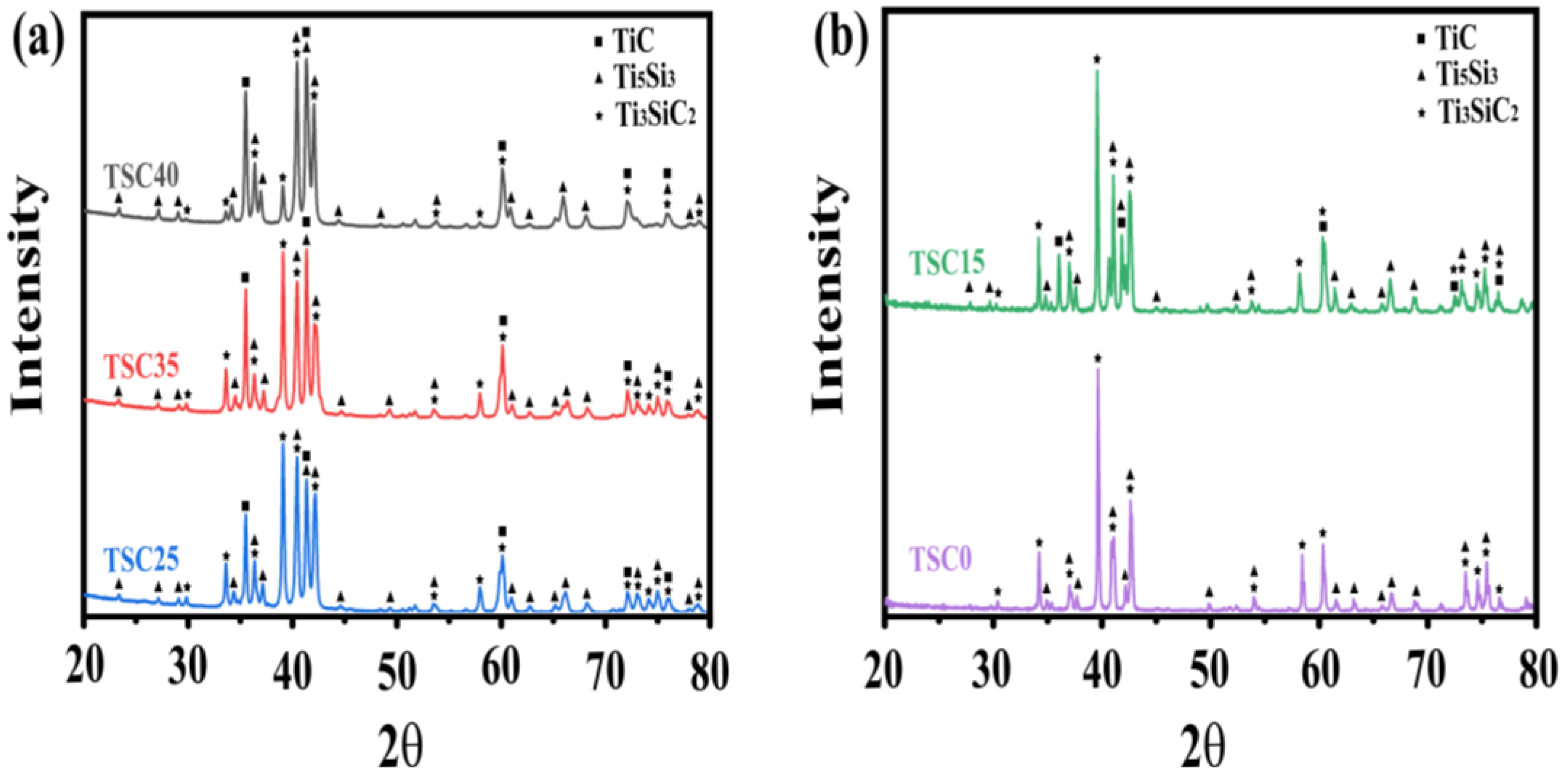
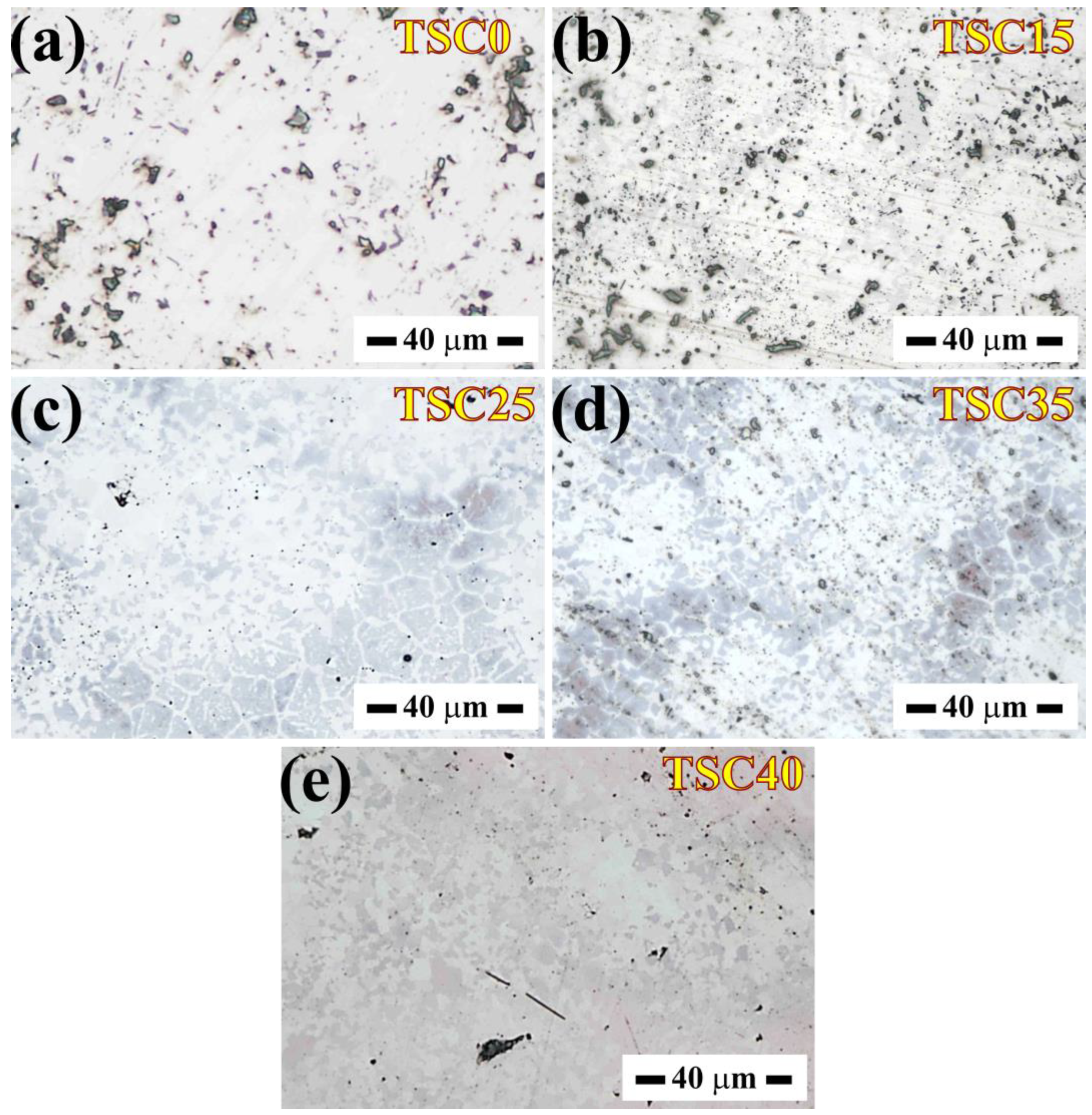
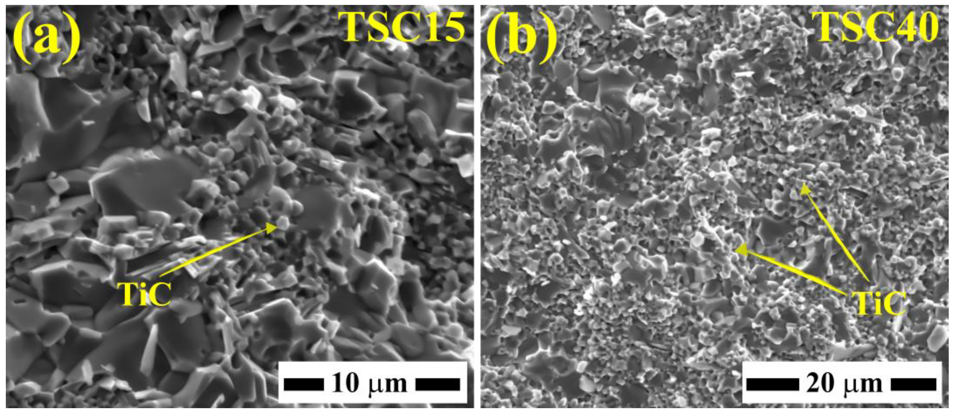
3.1. Microstructures and Phase Analysis of the TSC Composites

The X-ray diffraction (XRD) patterns of the elaborated TSC composites are shown in Figure 1. Except for the TSC0 (0 wt% TiC) composite, the Ti3SiC2, Ti5Si3, and TiC phases were all detected within the other TSC composites. As shown in Table 1, employing a mixture ratio of 3Ti:1SiC:1C led to the successful sintering of the TSC40 sample. The TiC content was lowered to 35 wt.% (TSC35 composite) by extending the soaking time from 20 to 40 min. This allowed additional time for the TiC and Ti5Si3 phases to react with each other, forming more of the Ti3SiC2 phase [17,20,21]. To further diminish the TiC content, an augmentation of the Si content within the reactive starting powders was applied (3Ti:1.2SiC:1C). As a result, TiC and Ti5Si3 were further consumed to form the Ti3SiC2 MAX phase, and the TSC25 composite was successfully manufactured.
Previously [17], we also showed that with the Al addition, TiC could be lowered or eliminated, and TSC15 with TSC0 composites were successfully synthesized. In summary, the TiC content could be easily controlled by controlling the Si and Al contents. Optical micrographs of the polished TSC composites’ surfaces are shown in Figure 2. Since Ti3SiC2 and Ti5Si3 are isostructural, they are visually indistinguishable with an optical microscope. The optical contrast of the Ti3SiC2 and Ti5Si3 phases is nearly the same, which appears as a bright contrast. This indicates that no TiC phase is present in the sample, while the dark regions correspond to pores within the material. With an increase in TiC content, the emergence and expansion of grey-colored phase clusters were observed, which evolved as the composition transitioned from TSC15 to the TSC40 composite.
The scanning electron microscope (SEM) images of the fractured surfaces of the TSC15 and TSC40 composites are shown in Figure 3a and Figure 3b, respectively. The fractured surface of TSC15 is readily distinguishable by flat steps or facets (Figure 3a), a characteristic of cleavage fracture for both the Ti3SiC2 and Ti5Si3 phases [33,34]. EDS analysis revealed those grains to be composed of 53 at. % Ti, 17 at. % of Si, and 30 at. % of C, which is a composition near to that of the MAX phase Ti3SiC2. Nearby, the TiC grains are small and equiaxed, exhibiting a transgranular fracture mode [35]. The TSC40 composite’s fractured surface is marked by a high amount of equiaxed grains, which is expected, since the TiC content is relatively higher (40 wt.%) in this composite (Figure 3b). Note that the carbon signal in EDS might not be entirely reliable; these equiaxed grains are composed mainly of Ti and C (62 at. % Ti, 2 at. % Si, and 36 at. % C).
Titanium carbide’s hardness lies within the range of 23 to 35 GPa [36], making it harder than Ti3SiC2 (4 GPa) [3] and Ti5Si3 (9.7–17.1 GPa) [37]. The hardness of the composites is shown in Table 1, showcasing an increase with increasing TiC content. Thus, the hardness of the composites aligns with the rule of mixtures. The notable increase in hardness can be traced to the significant content and the higher hardness of both the Ti5Si3 and TiC phases.
Ti3SiC2 hardness varies as a function of the load applied during the indentation test due to its anisotropic behavior. T. El-Raghy et al. [38] reported that the hardness is independent of load and grain size at a 100 N indentation load or higher. To mitigate the impact of grain size and anisotropic behavior on hardness and to better highlight the mechanisms of damage tolerance, indentations were performed using a load of 490 N. Notably, the Ti3SiC2 content within the current composites is pivotal in maintaining acceptable toughness. Ti5Si3, in particular, faces a challenge due to its comparatively lower toughness than the other silicides. The increase in toughness in ceramic matrix composites (CMCs) containing MAX phases is primarily due to the damage mechanisms and the energy dissipation during mechanical loading. For instance, the presence of a small amount of the Ti3SiC2 phase in a Ti5Si3/TiC composite showed an increase in toughness from 3.6 ± 0.2 to 5.5 ± 0.4 MPa m1/2 [28].
SEM images depicting the damage mechanisms observed after the indentation tests are shown in Figure 4. It is well documented that the indentation marks in Ti3SiC2 are asymmetric and extend beyond the indentation mark, characterized by the absence of cracks at their corners with different damage mechanisms. Herein, four mechanisms were well identified: (1) delamination, (2) diffuse microcracking (Figure 4b), (3) grain pull-out (Figure 4c), and (4) grain buckling (Figure 4d). These mechanisms dissipate mechanical energy and are responsible for the heightened toughness observed in MAX phases [3,38].
However, it must be noted that the damage tolerance was more pronounced for TSC0, which is not surprising, since the Ti3SiC2 content was higher. According to recent studies [28,39], it can be hypothesized that the fracture toughness of the composites decreases with increasing TiC content. However, it must be noted that even TSC40, which constituted only 13 wt.% of Ti3SiC2, showed some damage tolerance behavior.

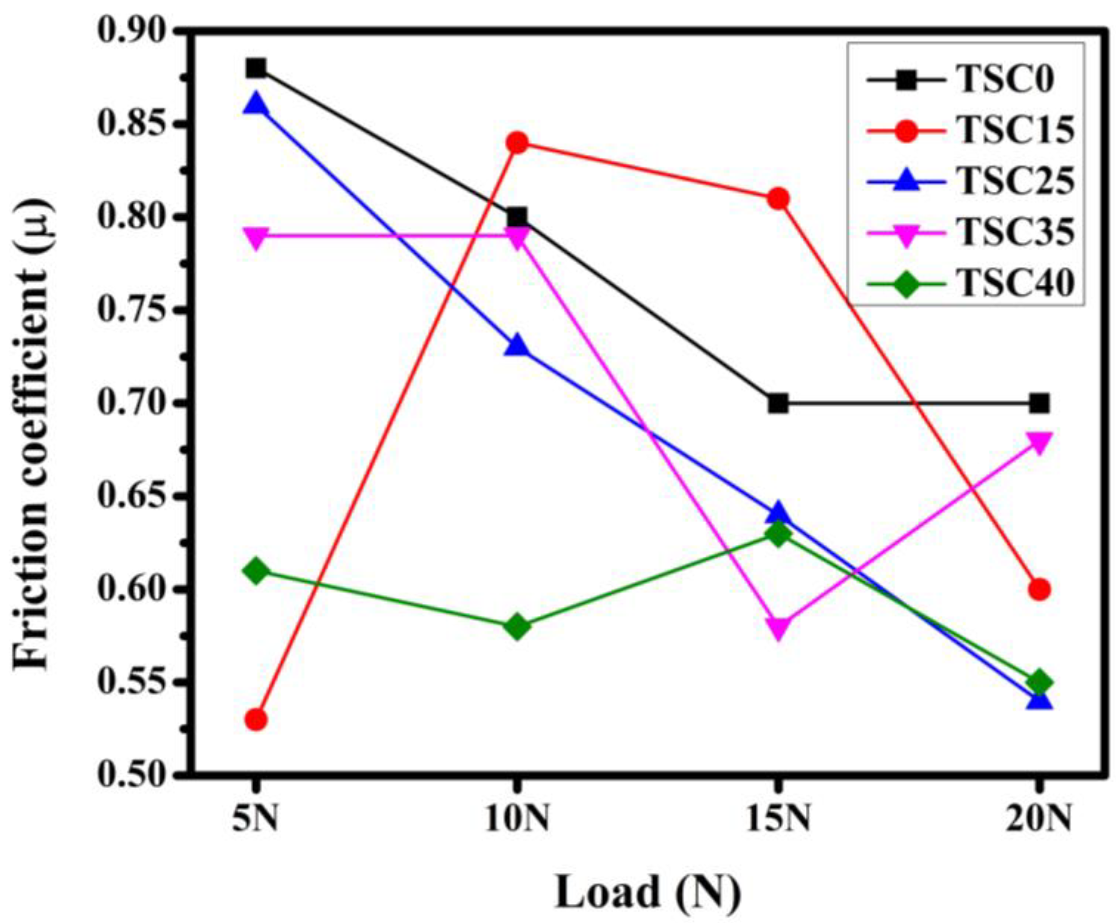
3.2. Wear and Friction Behavior of the TSC Composites

The average values of the friction coefficient are shown in Figure 5. Overall, the TSC0 composite exhibited the highest values under all applied loads [0.7, 0.9], as shown in Table 2. On the contrary, the lowest friction coefficient values were recorded for the TSC40 composite [0.55, 0.61]. However, the TSC25 composite showed a high value at 5 N (0.86), which then decreased progressively with increasing load, ultimately reaching the lowest recorded value (0.54) at a 20 N load.
Figure 6 depicts the specific wear rate average values of the TSC composites sliding against steel under all tested loads. The specific wear rate of the TSC0 composite was notably high, falling within the range of 0.6 to 12 × 10−3 mm3/N·m (Table 2), indicating a dominance of a severe-wear regime. Except for TSC15, all the other composites showed specific wear rate values at least one order of magnitude lower than those of the 0 wt% TiC composite under all applied loads. This wear regime is classified as a mild-wear regime. In the case of the TSC15 composite, there existed a load threshold at which wear transitioned from mild wear at 5 N to a severe-wear regime at 10 N and above.
Interestingly, for the TiC-containing composites, the wear rate decreased as the applied load increased (Figure 6 and Table 2). Following Archard’s rule, material loss is proportional to the applied load. Conversely, the TSC composites sliding against steel did not conform to this rule. Notably, this was more prominent for the TSC15 composite. The specific wear rate initially increased from 2.3 × 10⁻⁵ mm3/N·m under 5 N to 3 × 10⁻⁴ mm3/N·m at 10 N, which corresponds to the transition from a mild- to a severe-wear regime. Upon further increase in the applied load up to 15 N, the specific wear rate slightly decreased, followed by a more significant reduction to 3.5 × 10⁻⁵ mm3/N·m under a 20 N load. In the case of the composites reinforced with 25, 35, and 40 wt.% TiC, the specific wear rate decreased as the applied load increased to attain values lower than two orders of magnitude than those of the 0 wt.% TiC composite (Table 2). The lowest recorded specific wear rate value was 3 × 10⁻⁶ mm3/N·m for the TSC25 composite under a load of 20 N. To sum up, within the same wear regime, for the TiC-containing composites, the specific wear rate decreases when the applied load is higher. The authors suspect that this was because of the adhesive wear of the steel counterpart discussed in the next paragraphs, meaning the higher the load, the more steel is deposited on the worn surfaces, replacing the material lost. Panoramic views of the wear tracks on TSC composites show the difference between the mild- and severe-wear regimes (Figure 7).
In the mild-wear regime, a discernible tribofilm was evident, accompanied by some signs of abrasion. On the other hand, the severe-wear regime, characteristic of low- or no-TiC reinforcement, showed a comparatively chasmic wear track’s width. To further highlight the role of TiC in enhancing the wear resistance of the TSC composites, 2D profiles were obtained of the worn surfaces, as shown in Figure 8. The depth of the worn surface for the 0 wt% TiC composite (TSC0) was 180 μm, whereas it reached a depth as low as 5 to 20 μm in the case of the TiC-containing composite. These 2D profiles showed the remarkable improvement in wear resistance exhibited by these composites.
The SEM analysis of the TSC0 composite’s worn surface (Figure 9a) reveals signs of smeared debris, fractures, and delamination pits. A higher magnification of the inset (labeled “X” in Figure 9a) is shown in Figure 9b. Within the delamination pits, fractured surfaces of the Ti3SiC2/Ti5Si3 composite are seen. This suggests wear by cracking and grain pull-out. A higher magnification of the smeared debris (marked “Y” in Figure 9a) is shown in Figure 9c. EDS point A on these tribolayers indicates the presence of Ti, C, Si, O, and traces of Fe (Table 3). The smeared debris formed adherent tribolayers on the worn surfaces, accompanied by shallow grooves, a sign of third-body abrasive wear. From the above-mentioned observations, the dominant wear mechanism is adhesive wear.
Under the same load of 20N, the worn surface of the TSC25 composite was mostly covered by a tribofilm (Figure 10a). The higher magnification of the tribofilm-free regions shows similar features of the TSC0 composite with less damage, smeared debris, and fractured surfaces (Figure 10b). On the other hand, the TSC40 composite showed discontinuous tribofilms covering an abraded surface; the latter showed grooves parallel to the sliding direction (Figure 10c,d). Under mild-wear behavior, the tribofilms showed the presence of higher amounts of Fe and O compared to the free TiC composite (EDS point B and C, Figure 10, Table 3). Thus, the tribo-oxidative mechanism was observed in these composites.
The wear mechanism of the TiC-reinforced composites under the mild-wear stage showed the deposition of a ferrous layer. In dry sliding of the ceramic materials against the steel counterfaces, the dominant wear generally was identified as tribo-oxidation on the ceramic surface and a combination of severe adhesive and/or abrasive wear on the steel ball [40]. SEM images of the wear scar of the steel ball are shown in Figure 11. The wear scar was circular with signs of abrasive grooves on the steel ball. This confirmed substantial material transfer from the ball to the TSC composite counterface.
The presence of the TiC phase gave a load-bearing capacity to the studied composites. The hard particles acted as hard abrasive particles to the steel ball, promoting iron transfer from the steel ball to the worn surfaces. The formed tribofilm prevented further wear of the composites.

4. Conclusions

The wear and friction behavior of various Ti3SiC2/Ti5Si3-reinforced TiC composites was studied. The main conclusions were drawn as follows:
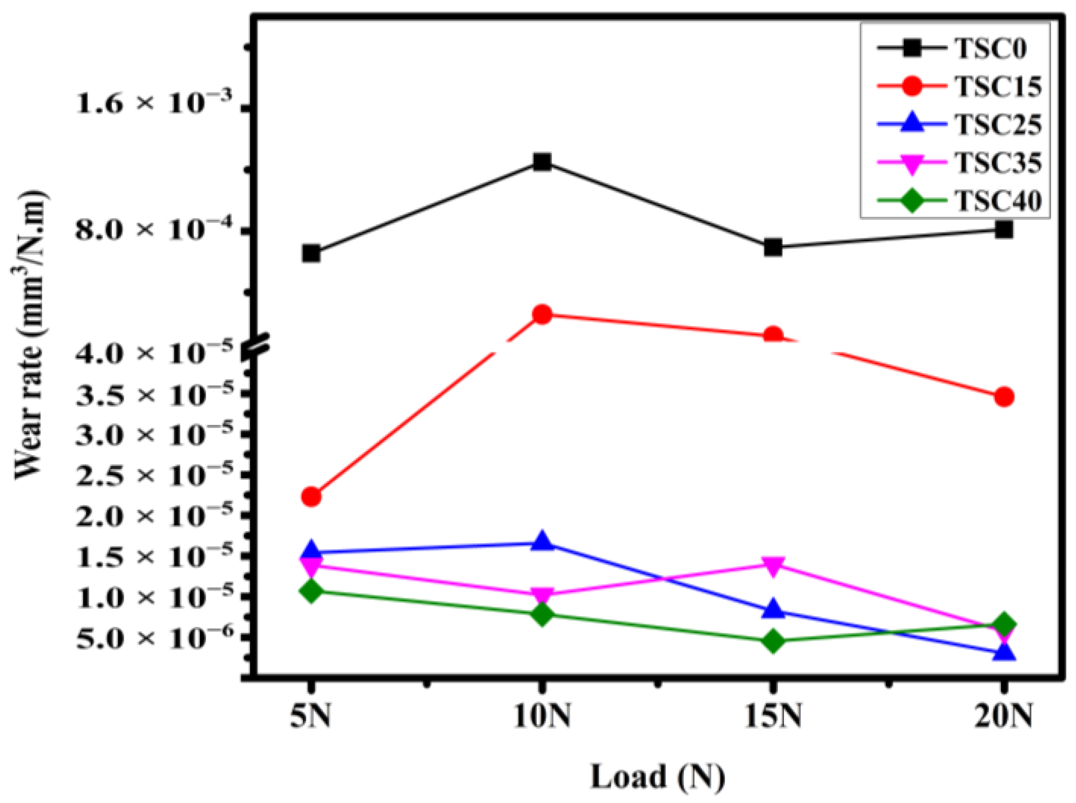
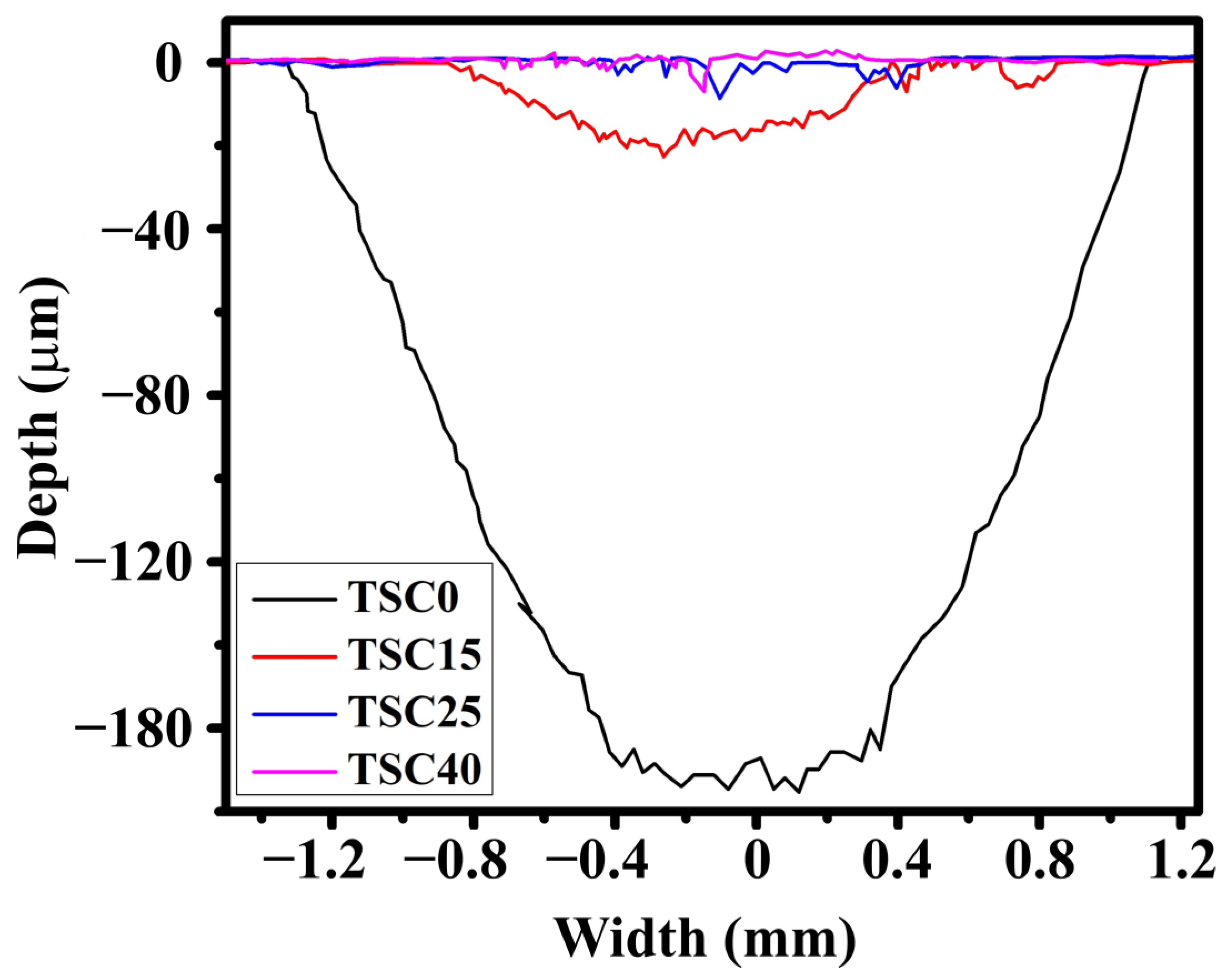
  • Incorporation of the TiC phase provided increases in the hardness and wear resistance of the Ti3SiC2/Ti5Si3 matrix.
  • Two wear regimes were observed in this study, namely, a severe-wear regime and a mild-wear regime:
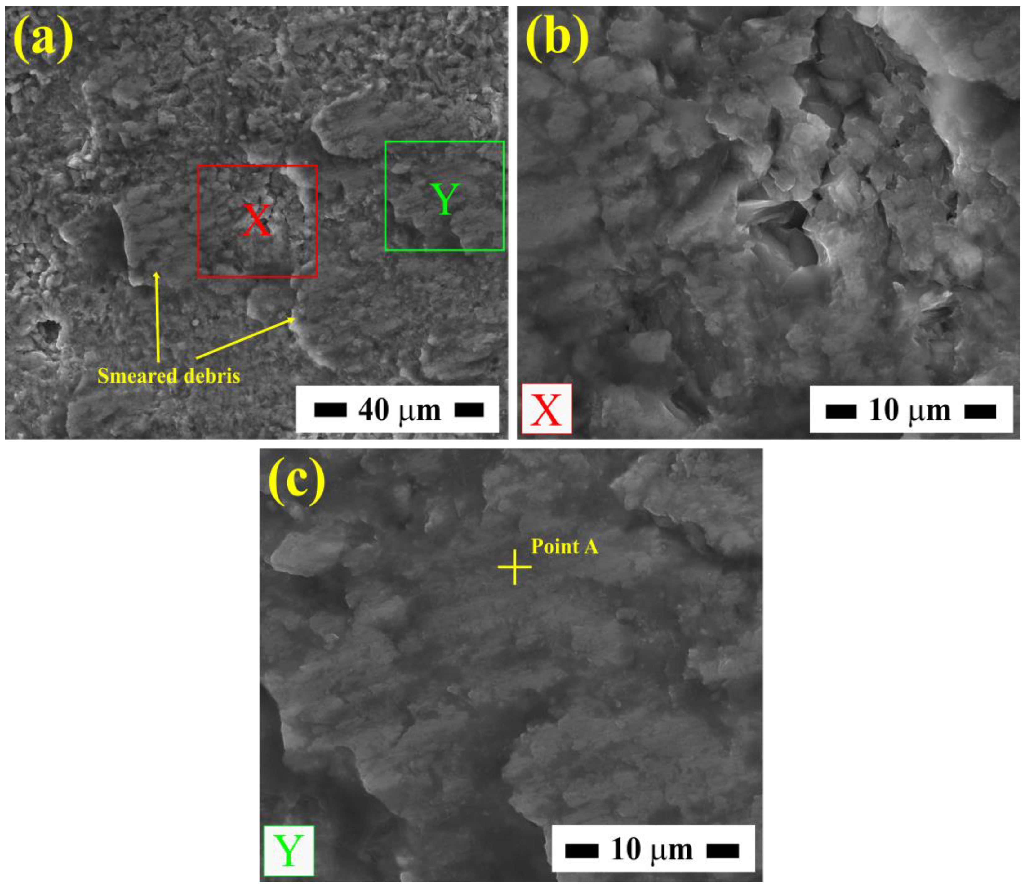
    • The first was characterized by high adhesive wear behavior, tribo-oxidative wear, and minor abrasive wear. The 0wt% TiC composite was dominated by this wear regime under all tested loads.
    • The second wear regime was characterized by the deposition of a ferrous layer composed of Ti, Si, Fe, and O. The tribolayers had an anti-wear behavior with a minor lubrication effect. Within this wear regime, the friction coefficient showed a downward trend with increasing applied load.
  • The composite reinforced with 15 wt.% TiC showed a transition from mild wear under 5 N to severe wear at 10 N and higher.
  • As the TiC content increased to 25 wt.% and higher, only the mild-wear regime was observed.

Author Contributions

A.B. and H.B. conducted the experimental work, analysis, and interpretation of data. Y.H., A.T. and J.-P.E. carried out the sintering of the samples. A.H. and M.S. were responsible for the SEM characterization. N.C. and A.B. were responsible for the dry sliding experiments. M.D., R.B. and M.H. contributed to the conception and organization of this research work, and corrections of the final draft of this manuscript. All authors have read and agreed to the published version of the manuscript.

Funding

This research was funded by Direction Générale de la Recherche Scientifique et du Déveleopement Technologique “DGRSDT” Algeria and Algerian Ministry of Higher Education and Scientific Research under the “Programme National Exceptionnel (PNE)”.

Data Availability Statement

The raw data supporting the conclusions of this article will be made available by the authors on request.

Acknowledgments

The authors wish to express their gratitude to Vedi Dupont at BCRC, Belgium, for his contributions during spark plasma sintering and to Abderrahmane Benamor for helping with the graphical abstract design.

Conflicts of Interest

Author Maharshi Dey was employed by the company UbiQD, Inc. The remaining authors declare that the research was conducted in the absence of any commercial or financial relationships that could be construed as a potential conflict of interest.

References

  1. Munz, D.; Fett, T. Overview and Basic Properties BT. In Ceramics: Mechanical Properties, Failure Behaviour, Materials Selection; Munz, D., Fett, T., Eds.; Springer: Berlin/Heidelberg, Germany, 1999; pp. 1–7. ISBN 978-3-642-58407-7. [Google Scholar]
  2. Karadimas, G.; Salonitis, K. Ceramic Matrix Composites for Aero Engine Applications—A Review. Appl. Sci. 2023, 13, 3017. [Google Scholar] [CrossRef]
  3. Barsoum, M.W. MAX Phases: Properties of Machinable Ternary Carbides and Nitrides; John Wiley & Sons: Hoboken, NJ, USA, 2013; p. 421. [Google Scholar]
  4. Barsoum, M.W.; Radovic, M. Elastic and Mechanical Properties of the MAX Phases. Annu. Rev. Mater. Res. 2011, 41, 195–227. [Google Scholar] [CrossRef]
  5. Sokol, M.; Natu, V.; Kota, S.; Barsoum, M.W. On the Chemical Diversity of the MAX Phases. Trends Chem. 2019, 1, 210–223. [Google Scholar] [CrossRef]
  6. Luo, Y.; Pan, W.; Li, S.; Wang, R.; Li, J. Fabrication of Al2O3–Ti3SiC2 Composites and Mechanical Properties Evaluation. Mater. Lett. 2003, 57, 2509–2514. [Google Scholar] [CrossRef]
  7. Lou, Z.; Li, Y.; Zou, Q.; Luo, W.; Gu, H.; Li, Z.; Luo, Y. In-Situ Fabrication and Characterization of TiC Matrix Composite Reinforced by SiC and Ti3SiC2. Ceram. Int. 2023, 49, 20849–20859. [Google Scholar] [CrossRef]
  8. Fan, X.; Yin, X. Microstructure and Properties of Carbon Fiber Reinforced SiC Matrix Composites Containing Ti3SiC2. Adv. Eng. Mater. 2014, 16, 670–683. [Google Scholar] [CrossRef]
  9. Yan, H.; Liu, K.; Zhang, P.; Zhao, J.; Qin, Y.; Lu, Q.; Yu, Z. Fabrication and Tribological Behaviors of Ti3SiC2/Ti5Si3/TiC/Ni-Based Composite Coatings by Laser Cladding for Self-Lubricating Applications. Opt. Laser Technol. 2020, 126, 106077. [Google Scholar] [CrossRef]
  10. Dey, M.; Fuka, M.; AlAnazi, F.; Gupta, S. Synthesis and Characterization of Novel Ni-Ti3SiC2 Composites. In Proceedings of the 42nd International Conference on Advanced Ceramics and Composites: Ceramic Engineering and Science Proceedings; John Wiley & Sons: Hoboken, NJ, USA, 2019; pp. 105–116. ISBN 9781119543381. [Google Scholar]
  11. Chiker, N.; Benamor, A.; Hadji, Y.; Haddad, A.; Hakem, M.; Azzaz, M.; Sahraoui, T.; Hadji, M. Microstructure and Tribological Behavior of In Situ TiC-Ni(Si,Ti) Composites Elaborated from Ni and Ti3SiC2 Powders. J. Mater. Eng. Perform. 2020, 29, 1995–2005. [Google Scholar] [CrossRef]
  12. Zhang, F.; Zhao, L.; Yan, S.; He, J.; Yin, F. Microstructure and Mechanical Properties of Plasma Sprayed TiC/Ti5Si3/Ti3SiC2 Composite Coatings with Al Additions. Ceram. Int. 2020, 46, 16298–16309. [Google Scholar] [CrossRef]
  13. Zhang, F.; Zhao, L.; Yu, G.; Chen, J.; Yan, S.; He, J.; Yin, F. Effect of Annealing Temperature on Microstructure and Mechanical Properties of Plasma Sprayed TiC-Ti5Si3-Ti3SiC2 Composite Coatings. Surf. Coat. Technol. 2021, 422, 127581. [Google Scholar] [CrossRef]
  14. Li, C.; Zhou, Z.; Hu, L.; He, J.; Zheng, G.; Zhao, H.; Dong, Y.; Yang, Y.; Qin, Y.; Yin, F. Fabrication of Plasma-Sprayed TiC-Ti5Si3-Ti3SiC2 Composite Coatings from the Annealed Ti/SiC Powders. Surf. Coat. Technol. 2021, 417, 127227. [Google Scholar] [CrossRef]
  15. Li, Y.; Bi, Y.; Xing, Y.; Li, B.; He, J.; Qin, Y.; Zhao, H. Plasma Sprayed TiC–Ti5Si3–Ti3SiC2 Composite Coatings from Ti–SiC-Graphite Powders with Different SiC Particle Size. Ceram. Int. 2023, 49, 36763–36773. [Google Scholar] [CrossRef]
  16. Li, C.; Zhang, F.; He, J.; Yin, F. Preparation and Properties of Reactive Plasma Sprayed TiC–Ti5Si3–Ti3SiC2/Al Coatings from Ti–Si–C–Al Mixed Powders. Mater. Chem. Phys. 2021, 269, 124772. [Google Scholar] [CrossRef]
  17. Benamor, A.; Hadji, Y.; Chiker, N.; Haddad, A.; Bendiba, G.; Labaiz, M.; Hakem, M.; Tricoteaux, A.; Nivot, C.; Erauw, J.-P.; et al. Spark Plasma Sintering and Tribological Behavior of Ti3SiC2–Ti5Si3–TiC Composites. Ceram. Int. 2019, 45, 21781–21792. [Google Scholar] [CrossRef]
  18. Magnus, C.; Cooper, D.; Ma, L.; Rainforth, W.M. Microstructures and Intrinsic Lubricity of in Situ Ti3SiC2–TiSi2–TiC MAX Phase Composite Fabricated by Reactive Spark Plasma Sintering (SPS). Wear 2020, 448–449, 203169. [Google Scholar] [CrossRef]
  19. Magnus, C.; Sharp, J.; Rainforth, W.M. The Lubricating Properties of Spark Plasma Sintered (SPS) Ti3SiC2 MAX Phase Compound and Composite. Tribol. Trans. 2020, 63, 38–51. [Google Scholar] [CrossRef]
  20. Hadji, Y.; Benamor, A.; Chiker, N.; Haddad, A.; Tala-Ighil, N.; Erauw, J.; Dupont, V.; Tricoteaux, A.; Nivot, C.; Thuault, A.; et al. Tribological behavior of composites fabricated by reactive SPS sintering in Ti-Si-C system. Int. J. Appl. Ceram. Technol. 2019, 17, 695–706. [Google Scholar] [CrossRef]
  21. Ghosh, N.C.; Harimkar, S.P. Phase Analysis and Wear Behavior of In-Situ Spark Plasma Sintered Ti3SiC2. Ceram. Int. 2013, 39, 6777–6786. [Google Scholar] [CrossRef]
  22. Usha Kiran, N.; Das, P.; Chatterjee, S.; Besra, L. Effect of ‘Ti’ Particle Size in the Synthesis of Highly Pure Ti3SiC2 MAX Phase. Nano-Struct. Nano-Objects 2022, 30, 100849. [Google Scholar] [CrossRef]
  23. Tabares, E.; Jiménez-Morales, A.; Tsipas, S.A. Study of the Synthesis of MAX Phase Ti3SiC2 Powders by Pressureless Sintering. Boletín Soc. Española Cerámica Vidr. 2021, 60, 41–52. [Google Scholar] [CrossRef]
  24. Zhang, Z.F.; Sun, Z.M.; Hashimoto, H.; Abe, T. Effects of Sintering Temperature and Si Content on the Purity of Ti3SiC2 Synthesized from Ti/Si/TiC Powders. J. Alloys Compd. 2003, 352, 283–289. [Google Scholar] [CrossRef]
  25. Emmerlich, J.; Music, D.; Eklund, P.; Wilhelmsson, O.; Jansson, U.; Schneider, J.M.; Högberg, H.; Hultman, L. Thermal Stability of Ti3SiC2 Thin Films. Acta Mater. 2007, 55, 1479–1488. [Google Scholar] [CrossRef]
  26. Mitra, R. Microstructure and Mechanical Behavior of Reaction Hot-Pressed Titanium Silicide and Titanium Silicide-Based Alloys and Composites. Metall. Mater. Trans. A 1998, 29, 1629–1641. [Google Scholar] [CrossRef]
  27. Frommeyer, G.; Rosenkranz, R. Structures and Properties of the Refractory Silicides Ti5Si3 and TiSi2 and Ti-Si-(Al) Eutectic Alloys BT. In Metallic Materials with High Structural Efficiency; Senkov, O.N., Miracle, D.B., Firstov, S.A., Eds.; Springer: Dordrecht, The Netherlands, 2004; pp. 287–308. [Google Scholar]
  28. Wang, L.; Jiang, W.; Chen, L.; Bai, G. Microstructure of Ti5Si3–TiC–Ti3SiC2 and Ti5Si3–TiC Nanocomposites in Situ Synthesized by Spark Plasma Sintering. J. Mater. Res. 2004, 19, 3004–3008. [Google Scholar] [CrossRef]
  29. Guedouar, B.; Hadji, Y.; Benamor, A.; Chiker, N.; Haddad, A.; Tricoteaux, A.; Erauw, J.-P.; Dupont, V.; Hadj-Larbi, F.; Soualili, M.A.; et al. Oxidation Behavior of Al-Doped Ti3SiC2-20 Wt.%Ti5Si3 Composite. Ceram. Int. 2021, 47, 33622–33631. [Google Scholar] [CrossRef]
  30. Zhang, W.; Yamashita, S.; Kita, H. Effect of Counterbody on Tribological Properties of B4C–SiC Composite Ceramics. Wear 2020, 458–459, 203418. [Google Scholar] [CrossRef]
  31. Sharma, S.K.; Manoj Kumar, B.V.; Kim, Y.-W. Tribology of WC Reinforced SiC Ceramics: Influence of Counterbody. Friction 2019, 7, 129–142. [Google Scholar] [CrossRef]
  32. Gupta, Y.; Manoj Kumar, B.V. ZrB2–SiC Composites for Sliding Wear Contacts: Influence of SiC Content and Counterbody. Ceram. Int. 2022, 48, 14560–14567. [Google Scholar] [CrossRef]
  33. Zhang, Z.F.; Sun, Z.M. Shear Fracture Behavior of Ti3SiC2 Induced by Compression at Temperatures below 1000 °C. Mater. Sci. Eng. A 2005, 408, 64–71. [Google Scholar] [CrossRef]
  34. Zhang, L.; Wu, J. Ti5Si3 and Ti5Si3-Based Alloys: Alloyingbehavior, Microstructure and Mechanical Property Evaluation. Acta Mater. 1998, 46, 3535–3546. [Google Scholar] [CrossRef]
  35. Yang, J.; Pan, L.; Gu, W.; Qiu, T.; Zhang, Y.; Zhu, S. Microstructure and Mechanical Properties of in Situ Synthesized (TiB2+TiC)/Ti3SiC2 Composites. Ceram. Int. 2012, 38, 649–655. [Google Scholar] [CrossRef]
  36. Kumashiro, Y.; Itoh, A.; Kinoshita, T.; Sobajima, M. The Micro-Vickers Hardness of TiC Single Crystals up to 1500 °C. J. Mater. Sci. 1977, 12, 595–601. [Google Scholar] [CrossRef]
  37. Rosenkranz, R.; Frommeyer, G.; Smarsly, W. Microstructures and Properties of High Melting Point Intermetallic Ti5Si3 and Ti5i2 Compounds. In High Temperature Aluminides and Intermetallics; Whang, S.H., Pope, D.P., Liu, C.T., Eds.; Elsevier: Oxford, UK, 1992; pp. 288–294. ISBN 978-1-85166-822-9. [Google Scholar]
  38. El-Raghy, T.; Zavaliangos, A.; Barsoum, M.W.; Kalidindi, S.R. Damage Mechanisms around Hardness Indentations in Ti3SiC2. J. Am. Ceram. Soc. 1997, 80, 513–516. [Google Scholar] [CrossRef]
  39. Li, J.; Jiang, D.; Tan, S. Microstructure and Mechanical Properties of in Situ Produced Ti5Si3/TiC Nanocomposites. J. Eur. Ceram. Soc. 2002, 22, 551–558. [Google Scholar] [CrossRef]
  40. Chiker, N.; Benamor, A.; Haddad, A.; Hadji, Y.; Hakem, M.; Badji, R.; Labaiz, M.; Azzaz, M.; Hadji, M. Pressureless Sintering and Tribological Properties of In-Situ TiC-Ni3(Al,Ti)/Ni(Al,Ti) Composites. Int. J. Refract. Met. Hard Mater. 2021, 98, 105559. [Google Scholar] [CrossRef]
Figure 1. XRD patterns of the spark-plasma-intered composites (a) without Al addition (TSC25, TSC35, and TSC40) and (b) with 0.2 at.% of Al in the starting powder (TSC15 and TSC0).
Lubricants 12 00368 g001
Figure 2. Optical micrographs of the composites’ polished surfaces. (a) 0 wt.% TiC, (b) 15 wt.% TiC, (c) 25 wt.% TiC, (d) 35 wt.% TiC, and (e) 40 wt.% TiC in Ti3SiC2-Ti5Si3-TiC composites.
Lubricants 12 00368 g002
Figure 3. SEM micrographs—secondary electron (SE) mode—showing fractured surfaces of (a) TSC15 and (b) TSC40 composites.
Lubricants 12 00368 g003
Figure 4. SEM micrographs (SE mode) showing different damage tolerance mechanisms: (a) diffuse microcracking, (b) delamination, (c) grain pull-out, and (d) buckling. Vickers indentation marks at 490N load on TSC0 (a,b) and TSC15 (c,d) composites.
Lubricants 12 00368 g004
Figure 5. Mean friction coefficient values versus load applied.
Lubricants 12 00368 g005
Figure 6. Specific wear rate values versus load applied.
Lubricants 12 00368 g006
Figure 7. Optical micrographs’ wear tracks of the (a) TSC0 and (b) TSC25 composites under 20 N load.
Lubricants 12 00368 g007
Figure 8. Wear tracks’ 2D profiles of the different composites under 20 N load.
Lubricants 12 00368 g008
Figure 9. SEM (SE mode) images of of: (a) Worn surface of TSC0 under 5 N load, (b) SE image of the area marked as “X” in (a), (c) SE image of the area marked as “Y” in (a).
Lubricants 12 00368 g009
Figure 10. SEM (SE mode) of the (a,b) TSC25 and (c,d) TSC40 worn surfaces under 5 N load.
Lubricants 12 00368 g010
Figure 11. SEM (SE mode) image of: (a) steel ball wear scar, (b) Higher magnification SE image of (a), showing steel ball wear.
Lubricants 12 00368 g011
Table 1. Summary of the spark plasma sintering details, phase compositions, and Vickers hardness values for all TSC composites.
Sample DesignationPowder RatiosPhase Composition by Weight (%)Hardness (GPa)Sintering Time (min)
Ti3SiC2Ti5Si3TiC
TSC403Ti:1SiC:1C13.3047.7939.189.76 ± 0.820
TSC353Ti:1SiC:1C39.0937.2035.498.11 ± 0.740
TSC253Ti:1.2SiC:0.8C50.8225.6223.567.88 ± 0.420
TSC153Ti:1SiC:1C:0.2Al58.1728.0313.807.22 ± 0.120
TSC03Ti:1.2SiC:0.8C:0.2Al80.2619.7405.24 ± 0.520
Table 2. Average friction coefficient and specific wear rate values of the different composites under all applied normal loads.
Loads
Sample5 N10 N15 N20 N
TSC0Μ0.880.80.70.7
SWR (mm3/N·m) × 10−46.512.56.98.1
Ball’s SWR (mm3/N·m) × 10−40.110.060.120.1
TSC15Μ0.530.840.810.6
SWR (mm3/N·m) × 10−40.22.61.20.34
Ball’s SWR (mm3/N·m) × 10−40.090.260.230.17
TSC25Μ0.860.730.640.54
SWR (mm3/N·m) × 10−40.150.160.080.03
Ball’s SWR (mm3/N·m) × 10−40.020.070.090.07
TSC35Μ0.790.790.580.68
SWR (mm3/N·m) × 10−40.140.100.140.05
Ball’s SWR (mm3/N·m) ×10−40.010.0140.040.05
TSC40Μ0.610.580.630.55
SWR (mm3/N·m) × 10−40.100.070.040.06
Ball’s SWR (mm3/N·m) × 10−40.130.060.050.08
Table 3. Energy dispersive X-ray spectroscopy points in atomic percent (marked in Figure 9 and Figure 10).
PointTiSiCOFeNominal Elemental Comp.
A66 ± 0.19 ± 122 ± 0.93 ± 0.30.3 ± 0.2Ti66CxSi9O3Fe0.3
B39 ± 0.46 ± 0.320 ± 123 ± 1.312 ± 0.5Ti39CxSi6O23Fe12
C27 ± 0.054 ± 1.220 ± 0.823 ± 226 ± 2Ti27Fe26O23CxSi4
Disclaimer/Publisher’s Note: The statements, opinions and data contained in all publications are solely those of the individual author(s) and contributor(s) and not of MDPI and/or the editor(s). MDPI and/or the editor(s) disclaim responsibility for any injury to people or property resulting from any ideas, methods, instructions or products referred to in the content.

