Abstract
Accurately predicting the performance of gas foil bearings (GFBs) is important. This paper presents a new fully coupled elastic–aerodynamic model for analyzing the static performance of gas foil journal bearings (GFJBs). The gas compressible lubrication model was solved in MATLAB to obtain the gas pressure. The foil structure deformation was solved in COMSOL by considering the Coulomb friction and allowing the contact surfaces to be separated from each other. Under given load and rotational speed conditions, the calculated minimum gas film thickness and attitude angle match well with the literature data, validating the accuracy of the developed model. Based on the model developed, a comprehensive and systematic analysis of the effects of the structural parameters on the static performance was performed. The results showed that as the bump height, top foil thickness, and bump foil thickness increased, the load capacity could be improved to different degrees. The bump foil thickness had the greatest effect on the load capacity. These results provide theoretical guidance for the structural design and practical applications of GFJBs.
1. Introduction
Gas foil bearings (GFBs) have advantages such as high motion accuracy, reduced friction, minimal noise, and long service life and are increasingly widely used in oil-free compressors and air-cycle machines (ACMs) [1,2]. Bump-type GFBs, which are the first generation of GFBs, are usually composed of a top foil and a bump foil. The top foil provides a smooth contact surface, whereas the bump foil provides stiffness and damping. Utilizing gas as the lubricant, the journal is supported by the gas dynamic pressure effect generated in the wedge-shaped gap [3]. The presence of the foil structure significantly improves its adaptability to the environment. However, the relative complexity and flexibility of the foil structure increase the difficulty of theoretical modeling [4].
Walowit et al. [5] focused only on the friction between the sleeve and bump foil and derived a stiffness calculation formula. Heshmat et al. [6] ignored the top foil deformation and simplified the bump foil into a single spring to introduce a simple elastic foundation model (SEFM). Iordanoff [7] and Swanson [8] independently introduced a simplified single-foil model for characterizing the stiffness properties of the bump foil. However, these models only consider a single bump foil. For an accurate prediction of the GFB’s performance, the friction of the two contact pairs and the interaction between the bump foils are also important. The top foil offers a smooth interface for contact between the journal and bearing; its deformation directly affects the gas film. Therefore, when solving the coupling between the structural and fluid domains, the top foil deformation must also be considered.
Lez et al. [9] considered a continuous bump foil as a system with multiple degrees of freedom considering the friction force and deduced a stiffness formula using an analytical method. Lez et al. [9] assumed that these two contacts were inseparable. Gu et al. adopted a contact model to consider the friction and separation behavior. It was found that the model in which the top and bump foils could be separated was more in line with engineering practice [10,11]. Arghir [12] and Nielsen [13] achieved the separation between the top foil and the bump foil, enabling the solution to structural problems involving contact friction and separation. Gad and Kaneko [14] also introduced more realistic boundary conditions at both ends of a bump foil, considering the possibility of contact separation between the sleeve and bump foil. Subsequently, the bearing performance was predicted by combining the structural and fluid flow models. Some scholars conducted research on the deformation of the top foil, established foil-bearing models, and unveiled the significance of top foil deformation in the performance analysis of GFBs [15,16,17]. Carpino and Talmage [18] proposed a fully coupled finite element formula for a GFB by considering the structural and fluid coupling effects, and the equations were solved by adopting the Newton–Raphson method. Some scholars considered the heat transfer in the bearing-journal system and established a thermohydrodynamic (THD) model, thereby further enhancing prediction accuracy [19,20,21,22,23].
Scholars have proposed a variety of mathematical models for GFJB. However, the bump foil is typically simplified as a spring. The accuracy still needs to be improved, and an accurate analysis of the performance of the GFJB remains challenging. An accurate GFJB model should consider the elasticity of the bump foil, interactions among the bump foils, local top foil deformation, and friction between the contact interfaces. Commercial finite element software can model complex foil structures in detail and has attracted increasing attention.
Hassan and Bonello [24] adopted a finite element method based on the ANSYS Mechanical software 15.0 to study the dynamic performance of bump foil structures for the first time. Through a performance analysis based on ANSYS Fluent, Chakraborty et al. [25] found that the gas film thickness, system stiffness, load capacity, and lift-off speed were all affected by the thickness of the bump and top foils. Zywica [26] and Fatu [27] established the foil structure model using the finite element method in ABAQUS and conducted research on the performance.
Although the use of commercial software for calculations is accurate, the calculation time is relatively long. The use of self-programming requires a certain simplification of the model, which results in decreased accuracy. Therefore, it is necessary to construct a new model to solve complete aeroelastic coupling problems by considering the advantages of both.
The structural parameters, foil material, and assembly clearance significantly affect bearing performance. Scholars have also conducted many studies on the performance of GFJBs, including the effects of rotation speed and external load [28,29,30], bearing geometric parameters [31,32,33,34], waviness [35], and misalignment [36] on the static stiffness and performance, including attitude angle, pressure distribution, and load capacity. Although scholars have significantly contributed to the analysis of the performance of GFJBs, there is still a lack of systematic studies on the effects of foil structural parameters to provide theoretical guidance for the structural design of GFJBs.
In this study, considering the complex shape and interaction of the foil structure of a bump-type GFJB, a new modeling method for GFJB is proposed. A simulation approach with the advantages of both self-programming and commercial software was employed. A finite element model was established to consider the foil structure in detail using the COMSOL software 5.5. A gas compressible lubrication model was established using MATLAB R2019a. Foil deformation and gas pressure were fully coupled using MATLAB and COMSOL co-simulations. Based on the developed model, the effects of different structural parameters and working conditions on the static performance of GFJBs were comprehensively and systematically analyzed, which can offer theoretical guidance for the structural design and practical application of GFJBs.
2. Theoretical Model
2.1. Lubrication Model
A bump-type GFJB and its foil structure are shown in Figure 1. The axial direction of the bearing is designated as , the circumferential direction as , and the negative y-axis direction serves as the origin for , which increases clockwise from 0 to 360 degrees. To facilitate the calculation, the Reynolds equation is made dimensionless and expressed as follows:
The dimensionless factors are defined as follows:
where is the ambient pressure, is the bearing radius, is the radial clearance, is the angular velocity of the journal, is the air viscosity, is the dimensionless pressure, and is the dimensionless film thickness.
The dimensionless gas film thickness is calculated as follows:
where , , is the eccentricity, is attitude angle, and is the top foil deformation.
The boundary conditions are expressed as follows:
By integrating the gas film pressure, the load capacity , radial component , and tangential component are calculated as follows:
The torque direction is positive when it is opposite to the rotational direction of the journal, and the circumferential friction torque acting on the journal surface is determined as follows:

Figure 1.
Illustrative diagram of GFJB: (a) bump-type GFJB; (b) foil structure.
2.2. Contact Model
The contact phenomenon significantly affects the stiffness and damping of GFJBs; thus, it is important to develop an accurate contact model. The finite element analysis software COMSOL, which can model and analyze complex contact phenomena, was used to analyze the deformation behavior of the GFJBs under different load distributions.
COMSOL performs deformation analyses in Solid Mechanics using Lagrange’s formula. The original position of the material particle is defined as , and the new position is . Then, the deformation gradient can be represented by
where
According to the polar decomposition theorem, can be written as follows:
where is the pure rotation matrix and is the right extension tensor. Equation (11) can also be written as follows:
The three eigenvalues of are , , and ; their corresponding eigenvectors are the three orthogonal directions of the material coordinate system. Elongation can be defined as the ratio of the current length to the original length, which can be expressed as follows:
To obtain the zero-based deformation of the top foil, we subtract the equivalent tensor from to obtain the Green–Lagrange strain tensor , defined as follows:
The boundary conditions must be defined in Solid Mechanics. The sleeve was regarded as a rigid body, and one end of the bump foil and the top foil were welded to the sleeve, which was fixed. The static Coulomb friction law is adopted for the contact model. In the Coulomb friction law, the magnitudes of static friction and sliding friction are the same. The friction force is represented by
where is the relative velocity and is the contact force.
In the model, the journal and the sleeve are set as rigid bodies. Two contact pairs are defined in the contact model. The upper surface of the sleeve and the lower surface of the bump foil are set as contact pairs, as are the upper surface of the bump foil and the lower surface of the top foil. Each contact pair includes a source boundary and a destination boundary. The boundary, which is relatively rigid or concave, is considered to be the source boundary. For the contact pair composed of the sleeve and bump foil, the source boundary is the upper surface of the sleeve. Similarly, for the contact pair composed of the bump foil and the top foil, the source boundary is the lower surface of the top foil. Two boundaries of a contact pair are allowed to be separated from each other. There are two alternative calculation methods, including the penalty function method and the augmented Lagrange method. The penalty function method is less accurate but more robust. The augmented Lagrange method has higher precision but also a higher calculation cost. In our study, the penalty function method is adopted in the contact model. To achieve faster and more stable convergence, a ‘spring’ is added between the contact surfaces. There is a global parameter for which the slope varies from 0 to 1 in the Study-Steady-Assisted scan. Thus, the spring constant can be expressed as follows:
where the peak value of the spring stiffness is .
2.3. Numerical Solution
The Reynolds equation was solved numerically using the finite volume method (FVM), as shown in Figure 2.

Figure 2.
Finite volume discretization with details of a control volume.
The flow rates per unit length in directions and are expressed as follows:
The flow rates through the four faces of the control volume are expressed as follows:
Based on the law of flow conservation, for a control volume, the inflow is equal to the outflow, which can be expressed as follows:
The relationship between a node and its surrounding nodes can be expressed as follows:
The iterative formula for load balance was derived using a Taylor binary first-order expansion. Given an initial eccentricity , the gas film pressure was calculated based on elastic–aerodynamic coupling, and the load capacity was then calculated. The difference between the load capacity and load in the two directions is expressed as follows:
Similarly, the difference in the values of , and , under the eccentricity and were obtained. The Taylor first-order expansions of and at the eccentricity are expressed as follows:
The updated eccentricity is represented as follows:
For a given load, the eccentricity was updated several times until the gas film load capacity and load were balanced; subsequently, a stable eccentricity was obtained.
Figure 3 shows the calculation diagram for the static performance prediction of the GFJBs. The foil structure deformation was calculated in COMSOL, and the solution of the gas compressible lubrication model was realized using MATLAB code. The data exchange between COMSOL and MATLAB was realized using COMSOL’s LiveLink for the MATLAB function [37]. The gas film pressure was calculated using MATLAB and imported into COMSOL software, and top foil deformation was calculated using COMSOL and measured in MATLAB using an interpolation function. After several data transfers between MATLAB and COMSOL, full aeroelastic coupling was achieved. Load balance was realized using code written in MATLAB. It should be noted that the coordinate systems and mesh divisions of COMSOL and MATLAB are independent of each other.
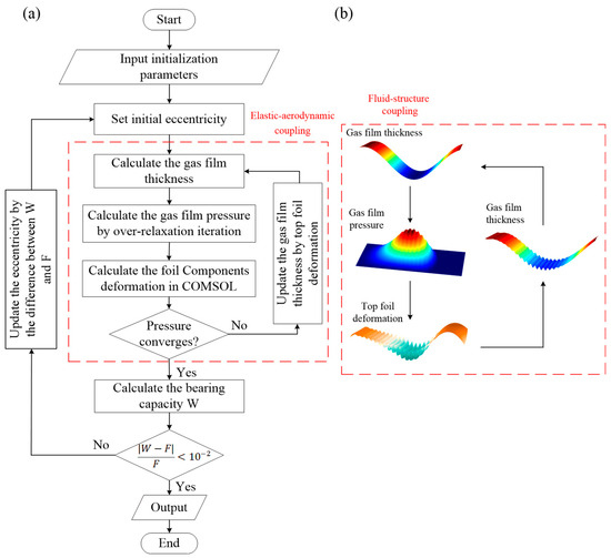
Figure 3.
Schematic diagram of the calculation process: (a) the static performance calculations of GFJBs; (b) the coupling of fluid and structure.
3. Results and Discussion
3.1. Static Stiffness Analysis
As listed in Table 1, the basic parameters of the bump-type GFJB are selected to be the same as those in [38].

Table 1.
Basic parameters of the GFJB.
As illustrated in Figure 4a,b, the static stiffness of the foil structure composed of ten bumps was investigated. For modeling convenience, the foil structure was spread in the circumferential direction. To reduce the computation time, a 2D mesh was generated using COMSOL, as shown in Figure 4c. To reflect the real operating conditions of the GFJBs, the boundary conditions were set as follows: the sleeve was fixed, the left ends of the bump foil and top foil were fixed, and the rest were free. Table 2 shows the influence of mesh density on computation time and accuracy. When the mesh was finer, the computation time was longer, and the relative error was smaller. In our study, Mesh 3, which had the highest accuracy, was chosen.
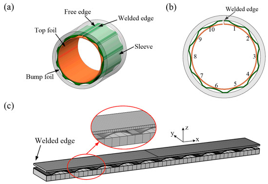
Figure 4.
Structure diagram of a bump-type GFJB composed of ten bumps: (a) axonometric view; (b) frontal view; and (c) mesh generation in COMSOL.

Table 2.
Influence of mesh density on computation time and accuracy.
To confirm the validity of the developed model, the results were compared with those reported in a previous study [9], as shown in Figure 5. Two load distributions were considered: (a) uniform and (b) increasing–decreasing; the equivalent pressure in both cases was 0.2 MPa. The friction coefficient was set to 0.1. Bump no. 1 was the fixed end. The ordinate is the vertical displacement of the upper surface of the top foil corresponding to the highest point of the bump foil. Under the two load distributions, the simulation results of our model closely aligned with those in reference [9], thus validating the precision of our model.
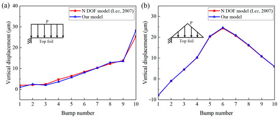
Figure 5.
Top foil displacement under two load distributions: (a) uniform; (b) increasing–decreasing [9].
During the operation of the GFJBs, the increasing–decreasing load was more consistent with the actual operating conditions. Thus, an increasing–decreasing load distribution was chosen to study the effects of the foil parameters and friction coefficient on the static stiffness.
3.1.1. Effect of Top Foil Thickness on Static Stiffness
Figure 6 illustrates the effect of the top foil thickness on the vertical displacement distribution and stiffness curves of the foil structure. The other foil parameters remained unchanged, and the top foil thicknesses were 0.075, 0.102, 0.15, and 0.3 mm.

Figure 6.
Effect of top foil thickness on (a) vertical displacement of top foil and (b) bump foil stiffness of the bump-type foil structure.
As shown in Figure 6, the vertical displacement of the top foil shows oscillation, and the closer the position is to the middle, the more evident the oscillation. The bump foil provides certain support; therefore, the vertical displacement of the top foil is small at the position where the bump and top foils are in contact, whereas the vertical displacement between the two bumps is relatively large. As the top foil thickness decreased, the top foil stiffness decreased, whereas the bump foil stiffness was not affected.
3.1.2. Effect of Bump Foil Thickness on Static Stiffness
Figure 7 illustrates the effect of the bump foil thickness on the vertical displacement distribution and stiffness curves of the foil structure. Other foil parameters remained unchanged, and bump foil thicknesses with values of 0.05, 0.102, 0.15, and 0.3 mm were studied.
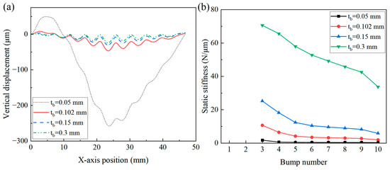
Figure 7.
Effect of bump foil thickness on (a) vertical displacement of top foil and (b) bump foil stiffness of the bump-type foil structure.
As illustrated in Figure 7, as the bump foil thickness increased, the vertical displacement of the top foil decreased, and the bump foil stiffness also increased. When the bump foil was too thin and provided little support, the top foil exhibited large collapse and large vertical displacement.
3.1.3. Effect of Bump Height on Static Stiffness
Figure 8 illustrates the effect of bump height on the vertical displacement distribution and stiffness curves of the foil structure. The other foil parameters remained unchanged, and the bump height values were chosen as 0.3, 0.508, 0.6, and 0.7 mm.
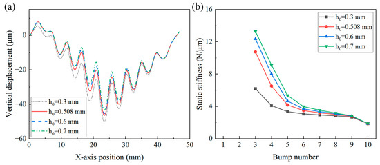
Figure 8.
Effect of bump height on (a) vertical displacement of top foil and (b) bump foil stiffness of the bump-type foil structure.
As shown in Figure 8, as the bump height increases, the vertical displacement of the top foil decreases, and the bump foil stiffness increases. That is, as the camber of the bump foil increases, the support provided by the bump foil to the top foil increases.
3.1.4. Effect of Friction Coefficient on Static Stiffness
In the contact model, there are two contact pairs for which the friction coefficient should be defined. For clarity, the friction coefficient for the pairing of the bump foil and top foil is defined as . Similarly, the friction coefficient for the pairing of the sleeve and bump foil is defined as . Figure 9 shows the vertical displacement distribution and stiffness curves of the bump-type foil structure with a constant and various . Three values of were considered, namely, 0.1, 0.2, and 0.3. Figure 10 shows the vertical displacement distribution and stiffness curves of the bump-type foil structure with a constant and various . Three values of were considered, namely, 0.1, 0.2, and 0.3.

Figure 9.
Effect of on (a) vertical displacement of top foil and (b) bump foil stiffness of the bump-type foil structure.
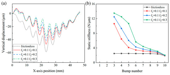
Figure 10.
Effect of on (a) vertical displacement of top foil and (b) bump foil stiffness of the bump-type foil structure.
As illustrated in Figure 9 and Figure 10, friction inhibited the vertical displacement of the top foil. As or increases, the inhibitory effect gradually increases. Furthermore, the effect was more evident in the middle position, where the applied load was higher. The presence of friction enhances the ability to hinder deformation, thereby improving the stiffness of the bump foil.
3.2. Static Performance Analysis under Various Eccentricities
In the following study, the mesh density in COMSOL is selected as Mesh 1, listed in Table 2, while the number of circumferential and axial mesh divisions in MATLAB is set to 150 and 10, respectively.
To validate the developed fully aeroelastic coupling model, the prediction data of our model, prediction data of the 2D top foil model [38], and experimental data [39] were compared. Figure 11 shows the relationship between (a) the minimum film thickness and (b) the journal attitude angle and load at 30 k rpm. The simulation results of our model showed good alignment with those in the literature, confirming the validity of our model. Moreover, compared with reference [38], the prediction of the attitude angle by our model aligns more closely with the experimental data [39].

Figure 11.
Relationship between (a) minimum film thickness, (b) journal attitude angle, and load [38,39].
In this section, four eccentricity values are considered: 0.1, 0.3, 0.5, and 0.7. The attitude angle was constant at 0°, and the rotational speed was constant at 30 k rpm. The static performance of the GFJBs with twenty-six bump foils was investigated.
3.2.1. Effect of Top Foil Thickness on Static Performance under Various Eccentricities
Figure 12 illustrates the effect of top foil thickness on load capacity and friction torque. The other foil parameters remained unchanged, and the top foil thicknesses were chosen as 0.05, 0.102, 0.15, and 0.3 mm. As shown in Figure 12(a1,b1), as the top foil thickness increased, the load capacity increased, and the friction torque changed very little. However, when the top foil is too thin, with a thickness of 0.05 mm, its deformation is very severe; consequently, the load capacity and friction torque decrease significantly. When journal eccentricity is 0.5, the load capacity and frictional torque of each bump foil are illustrated in Figure 12(a2,b2). As the thickness of the top foil increased, the load capacity and friction torque of each bump foil in the bearing zone increased. However, in the non-bearing zone, the influence was very limited.
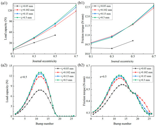
Figure 12.
Effect of top foil thickness on (a) load capacity and (b) friction torque of (1) the bearing and (2) each bump foil.
3.2.2. Effect of Bump Foil Thickness on Static Performance under Various Eccentricities
Figure 13 shows the effect of the bump foil thickness on the load capacity and friction torque. Other foil parameters remain unchanged, and the bump foil thicknesses are chosen as 0.102, 0.15, and 0.3 mm. As the bump foil thickness increased, the load capacity and friction torque increased. Furthermore, the effect was more evident at high eccentricities and concentrated in the main bearing zone.
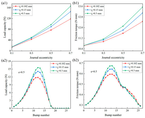
Figure 13.
Effect of bump foil thickness on (a) load capacity and (b) friction torque of (1) the bearing and (2) each bump foil.
3.2.3. Effect of Bump Height on Static Performance under Various Eccentricities
Figure 14 illustrates the effect of the bump height on the load capacity and friction torque. The other foil parameters remained unchanged, and the bump heights were chosen as 0.3, 0.508, 0.6, and 0.7 mm. With an increase in the bump height, the load capacity and friction torque increased, and the effect on each foil was concentrated in the main bearing zone.

Figure 14.
Effect of bump height on (a) load capacity and (b) friction torque of (1) the bearing and (2) each bump foil.
3.2.4. Effect of Radial Clearance on Static Performance under Various Eccentricities
Figure 15 shows the effect of the radial clearance on the load capacity and friction torque. The radial clearance is chosen as 15, 20, 30, and 40 µm. As shown in Figure 15, as the radial clearance increased, the load capacity and friction torque decreased. Moreover, as the radial clearance increased, the bearing zone shrank, and the friction torque in both the bearing and non-bearing zones decreased.

Figure 15.
Effect of radial clearance on (a) load capacity and (b) friction torque of (1) the bearing and (2) each bump foil.
3.3. Static Performance Analysis under Various Loads and Rotational Speeds
In studying the effect of load, seven different load values were considered: 5, 30, 50, 80, 100, 120, and 140 N, and the rotational speed was maintained at a constant value of 30 k rpm. To study the effect of rotational speed, seven different rotational speed values were considered: 10 k, 20 k, 30 k, 40 k, 50 k, 60 k, and 80 k rpm, with a constant load of 30 N.
3.3.1. Effect of Top Foil Thickness on Static Performance under Various Loads and Rotational Speeds
Figure 16 illustrates the effects of the load and rotational speed on the journal eccentricity for various top foil thicknesses. The other foil parameters remained unchanged, and the top foil thicknesses were chosen as 0.05, 0.102, 0.15, and 0.3 mm. When the load and rotational speed were varied, journal eccentricity decreased as the top foil thickness increased. This is because, given a constant eccentricity ratio, an increase in the top foil thickness leads to reduced deformability, which in turn enhances the load-bearing capacity of the bearing. With a constant top foil thickness, as the load increased or the rotational speed decreased, the journal eccentricity increased. As the load increases, the journal necessitates a greater eccentricity to generate a higher gas film load capacity, thereby counteracting the increased load. Conversely, when the rotational speed increases, more gas is entrained into the converging wedge, enhancing the hydrodynamic pressure effect and resulting in a larger gas film pressure. Consequently, the increase in rotational speed contributes to reducing the eccentricity of the journal.
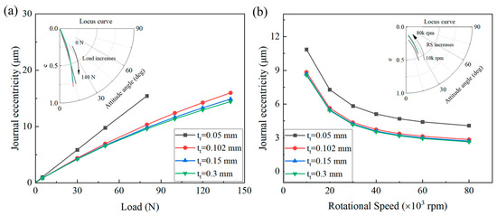
Figure 16.
Effects of (a) load and (b) rotational speed on journal eccentricity under various top foil thicknesses.
Figure 17a,b show the gas film thickness and gas film pressure with various top foil thicknesses under a load of 80 N and rotational speed of 30 k rpm, respectively. The values were averaged in the axial direction. As the thickness of the top foil decreased, its stiffness decreased, and its deformation increased; consequently, the fluctuation became more evident.
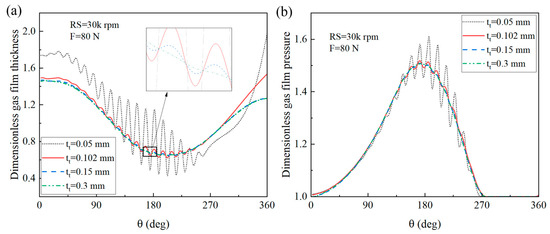
Figure 17.
(a) Gas film thickness and (b) gas film pressure under various top foil thicknesses.
Figure 18 illustrates the effects of the load and rotational speed on the minimum gas film thickness and maximum gas film pressure for various top foil thicknesses. As the rotational speed increased or load decreased, the minimum gas film thickness increased. For a specified load and rotational speed, as the top foil thickness increased, the minimum gas film increased.

Figure 18.
Effects of (a) load and (b) rotational speed on (1) minimum gas film thickness and (2) maximum gas film pressure under various top foil thicknesses.
As the thickness of the top foil increased, the maximum gas film pressure decreased. When the top foil thickness was maintained at a constant value, the maximum gas film pressure increased as the load increased or the rotational speed decreased. However, a local peak value of the gas pressure appeared when the top foil was too thin, with a thickness of 0.05 mm.
3.3.2. Effect of Bump Foil Thickness on Static Performance under Various Loads and Rotational Speeds
Figure 19 illustrates the effects of the load and rotational speed on the journal eccentricity for various top foil thicknesses. The other foil parameters remained unchanged, and the bump foil thicknesses were chosen as 0.05, 0.102, 0.15, and 0.3 mm. For a specified load and rotational speed, as the bump foil thickness increased, the journal eccentricity decreased. This is because, as the bump foil thickness increases, its stiffness is enhanced, leading to an elevation in the gas film load capacity. Consequently, the journal eccentricity required to generate sufficient gas film pressure to counterbalance the load demand decreases. With an increased load, the effect of the bump foil thickness on the journal eccentricity became more significant.
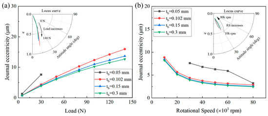
Figure 19.
Effects of (a) load and (b) rotational speed on journal eccentricity under various bump foil thicknesses.
Figure 20a,b show the gas film thickness and gas film pressure for various top foil thicknesses under a load of 30 N and a rotational speed of 30 k rpm, respectively. As the bump foil thickness increases, the main bearing zone gradually moves to the middle position. This is because as the bump foil thickness increases, its stiffness increases, and the load capacity increases accordingly.
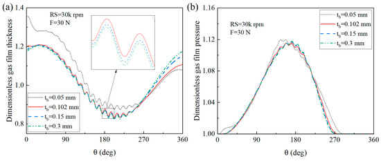
Figure 20.
(a) Gas film thickness and (b) gas film pressure under various bump foil thicknesses.
Figure 21 illustrates the effects of the load and rotational speed on the minimum gas film thickness and maximum gas film pressure for various bump foil thicknesses. As the bump foil thickness increased, the minimum gas film thickness decreased slightly, and the maximum gas film pressure increased slightly. With a low bump foil stiffness, the supporting effect was weak, the top foil deformation was severe, and the local peak value of the gas film pressure appeared.
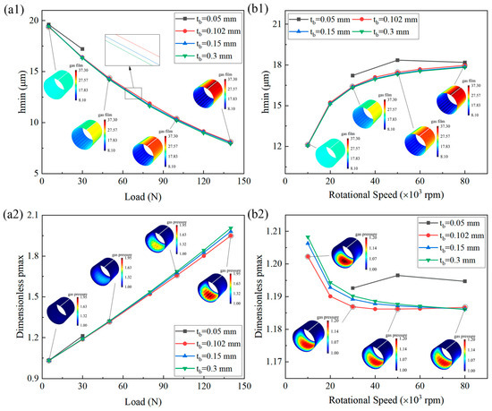
Figure 21.
Effects of (a) load and (b) rotational speed on (1) minimum gas film thickness and (2) maximum gas film pressure under various bump foil thicknesses.
3.3.3. Effect of Bump Height on Static Performance under Various Loads and Rotational Speeds
Figure 22 illustrates the effects of the load and rotational speed on the journal eccentricity under various bump heights. Other foil parameters remain unchanged; the bump height is chosen as 0.3, 0.508, 0.6, and 0.7 mm. For various loads, as the bump height increases, the journal eccentricity decreases. This is because as the bump height increases, its stiffness is enhanced. The larger the load, the more significant the effect. However, for various rotational speeds, the bump height had little effect on journal eccentricity.
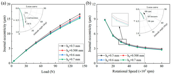
Figure 22.
Effects of (a) load and (b) rotational speed on journal eccentricity under various bump heights.
Figure 23a,b show the gas film thickness and pressure with various bump heights under a load of 80 N and a rotational speed of 30 k rpm, respectively. As the bump height increased, the fluctuation in the gas film pressure became obvious.

Figure 23.
(a) Gas film thickness and (b) gas film pressure under different bump heights.
Figure 24 illustrates the effects of the load and rotational speed on the minimum gas film thickness and maximum gas film pressure at various bump heights. As shown in Figure 24, at various loads or rotational speeds, the bump height has little effect on the minimum gas film thickness. The maximum gas film pressure was slightly affected by the bump height under various loads. However, at various rotational speeds, the maximum gas film pressure increased as the bump height increased.
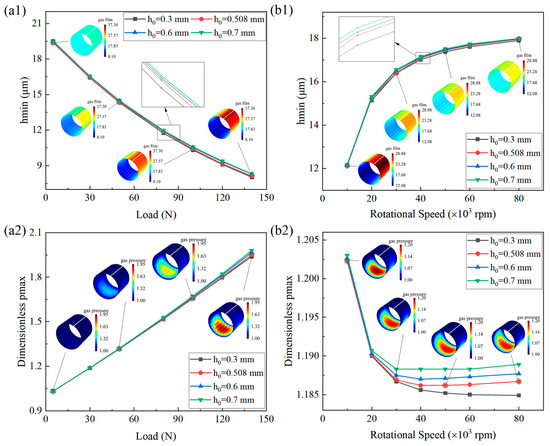
Figure 24.
Effects of (a) load and (b) rotational speed on (1) minimum gas film thickness and (2) maximum gas film pressure under various bump heights.
3.3.4. Effect of Radial Clearance on Static Performance under Various Loads and Rotational Speeds
Figure 25 illustrates the effects of the load and rotational speed on the journal eccentricity under various radial clearances. Other parameters remain unchanged; the radial clearance is chosen as 15, 20, 30, and 40 μm. As shown in Figure 25, for a specified load and rotational speed, the journal eccentricity decreased as the radial clearance increased. Furthermore, as the load increases and the rotational speed decreases, the effects become more significant. This is because when the radial clearance decreases, the flow velocity of the lubricant within the clearance increases relatively, thereby enhancing the hydrodynamic pressure effect, and as the eccentricity increases, this enhancing effect becomes more pronounced.
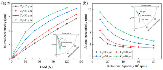
Figure 25.
Effects of (a) load and (b) rotational speed on journal eccentricity under various radial clearances.
Figure 26a,b show the gas film thickness and pressure with various radial clearances under a load of 50 N and a rotational speed of 30 k rpm, respectively. As shown in Figure 26, as the radial clearance increased, the peak value of the gas film pressure increased, the bearing zone shrank, and the fluctuation decreased.
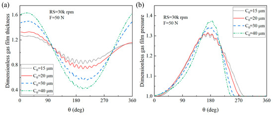
Figure 26.
(a) Gas film thickness and (b) gas film pressure under various radial clearances.
Figure 27 illustrates the effects of the load and rotational speed on the minimum gas film thickness and maximum gas film pressure under various radial clearances. For a specified load and rotational speed, as the radial clearance increased, the minimum gas film thickness decreased, and the maximum gas film pressure increased. Furthermore, the effects were more significant in the low-speed and heavy-load zones.
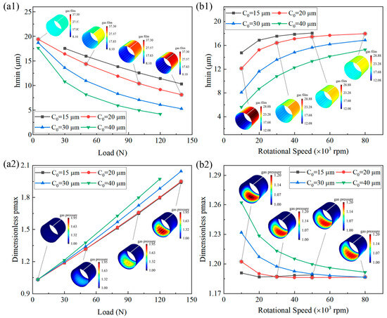
Figure 27.
Effects of (a) load and (b) rotational speed on (1) minimum gas film thickness and (2) maximum gas film pressure under various radial clearances.
4. Conclusions
In this study, the static stiffness and performance of the GFJBs were investigated. The elastic–aerodynamic coupling lubrication model was established using a co-simulation of MATLAB and COMSOL. Under given load and rotational speed conditions, the minimum gas film thickness and attitude angle were calculated, and the results were compared with those in the literature, showing a good agreement, which verified the accuracy of the model. Based on this, the effects of foil structural parameters under various operating conditions were explored. The following conclusions were drawn.
As the bump foil thickness, bump height, and friction coefficient increased, the bump foil stiffness also increased. The top foil thickness affected only the stiffness of the bump foil near the fixed end. Among these, the bump foil thickness had the most significant effect on the bump foil stiffness.
As the eccentricity increased, the load capacity and friction torque also increased. For a specified eccentricity, as the top foil thickness increased, the load capacity increased, whereas the friction torque changed very little. As the bump foil thickness and bump height increased, the load capacity and friction torque increased, and the effects were mainly concentrated in the main bearing zone. As the radial clearance increased, the load capacity and friction torque decreased, and the bearing zone shrunk. The bump foil thickness and radial clearance significantly affected the load capacity.
As the load increased or the rotational speed decreased, the journal eccentricity increased. For a specified load and rotational speed, the journal eccentricity decreased as the bump foil thickness, top foil thickness, and bump height increased; the journal eccentricity increased as the radial clearance increased.
The effects of various structural parameters and operating conditions should be considered when designing the GFJBs. The results offer theoretical support for the structural design of GFJBs with high reliability and long lifetimes. Because the dynamic performance of GFJBs is also important for design, further studies will focus on the effects of the foil structural parameters on the dynamic performance analysis of GFJBs after extending the developed model for dynamic simulation.
Author Contributions
Conceptualization, Y.H. and Y.M.; Methodology, Y.H.; Software, X.W.; Validation, P.D.; Formal analysis, X.W. and Y.M.; Investigation, P.D.; Writing—original draft, P.D. and Y.H.; Visualization, X.W.; Supervision, Y.H.; Project administration, Y.M.; Funding acquisition, Y.H. and X.W. All authors have read and agreed to the published version of the manuscript.
Funding
This work was supported by the National Natural Science Foundation of China (Nos. 52275204, 52075311, 51905298) and the Shanghai Key Laboratory of Intelligent Manufacturing and Robotics.
Data Availability Statement
Data are contained within the article.
Conflicts of Interest
The authors declare no conflict of interest.
Nomenclature
| gas film pressure, | Young’s modulus, | ||
| gas film thickness, | Poisson’s ratio | ||
| , | circumferential and axial positions, | air viscosity, | |
| ambient pressure, | radial component of load capacity, | ||
| radial clearance, | tangential component of load capacity, | ||
| dimensionless gas film pressure, | dimensionless radial component of load capacity, | ||
| dimensionless gas film thickness, | dimensionless tangential component of load capacity, | ||
| bearing radius, | load capacity, | ||
| bearing length, | friction torque, | ||
| top foil thickness, | dimensionless friction torque, | ||
| bump foil thickness, | axis of the coordinate | ||
| bump pitch, | eccentricity of the journal | ||
| half bump length, | rotational speed, | ||
| bump height, | external load, | ||
| attitude angle | top foil deformation | ||
| dimensionless circumferential and axial positions | original position of the material particle | ||
| new position of the material particle | deformation gradient of the material particle | ||
| pure rotation matrix | right extension tensor | ||
| elongation | three orthogonal directional components of | ||
| current length and original length of the material | Green–Lagrange strain tensor | ||
| matrices used in Equation (12) | relative velocity, | ||
| contact force, | friction coefficient | ||
| spring constant and its peak, | friction force, | ||
| flow rates per unit length in directions and | bearing number, | ||
| flow rates through the four faces of the control volume | coefficients used in Equation (18) | ||
| angular velocity of the journal, |
References
- Song, L.; Cheng, K.; Ding, H.; Chen, S. Analysis on discharge coefficients in FEM modeling of hybrid air journal bearings and experimental validation. Tribol. Int. 2018, 119, 549–558. [Google Scholar] [CrossRef]
- Lehn, A.; Mahner, M.; Schweizer, B. Elasto-gasdynamic modeling of air foil thrust bearings with a two-dimensional shell model for top and bump foil. Tribol. Int. 2016, 100, 48–59. [Google Scholar] [CrossRef]
- Pattnayak, M.; Ganai, P.; Pandey, R.; Dutt, J.; Fillon, M. An overview and assessment on aerodynamic journal bearings with important findings and scope for explorations. Tribol. Int. 2022, 174, 107778. [Google Scholar] [CrossRef]
- Samanta, P.; Murmu, N.; Khonsari, M. The evolution of foil bearing technology. Tribol. Int. 2019, 135, 305–323. [Google Scholar] [CrossRef]
- Walowit, J.A.; Anno, J.N.; Hamrock, B.J. Modern developments in lubrication mechanics. J. Lubr. Technol. 1977, 99, 304–305. [Google Scholar] [CrossRef]
- Heshmat, H.; Walowit, J.A.; Pinkus, O. Analysis of gas-lubricated foil journal bearings. J. Lubr. Technol. 1983, 105, 647–655. [Google Scholar] [CrossRef]
- Iordanoff, I. Analysis of an aerodynamic compliant foil thrust bearing: Method for a rapid design. J. Tribol. 1999, 121, 816–822. [Google Scholar] [CrossRef]
- Swanson, E.E. Bump foil damping using a simplified model. J. Tribol. 2006, 128, 542–550. [Google Scholar] [CrossRef][Green Version]
- Le Lez, S.; Arghir, M.; Frene, J. A new bump-type foil bearing structure analytical model. J. Eng. Gas Turbines Power 2007, 129, 1047–1057. [Google Scholar] [CrossRef]
- Gu, Y.; Ren, G.; Zhou, M. A fully coupled elastohydrodynamic model for static performance analysis of gas foil bearings. Tribol. Int. 2020, 147, 106297. [Google Scholar] [CrossRef]
- Gu, Y.; Lan, X.; Ren, G.; Zhou, M. An efficient three-dimensional foil structure model for bump-type gas foil bearings considering friction. Friction 2021, 9, 1450–1463. [Google Scholar] [CrossRef]
- Arghir, M.; Benchekroun, O. A simplified structural model of bump-type foil bearings based on contact mechanics including gaps and friction. Tribol. Int. 2019, 134, 129–144. [Google Scholar] [CrossRef]
- Nielsen, B.B.; Santos, I.F. Transient and steady state behaviour of elasto-aerodynamic air foil bearings, considering bump foil compliance and top foil inertia and flexibility: A numerical investigation. Proc. Inst. Mech. Eng. Part J J. Eng. Tribol. 2017, 231, 1235–1253. [Google Scholar] [CrossRef]
- Gad, A.M.; Kaneko, S. A New Structural Stiffness Model for Bump-Type Foil Bearings: Application to Generation II Gas Lubricated Foil Thrust Bearing. J. Tribol. 2014, 136, 041701. [Google Scholar] [CrossRef]
- Andre´s, L.S.; Kim, T.H. Improvements to the analysis of gas foil bearings: Integration of top foil 1D and 2D structural models. In Proceedings of the Turbo Expo 2007: Power for Land, Sea, and Air, Montreal, QC, Canada, 14–17 May 2007; pp. 779–789. [Google Scholar]
- Lee, Y.-B.; Park, D.-J.; Kim, C.-H.; Kim, S.-J. Operating characteristics of the bump foil journal bearings with top foil bending phenomenon and correlation among bump foils. Tribol. Int. 2008, 41, 221–233. [Google Scholar] [CrossRef]
- Feng, K.; Kaneko, S. Analytical model of bump-type foil bearings using a link-spring structure and a finite-element shell model. J. Tribol. 2010, 132, 021706. [Google Scholar] [CrossRef]
- Carpino, M.; Talmage, G. A fully coupled finite element formulation for elastically supported foil journal bearings. Tribol. Trans. 2003, 46, 560–565. [Google Scholar] [CrossRef]
- Sim, K.; Kim, T.H. Thermohydrodynamic analysis of bump-type gas foil bearings using bump thermal contact and inlet flow mixing models. Tribol. Int. 2012, 48, 137–148. [Google Scholar] [CrossRef]
- Feng, K.; Kaneko, S. A Thermohydrodynamic Sparse Mesh Model of Bump-Type Foil Bearings. J. Eng. Gas Turbines Power 2013, 135, 022501. [Google Scholar] [CrossRef]
- Lee, D.; Kim, D. Thermohydrodynamic Analyses of Bump Air Foil Bearings with Detailed Thermal Model of Foil Structures and Rotor. J. Tribol. 2010, 132, 021704. [Google Scholar] [CrossRef]
- Lehn, A.; Mahner, M.; Schweizer, B. A thermo-elasto-hydrodynamic model for air foil thrust bearings including self-induced convective cooling of the rotor disk and thermal runaway. Tribol. Int. 2018, 119, 281–298. [Google Scholar] [CrossRef]
- Qin, K.; Jacobs, P.A.; Keep, J.A.; Li, D.; Jahn, I.H. A fluid-structure-thermal model for bump-type foil thrust bearings. Tribol. Int. 2018, 121, 481–491. [Google Scholar] [CrossRef]
- Bin Hassan, M.; Bonello, P. A new modal-based approach for modelling the bump foil structure in the simultaneous solution of foil-air bearing rotor dynamic problems. J. Sound Vib. 2017, 396, 255–273. [Google Scholar] [CrossRef]
- Chakraborty, B.; Biswas, N.; Chakraborti, P. An Investigation to Find the Effects on Air Foil Bearing by the Variation of Foil’s Structural Parameters. J. Sci. Ind. Res. 2023, 82, 603–608. [Google Scholar] [CrossRef]
- Zywica, G.; Baginski, P.; Bogulicz, M.; Martowicz, A.; Roemer, J.; Kantor, S. Numerical identification of the dynamic characteristics of a nonlinear foil bearing structure: Effect of the excitation force amplitude and the assembly preload. J. Sound Vib. 2022, 520, 116663. [Google Scholar] [CrossRef]
- Fatu, A.; Arghir, M. Numerical Analysis of the Impact of Manufacturing Errors on the Structural Stiffness of Foil Bearings. J. Eng. Gas Turbines Power 2018, 140, 041506. [Google Scholar] [CrossRef]
- Liu, Z.-S.; Zhang, G.-H.; Xu, H.-J. Performance analysis of rotating externally pressurized air bearings. Proc. Inst. Mech. Eng. Part J J. Eng. Tribol. 2009, 223, 653–663. [Google Scholar] [CrossRef]
- Wang, X.; Xu, Q.; Wang, B.; Zhang, L.; Yang, H.; Peng, Z. Numerical calculation of rotation effects on hybrid air journal bearings. Tribol. Trans. 2017, 60, 195–207. [Google Scholar] [CrossRef]
- Howard, S.A. Preliminary development of characterization methods for compliant air bearings. Tribol. Trans. 1999, 42, 789–794. [Google Scholar] [CrossRef]
- Chiu, C.; Cheng, Y. Influences of operational conditions and geometric parameters on the stiffness of aerostatic journal bearings. Precis. Eng. 2010, 34, 722–734. [Google Scholar] [CrossRef]
- Lee, D.-H.; Kim, Y.-C.; Kim, K.-W. The static performance analysis of foil journal bearings considering three-dimensional shape of the foil structure. J. Tribol. 2008, 130, 031102. [Google Scholar] [CrossRef]
- Kim, D. Parametric studies on static and dynamic performance of air foil bearings with different top foil geometries and bump stiffness distributions. J. Tribol. 2007, 129, 354–364. [Google Scholar] [CrossRef]
- Larsen, J.S.; Hansen, A.J.T.; Santos, I.F. Experimental and theoretical analysis of a rigid rotor supported by air foil bearings. Mech. Ind. 2015, 16, 106. [Google Scholar] [CrossRef]
- Wang, X.; Xu, Q.; Wang, B.; Zhang, L.; Yang, H.; Peng, Z. Effect of surface waviness on the static performance of aerostatic journal bearings. Tribol. Int. 2016, 103, 394–405. [Google Scholar] [CrossRef]
- Dal, A.; Karaçay, T. Effects of angular misalignment on the performance of rotor-bearing systems supported by externally pressurized air bearing. Tribol. Int. 2017, 111, 276–288. [Google Scholar] [CrossRef]
- COMSOL. LiveLink™ for MATLAB® User’s Guide, Part Number: CM020008. Available online: https://doc.comsol.com/5.4/doc/com.comsol.help.llmatlab/LiveLinkForMATLABUsersGuide.pdf (accessed on 30 November 2022).
- Andrés, L.S.; Kim, T.H. Analysis of gas foil bearings integrating FE top foil models. Tribol. Int. 2009, 42, 111–120. [Google Scholar] [CrossRef]
- Ruscitto, D.; McCormick, J.; Gray, S. Hydrodynamic Air Lubricated Compliant Surface Bearing for an Automotive Gas Turbine Engine. 1: Journal Bearing Performance; CONS-9427-1; NASA-CR-135368; Mechanical Technology, Inc.: Latham, NY, USA, 1978. [Google Scholar] [CrossRef]
Disclaimer/Publisher’s Note: The statements, opinions and data contained in all publications are solely those of the individual author(s) and contributor(s) and not of MDPI and/or the editor(s). MDPI and/or the editor(s) disclaim responsibility for any injury to people or property resulting from any ideas, methods, instructions or products referred to in the content. |
© 2024 by the authors. Licensee MDPI, Basel, Switzerland. This article is an open access article distributed under the terms and conditions of the Creative Commons Attribution (CC BY) license (https://creativecommons.org/licenses/by/4.0/).