Abstract
During operation, angular contact ball bearings exhibit slipping behavior, which accelerates bearing wear and reduces the bearing’s overall service life. This paper focuses on studying the degree of slippage and the variation in slippage rate in the H7006C angular contact ball bearing under constant inner ring speed and angular acceleration conditions. To achieve this objective, the study defines the contact between rolling elements, inner and outer rings, and the cage as flexible. A rigid–flexible coupling slippage dynamic simulation model is then developed, which utilizes cage slippage rate as the evaluation index. The analysis method of cage slippage rate change is established through the Gaussian function fitting method. By comparing simulation and testing results, the effectiveness of the analysis method of angular contact ball bearing slip behavior is validated. On this basis, the influence law of bearing speed and acceleration conditions on the slipping behavior of angular contact ball bearings is further studied. The results of the study show that as the axial load increases at different inner ring speeds, the cage speed increases until it reaches a stable state, while the cage slip rate continuously decreases until reaching a stable state. The higher the inner ring speed, the greater the axial load required for the bearing to enter the steady state. Under different angular accelerations, the cage speed increases with time; when the cage speed increases to stable and constant, the cage slip rate decreases to a stable state, and the higher the angular acceleration, the longer it takes for the bearing to enter the stable state.
1. Introduction
Under ideal conditions, the rolling elements of bearings experience pure rolling motion between the raceways. However, in actual working conditions, relative sliding (cage slippage) occurs between the rolling body and raceway, leading to frictional wear on the contact surface of the raceway and rolling body. This slippage also generates spindle vibration that can cause burns and, in severe cases, reduces the bearing’s service life and reliability. Therefore, it is highly important from an engineering perspective to study the slip characteristics of rolling bearings under operating conditions.
Scholars have conducted an analysis of the primary causes of slippage in rolling bearings for various application scenarios and have subsequently proposed a diverse range of analytical and experimental methods for researching the slippage characteristics of such bearings. Han, Q.K. [1] studied the effects of increasing radial load, moment, and time-varying load on the roller slip of cylindrical roller bearings by establishing a nonlinear dynamic model. Fang Bin et al. [2] proposed a comprehensive mathematical model to predict the sliding behavior of angular contact ball bearings and, based on the model, analyzed the effect of skidding on bearing heating and temperature rise. Pederson et al. [3] proposed a dynamic flexible cage model under the assumption that cage flexibility is represented by the lumped mass method. The results show that the circumferential stiffness of the cage has a great influence on the contact force of the rolling body and the dynamic performance of the cage. Weinzapfel et al. [4] established a discrete element model representing the flexible cage and analyzed the interaction between the roller and the cage. By comparing the calculation results of rigid and flexible cage models, it is found that cage flexibility can significantly reduce the collision force between the rolling body and cage. Sier D [5] established the nonlinear dynamic differential equations of sliding behavior of three-raceway cylindrical roller bearings. The effects of bearing working conditions and different load conditions on bearing skid characteristics were studied. Cui, Y.C. et al. [6] established a dynamic analysis model of cage dynamic imbalance to analyze the influence of dynamic imbalance on the cage slip characteristics of the cylindrical roller bearing cage. Kang [7] used a six-degree-of-freedom dynamic bearing model to analyze the slip characteristics of the bearing under low load, transient acceleration, and deceleration conditions. Laniado [8] employed a finite element simulation analysis to investigate the sliding occurring between the rolling elements and raceways of cylindrical roller bearings. Shao et al. [9] investigated the action force and centrifugal force between the rolling body and the cage. They established a dynamic model for the slipping of the rolling body in the load-bearing area and examined the mechanism and characteristics of this slipping phenomenon. Wang [10] investigated the relationship between the operating conditions and the degree of sliding in angular contact ball bearings under different axial load conditions by establishing a dynamic model for the sliding phenomenon. Takabi [11] used a tribological model of the local friction coefficient to simulate the rolling contact of bearings under alternating loads based on dynamic simulations. Niu et al. [12] conducted a study utilizing dynamic simulations to investigate the phenomenon of stable cage whirl guided by the outer ring in a ball bearing operating under solid lubrication conditions. YuQing Liu et al. [13] investigated the impact of cage radial load, inner ring acceleration, and connection stiffness between mass blocks on bearing sliding by utilizing a dynamic model. Laily Oktaviana et al. [14] used the five-degree-of-freedom quasi-static model to analyze the sliding characteristics of angular contact ball bearings under different boundary conditions. Jain et al. [15] developed a dynamic model that considers centrifugal effects to investigate the slippage characteristics of angular contact ball bearings. The model utilizes elastohydrodynamic (EHD) lubrication theory to analyze the basic slippage mechanisms under pure axial loads and combined radial and axial loads. Wenbing Tu et al. [16] established an analytical model of rolling bearings to study the slippage phenomenon and the transient motion behavior of rolling bearings during acceleration. Shuaijun Ma [17] studied the peak impact forces of rotational speed, radial load, acceleration and deceleration, and material on two adjacent rolling bodies and cages from the perspective of the relative sliding velocity between the rolling body and raceway, based on the bearing dynamic model. Gao [18] proposed an integrated model, known as the kinematic-hertzian-thermodynamic-hydrodynamic model, to investigate and forecast the occurrence of overslip and slip mechanisms.
In terms of experimental research, Cocks et al. [19] utilized a double-ball sliding testing machine to investigate how different factors, including rolling speed, sliding speed, lubricating oil flow, ambient temperature, load increase rate, ball surface roughness, and others, impact skid damage in ball bearings. Selvaraj, A. et al. [20] used a cylindrical roller bearing test bed to study the influence of running parameters such as bearing speed, radial load, lubricating oil viscosity, number of rollers, and bearing temperature on cage sliding. Both Li, J.N. and Li, Q. [21,22] used sliding testing machines to study the formation mechanism of sliding damage of rolling bearings caused by different slip combinations and the dynamic characteristics of bearing cage under different loads and speeds under two conditions: inner ring fixed, outer ring rotating, and opposite rotation directions of inner and outer rings. Mark [23] studied the changes in mechanical properties, friction coefficient, friction power intensity, elastohydrodynamic lubricating oil film thickness, and temperature between roller and raceway after skidding damage of cylindrical roller bearings based on a two-roll testing machine. Xu Chan [24] conducted experimental and numerical studies to investigate the interaction mechanism between skidding, surface wear, and uneven vibration. Cui, L. [25] conducted research on the minimum load required to prevent slippage in rolling bearings and the maximum critical load to prevent overheating using a high-speed rolling bearing test machine. Gao [26] performed an overslip test on angular contact ball bearings using an industrial-scale test rig to examine the impact of axial load, rotational speed, and lubrication on overslip behavior.
In the above studies, scholars have analyzed the factors and parameters that lead to bearing slippage behavior from both theoretical analysis and experimental research. In response to the slippage problem of angular contact ball bearings in machine tool spindles, this paper selects the H7006C angular contact ball bearing as the research object and utilizes the cage slippage rate as the evaluation index. The aim of this study is to investigate the degree of bearing slippage and the variation of slippage rate under constant speed and angular acceleration working conditions. To address this research, a rigid–flexible coupling dynamic simulation model is implemented by integrating the finite element and multi-body dynamic methods. This model considers the flexible contact between the rolling elements, inner and outer rings, and the cage. Using the developed bearing slippage motion simulation test device, the simulation and test results are compared to validate the effectiveness of the rigid–flexible coupling model. Based on this model, the Gaussian function fitting method is employed to develop a basis for assessing the degree of cage slippage and further explore the impact of bearing speed and acceleration conditions on the slippage behavior of angular contact ball bearings.
2. Angular Contact Ball Bearing Rigid–Flexible Coupling Motion Analysis
2.1. Angular Contact Ball Bearing Rigid–Flexible Coupling Motion Simulation Model
The relative motion between bearing components is mainly transmitted through contact forces, and the rigid body model [4] ignores the influence of flexible body deformation on the dynamic response of the bearing and cannot accurately simulate the motion of the rolling body. The schematic diagram of the rigid body model of the angular contact ball bearing is shown in Figure 1. In the OXY coordinate system, the inner ring rotates with the angular velocity of , and the angular velocity of the rolling body and cage are , . The jth rolling body has contact forces , , , and and friction forces , , , and with the inner and outer ring at the angular position .
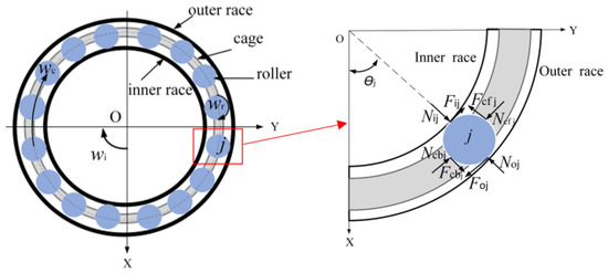
Figure 1.
Schematic diagram of rigid connection model of angular contact ball bearing.
In order to accurately simulate the motion of the rolling element and cage of the bearing, a rigid–flexible coupling dynamic model of the angular contact ball bearing is established, as shown in Figure 2; material characteristics of angular contact ball bearing are shown in Table 1. The cage is divided discretely into several segments with the same number of rolling units. In the O’X’Y’ coordinate system, the relationship between forces and contacts during component collisions is determined by elastic forces and damping forces. Specifically, the contact stiffness between the rolling body and the inner ring is denoted as , with damping denoted as . The contact stiffness between the rolling body and the outer ring is denoted as , with damping denoted as . The contact stiffness between the rolling body and the cage is denoted as , with damping denoted as .
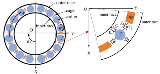
Figure 2.
Schematic diagram of rigid–flexible coupling model of angular contact ball bearing.

Table 1.
Material characteristics of H7006C angular contact ball bearing.
In bearing motion, the internal force is mainly composed of the contact force and friction force generated by contact deformation between the rolling body and the inner and outer ring and cage.
In the rigid–flexible model, the contact relationship between the j′th rolling body and the inner and outer ring and cage can be defined by the following impact contact force function:
where is the contact force at collision, is the actual distance between two contacts after collision, is the initial distance between two contacts, is the contact stiffness, and is the normal contact pressure index; for point contact, is 1.5. is the damping coefficient damping factor, is the relative velocity between the two contacts, is the normal penetration depth, and step is the step function.
The contact between the bearing components is usually point or line contact, so the stiffness value can be calculated according to the Hertzian contact theory [27]. The contact stiffness is calculated as shown in the following equation:
where is the equivalent elastic modulus; is the equivalent contact radius; and are the elastic moduli of the two colliding bodies; and are the two collision bodies of Poisson’s ratio; and and are the two collision bodies of the radius, respectively.
In Equation (1), the contact damping is determined using the method proposed by Hunt, as follows [28]:
where is the contact recovery coefficient; is the deformation index, and for a Hertzian linear contact problem, = 10/9; is the contact deformation of the two components for the Palmgren linear contact convergence [29], and is the component contact load.
The frictional forces between the rolling elements and the cage, as well as between the inner and outer rings, are calculated using the Coulomb model, considering the friction coefficient between the contacting surfaces.
where is the sign function, affecting the positive and negative values of the dynamic friction factor; is the relative slip velocity between the two contacting bodies; is the dynamic friction factor of the two contacting bodies; is the dynamic slip velocity; is the static friction factor of the two contacting bodies; and is the static slip velocity.
On the basis of the determination of contact force and friction factor, the friction force between the j′th rolling body and the inner and outer rings and cage is expressed as
where is the friction factor determined by Equation (7), and the contact force with is determined by Equation (1).
During the simulation, the variation in the inner ring speed of the bearing can be achieved using the step function. This function provides power for the rotation of the bearing and serves the purpose of simulating bearing slippage. The bearing speed variation function, , is calculated as provided below:
Let , , and then
where is simulation time, is the initial value of the time variable, is the end value of the time variable, is the initial value of the external excitation, and is the final value of the external excitation.
2.2. Angular Contact Ball Bearing Slippage Analysis Method
Calculating the cage slip rate determines the angular contact ball bearing slippage state [30]. The bearing slip state is analyzed by calculating and analyzing the bearing simulation speed data set, linear fitting of discrete points of the slip rate, and the determination of the critical point of the slip state. The specific method is shown in Figure 3.
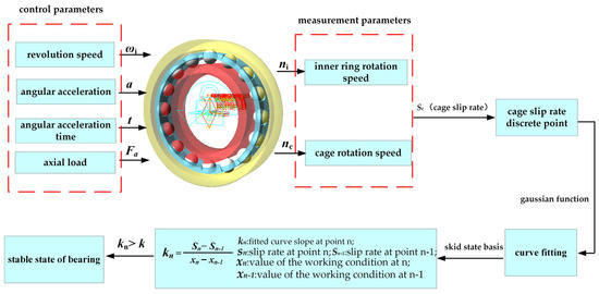
Figure 3.
Flowchart of the slip state analysis method.
- (1)
- Simulation of rigid–flexible coupled angular contact ball bearing slippage in multi-body dynamic simulation software was carried out to obtain cage speed and inner ring speed data sets under different operating conditions.
- (2)
- The cage slip rate empirical formula is employed to calculate the slip rate of the cage under various working conditions and analyze the trend of discrete points within the data set of cage slip rates. The empirical equation for the cage slip rate is denoted as follows [30]:where is the cage slip rate; is the actual speed of the bearing cage; is the theoretical speed of the cage; is the speed of the inner ring; is the diameter of the rolling body of the bearing, is the diameter of the knuckle circle of the bearing, is the contact angle.
- (3)
- To ensure high accuracy in the fitting function, a Gaussian function is chosen for the linear fitting of the discrete points of the cage slip rate, expressed as follows:
- (4)
- By analyzing the trend of the fitted curve for the slippage rate, the slope of the curve is calculated and utilized as a basis for evaluating the bearing slippage condition. The formula for calculating the slope of the curve is as follows:
- (5)
- In the slip data set, the critical value points for the slip state of the cage are marked for different fitted curve functions. When the slope of the fitted curve is greater than , it is considered to be in a stable state; when the slope of the fitted curve is less than , it is considered to be in a slip state.
3. Angular Contact Ball Bearing Simulation Model Verification
Taking the example of a precision angular contact ball bearing H7006C used in machine tool spindles, the main parameters of the bearing are shown in Table 2.
Table 2.
Basic structural parameters of angular contact ball bearing H7006C.
Using the angular contact ball bearing rolling slip test system (as shown in Figure 4), the angular contact ball bearing slippage test is carried out to verify the validity of the rigid–flexible coupling simulation model. In the bearing roll–slip test platform, the inner ring of the bearing is solidly connected to the spindle motor, and the measured spindle speed is regarded as the inner ring speed of the bearing. The axial loading is achieved by a linear brake that drives a wire rope, which in turn moves the lever downwards. The clutch connected to the lever is actuated by the magnetic force of a permanent magnet, causing the bearing housing to move downward, thereby applying axial force to the test bearing. The principle of light reflection reception in optical fiber sensors is applied by affixing reflective strips to the motor spindle and cage, which enables the independent measurement of the cage speed and the inner ring speed . The cage slip rate Sc is calculated using Equations (11) and (12).
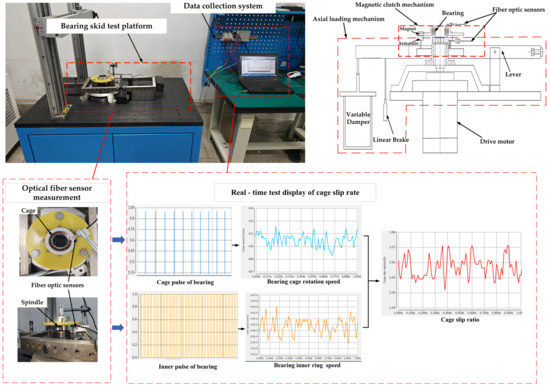
Figure 4.
Schematic diagram of experimental platform.
The contact stiffness between the rolling body, inner and outer ring, and cage in the simulation model is defined as = 1.866 , = 1.467 , and = 0.879. The Dynamic slip speed = 100 mm/s, the static slip speed = 1000 mm/s, the dynamic friction factor = 0.1, the static friction factor = 0.02, and the rated dynamic load of the bearing C = 200 N. According to ISO 281 standard (C/P), the simulation and test use the axial load P = 100 N, that is, the load factor C/P = 2 and the inner ring speed of 900~2700 rpm under the working conditions of the cage speed change with the time curve shown in Figure 5. Based on the average cage speed, the average cage slip rate of the test and simulation is shown in Figure 6.
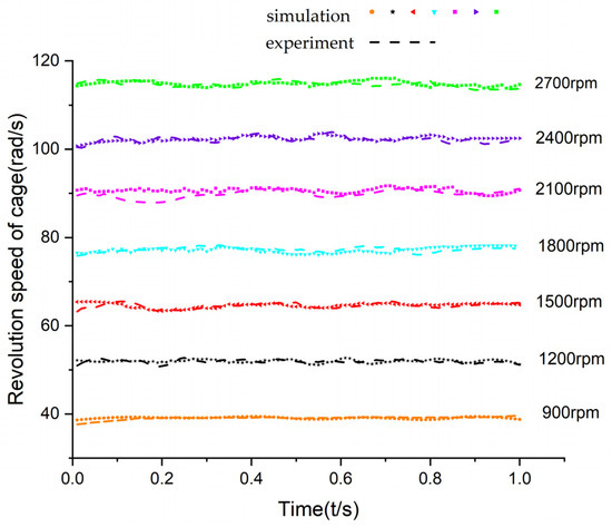
Figure 5.
Cage revolution speed under different inner rotational speeds.
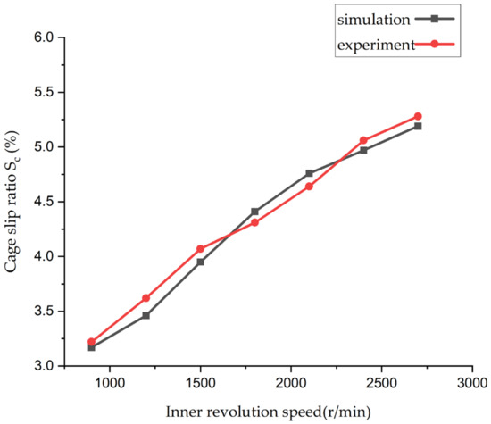
Figure 6.
Skid rates of cage under inner rotational speeds.
As shown in Table 3, the cage slip rate increases with the bearing speed, and the root mean square difference between the test and simulation is 0.11%, which verifies the validity of the simulation model.
Table 3.
Comparison of tested and simulated slip rates at different speeds.
4. Angular Contact Ball Bearing Slippage Rate Characteristic Law Analysis
In order to investigate the law of bearing slip characteristics, on the basis of verifying the validity of the simulation model, this section further investigates the simulation of the bearing under different speed and angular acceleration conditions. By calculating the center of mass speed of the cage in the simulation process, the law of change in the slip rate of the cage under different working conditions is analyzed.
4.1. Effect of Axial Load on Bearing Cage Slipping Characteristics
Simulations were carried out for bearing speeds of 1000~9000 rpm and axial loads of 50~700 N, that is, load factors C/P of 0.29~4, to analyze the effect of axial load changes on the average slip rate of the cage at different inner ring speeds. The angular speed of the cage is shown in Figure 7. The cage slip rate is calculated according to Equation (11) with the axial load variation law at different inner ring speeds, and the discrete points of the slip rate are fitted linearly with the axial load (x-axis) as the independent variable and the cage slip rate (y-axis) as the dependent variable, as shown in Figure 8.
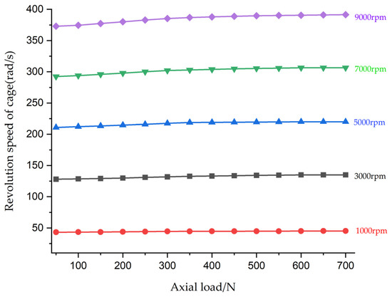
Figure 7.
Cage revolution curve under different axial loads.
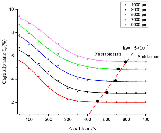
Figure 8.
Cage skidding rate under different axial loads.
The Gaussian function is used to linearly fit the slip rate dispersion points; Table 3 shows the comparison results of different sub-term functions for the cage slip rate dispersion points under axial load. SSE and RMSE converge more closely to 0, and the more R-square converges to 1, the better the curve is fitted.
From Table 4, the method of fitting using the Gaussian binomial function is more precise; that is, for the functional model of the change in bearing cage slip rate with axial load variation under constant inner ring rotation speed.
where is the cage slip rate; is the axial load; and , , , , , and are the function model parameters.
Table 4.
Axial Gaussian polynomial result.
The values of the model parameters for the variation of the slip rate of the cage with axial load under different speeds are shown in Table 5.
Table 5.
Axial load model parameters.
Based on the simulation model, Figure 7 illustrates the relationship between cage speed and axial load. When the axial load remains constant, the cage speed increases with the bearing speed. When the bearing speed is kept constant, the cage speed increases with the axial load until reaching a stable state. Figure 8 displays the fitting curve depicting the variation of cage slip rate with axial load for different inner ring speeds. The slip rate of the cage decreases gradually with the increase of axial load until it reaches a stable state. The critical value for the slope of the curve fitting change is = −5 × 10⁻⁶. When the slope of the curve exceeds , the bearing is considered to be in a stable state. When the bearing speed is higher, the slope of the fitted curve is greater than (into the stable state), and the greater the axial load required.
4.2. Influence of Acceleration Conditions on Bearing Cage Slippage Characteristics
The simulation was conducted using a step function with angular accelerations of 20 rad/s2, 40 rad/s2, 60 rad/s2, and 80 rad/s2, along with an axial load of 200 N, that is, load factors C/P = 1, to analyze the impact of different angular accelerations on the cage slip rate. The cage slip rates under different inner ring angular accelerations were calculated using Equation (11). The acceleration time was taken as the independent variable (x-axis), and the cage slip rate as the dependent variable (y-axis). The discrete points of the slip rate were subjected to linear fitting. Table 6 presents a comparison of different fitting functions for the discrete points of the cage slip rate under angular acceleration.
Table 6.
Acceleration Gaussian polynomial result.
From the above table, the method of fitting using the Gaussian univariate polynomial is more precise. That is, the functional model of the bearing cage slip rate’s change over time under angular acceleration is as follows:
where is the slip ratio of the cage under angular acceleration; , , and are the model parameters; and is the time of angular acceleration.
The values of the model parameters for the cage slip rate as a function of time for different angular acceleration speeds are shown in Table 7.
Table 7.
Acceleration model parameters.
The variation curve of the cage speed with time under accelerating conditions is depicted in Figure 9. At a certain time, with an increasing angular acceleration of the bearing, the cage speed increases while the slip rate decreases. The fitted curve representing the change in cage slip rate with time under different angular accelerations is shown in Figure 10. The critical value for the slope of the fitted curve is set at = −3 × 10⁻². When the slope of the curve exceeds , it indicates that the bearing has reached a stable state. As the angular acceleration conditions increase, it takes a longer time for the slope of the fitted curve to exceed and enter the stable state.
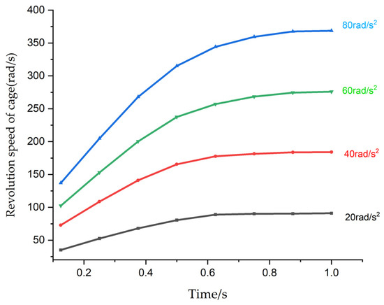
Figure 9.
Cage revolution speed under different angular accelerations.
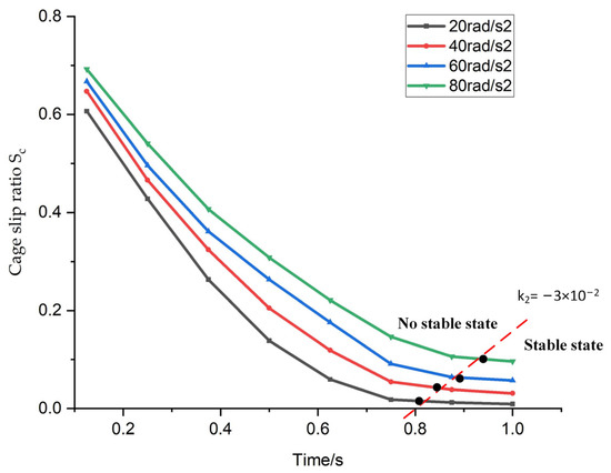
Figure 10.
Cage slip rate under different angular accelerations.
5. Conclusions
This paper is based on a rigid–flexible coupling dynamic simulation model of angular contact ball bearings and verifies the validity of the model by comparing the simulation and test cage slip rates. Based on this model, further dynamic simulation analysis is conducted on the slip characteristics of the bearing under different inner ring speeds, axial loads, and angular accelerations. The variation law of the angular contact ball bearing slip ratio is obtained, and the results are as follows:
- (1)
- Under different inner ring speeds, as the axial load increases, the speed of the cage increases, but the rate of speed increase gradually decreases until it reaches zero, and the cage speed remains constant. Simultaneously, the slip rate of the cage gradually decreases as the axial load increases until it reaches a constant value, indicating the onset of stable slipping. Higher inner ring speeds require larger axial loads for the cage to enter the stable slipping state;
- (2)
- Under different inner ring angular accelerations, when the axial load is constant, the lower the inner ring angular acceleration, the lower the slip rate of the cage, and the shorter the time required to reach the stable slipping stage. Therefore, when performing speed transitions, operating under conditions of low acceleration can reduce bearing wear and premature failures caused by slipping.
Author Contributions
Conceptualization, M.S.; methodology, M.S. and N.G.; software, M.S.; validation, F.Y. and M.S.; investigation, X.M.; resources, X.M.; data curation, N.G.; writing—original draft preparation, M.S.; writing—review and editing, M.S.; supervision, Y.X.; project administration, F.Y.; funding acquisition, F.Y. All authors have read and agreed to the published version of the manuscript.
Funding
This research was funded by Major Science and Technology Project of Henan Province (221100220100) and Frontier exploration Projects of Longmen Laboratory (NO. LMQYTSKT037).
Institutional Review Board Statement
Not applicable.
Informed Consent Statement
Not applicable.
Data Availability Statement
Data are contained within the article.
Conflicts of Interest
The authors declare no conflict of interest.
References
- Han, Q.; Li, X.; Chu, F. Skidding behavior of cylindrical roller bearings under time-variable load conditions. Int. J. Mech. Sci. 2018, 135, 203–214. [Google Scholar] [CrossRef]
- Fang, B.; Zhang, J.; Wan, S.; Hong, J. Determination of Optimum Preload Considering the Skidding and Thermal Characteristic of High-Speed Angular Contact Ball Bearing. J. Mech. Des. 2018, 140, 301–310. [Google Scholar] [CrossRef]
- Ghaisas, N.; Wassgren, C.R.; Sadeghi, F. Cage instabilities in cylindrical roller bearings. J. Tribol. 2004, 126, 681–689. [Google Scholar] [CrossRef]
- Weinzapfel, N.; Sadeghi, F. A discrete element approach for modeling cage flexibility in ball bearing dynamics simulations. J. Tribol. 2009, 131, 021102. [Google Scholar] [CrossRef]
- Deng, S.; Lu, Y.; Zhang, W.; Sun, X.; Lu, Z. Cage slip characteristics of a cylindrical roller bearing with a trilobe-raceway. Chin. J. Aeronaut. 2018, 31, 351–362. [Google Scholar] [CrossRef]
- Cui, Y.; Deng, S.; Yang, H.; Zhang, W.; Niu, R. Effect of cage dynamic unbalance on the cage’s dynamic characteristics in high-speed cylindrical roller bearings. Ind. Lubr. Tribol. 2019, 71, 1125–1135. [Google Scholar] [CrossRef]
- Kang, Y.S.; Evans, R.D.; Doll, G.L. Roller-Raceway Slip simulations of Wind Turbine Gearbox Bearings Using Dynamic Bearing Model. In Proceedings of the International Joint Tribology Conference, San Francisco, CA, USA, 17–20 October 2010; pp. 407–409. [Google Scholar]
- Laniado, J.E.; Meneses, A.J.; Diaz, L.V. A study of sliding Between rollers and races in a roller bearing with a numerical model for mechanical event simulations. Tribol. Int. 2010, 43, 2175–2182. [Google Scholar] [CrossRef]
- Shao, Y.-M.; Tu, W.; Chan, Z.; Xie, Z.-J.; Song, B.-Y. Investigation on skidding of rolling element bearing in loaded zone. J. Harbin Inst. Technol. 2013, 20, 34–41. [Google Scholar]
- Wang, Y.; Wang, W.; Zhang, S.; Zhao, Z. Investigation of skidding in angular contact ball bearings under high speed. Tribol. Int. 2015, 92, 404–417. [Google Scholar] [CrossRef]
- Takabi, J.; Khonsari, M.M. On the dynamic performance of roller bearings operating under low rotational speeds with consideration of surface roughness. Tribol. Int. 2015, 86, 62–71. [Google Scholar] [CrossRef]
- Niu, L.K.; Cao, H.R.; He, Z.J.; Li, Y.M. An investigation on the occurrence of stable cage whirl motions in ball bearings based on dynamic simulations. Tribol. Int. 2016, 103, 12–24. [Google Scholar] [CrossRef]
- Liu, Y.; Chen, Z.; Tang, L.; Zhai, W. Skidding dynamic performance of rolling bearing with cage flexibility under accelerating conditions. Mech. Syst. Signal Process. 2021, 150, 107257. [Google Scholar] [CrossRef]
- Oktaviana, L.; Tong, V.-C.; Hong, S.-W. Skidding analysis of angular contact ball bearing subjected to radial load and angular misalignment. J. Mech. Sci. Technol. 2019, 33, 837–845. [Google Scholar] [CrossRef]
- Jain, S.; Hunt, H. A dynamic model to predict the occurrence of skidding in wind turbine bearings. In Proceedings of the 9th International Conference on Damage Assessment of Structures, Oxford, UK, 11–13 July 2011. [Google Scholar]
- Tu, W.; Shao, Y.; Mechefske, C.K. An analytical model to investigate skidding in rolling element bearings during acceleration. J. Mech. Sci. Technol. 2012, 26, 2451–2458. [Google Scholar] [CrossRef]
- Ma, S.; Zhang, X.; Yan, K.; Zhu, Y.; Hong, J. A Study on Bearing Dynamic Features under the Condition of Multiball–Cage Collision. Lubricants 2022, 10, 9. [Google Scholar] [CrossRef]
- Gao, S.; Chatterton, S.; Naldi, L.; Pennacchi, P. Ball bearing skidding and over-skidding in large-scale angular contact ball bearings: Nonlinear dynamic model with thermal effects and experimental results. Mech. Syst. Signal Process. 2021, 147, 107120. [Google Scholar] [CrossRef]
- Cocks, M.; Tallian, T.E. Sliding contacts in rolling bearings. ASLE Trans. 1971, 14, 32–40. [Google Scholar] [CrossRef]
- Selvaraj, A.; Marappan, R. Experimental analysis of factors influencing the cage slip in cylindrical roller bearing. Int. J. Adv. Manuf. Technol. 2011, 53, 635–644. [Google Scholar] [CrossRef]
- Li, J.N.; Chen, W.; Xie, Y.B. Experimental study on skid damage of cylindrical roller bearing considering thermal effect. J. Eng. Tribol. 2014, 228, 1036–1046. [Google Scholar] [CrossRef]
- Li, Q.; Chen, X.; Zhang, T.; Chen, S.; Gu, J. Experimental research on cage dynamic characteristics of angular contact ball bearing. Mech. Ind. 2019, 20, 204. [Google Scholar] [CrossRef]
- Mark, F.; Stathis, L.; Amir, K. An experimental investigation into the onset of smearing damage in nonconformal contacts with application to roller bearings. Tribol. Trans. 2014, 57, 472–488. [Google Scholar]
- Xu, C.; Wu, T.; Yang, H.; Wu, H.; Kwok, N. Study on vibration mechanism induced by skidding in pure rolling contact. Tribol. Int. 2021, 154, 106669. [Google Scholar] [CrossRef]
- Cui, L.; Zhang, H.S. Limiting speeds of high-speed ball bearings considering prevention of skidding and overheating conditions. Adv. Mech. Eng. 2019, 11, 1–11. [Google Scholar] [CrossRef]
- Gao, S.; Han, Q.; Pennacchi, P.; Chatterton, S.; Chu, F. Dynamic, thermal, and vibrational analysis of ball bearings with over-skidding behavior. Friction 2022, 11, 580–601. [Google Scholar] [CrossRef]
- Zhao, Y.; Xia, C.; Wang, H.; Xuan, J.; Xiang, J.; Liu, X.; Su, X. Analysis and Numerical Simulation of Rolling Contact between Sphere and Cone. Chin. J. Mech. Eng. 2015, 28, 521–529. [Google Scholar]
- Hunt, K.H.; Crossley, F.R.E. Coefficient of Restitution Interpreted as Damping in Vibroimpact. J. Appl. Mech. 1975, 42, 440–445. [Google Scholar] [CrossRef]
- Palmgren, A. Ball and Roller Bearing Engineering; S.H. Burbank: Philadelphia, PA, USA, 1959. [Google Scholar]
- Chen, S.; Chen, X.; Li, Q.; Gu, J. Experimental study on cage dynamic characteristics of angular contact ball bearing in acceleration and deceleration process. Tribol. Trans. 2021, 64, 42–52. [Google Scholar] [CrossRef]
Disclaimer/Publisher’s Note: The statements, opinions and data contained in all publications are solely those of the individual author(s) and contributor(s) and not of MDPI and/or the editor(s). MDPI and/or the editor(s) disclaim responsibility for any injury to people or property resulting from any ideas, methods, instructions or products referred to in the content. |
© 2023 by the authors. Licensee MDPI, Basel, Switzerland. This article is an open access article distributed under the terms and conditions of the Creative Commons Attribution (CC BY) license (https://creativecommons.org/licenses/by/4.0/).