Research on Leakage Prediction Calculation Method for Dynamic Seal Ring in Underground Equipment


Abstract
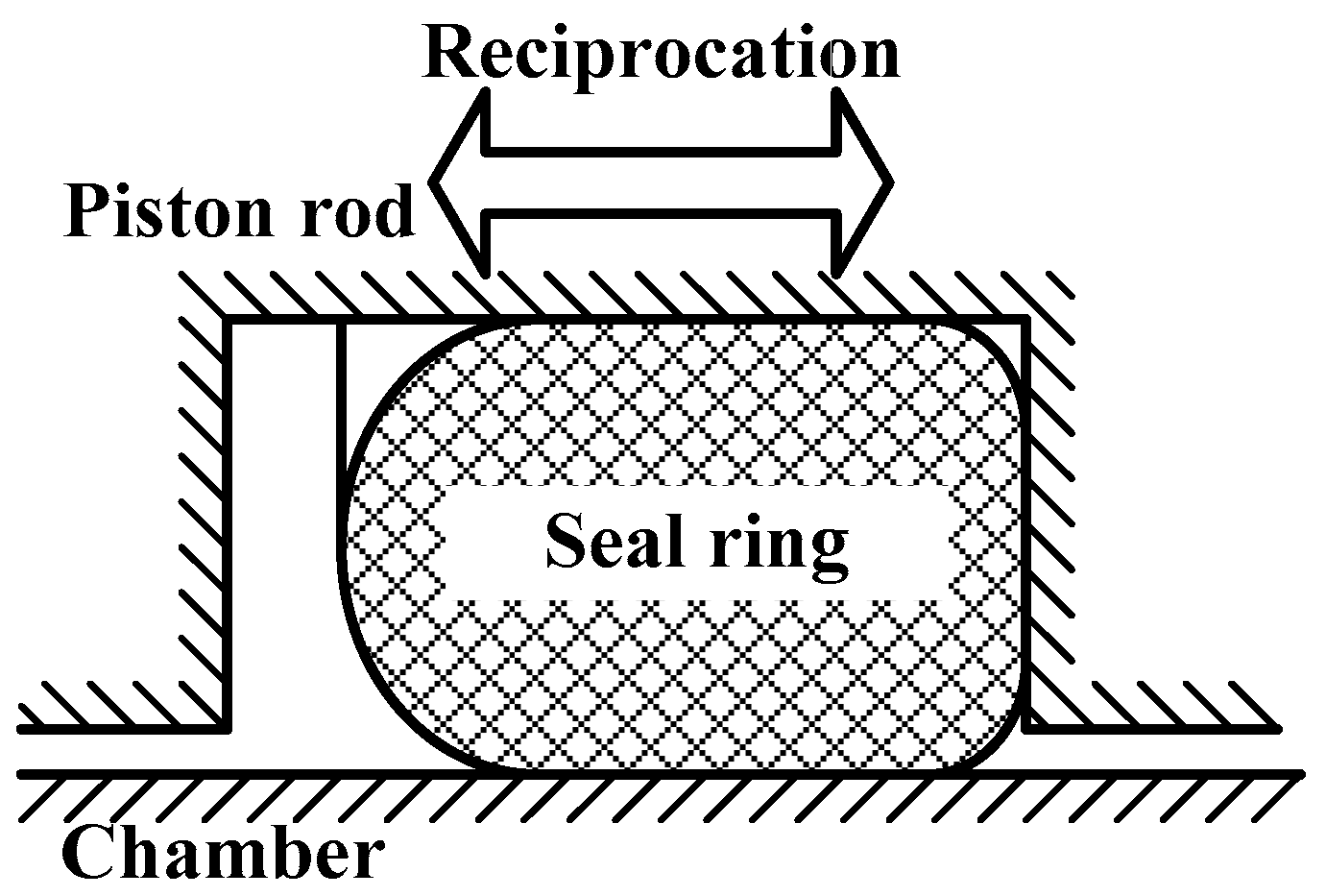
1. Introduction
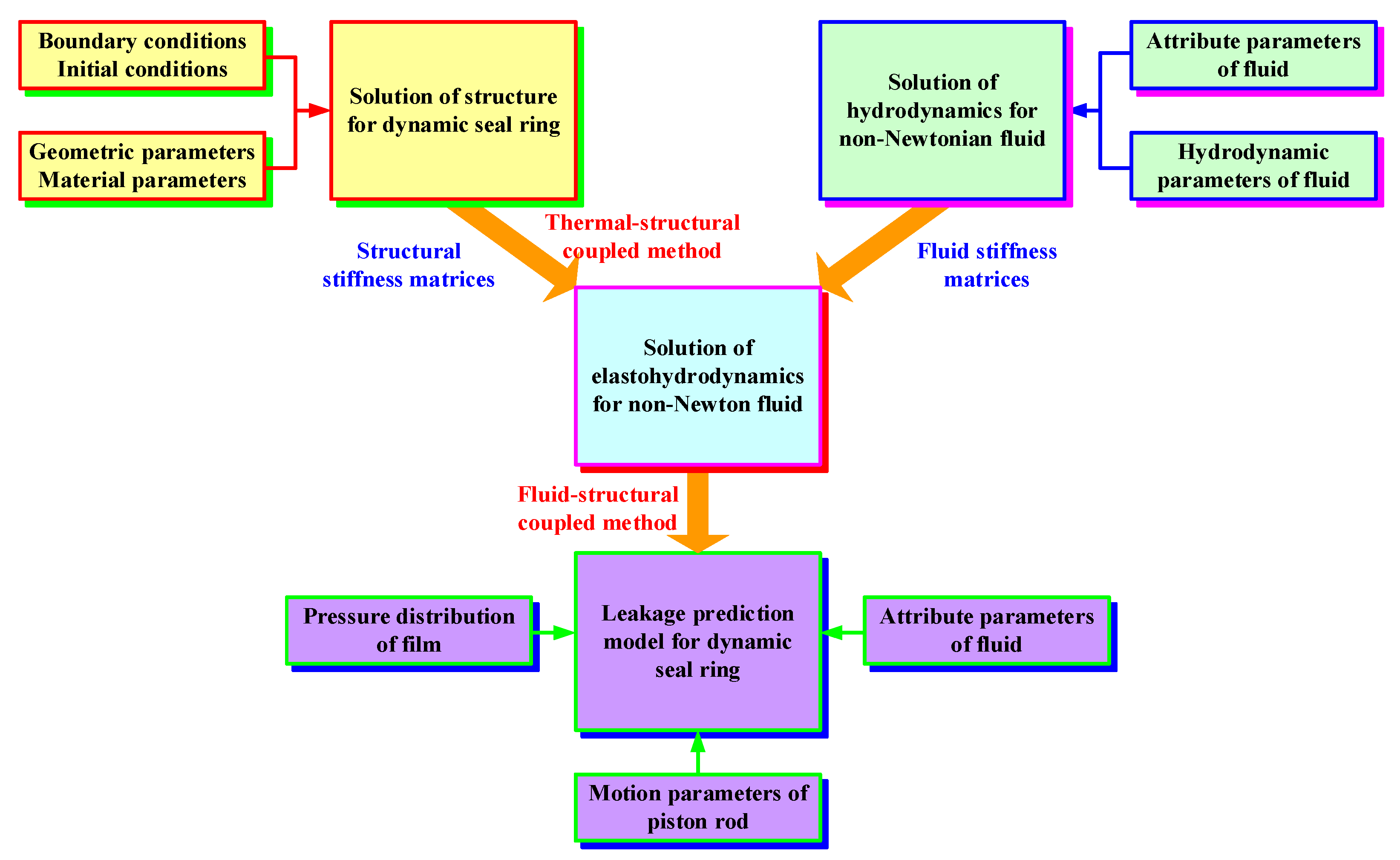
2. Leakage Prediction Calculation Method for Dynamic Seal Ring in Underground Equipment
3. Leakage Prediction Model for Dynamic Seal Ring in Underground Equipment
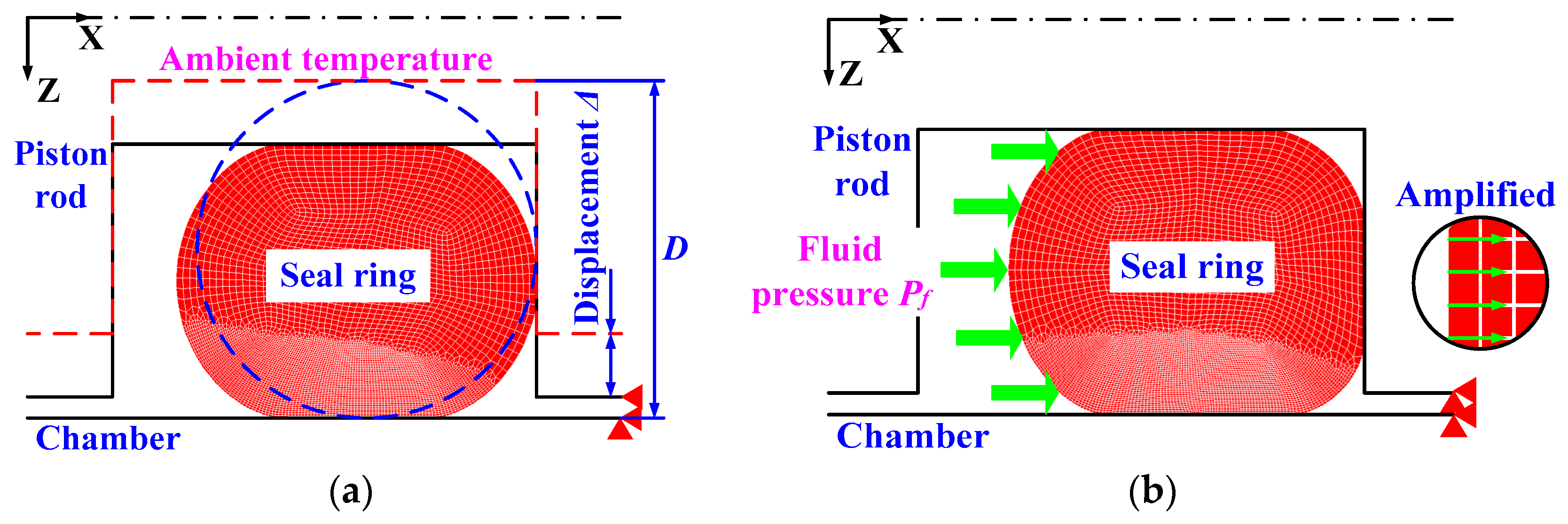
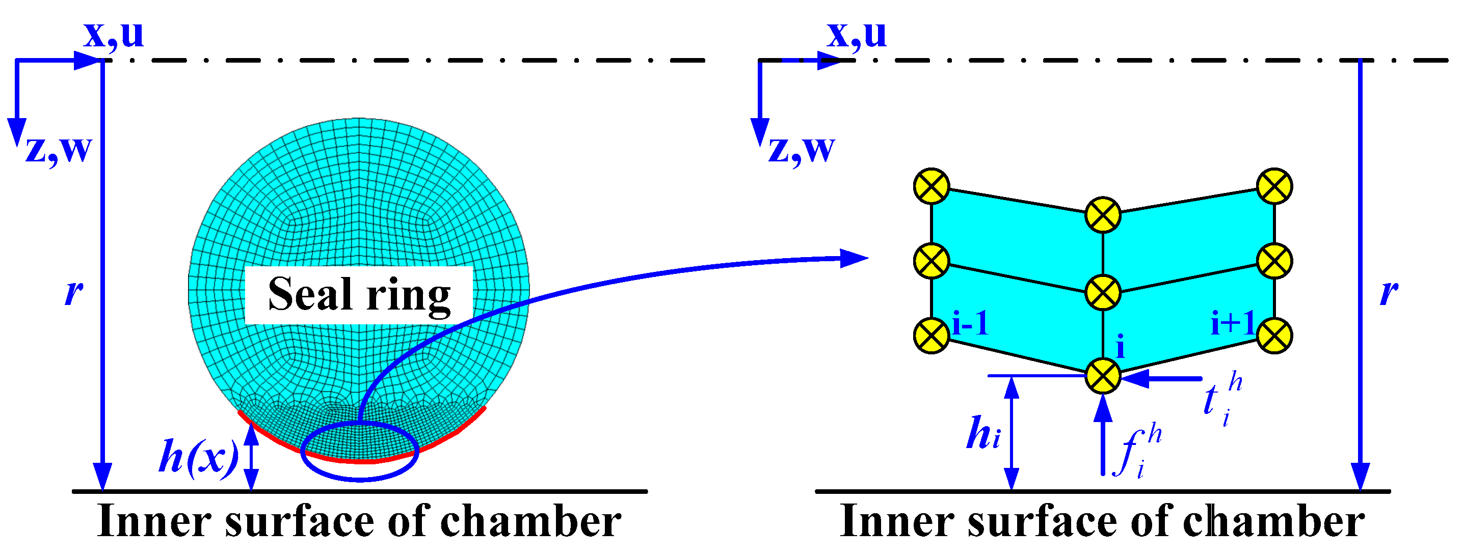
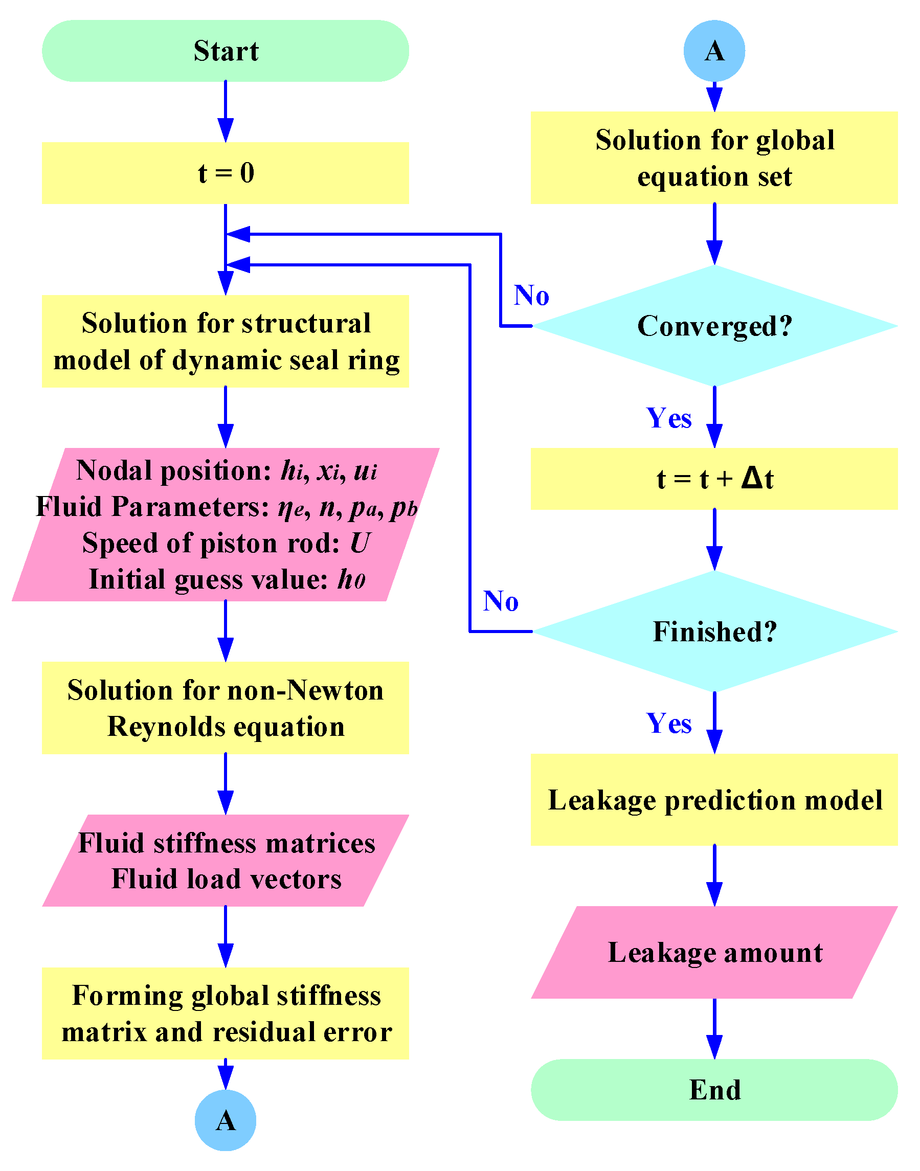
4. Solution of the Structural FE Model for Dynamic Seal Ring
5. Interface Element of Non-Newtonian Fluid
6. Solution for EHD Domain of Non-Newtonian Fluid
6.1. Solution for FE Model
6.2. Stiffness Matrix of Non-Newtonian Fluid Interface Element
7. Development of Leakage Prediction Calculation Method for Dynamic Seal Ring in Underground Equipment
8. Test for Verification and Analysis of Results
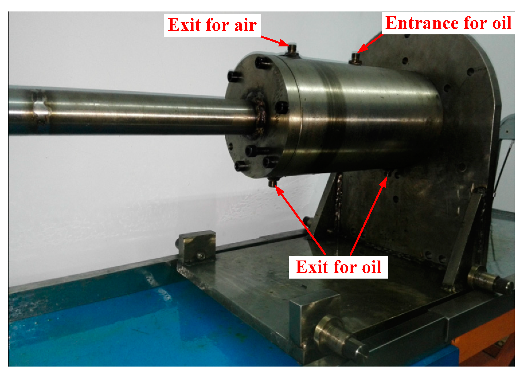
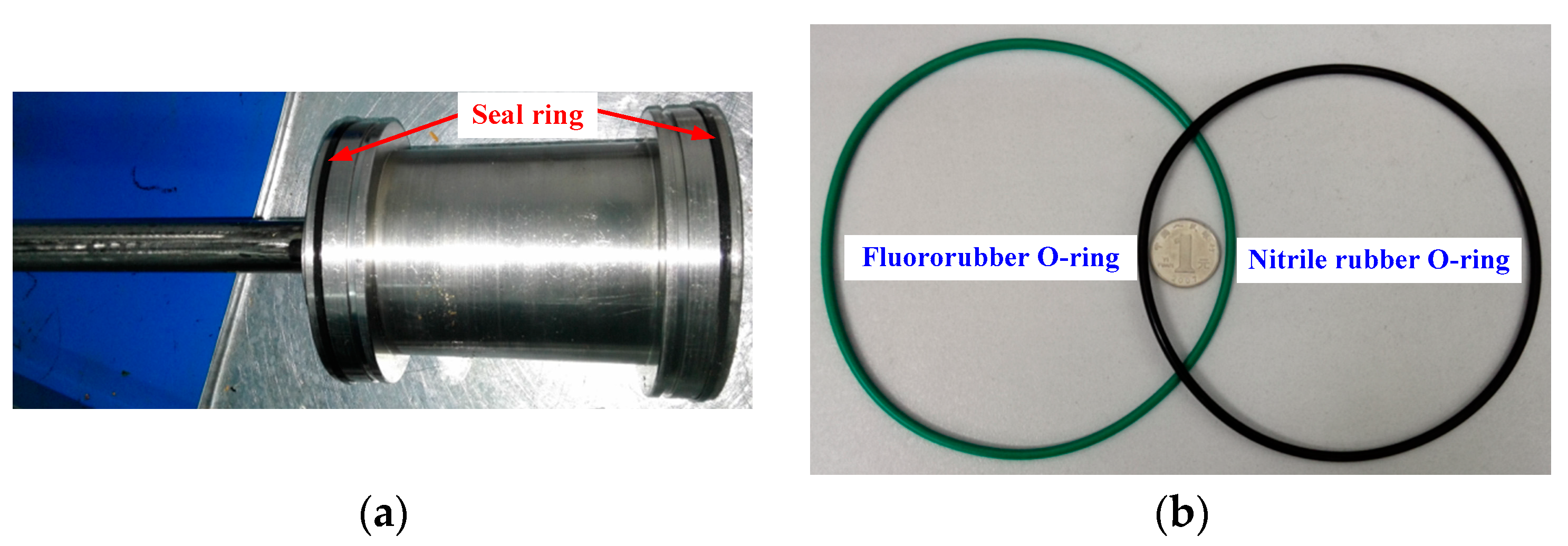
8.1. Test
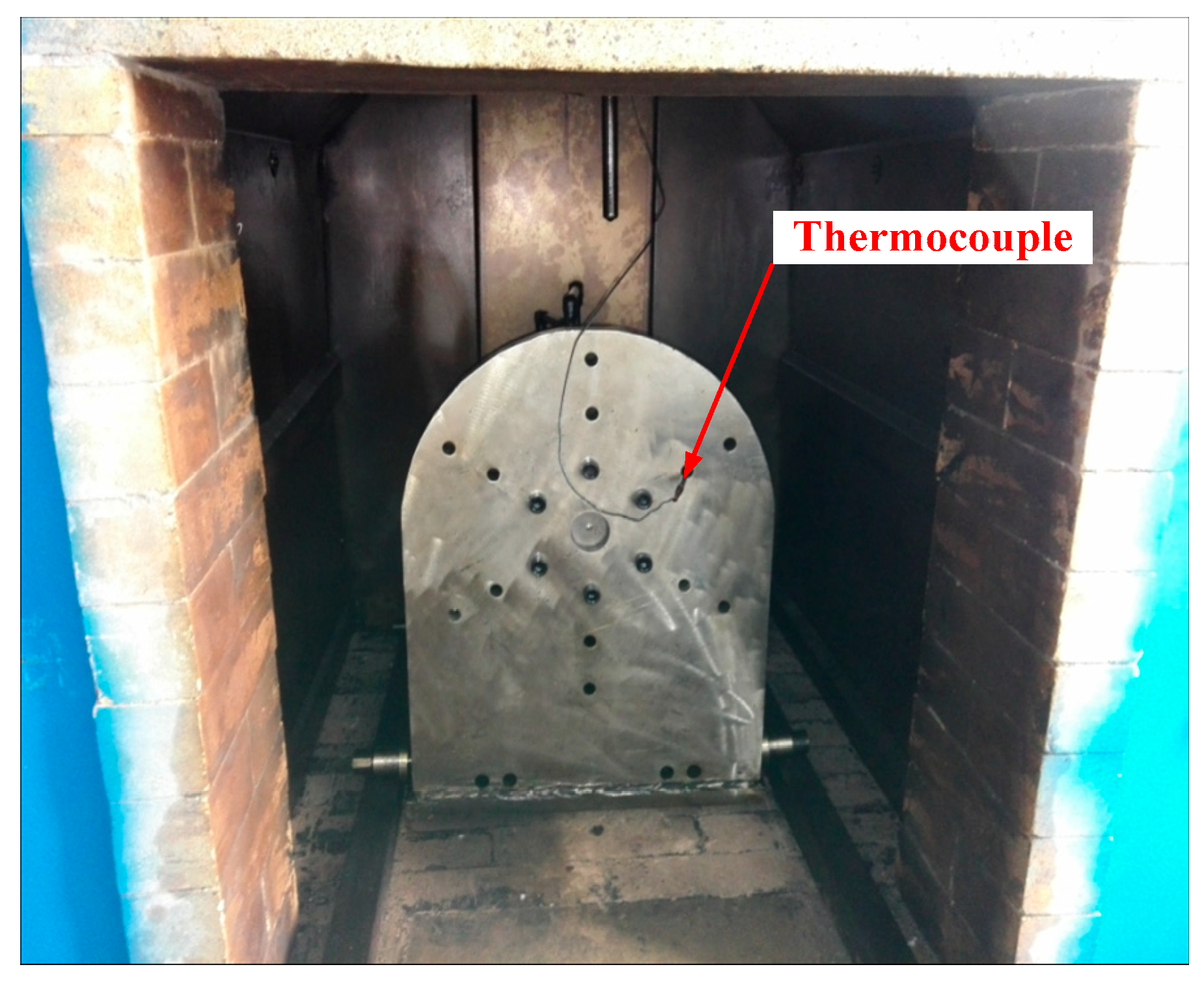
8.1.1. Test for Verification
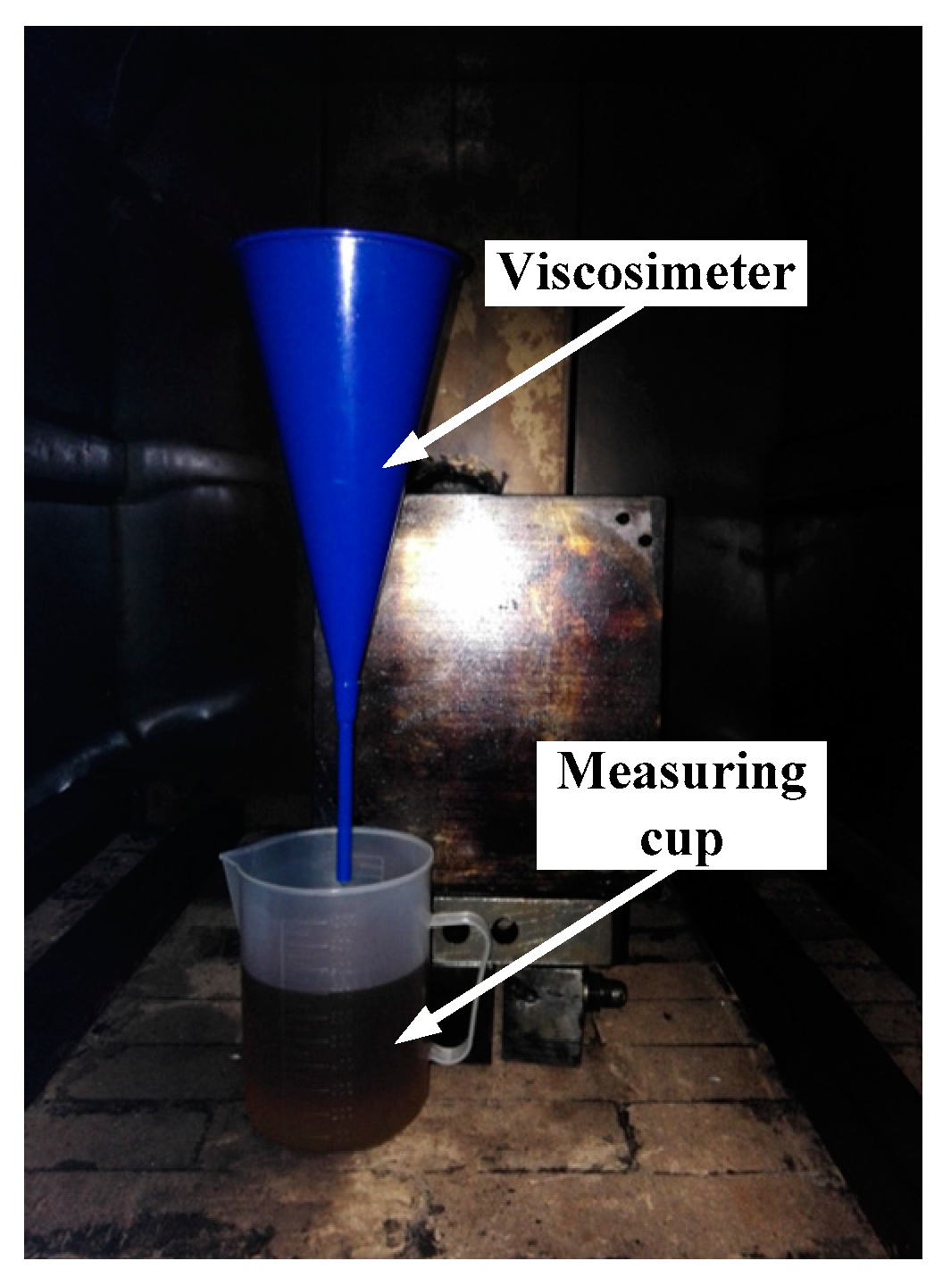
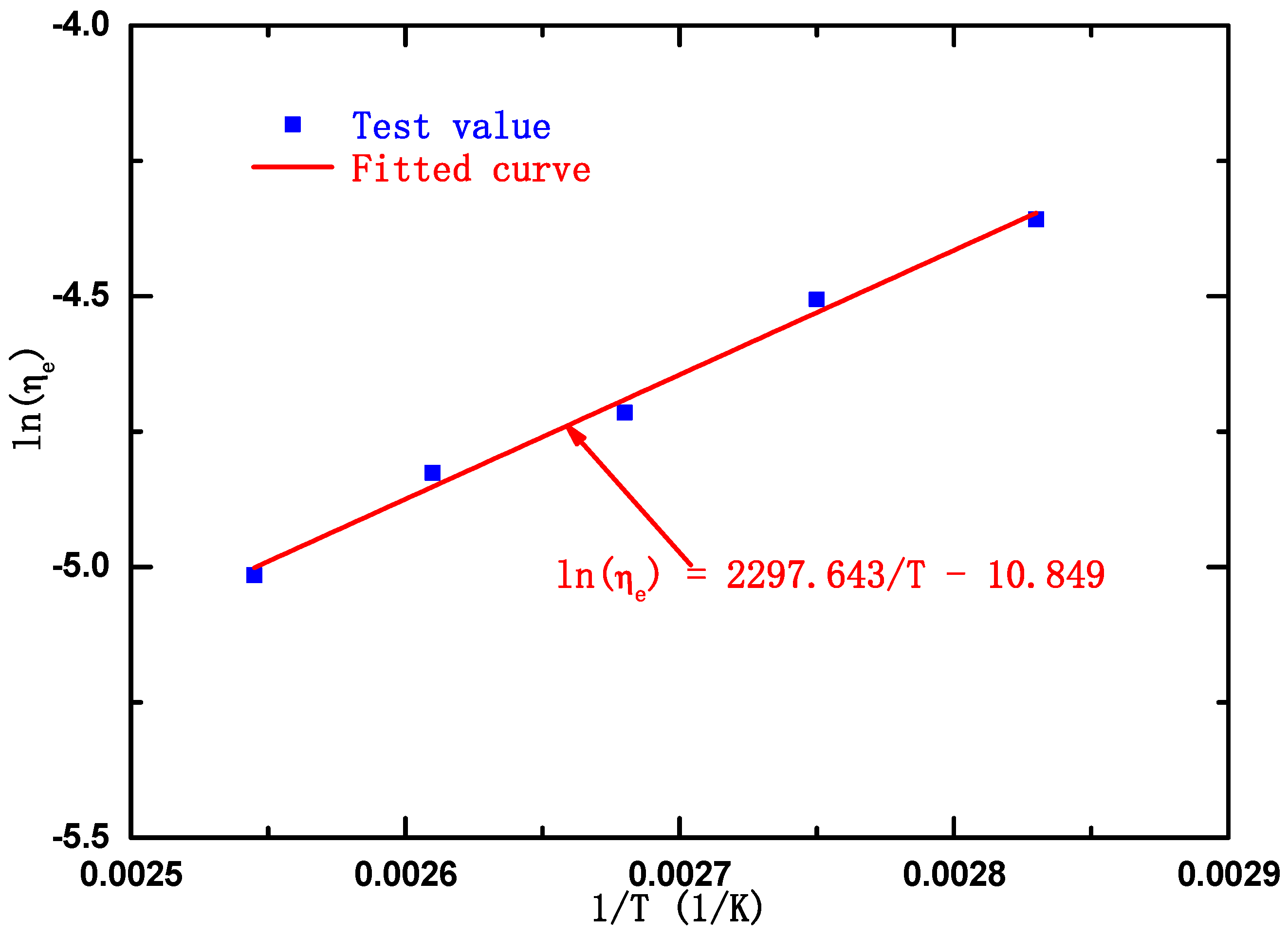
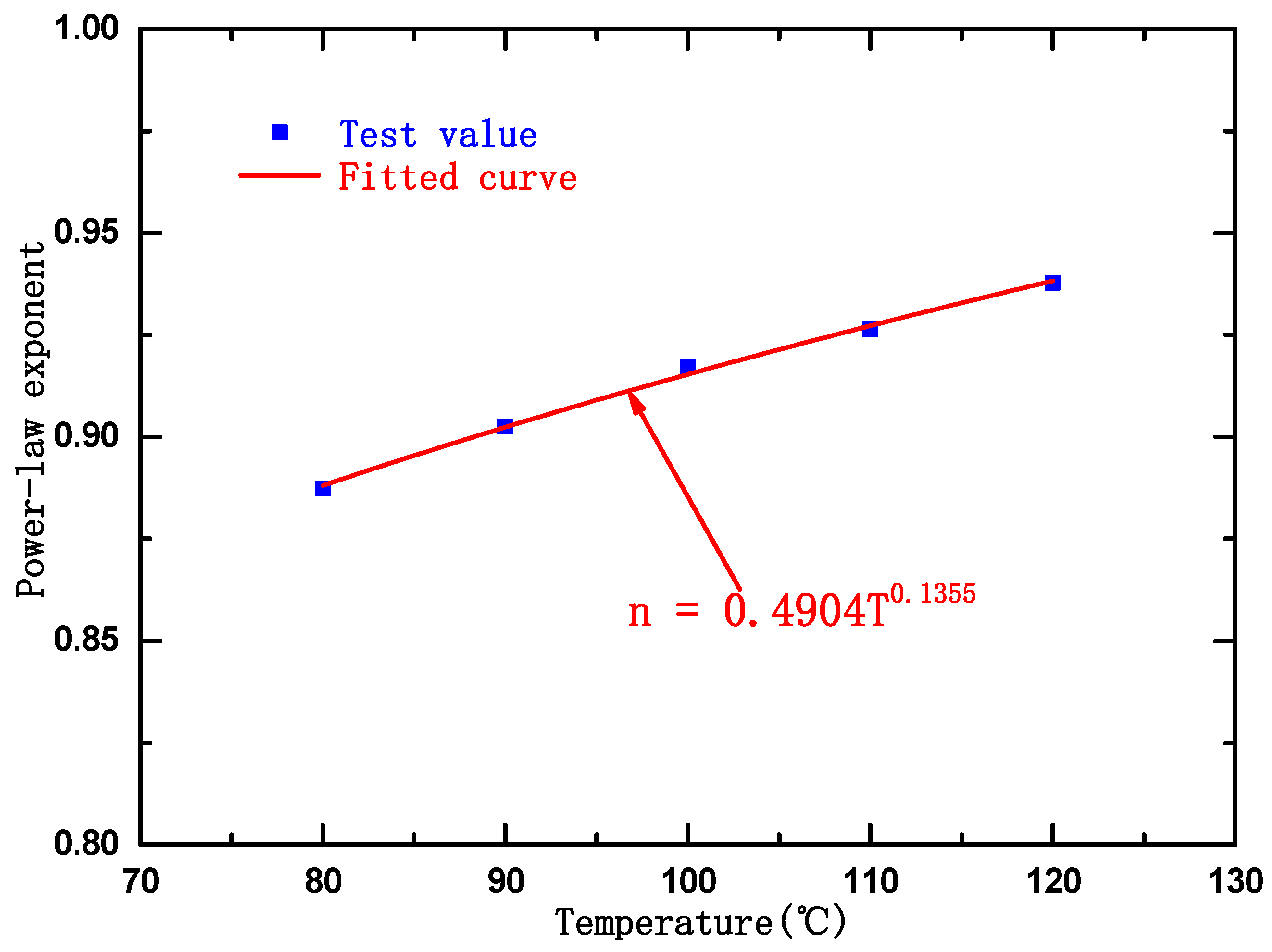
8.1.2. Determination of Non-Newtonian Fluid Parameters
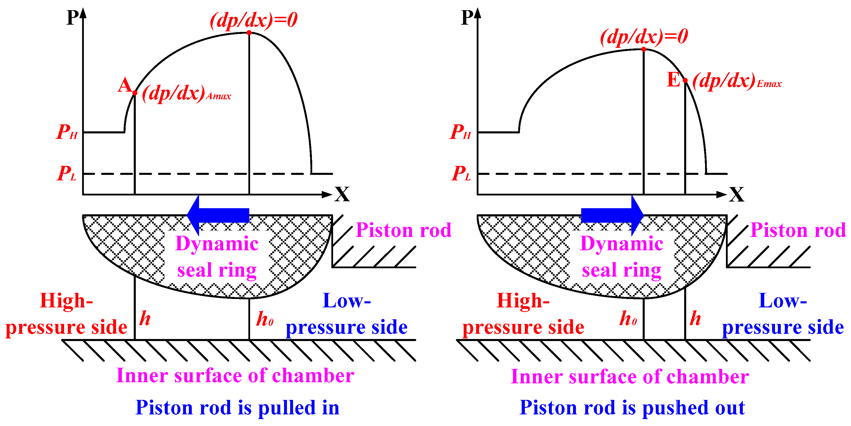
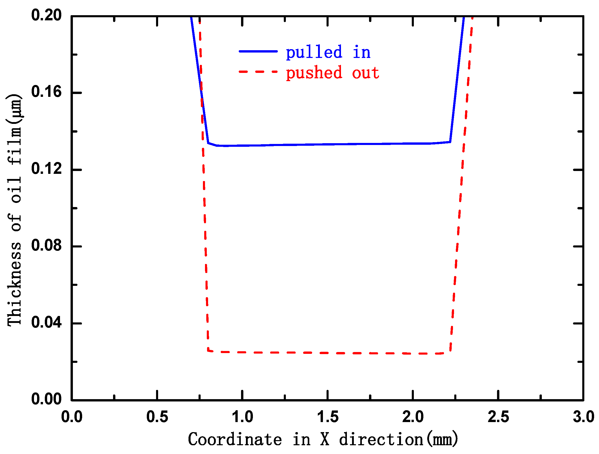
8.2. Hydrodynamic Characteristic of Oil Film in the Sealing Clearance
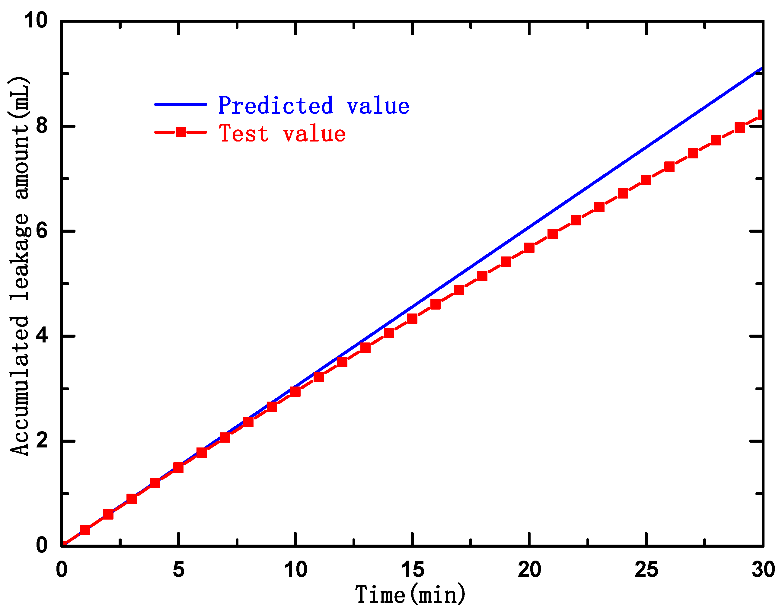
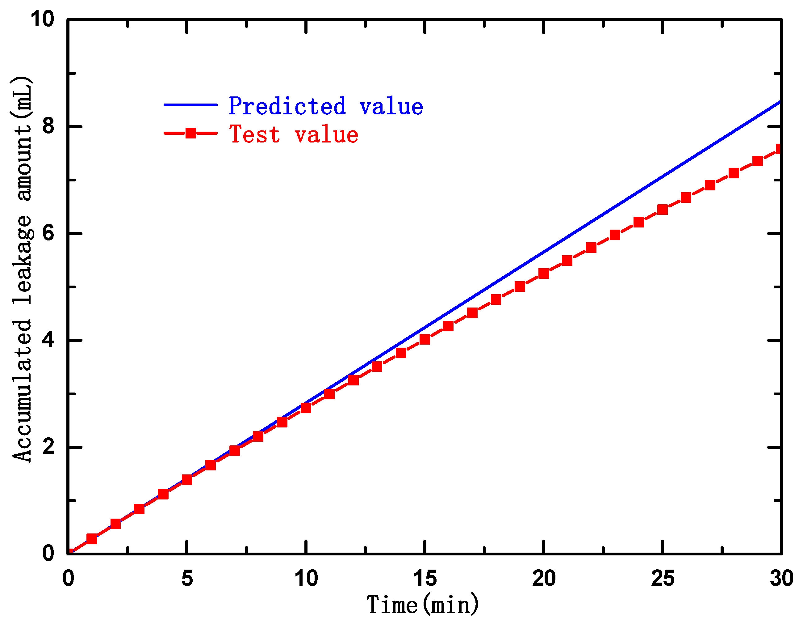
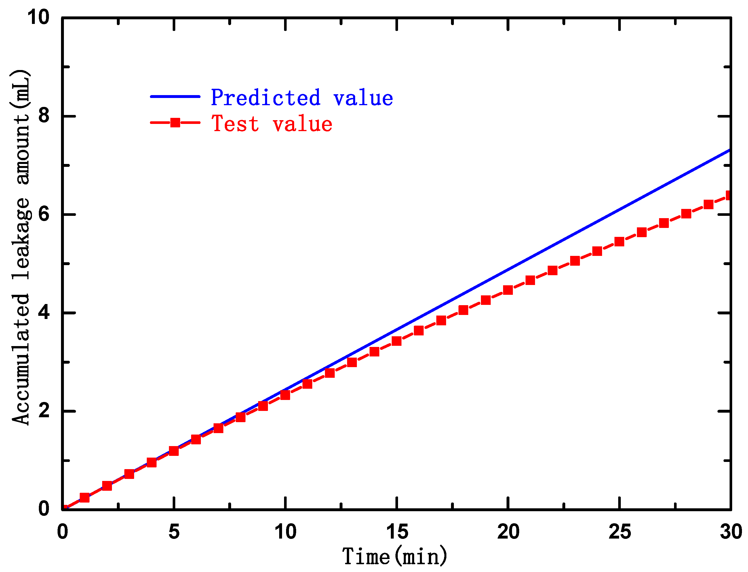
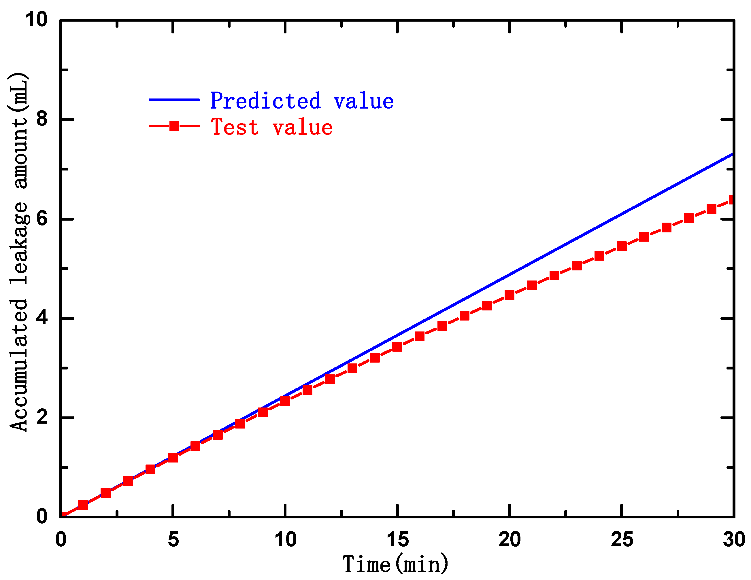
8.3. Comparison and Analysis of the Results
9. Conclusions
- (1)
- A Framework of the method was given;
- (2)
- A leakage prediction model for dynamic seal rings in underground equipment was built. Non-Newtonian fluid interface elements were brought in;
- (3)
- Development of the leakage prediction calculation method was given;
- (4)
- A test was performed to validate the proposed method.
Author Contributions
Funding
Data Availability Statement
Conflicts of Interest
References
- Saychenko, L.; Tananykhin, D.; Ashena, R. Prevention of scale in the downhole equipment and productive reservoir during the oil well operation. J. Appl. Eng. Sci. 2021, 19, 363–368. [Google Scholar] [CrossRef]
- Xie, H.; Konietzky, H.; Zhou, H.W. Special issue “deep mining”. Rock Mech. Rock Eng. 2019, 52, 1415–1416. [Google Scholar] [CrossRef]
- Gao, M.; Xie, J.; Gao, Y.; Wang, W.; Li, C.; Yang, B.; Liu, J.; Xie, H. Mechanical behavior of coal under different mining rates: A case study from laboratory experiments to field testing. Int. J. Min. Sci. Technol. 2021, 31, 825–841. [Google Scholar] [CrossRef]
- Xie, H.P.; Liu, T.; Gao, M.Z.; Chen, L.; Zhou, H.W.; Ju, Y.; Gao, F.; Peng, X.B.; Li, X.J.; Peng, R.D.; et al. Research on in-situ condition preserved coring and testing systems. Pet. Sci. 2021, 18, 1840–1859. [Google Scholar] [CrossRef]
- Zaripova, L.M.; Gabdrakhimov, M.S. A mathematical model of the pulsator for cleaning paraffin deposits of pipe-lines and downhole equipment. J. Phys. Conf. Ser. 2019, 1333, 032095. [Google Scholar] [CrossRef]
- Xie, H.P. Research framework and anticipated results of deep rock mechanics and mining theory. Adv. Eng. Sci. 2017, 49, 1–16. [Google Scholar]
- Gao, M.Z.; Liu, J.J.; Lin, W.M.; Deng, G.; Peng, G.; Li, C.; He, Z. Study on in-situ stress evolution law of ultra-thick coal seam in advance mining. Coal Sci. Technol. 2020, 48, 8. [Google Scholar]
- Gao, M.; Wang, M.; Xie, J.; Gao, Y.; Deng, G.D.; Yang, B.; Wang, F.; Hao, H.; Xie, H. In-situ disturbed mechanical behavior of deep coal rock. J. China Coal Soc. 2020, 45, 2691–2703. [Google Scholar]
- Gao, M.; Xie, J.; Guo, J.; Lu, Y.; He, Z.; Li, C. Fractal evolution and connectivity characteristics of mining-induced crack networks in coal masses at different depths. Geomech. Geophys. Geo-Energy Geo-Resour. 2021, 7, 9. [Google Scholar] [CrossRef]
- Xie, H.; Gao, F.; Ju, Y. Research and development of rock mechanics in deep ground engineering. Chin. J. Rock Mech. Eng. 2015, 34, 2161–2178. [Google Scholar]
- Yin, Q.; Wu, J.; Zhu, C.; He, M.; Meng, Q.; Jing, H. Shear mechanical responses of sandstone exposed to high temperature under constant normal stiffness boundary conditions. Geomech. Geophys. Geo-Energy Geo-Resour. 2021, 7, 35. [Google Scholar] [CrossRef]
- Yin, Q.; Wu, J.; Zhu, C.; Wang, Q.; Zhang, Q.; Jing, H.; Xie, J. The role of multiple heating and water cooling cycles on physical and mechanical responses of granite rocks. Geomech. Geophys. Geo-Energy Geo-Resour. 2021, 7, 69. [Google Scholar] [CrossRef]
- Gao, M.Z.; Zhang, J.G.; Li, S.W.; Wang, M.; Wang, Y.W.; Cui, P.F. Calculating changes in fractal dimension of surface cracks to quantify how the dynamic loading rate affects rock failure in deep mining. J. Cent. South Univ. 2020, 27, 3013–3024. [Google Scholar] [CrossRef]
- Feng, G.; Kang, Y.; Meng, T.; Hu, Y.Q.; Li, X.H. The influence of temperature on mode I fracture toughness and fracture characteristics of sandstone. Rock Mech. Rock Eng. 2017, 50, 2007–2019. [Google Scholar] [CrossRef]
- He, Z.Q.; Chen, L.; Lu, T.; Xie, J. The optimization of pressure controller for deep earth drilling. Therm. Sci. 2019, 23 (Suppl. S3), 877–885. [Google Scholar] [CrossRef]
- Ahmed, S.; Patel, H.; Salehi, S. Numerical modeling and experimental study of elastomer seal assembly in downhole wellbore equipment: Effect of material and chemical swelling. Polym. Test. 2020, 89, 106608. [Google Scholar] [CrossRef]
- Zhu, X.; Jing, Y. Analysis of Main Influence Factors for Slip Ring Combined Rotating Seals Based on 3D Contact. China Mech. Eng. 2017, 28, 1548. [Google Scholar]
- Guo, Y.; Wu, L.; Xu, H.; Zeng, L.; Zhan, C. Analysis of dynamic sealing performance of Glyd ring and optimization of sealing parameters. Lubric. Eng. 2021, 46, 17–25. [Google Scholar]
- Zhao, L.; Suo, S.F.; Shi, J.W. Design and research of high-pressure rotary combined seal test device. Lubric. Eng. 2020, 45, 12. [Google Scholar]
- Salant, R.F.; Maser, N.; Yang, B. Numerical model of a reciprocating hydraulic rod seal. Int. Jt. Tribol. Conf. 2006, 42592, 577–583. [Google Scholar]
- Nikas, G.K.; Sayles, R.S. Computational model of tandem rectangular elastomeric seals for reciprocating motion. Tribol. Int. 2006, 39, 622–634. [Google Scholar] [CrossRef]
- Chen, B.; Yang, X.; Tu, Q. The sealing performance of cap-shape ring combined seal. Lubric. Eng. 2019, 44, 92–98. [Google Scholar]
- Blasiak, S.; Laski, P.A.; Takosoglu, J.E. Parametric analysis of heat transfer in non-contacting face seals. Int. J. Heat Mass Transf. 2013, 57, 22–31. [Google Scholar] [CrossRef]
- Mo, L.; Wang, J.; Guan, X.Q. Analysis of dynamic sealing characteristics of O-ring in petroleum machinery. Chin. Petrol. Mach 2014, 42, 103–107. [Google Scholar]
- Sukumar, T.; Subramanian, M.; Subramaniyan, S.K.; Subramanian, N. Design and Optimization of Lip Seal for Air Braking System; SAE Technical Paper; SAE International: Warrendale, PA, USA, 2015. [Google Scholar]
- Chen, H.L.; Liu, J.F.; Ren, K.T.; Li, T.; Fu, J.; Zou, Q.; Yin, Y.X. Optimization of upstream pumping mechanical seal based on response surface method. J. Drain. Irrig. Mach. Eng. 2016, 34, 232–237. [Google Scholar]
- Ahmed, S.; Salehi, S.; Ezeakacha, C.; Teodoriu, C. Experimental investigation of elastomers in downhole seal elements: Implications for safety. Polym. Test. 2019, 76, 350–364. [Google Scholar] [CrossRef]
- Gang, X.; Yong, L.; Jiu-Shun, C.; Li-Yu, D. Rheological property of Aqueous Partially Hydrolyzed Polyacrylamide Solution. Chi-Nese J. Appl. Chem. 2000, 17, 72–74. [Google Scholar]
- Li, X.; Li, C.; Shu, A.; Xie, Y. Measuring rheological parameters of power law fluid by funnel viscometer. Nat. Gas Ind. 2003, 23, 47–50. [Google Scholar]
- Li, Y.; Zhang, K.; Wang, Y.Z.; Wang, L.N. Apparent viscosity model of power law fluid flow in heavy oil wells. Shiyou Kantan Yu Kaifa (Pet. Explor. Dev.) 2007, 34, 616–621. [Google Scholar]
- Schmidt, T.; André, M.; Poll, G. A transient 2D-finite-element approach for the simulation of mixed lubrication effects of recip-rocating hydraulic rod seals. Tribol. Int. 2010, 43, 1775–1785. [Google Scholar] [CrossRef]


| h4~h3 | h3~h2 | h2~h1 | |||||||
|---|---|---|---|---|---|---|---|---|---|
| ts | tfa | tf | ts | tfa | tf | ts | tfa | tf | |
| 1 | 12.0 s | 6.0 s | 6.0 s | 9.1 s | 4.2 s | 4.9 s | 6.2 s | 3.0 s | 3.2 s |
| 2 | 11.6 s | 6.0 s | 5.6 s | 8.8 s | 4.2 s | 4.6 s | 6.7 s | 3.0 s | 3.7 s |
| 3 | 12.2 s | 6.0 s | 6.2 s | 8.7 s | 4.2 s | 4.5 s | 6.3 s | 3.0 s | 3.3 s |
| 4 | 11.8 s | 6.0 s | 5.8 s | 8.6 s | 4.2 s | 4.4 s | 6.8 s | 3.0 s | 3.8 s |
| Average | 11.9 s | 6.0 s | 5.9 s | 8.8 s | 4.2 s | 4.6 s | 6.5 s | 3.0 s | 3.5 s |
| h4~h3 | h3~h2 | h2~h1 | |||||||
|---|---|---|---|---|---|---|---|---|---|
| ts | tfa | tf | ts | tfa | tf | ts | tfa | tf | |
| 1 | 10.7 s | 6.0 s | 4.7 s | 7.8 s | 4.2 s | 3.6 s | 5.9 s | 3.0 s | 2.7 s |
| 2 | 10.8 s | 6.0 s | 4.8 s | 8.1 s | 4.2 s | 3.9 s | 6.0 s | 3.0 s | 3.0 s |
| 3 | 10.7 s | 6.0 s | 4.7 s | 8.0 s | 4.2 s | 3.8 s | 5.6 s | 3.0 s | 2.6 s |
| 4 | 11.0 s | 6.0 s | 5.0 s | 7.7 s | 4.2 s | 3.5 s | 5.9 s | 3.0 s | 2.9 s |
| Average | 10.8 s | 6.0 s | 4.8 s | 7.9 s | 4.2 s | 3.7 s | 5..8 s | 3.0 s | 2.8 s |
| Parameters | Value |
|---|---|
| Elasticity modulus of nitrile rubber, E | 6.10 MPa |
| Poisson’s ratio of nitrile rubber, ν | 0.499 |
| Parameter of Mooney-Rivlin model (353K), C10 | 0.813 MPa |
| Parameter of Mooney-Rivlin model (353K), C01 | 0.203 MPa |
| Coefficient of thermal expansion of nitrile rubber, α | 1.6 × 10⁻⁴/K |
| Ambient temperature, T | 353 K |
Disclaimer/Publisher’s Note: The statements, opinions and data contained in all publications are solely those of the individual author(s) and contributor(s) and not of MDPI and/or the editor(s). MDPI and/or the editor(s) disclaim responsibility for any injury to people or property resulting from any ideas, methods, instructions or products referred to in the content. |
© 2023 by the authors. Licensee MDPI, Basel, Switzerland. This article is an open access article distributed under the terms and conditions of the Creative Commons Attribution (CC BY) license (https://creativecommons.org/licenses/by/4.0/).
Share and Cite
Xu, X.; Li, X.; Wang, F.; Xia, C. Research on Leakage Prediction Calculation Method for Dynamic Seal Ring in Underground Equipment. Lubricants 2023, 11, 181. https://doi.org/10.3390/lubricants11040181
Xu X, Li X, Wang F, Xia C. Research on Leakage Prediction Calculation Method for Dynamic Seal Ring in Underground Equipment. Lubricants. 2023; 11(4):181. https://doi.org/10.3390/lubricants11040181
Chicago/Turabian StyleXu, Xiaohui, Xin Li, Fengtao Wang, and Chunmiao Xia. 2023. "Research on Leakage Prediction Calculation Method for Dynamic Seal Ring in Underground Equipment" Lubricants 11, no. 4: 181. https://doi.org/10.3390/lubricants11040181
APA StyleXu, X., Li, X., Wang, F., & Xia, C. (2023). Research on Leakage Prediction Calculation Method for Dynamic Seal Ring in Underground Equipment. Lubricants, 11(4), 181. https://doi.org/10.3390/lubricants11040181