Sustainable Vegetable Oil-Based Minimum Quantity Lubrication Assisted Machining of AZ91 Magnesium Alloy: A Grey Relational Analysis-Based Study
Abstract
1. Introduction
2. Materials and Methods
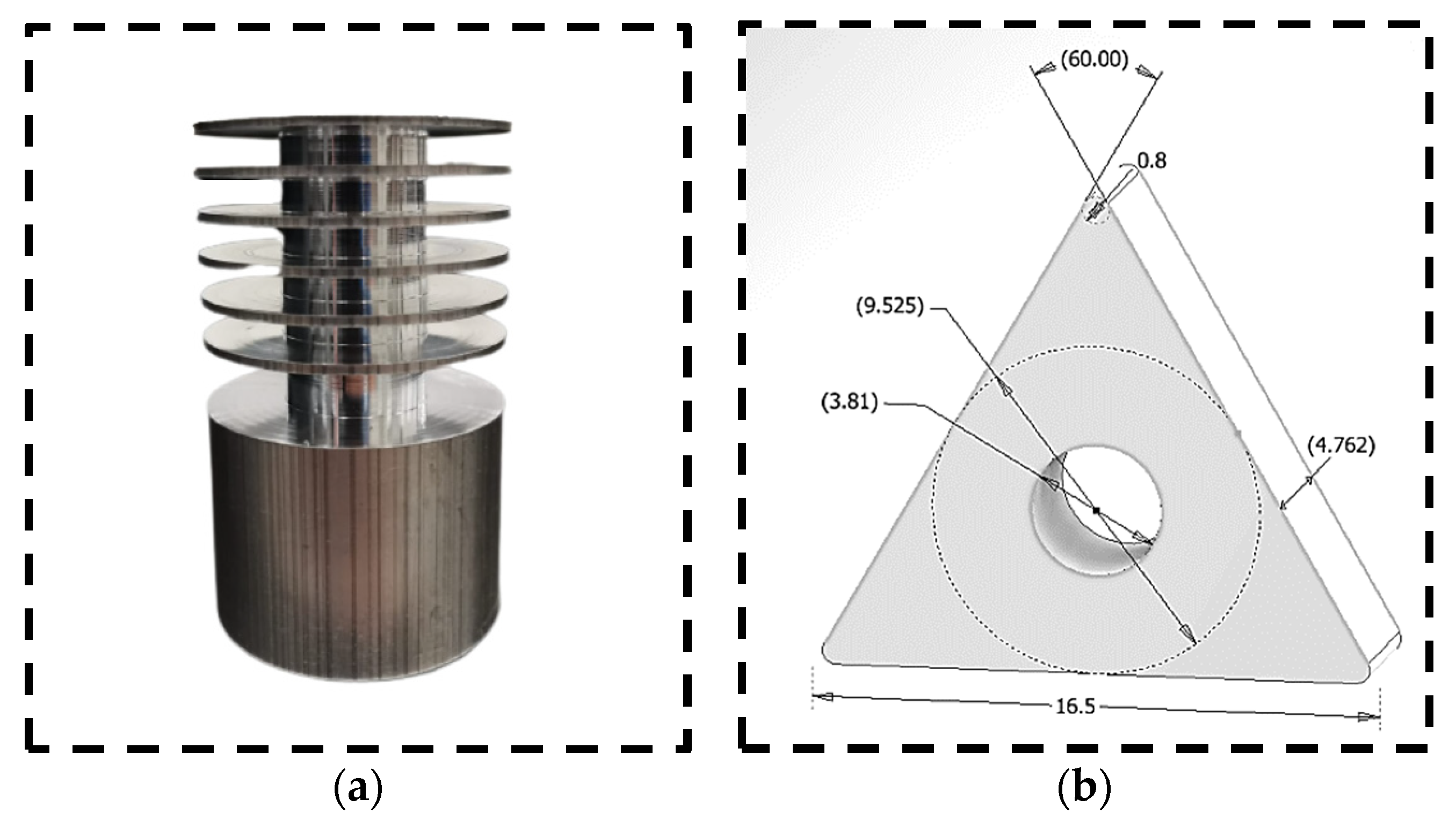
2.1. Tool and Material Information
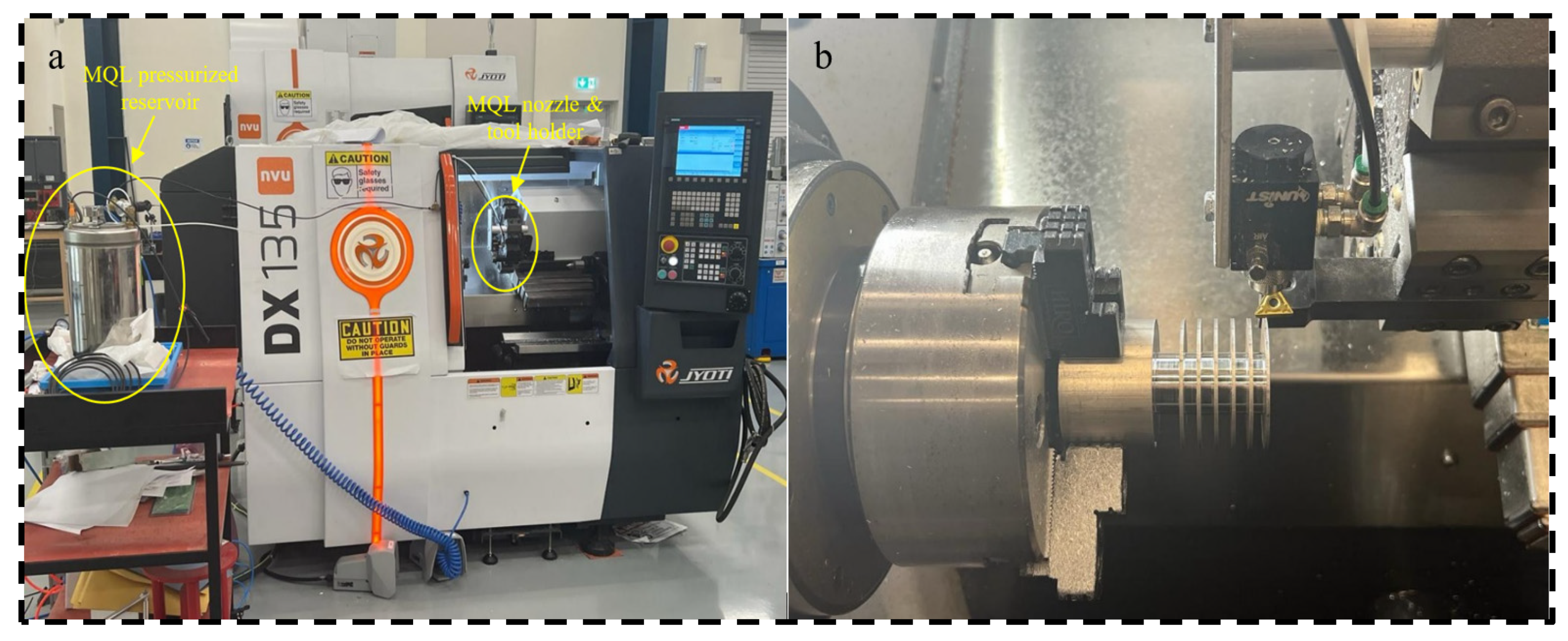
2.2. Machining Set-Up
2.3. Full Factorial Experimental Design
3. Results and Discussion
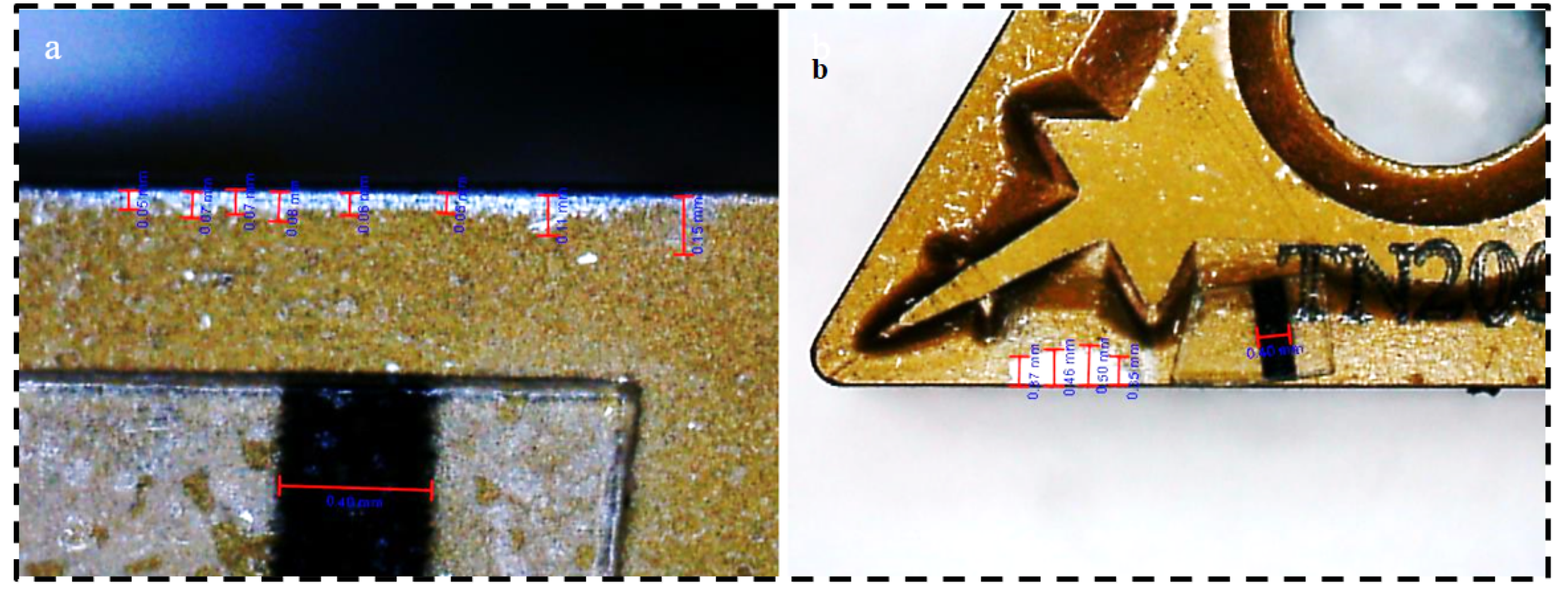
3.1. Data Processing and Parameter Computation
3.2. Full Factorial Design Based Data Analysis
3.3. Grey Relational Analysis
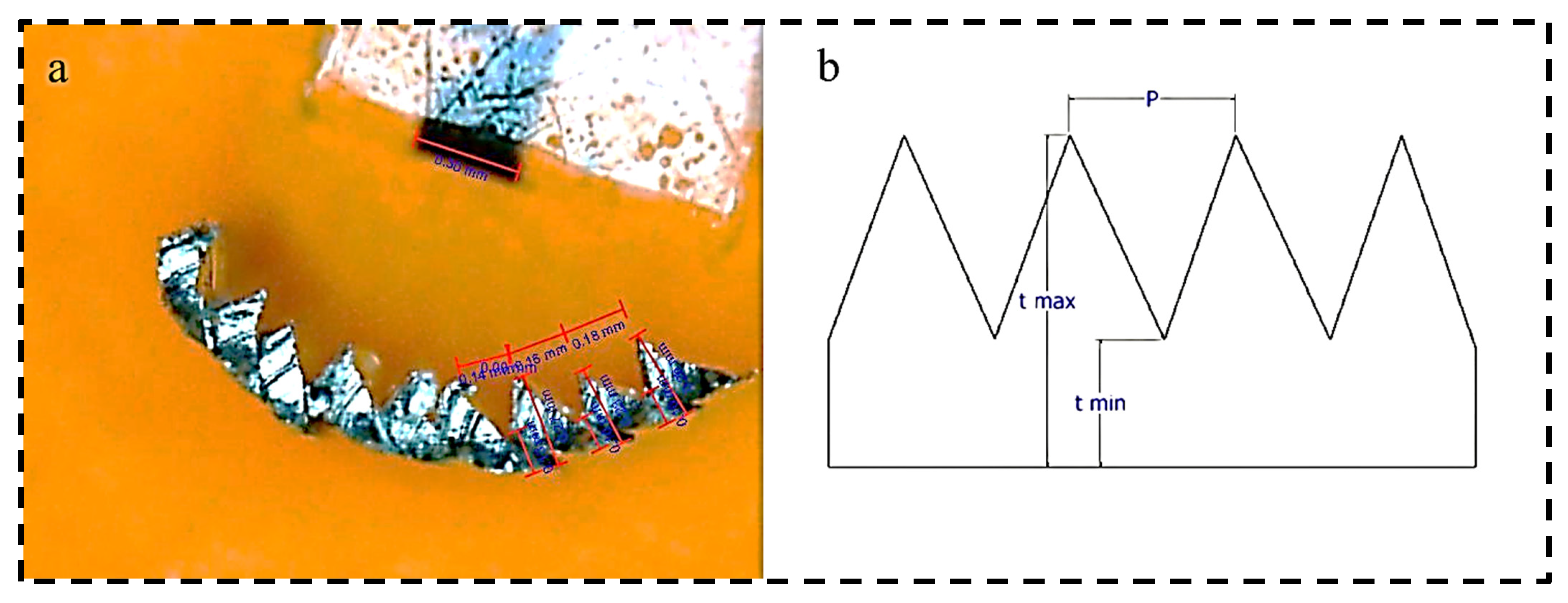
3.4. Chip Segmentation Ratio
4. Conclusions and Future Suggestions
- The optimal control parameters predicted and experimentally confirmed were an MQL flow rate of 40 mL/h, cutting speed of 300 m/min, and feed rate of 0.3 mm/rev;
- The usage of said optimal parameters results in a grey relational grade improvement of 0.2675 in comparison to the referenced first experimental run;
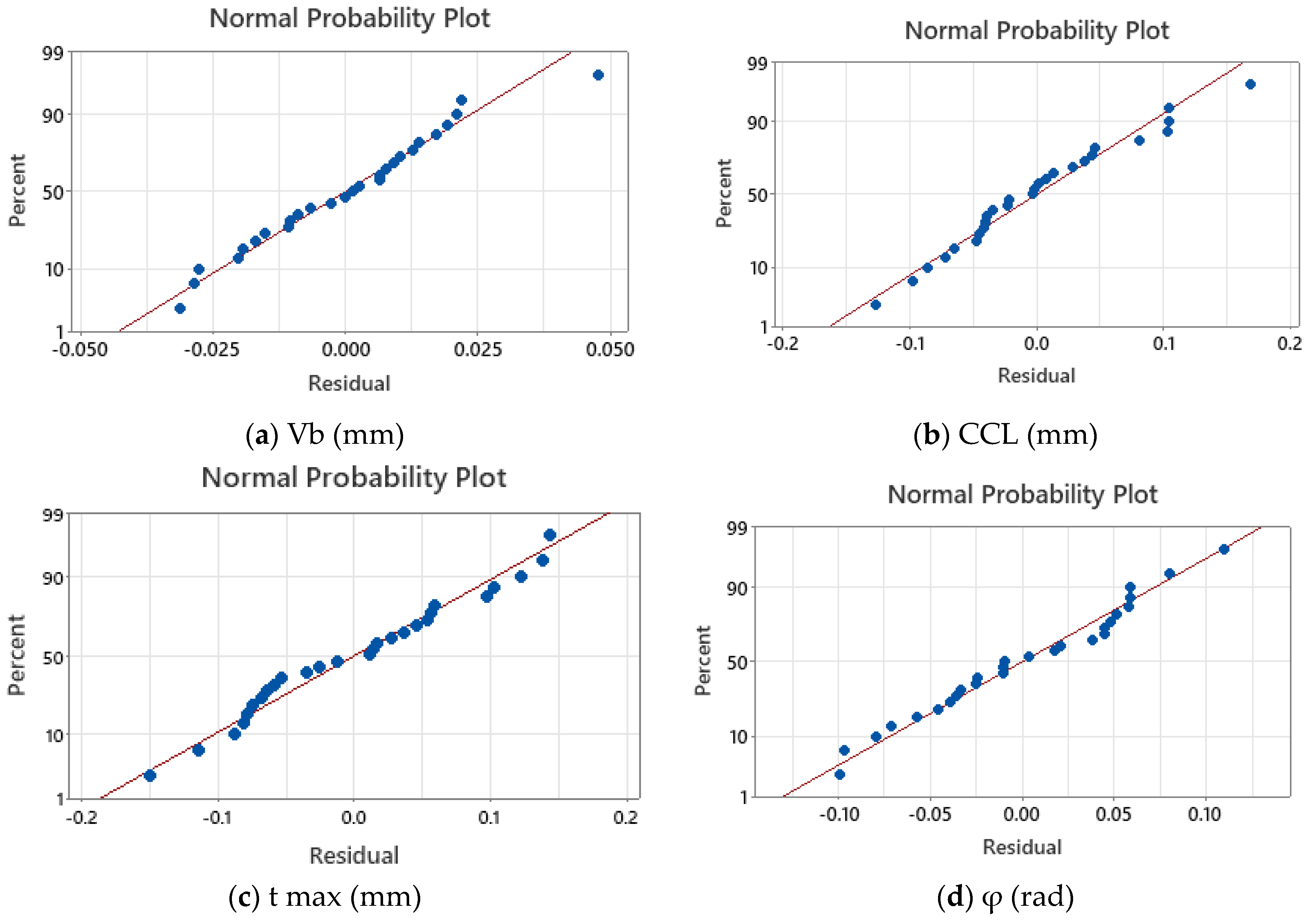
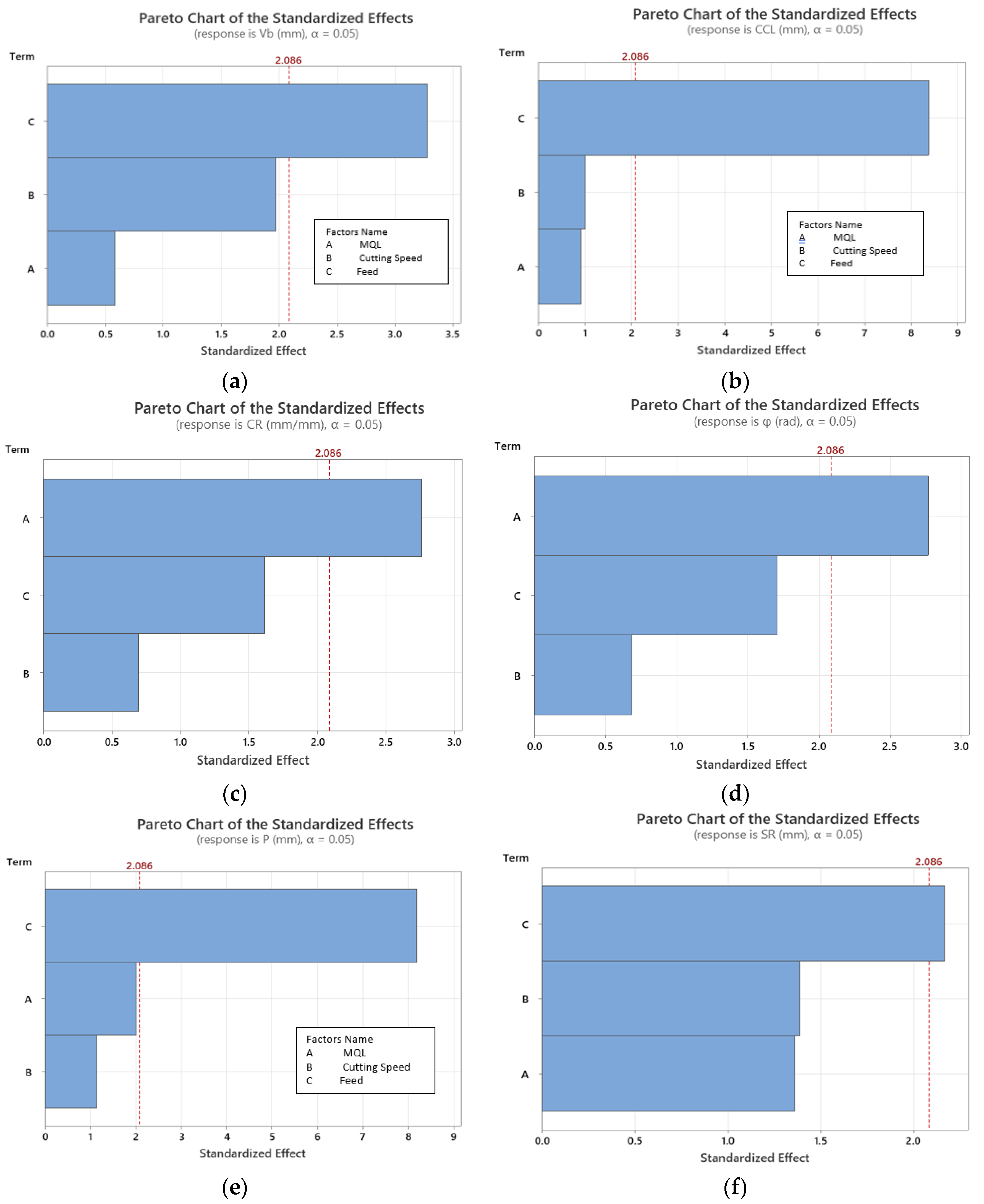
- Using the variance analysis conducted by the Minitab program, the MQL was regarded as one of the critical variables in the optimization process with a contribution of 20%. This signifies the important role of the cooling and lubrication effects provided by the usage of the MQL in reducing tribological friction forces and cutting temperatures;
- The third level interaction of the MQL with the cutting speed and feed, and the second level interaction of the MQL flow rate with the cutting speed were found to be significant contributing factors with a contribution of 31.56% and 24.23%, respectively;
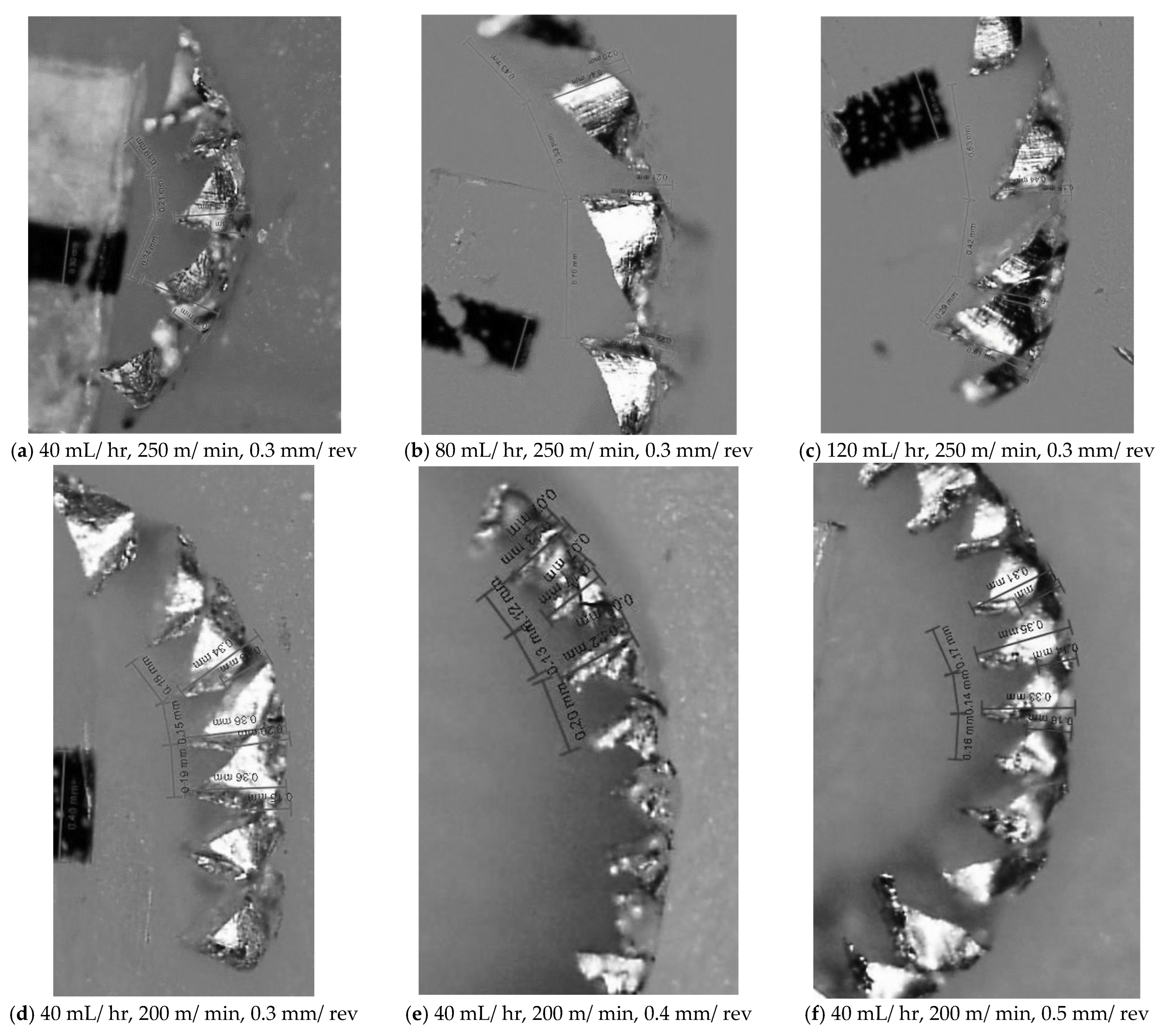
- The main individual contributor to the segmentation ratio was found to be the MQL flow rate with a percentage contribution of 19.68%. This is linked with the improved heat transfer as the MQL flow rate increased;
- For a greater assessment of the application of vegetable oil-based cutting fluids (VCFs), it is recommended that further output responses, such as surface quality, microhardness, and microstructure, are investigated during the high-speed orthogonal cutting of magnesium alloys to allow for the proper assessment of their feasibility and applicability.
Author Contributions
Funding
Data Availability Statement
Conflicts of Interest
References
- Gándara, M.J.F. Recent growing demand for magnesium in the automotive industry recent growing demand for magnesium in the automotive industry. Mater. Technol. 2011, 45, 633–637. [Google Scholar]
- Overview Magnesium for Automotive Applications. Available online: www.tms.org/jom.html (accessed on 10 September 2022).
- Ramalingam, V.V.; Ramasamy, P.; Das Kovukkal, M.; Myilsamy, G. Research and Development in Magnesium Alloys for Industrial and Biomedical Applications: A Review. Met. Mater. Int. 2020, 26, 409–430. [Google Scholar] [CrossRef]
- Li, N.; Zheng, Y. Novel Magnesium Alloys Developed for Biomedical Application: A Review. J. Mater. Sci. Technol. 2013, 29, 489–502. [Google Scholar] [CrossRef]
- Wan, Y.; Xiong, G.; Luo, H.; He, F.; Huang, Y.; Zhou, X. Preparation and characterization of a new biomedical magnesium-calcium alloy. Mater. Des. 2008, 29, 2034–2037. [Google Scholar] [CrossRef]
- Ostrovsky, I.; Henn, Y. Present state and future of magnesium application in aerospace industry. In Proceedings of the International Conference “New Challenges in Aeronautics” ASTEC, Moscow, Russia, 19–22 August 2007; Volume 7, pp. 19–22. [Google Scholar]
- Nadanasabapathi, S.; Viswanathan, R.; Sivashankar, N.; Chandrakumar, S.; Karthik, R. Improving corrosion resistance of magnesium alloy for aerospace applications. Int. J. Mech. Prod. 2019, 9, 769–774. Available online: http://www.tjprc.org/publishpapers/2-67-1557740616-86IJMPERDJUN201986.pdf (accessed on 10 September 2022).
- Wang, M.; Xiao, D.; Liu, W. Effect of Si addition on microstructure and properties of magnesium alloys with high Al and Zn contents. Vacuum 2017, 141, 144–151. [Google Scholar] [CrossRef]
- Jayasathyakawin, S.; Ravichandran, M.; Baskar, N.; Chairman, C.A.; Balasundaram, R. Mechanical properties and applications of Magnesium alloy—Review. Mater. Today Proc. 2020, 27, 909–913. [Google Scholar] [CrossRef]
- Chen, J.; Tan, L.; Yu, X.; Etim, I.P.; Ibrahim, M.; Yang, K. Mechanical properties of magnesium alloys for medical application: A review. J. Mech. Behav. Biomed. Mater. 2018, 87, 68–79. [Google Scholar] [CrossRef] [PubMed]
- Guo, S.; Liu, R.; Jiang, X.; Zhang, H.; Zhang, D.; Wang, J.; Pan, F. Statistical Analysis on the Mechanical Properties of Magnesium Alloys. Materials 2017, 10, 1271. [Google Scholar] [CrossRef]
- Catherine, L.D.K.; Hamid, D.A. Mechanical Properties and Machinability of Magnesium Alloy AZ31 and AZ91—A Comparative Review. IOP Conf. Ser. Mater. Sci. Eng. 2021, 1062, 012054. [Google Scholar] [CrossRef]
- Viswanathan, R.; Ramesh, S.; Maniraj, S.; Subburam, V. Measurement and multi-response optimization of turning parameters for magnesium alloy using hybrid combination of Taguchi-GRA-PCA technique. Meas. J. Int. Meas. Confed. 2020, 159, 107800. [Google Scholar] [CrossRef]
- Shi, K.; Zhang, D.; Ren, J.; Yao, C.; Huang, X. Effect of cutting parameters on machinability characteristics in milling of magnesium alloy with carbide tool. Adv. Mech. Eng. 2016, 8, 1687814016628392. [Google Scholar] [CrossRef]
- Ramesh, S.; Viswanathan, R.; Ambika, S. Measurement and optimization of surface roughness and tool wear via grey relational analysis, TOPSIS and RSA techniques. Meas. J. Int. Meas. Confed. 2016, 78, 63–72. [Google Scholar] [CrossRef]
- Tönshoff, H.; Winkler, J. The influence of tool coatings in machining of magnesium. Surf. Coat. Technol. 1997, 94-95, 610–616. [Google Scholar] [CrossRef]
- Wang, J.; Liu, Y.; An, J.; Wang, L. Wear mechanism map of uncoated HSS tools during drilling die-cast magnesium alloy. Wear 2008, 265, 685–691. [Google Scholar] [CrossRef]
- Carou, D.; Rubio, E.M.; Davim, J.P. Machinability of Magnesium and Its Alloys: A Review. In Traditional Machining Processes. Materials Forming, Machining and Tribology; Davim, J., Ed.; Springer: Berlin/Heidelberg, Germany. [CrossRef]
- Nasr, M.N.; Outeiro, J. Sensitivity Analysis of Cryogenic Cooling on Machining of Magnesium Alloy AZ31B-O. Procedia CIRP 2015, 31, 264–269. [Google Scholar] [CrossRef]
- Zakaria, M.S.; Mustapha, M.; Azmi, A.I.; Ahmad, A.; Danish, M.; Rubaiee, S. Machinability investigations of AZ31 magnesium alloy via submerged convective cooling in turning process. J. Mater. Res. Technol. 2022, 19, 3685–3698. [Google Scholar] [CrossRef]
- Fang, F.; Lee, L.; Liu, X. Mean flank temperature measurement in high speed dry cutting of magnesium alloy. J. Mater. Process. Technol. 2005, 167, 119–123. [Google Scholar] [CrossRef]
- Viswanathan, R.; Ramesh, S.; Subburam, V. Measurement and optimization of performance characteristics in turning of Mg alloy under dry and MQL conditions. Meas. J. Int. Meas. Confed. 2018, 120, 107–113. [Google Scholar] [CrossRef]
- Cagan, S.C.; Buldum, B.B.; Özkul, I. Farklı İşleme Koşullarında AZ91D Magnezyum Alaşımının Tornalanmasında Talaş Morfolojisi. Süleyman Demirel Üniversitesi Fen Bilim. Enstitüsü Derg. 2019, 23, 108–114. [Google Scholar] [CrossRef]
- Sankaranarayanan, R.; Krolczyk, G.M. A comprehensive review on research developments of vegetable-oil based cutting fluids for sustainable machining challenges. J. Manuf. Process. 2021, 67, 286–313. [Google Scholar] [CrossRef]
- Sarikaya, M.; Gupta, M.K.; Tomaz, I.; Danish, M.; Mia, M.; Rubaiee, S.; Jamil, M.; Pimenov, D.Y.; Khanna, N. Cooling techniques to improve the machinability and sustainability of light-weight alloys: A state-of-the-art review. J. Manuf. Process. 2021, 62, 179–201. [Google Scholar] [CrossRef]
- Kazeem, R.A.; Fadare, D.A.; Ikumapayi, O.M.; Adediran, A.A.; Aliyu, S.J.; Akinlabi, S.A.; Jen, T.-C.; Akinlabi, E.T. Advances in the Application of Vegetable-Oil-Based Cutting Fluids to Sustainable Machining Operations—A Review. Lubricants 2022, 10, 69. [Google Scholar] [CrossRef]
- Katna, R.; Suhaib, M.; Agrawal, N. Nonedible vegetable oil-based cutting fluids for machining processes—a review. Mater. Manuf. Process. 2020, 35, 1–32. [Google Scholar] [CrossRef]
- Akyuz, B. A study on wear and machinability of AZ series (AZ01-AZ91) cast magnesium alloys. Kov. Mater. 2014, 52, 255–262. [Google Scholar] [CrossRef]
- Kuczmaszewski, J.; Zagorski, I.; Gziut, O.; Legutko, S.; Krolczyk, G.M. Chip fragmentation in the milling of AZ91HP magnesium alloy. Stroj. Vestn. J. Mech. Eng. 2017, 63, 628–642. [Google Scholar] [CrossRef]
- Pradeepkumar, M.; Venkatesan, R.; Kaviarasan, V. Evaluation of the surface integrity in the milling of a magnesium alloy using an artificial neural network and a genetic algorithm. Mater. Tehnol. 2018, 52, 367–373. [Google Scholar] [CrossRef]
- Zhang, Z.; Liang, X.; Chen, Y.; Xu, B. Abrasion Resistance of Al-Ni-Mm-Fe Amorphous and Nanocrystalline Composite Coating on the Surface of AZ91 Magnesium Alloy. Phys. Procedia 2013, 50, 156–162. [Google Scholar] [CrossRef]
- Tan, M.; Liu, Z.; Quan, G. Effects of Hot Extrusion and Heat Treatment on Mechanical Properties and Microstructures of AZ91 Magnesium Alloy. Energy Procedia 2012, 16, 457–460. [Google Scholar] [CrossRef]
- Behera, B.C.; Chetan, S.G.; Paruchuri, V.R. Study of saw-tooth chip in machining of Inconel 718 by metallographic technique. Mach. Sci. Technol. 2019, 23, 431–454. [Google Scholar] [CrossRef]
- Pervaiz, S.; Kannan, S.; Anwar, S.; Huo, D. Machinability analysis of dry and liquid nitrogen–based cryogenic cutting of Inconel 718: Experimental and FE analysis. Int. J. Adv. Manuf. Technol. 2022, 118, 3801–3818. [Google Scholar] [CrossRef]
- Farid, A.A.; Sharif, S.; Idris, M.H. Chip morphology study in high speed drilling of Al–Si alloy. Int. J. Adv. Manuf. Technol. 2011, 57, 555–564. [Google Scholar] [CrossRef]
- Zaghbani, I.; Songmene, V.; Khettabi, R. Fine and Ultrafine Particle Characterization and Modeling in High-Speed Milling of 6061-T6 Aluminum Alloy. J. Mater. Eng. Perform. 2009, 18, 38–48. [Google Scholar] [CrossRef]
- Iqbal, S.A.; Mativenga, P.T.; Sheikh, M.A. A comparative study of the tool–chip contact length in turning of two engineering alloys for a wide range of cutting speeds. Int. J. Adv. Manuf. Technol. 2009, 42, 30–40. [Google Scholar] [CrossRef]
- Sun, S.; Brandt, M.; Dargusch, M. Characteristics of cutting forces and chip formation in machining of titanium alloys. Int. J. Mach. Tools Manuf. 2009, 49, 561–568. [Google Scholar] [CrossRef]
- Hua, J.; Shivpuri, R. Prediction of chip morphology and segmentation during the machining of titanium alloys. J. Mater. Process. Technol. 2004, 150, 124–133. [Google Scholar] [CrossRef]
- Storchak, M.; Rupp, P.; Möhring, H.-C.; Stehle, T. Determination of Johnson–Cook Constitutive Parameters for Cutting Simulations. Metals 2019, 9, 473. [Google Scholar] [CrossRef]
- Moraiti, M.; Belis, T.; Pappa, M.; Kyratsis, P.; Maravelakis, E.; Antoniadis, A. Chip formation characteristics in high speed machining utilizing high speed microvideography. Acad. J. Manuf. Eng. 2014, 12, 6. [Google Scholar]
- Kouadri, S.; Necib, K.; Atlati, S.; Haddag, B.; Nouari, M. Quantification of the chip segmentation in metal machining: Application to machining the aeronautical aluminium alloy AA2024-T351 with cemented carbide tools WC-Co. Int. J. Mach. Tools Manuf. 2013, 64, 102–113. [Google Scholar] [CrossRef]
- Davim, J.P. Application of Merchant theory in machining particulate metal matrix composites. Mater. Des. 2007, 28, 2684–2687. [Google Scholar] [CrossRef]
- Kuo, Y.; Yang, T.; Huang, G.-W. The use of grey relational analysis in solving multiple attribute decision-making problems. Comput. Ind. Eng. 2008, 55, 80–93. [Google Scholar] [CrossRef]
- Gok, A. A new approach to minimization of the surface roughness and cutting force via fuzzy TOPSIS, multi-objective grey design and RSA. Meas. J. Int. Meas. Confed. 2015, 70, 100–109. [Google Scholar] [CrossRef]
- Jozić, S.; Bajić, D.; Celent, L. Application of compressed cold air cooling: Achieving multiple performance characteristics in end milling process. J. Clean. Prod. 2015, 100, 325–332. [Google Scholar] [CrossRef]



| Source No. | Authors | Material | Topics of Interest along Scope of Investigation | Cutting Environment | Machining Parameters | Tool | Take-Away Conclusions |
|---|---|---|---|---|---|---|---|
| 13 | Viswanathan et al. | AZ91D | GRA, Cutting forces, Flank wear, Surface roughness, MRR | Dry | Turning Vc = 40–120 m/min f = 0.1–0.3 mm/rev DOC= 0.5–1 mm | PVD CNMG120408 insert | Cutting forces and flank wear increased with feed rate and cut depth. Surface roughness decreased at elevated cutting speeds and increased with increasing feed rate and cut depth. |
| 14 | Shi et al. | AZ91D | Cutting forces, Surface roughness, Chip morphology | Dry | End-milling Vc = 50–400 m/min f = 0.4–0.8 mm/rev DOC = 1.5 mm | Uncoated 390-11T304E-NLH13A insert | Cutting forces decreased at increasing cutting speeds and increased at increasing feed rate. Surface roughness increased with increasing cutting parameters. Elevated feed rate resulted in loose saw-tooth chips. |
| 15 | Ramesh et al. | AZ91D | GRA, Surface roughess, Tool wear | Dry | Turning Vc = 40–120 m/min f = 0.1–0.2 mm/rev DOC = 0.5–1 mm | PCD SNMG120404 | Increased in any cutting parameter. Increased tool wear and surface roughness. Feed rate, Cutting speed, and depth of cut ranked as influencing parameters 1,2, and 3 respectively. |
| 16 | Tönshoff & Winkler | AZ9AHP | BUL/BUE, Cutting forces, Surface roughness | Dry | Turning Vc = 900 m/min f = 0.4 mm/rev DOC = 1.5 mm | HW, HC, PCD CCMW 120408 CCMT 120408 | Increased BUL/BUE noted on TiN tool. Cutting forces elevated due to BUL/BUE. Surface quality hindered by presence of adhered material. |
| 17 | J. Wang et al. | AZ91 | Tool wear | Dry | Drilling Vc = 1000–8000 rpm f = 0.05–0.3 mm/rev | Uncoated HSS drill tool | Majority of the wear map dominated by adhesive wear with area at the centre of the map identified with excessive BUE. |
| 18 | Carou et al. | Magnesium alloys machinability review | Main mechanism of tool wear progression is adhesion, | ||||
| 19 | Nasr & Outeiro | AZ31B-O | CCL, CCR, Cutting forces, Shear angle | Dry, Cryogenic | Orthogonal turning Vc = 100 m/min f = 0.1 & 0.2 mm/rev DOC = 3 mm | Uncoated carbide insert | CCL and cutting forces increased with increasing feed rate. |
| 20 | Zakaria et al. | AZ31 | BUL/BUE, Cutting forces, CCL | Dry, SCC | Orthogonal turning Vc = 120–240 m/min f = 0.2 mm/rev DOC = 1 mm | Uncoated CNMA120408 insert | Cutting forces and CCL increased at increased cutting speeds. Increased friction at tool-chip interface results in increased melting and adhesion of chips as well as elevated forces. |
| 21 | Fang et al. | AZ91 | Mean flank temperatures | Dry | End-milling Vc = 408–1088 m/min f = 50–7000 mm/min DOC = 0.05–3 mm | Tungsten carbide ball-nose end mills | Flank temperatures exceeded 250 °C which could pose possible chip ignition risks. |
| 22 | Viswanathan et al. | AZ91D | GRA, Flank wear, Surface roughness, Cutting forces, Cutting temperatures | Dry/MQL | Turning Vc = 40–140 m/min f = 0.1–0.3 mm/min DOC = 0.5–1 mm | Uncoated CNMG 120408 insert | MQL resulted in less flank wear, surface roughness, and cutting temperatures. Increased cutting forces noted under MQL. Cutting environment is the second most critical variable after feed rate. |
| 23 | Cagan et al. | AZ91D | Tool wear, Cutting forces, Chip morphology | Dry/MQL | Turning Vc = 500–1000 m/min f = 0.05–0.2 mm/min DOC = 0.5–1.5 mm | CCGT, DCGT, VCGT | FBU noted in all cutting parameters and environments. MQL resulted in reduced cutting forces. Cut depth found to be most critical parameter and cutting environment to be least critical. |
| 28 | Akyuz | AZ01, AZ21, AZ41, AZ61 and AZ91 | Wear resistance and Cutting force | Dry | Feed rate (f) 0.10 mm/rev, DoC 0.5 mm, Cutting speed (Vc) 56, 112, 168 m/min | CCGT 120408 FL K10 | It was found that AZ91 provided the highest wear resistance. Whereas AZ 21 was found with poor machinability. |
| 29 | Kuczmaszewski et al. | AZ91 HP | Chip fragmentation | Dry | Cutting speed 400–800 m/min, Feed rate 0.15–0.3 mm/tooth | 16 mm carbide end mill | The study provided that less chip fragmentation was obtained when rake angle of 30° was utilized in the study. |
| 30 | Pradeepkumar et al. | AZ91D | Surface roughness | Dry | Spindle rev 750–1000 rpm, Feed 75–100 rev/min | End milling cutter | The study found that RSM and ANN models provided 2.4% and 1.52% average error, respectively. |
| Element Content, wt% | ||||||||
|---|---|---|---|---|---|---|---|---|
| AZ91 | Al | Zn | Mn | Si | Ni | Cu | Fe | Mg |
| 8.3~9.7 | 0.35~1.0 | 0.15~0.5 | 0.1 | 0.002 | 0.03 | 0.005 | Balance | |
| Ultimate strength | Hardness | Elongation | Poisson’s Ratio | Density | ||||
| 172 MPa | 59 HB | 3.4% | 0.35 | 1.78 g/cm3 | ||||
| MQL Flow Rate (mL/h) | Cutting Speed (m/min) | Feed (mm/rev) | |
|---|---|---|---|
| Levels | A | B | C |
| 3 | 120 | 300 | 0.5 |
| 2 | 80 | 250 | 0.4 |
| 1 | 40 | 200 | 0.3 |
| Exp No. | A: MQL (mL/h) | B: Vc (m/min) | C: f (mm/rev) | Vb (mm) | CCL (mm) | P (mm) | CR (mm) | SR (mm) | φ (rad) |
|---|---|---|---|---|---|---|---|---|---|
| 1 | 120 | 200 | 0.5 | 0.203 | 0.695 | 0.447 | 0.727 | 0.594 | 0.942 |
| 2 | 120 | 200 | 0.3 | 0.071 | 0.298 | 0.117 | 0.628 | 0.493 | 1.010 |
| 3 | 120 | 200 | 0.4 | 0.081 | 0.423 | 0.380 | 0.658 | 0.577 | 0.989 |
| 4 | 120 | 250 | 0.3 | 0.081 | 0.388 | 0.173 | 0.883 | 0.500 | 0.847 |
| 5 | 120 | 250 | 0.4 | 0.099 | 0.563 | 0.237 | 0.804 | 0.538 | 0.894 |
| 6 | 120 | 250 | 0.5 | 0.136 | 0.723 | 0.473 | 0.690 | 0.629 | 0.967 |
| 7 | 120 | 300 | 0.3 | 0.056 | 0.423 | 0.157 | 0.794 | 0.479 | 0.899 |
| 8 | 120 | 300 | 0.5 | 0.138 | 0.855 | 0.477 | 0.713 | 0.601 | 0.951 |
| 9 | 120 | 300 | 0.4 | 0.086 | 0.745 | 0.463 | 0.746 | 0.568 | 0.930 |
| 10 | 80 | 200 | 0.4 | 0.058 | 0.678 | 0.247 | 0.733 | 0.533 | 0.938 |
| 11 | 80 | 200 | 0.5 | 0.123 | 0.815 | 0.373 | 0.750 | 0.558 | 0.927 |
| 12 | 80 | 200 | 0.3 | 0.185 | 0.378 | 0.157 | 0.811 | 0.525 | 0.889 |
| 13 | 80 | 250 | 0.5 | 0.124 | 0.810 | 0.527 | 0.690 | 0.478 | 0.967 |
| 14 | 80 | 250 | 0.3 | 0.081 | 0.568 | 0.150 | 0.467 | 0.645 | 1.134 |
| 15 | 80 | 250 | 0.4 | 0.080 | 0.488 | 0.327 | 0.658 | 0.509 | 0.989 |
| 16 | 80 | 300 | 0.5 | 0.100 | 0.780 | 0.373 | 0.580 | 0.574 | 1.045 |
| 17 | 80 | 300 | 0.3 | 0.055 | 0.438 | 0.240 | 0.506 | 0.662 | 1.103 |
| 18 | 80 | 300 | 0.4 | 0.104 | 0.638 | 0.380 | 0.692 | 0.544 | 0.966 |
| 19 | 40 | 200 | 0.5 | 0.186 | 0.783 | 0.417 | 0.557 | 0.495 | 1.063 |
| 20 | 40 | 200 | 0.3 | 0.080 | 0.420 | 0.160 | 0.606 | 0.566 | 1.026 |
| 21 | 40 | 200 | 0.4 | 0.093 | 0.603 | 0.490 | 0.604 | 0.645 | 1.027 |
| 22 | 40 | 250 | 0.5 | 0.096 | 0.833 | 0.553 | 0.670 | 0.543 | 0.980 |
| 23 | 40 | 250 | 0.4 | 0.076 | 0.533 | 0.463 | 0.479 | 0.663 | 1.124 |
| 24 | 40 | 250 | 0.3 | 0.063 | 0.550 | 0.217 | 0.778 | 0.511 | 0.910 |
| 25 | 40 | 300 | 0.5 | 0.083 | 0.725 | 0.423 | 0.607 | 0.589 | 1.025 |
| 26 | 40 | 300 | 0.4 | 0.070 | 0.573 | 0.440 | 0.525 | 0.701 | 1.087 |
| 27 | 40 | 300 | 0.3 | 0.063 | 0.423 | 0.283 | 0.528 | 0.681 | 1.085 |
| Exp. No | A | B | C | Vb (mm) | CCL (mm) | P (mm) | CR (mm) | SR (mm) | φ (rad) |
|---|---|---|---|---|---|---|---|---|---|
| 1 | 3 | 1 | 3 | 0.203 | 0.695 | 0.447 | 0.727 | 0.594 | 0.942 |
| 2 | 3 | 1 | 1 | 0.071 | 0.298 | 0.117 | 0.628 | 0.493 | 1.010 |
| 3 | 3 | 1 | 2 | 0.081 | 0.423 | 0.380 | 0.658 | 0.577 | 0.989 |
| 4 | 3 | 2 | 1 | 0.081 | 0.388 | 0.173 | 0.883 | 0.500 | 0.847 |
| 5 | 3 | 2 | 2 | 0.099 | 0.563 | 0.237 | 0.804 | 0.538 | 0.894 |
| 6 | 3 | 2 | 3 | 0.136 | 0.723 | 0.473 | 0.690 | 0.629 | 0.967 |
| 7 | 3 | 3 | 1 | 0.056 | 0.423 | 0.157 | 0.794 | 0.479 | 0.899 |
| 8 | 3 | 3 | 3 | 0.138 | 0.855 | 0.477 | 0.713 | 0.601 | 0.951 |
| 9 | 3 | 3 | 2 | 0.086 | 0.745 | 0.463 | 0.746 | 0.568 | 0.930 |
| 10 | 2 | 1 | 2 | 0.058 | 0.678 | 0.247 | 0.733 | 0.533 | 0.938 |
| 11 | 2 | 1 | 3 | 0.123 | 0.815 | 0.373 | 0.750 | 0.558 | 0.927 |
| 12 | 2 | 1 | 1 | 0.185 | 0.378 | 0.157 | 0.811 | 0.525 | 0.889 |
| 13 | 2 | 2 | 3 | 0.124 | 0.810 | 0.527 | 0.690 | 0.478 | 0.967 |
| 14 | 2 | 2 | 1 | 0.081 | 0.568 | 0.150 | 0.467 | 0.645 | 1.134 |
| 15 | 2 | 2 | 2 | 0.080 | 0.488 | 0.327 | 0.658 | 0.509 | 0.989 |
| 16 | 2 | 3 | 3 | 0.100 | 0.780 | 0.373 | 0.580 | 0.574 | 1.045 |
| 17 | 2 | 3 | 1 | 0.055 | 0.438 | 0.240 | 0.506 | 0.662 | 1.103 |
| 18 | 2 | 3 | 2 | 0.104 | 0.638 | 0.380 | 0.692 | 0.544 | 0.966 |
| 19 | 1 | 1 | 3 | 0.186 | 0.783 | 0.417 | 0.557 | 0.495 | 1.063 |
| 20 | 1 | 1 | 1 | 0.080 | 0.420 | 0.160 | 0.606 | 0.566 | 1.026 |
| 21 | 1 | 1 | 2 | 0.093 | 0.603 | 0.490 | 0.604 | 0.645 | 1.027 |
| 22 | 1 | 2 | 3 | 0.096 | 0.833 | 0.553 | 0.670 | 0.543 | 0.980 |
| 23 | 1 | 2 | 2 | 0.076 | 0.533 | 0.463 | 0.479 | 0.663 | 1.124 |
| 24 | 1 | 2 | 1 | 0.063 | 0.550 | 0.217 | 0.778 | 0.511 | 0.910 |
| 25 | 1 | 3 | 3 | 0.083 | 0.725 | 0.423 | 0.607 | 0.589 | 1.025 |
| 26 | 1 | 3 | 2 | 0.070 | 0.573 | 0.440 | 0.525 | 0.701 | 1.087 |
| 27 | 1 | 3 | 1 | 0.063 | 0.423 | 0.283 | 0.528 | 0.681 | 1.085 |
| Vb (mm) | CCL (mm) | P (mm) | CR (mm) | SR (mm) | φ (rad) |
|---|---|---|---|---|---|
| 0 | 0.28725314 | 0.75688073 | 0.375 | 0.520179372 | 0.33101 |
| 0.89189189 | 1 | 0 | 0.61298077 | 0.067264574 | 0.567944 |
| 0.82432432 | 0.77558348 | 0.60321101 | 0.54086538 | 0.443946188 | 0.494774 |
| 0.82432432 | 0.83842011 | 0.12844037 | 0 | 0.098654709 | 0 |
| 0.7027027 | 0.52423698 | 0.27522936 | 0.18990385 | 0.269058296 | 0.163763 |
| 0.4527027 | 0.23698384 | 0.81651376 | 0.46394231 | 0.677130045 | 0.418118 |
| 0.99324324 | 0.77558348 | 0.09174312 | 0.21394231 | 0.004484305 | 0.181185 |
| 0.43918919 | 0 | 0.82568807 | 0.40865385 | 0.551569507 | 0.362369 |
| 0.79054054 | 0.19748654 | 0.79357798 | 0.32932692 | 0.403587444 | 0.289199 |
| 0.97972973 | 0.31777379 | 0.29816514 | 0.36057692 | 0.246636771 | 0.317073 |
| 0.54054054 | 0.07181329 | 0.58715596 | 0.31971154 | 0.358744395 | 0.278746 |
| 0.12162162 | 0.85637343 | 0.09174312 | 0.17307692 | 0.210762332 | 0.146341 |
| 0.53378378 | 0.08078995 | 0.94036697 | 0.46394231 | 0 | 0.418118 |
| 0.82432432 | 0.51526032 | 0.07568807 | 1 | 0.748878924 | 1 |
| 0.83108108 | 0.65888689 | 0.48165138 | 0.54086538 | 0.139013453 | 0.494774 |
| 0.69594595 | 0.13464991 | 0.58715596 | 0.72836538 | 0.430493274 | 0.689895 |
| 1 | 0.7486535 | 0.28211009 | 0.90625 | 0.825112108 | 0.891986 |
| 0.66891892 | 0.38958707 | 0.60321101 | 0.45913462 | 0.295964126 | 0.414634 |
| 0.11486486 | 0.12926391 | 0.68807339 | 0.78365385 | 0.076233184 | 0.752613 |
| 0.83108108 | 0.78096948 | 0.09862385 | 0.66586538 | 0.394618834 | 0.623693 |
| 0.74324324 | 0.4524237 | 0.85550459 | 0.67067308 | 0.748878924 | 0.627178 |
| 0.72297297 | 0.03949731 | 1 | 0.51201923 | 0.291479821 | 0.463415 |
| 0.85810811 | 0.57809695 | 0.79357798 | 0.97115385 | 0.829596413 | 0.965157 |
| 0.94594595 | 0.5475763 | 0.2293578 | 0.25240385 | 0.147982063 | 0.219512 |
| 0.81081081 | 0.23339318 | 0.70183486 | 0.66346154 | 0.497757848 | 0.620209 |
| 0.89864865 | 0.50628366 | 0.74082569 | 0.86057692 | 1 | 0.836237 |
| 0.94594595 | 0.77558348 | 0.38073394 | 0.85336538 | 0.910313901 | 0.829268 |
| Vb (mm) | CCL (mm) | P (mm) | CR (mm) | SR (mm) | φ (rad) |
|---|---|---|---|---|---|
| 1 | 0.712747 | 0.243119 | 0.625 | 0.479821 | 0.66899 |
| 0.1081081 | 0 | 1 | 0.387019 | 0.932735 | 0.432056 |
| 0.1756757 | 0.224417 | 0.396789 | 0.459135 | 0.556054 | 0.505226 |
| 0.1756757 | 0.16158 | 0.87156 | 1 | 0.901345 | 1 |
| 0.2972973 | 0.475763 | 0.724771 | 0.810096 | 0.730942 | 0.836237 |
| 0.5472973 | 0.763016 | 0.183486 | 0.536058 | 0.32287 | 0.581882 |
| 0.0067568 | 0.224417 | 0.908257 | 0.786058 | 0.995516 | 0.818815 |
| 0.5608108 | 1 | 0.174312 | 0.591346 | 0.44843 | 0.637631 |
| 0.2094595 | 0.802513 | 0.206422 | 0.670673 | 0.596413 | 0.710801 |
| 0.0202703 | 0.682226 | 0.701835 | 0.639423 | 0.753363 | 0.682927 |
| 0.4594595 | 0.928187 | 0.412844 | 0.680288 | 0.641256 | 0.721254 |
| 0.8783784 | 0.143627 | 0.908257 | 0.826923 | 0.789238 | 0.853659 |
| 0.4662162 | 0.91921 | 0.059633 | 0.536058 | 1 | 0.581882 |
| 0.1756757 | 0.48474 | 0.924312 | 0 | 0.251121 | 0 |
| 0.1689189 | 0.341113 | 0.518349 | 0.459135 | 0.860987 | 0.505226 |
| 0.3040541 | 0.86535 | 0.412844 | 0.271635 | 0.569507 | 0.310105 |
| 0 | 0.251346 | 0.71789 | 0.09375 | 0.174888 | 0.108014 |
| 0.3310811 | 0.610413 | 0.396789 | 0.540865 | 0.704036 | 0.585366 |
| 0.8851351 | 0.870736 | 0.311927 | 0.216346 | 0.923767 | 0.247387 |
| 0.1689189 | 0.219031 | 0.901376 | 0.334135 | 0.605381 | 0.376307 |
| 0.2567568 | 0.547576 | 0.144495 | 0.329327 | 0.251121 | 0.372822 |
| 0.277027 | 0.960503 | 0 | 0.487981 | 0.70852 | 0.536585 |
| 0.1418919 | 0.421903 | 0.206422 | 0.028846 | 0.170404 | 0.034843 |
| 0.0540541 | 0.452424 | 0.770642 | 0.747596 | 0.852018 | 0.780488 |
| 0.1891892 | 0.766607 | 0.298165 | 0.336538 | 0.502242 | 0.379791 |
| 0.1013514 | 0.493716 | 0.259174 | 0.139423 | 0 | 0.163763 |
| 0.0540541 | 0.224417 | 0.619266 | 0.146635 | 0.089686 | 0.170732 |
| Exp. No | A | B | C | Vb (mm) | CCL (mm) | P (mm) | CR (mm) | SR (mm) | φ (rad) | GRG | Rank |
|---|---|---|---|---|---|---|---|---|---|---|---|
| 1 | 3 | 1 | 3 | 0.333333 | 0.412287 | 0.67284 | 0.444444 | 0.510297 | 0.42772 | 0.46682 | 24 |
| 2 | 3 | 1 | 1 | 0.822222 | 1 | 0.333333 | 0.563686 | 0.348983 | 0.536449 | 0.600779 | 7 |
| 3 | 3 | 1 | 2 | 0.74 | 0.690211 | 0.557545 | 0.521303 | 0.473461 | 0.4974 | 0.579987 | 8 |
| 4 | 3 | 2 | 1 | 0.74 | 0.755767 | 0.364548 | 0.333333 | 0.3568 | 0.333333 | 0.48063 | 23 |
| 5 | 3 | 2 | 2 | 0.627119 | 0.51242 | 0.40824 | 0.381651 | 0.406193 | 0.374185 | 0.451635 | 25 |
| 6 | 3 | 2 | 3 | 0.477419 | 0.395878 | 0.731544 | 0.482599 | 0.607629 | 0.462158 | 0.526204 | 14 |
| 7 | 3 | 3 | 1 | 0.986667 | 0.690211 | 0.355049 | 0.388785 | 0.334333 | 0.379128 | 0.522362 | 15 |
| 8 | 3 | 3 | 3 | 0.471338 | 0.333333 | 0.741497 | 0.45815 | 0.527187 | 0.43951 | 0.495169 | 21 |
| 9 | 3 | 3 | 2 | 0.704762 | 0.383873 | 0.707792 | 0.427105 | 0.456033 | 0.41295 | 0.515419 | 16 |
| 10 | 2 | 1 | 2 | 0.961039 | 0.422931 | 0.416031 | 0.438819 | 0.398927 | 0.42268 | 0.510071 | 17 |
| 11 | 2 | 1 | 3 | 0.521127 | 0.350094 | 0.547739 | 0.423625 | 0.438114 | 0.409415 | 0.448352 | 26 |
| 12 | 2 | 1 | 1 | 0.362745 | 0.776848 | 0.355049 | 0.376812 | 0.387826 | 0.369369 | 0.438108 | 27 |
| 13 | 2 | 2 | 3 | 0.517483 | 0.352309 | 0.893443 | 0.482599 | 0.333333 | 0.462158 | 0.506887 | 19 |
| 14 | 2 | 2 | 1 | 0.74 | 0.507748 | 0.351047 | 1 | 0.665672 | 1 | 0.710744 | 5 |
| 15 | 2 | 2 | 2 | 0.747475 | 0.59445 | 0.490991 | 0.521303 | 0.367381 | 0.4974 | 0.5365 | 13 |
| 16 | 2 | 3 | 3 | 0.621849 | 0.366206 | 0.547739 | 0.647975 | 0.467505 | 0.617204 | 0.544746 | 12 |
| 17 | 2 | 3 | 1 | 1 | 0.665472 | 0.410546 | 0.842105 | 0.740864 | 0.82235 | 0.746889 | 3 |
| 18 | 2 | 3 | 2 | 0.601626 | 0.450283 | 0.557545 | 0.48037 | 0.41527 | 0.460674 | 0.494295 | 22 |
| 19 | 1 | 1 | 3 | 0.360976 | 0.364768 | 0.615819 | 0.697987 | 0.351181 | 0.668998 | 0.509955 | 18 |
| 20 | 1 | 1 | 1 | 0.747475 | 0.695381 | 0.356792 | 0.599424 | 0.452333 | 0.570577 | 0.57033 | 9 |
| 21 | 1 | 1 | 2 | 0.660714 | 0.477292 | 0.775801 | 0.602899 | 0.665672 | 0.572854 | 0.625872 | 6 |
| 22 | 1 | 2 | 3 | 0.643478 | 0.342348 | 1 | 0.506083 | 0.413729 | 0.482353 | 0.564665 | 11 |
| 23 | 1 | 2 | 2 | 0.778947 | 0.542356 | 0.707792 | 0.945455 | 0.745819 | 0.934853 | 0.775871 | 1 |
| 24 | 1 | 2 | 1 | 0.902439 | 0.524976 | 0.393502 | 0.400771 | 0.369818 | 0.390476 | 0.496997 | 20 |
| 25 | 1 | 3 | 3 | 0.72549 | 0.394755 | 0.626437 | 0.597701 | 0.498881 | 0.568317 | 0.568597 | 10 |
| 26 | 1 | 3 | 2 | 0.831461 | 0.503162 | 0.65861 | 0.781955 | 1 | 0.753281 | 0.754745 | 2 |
| 27 | 1 | 3 | 1 | 0.902439 | 0.690211 | 0.446721 | 0.773234 | 0.847909 | 0.745455 | 0.734328 | 4 |
| Response Table for Means | |||
|---|---|---|---|
| Level | A | B | C |
| 1 | 0.622373 | 0.527808 | 0.589019 |
| 2 | 0.54851 | 0.561126 | 0.58271 |
| 3 | 0.515445 | 0.597394 | 0.5146 |
| Delta | 0.106928 | 0.069586 | 0.074419 |
| Rank | 1 | 3 | 2 |
| Average | 0.56211 | ||
| Parameter Combination | Grade | |
|---|---|---|
| Reference parameter combination | A3 B1 C3 | 0.46682 |
| Optimal parameter combination available in the experimentation | A1 B3 C1 | 0.73432 |
| GRG improvement | 0.2675 |
| Source | DF | Seq SS | Contribution | Adj SS | Adj MS | F-Value | p-Value |
|---|---|---|---|---|---|---|---|
| A: MQL | 2 | 0.04541 | 20.00% | 0.048534 | 0.024267 | 8.62 | 0.035 |
| B: Cutting Speed | 2 | 0.02021 | 8.90% | 0.006475 | 0.003238 | 1.15 | 0.403 |
| C: Feed | 2 | 0.01268 | 5.59% | 0.012831 | 0.006416 | 2.28 | 0.218 |
| A * B | 4 | 0.05501 | 24.23% | 0.071956 | 0.017989 | 6.39 | 0.050 |
| A * C | 4 | 0.01080 | 4.76% | 0.019389 | 0.004847 | 1.72 | 0.306 |
| A * B * C | 8 | 0.07164 | 31.56% | 0.071640 | 0.008955 | 3.18 | 0.139 |
| Error | 4 | 0.01126 | 4.96% | 0.011256 | 0.002814 | ||
| Total | 26 | 0.22702 | 100.00% | ||||
| 95% Confidence Interval, R-Sq = 95.04% | |||||||
| Source | DF | Seq SS | Contribution | Adj SS | Adj MS | F-Value | p-Value |
|---|---|---|---|---|---|---|---|
| A: MQL | 2 | 0.023596 | 19.68% | 0.015465 | 0.007732 | 4.37 | 0.098 |
| B: Cutting Speed | 2 | 0.006070 | 5.06% | 0.009190 | 0.004595 | 2.60 | 0.189 |
| C: Feed | 2 | 0.003557 | 2.97% | 0.001430 | 0.000715 | 0.40 | 0.692 |
| A * C | 4 | 0.022416 | 18.69% | 0.007807 | 0.001952 | 1.10 | 0.463 |
| B * C | 4 | 0.032207 | 26.86% | 0.022962 | 0.005740 | 3.25 | 0.140 |
| A * B * C | 8 | 0.024991 | 20.84% | 0.024991 | 0.003124 | 1.77 | 0.305 |
| Error | 4 | 0.007072 | 5.90% | 0.007072 | 0.001768 | ||
| Total | 26 | 0.119910 | 100.00% | ||||
| 95% Confidence Interval, R-Sq = 94.01% | |||||||
Disclaimer/Publisher’s Note: The statements, opinions and data contained in all publications are solely those of the individual author(s) and contributor(s) and not of MDPI and/or the editor(s). MDPI and/or the editor(s) disclaim responsibility for any injury to people or property resulting from any ideas, methods, instructions or products referred to in the content. |
© 2023 by the authors. Licensee MDPI, Basel, Switzerland. This article is an open access article distributed under the terms and conditions of the Creative Commons Attribution (CC BY) license (https://creativecommons.org/licenses/by/4.0/).
Share and Cite
Alshibi, A.; Nasreldin, A.; Pervaiz, S. Sustainable Vegetable Oil-Based Minimum Quantity Lubrication Assisted Machining of AZ91 Magnesium Alloy: A Grey Relational Analysis-Based Study. Lubricants 2023, 11, 79. https://doi.org/10.3390/lubricants11020079
Alshibi A, Nasreldin A, Pervaiz S. Sustainable Vegetable Oil-Based Minimum Quantity Lubrication Assisted Machining of AZ91 Magnesium Alloy: A Grey Relational Analysis-Based Study. Lubricants. 2023; 11(2):79. https://doi.org/10.3390/lubricants11020079
Chicago/Turabian StyleAlshibi, Assem, Abdelrahman Nasreldin, and Salman Pervaiz. 2023. "Sustainable Vegetable Oil-Based Minimum Quantity Lubrication Assisted Machining of AZ91 Magnesium Alloy: A Grey Relational Analysis-Based Study" Lubricants 11, no. 2: 79. https://doi.org/10.3390/lubricants11020079
APA StyleAlshibi, A., Nasreldin, A., & Pervaiz, S. (2023). Sustainable Vegetable Oil-Based Minimum Quantity Lubrication Assisted Machining of AZ91 Magnesium Alloy: A Grey Relational Analysis-Based Study. Lubricants, 11(2), 79. https://doi.org/10.3390/lubricants11020079


