Edge Changes in Contacts and Joints to Reduce High Localized Shear Traction, Microslip, and Fretting


Department of Mechanical Engineering, University of South Florida, Tampa, FL 33620, USA
Lubricants 2023, 11(11), 488; https://doi.org/10.3390/lubricants11110488
Submission received: 26 September 2023
/
Revised: 2 November 2023
/
Accepted: 9 November 2023
/
Published: 11 November 2023
(This article belongs to the Special Issue Fretting Fatigue in Mechanical Joints)
Abstract
:Contacts and joints in structures, mechanisms, and dynamic systems often exhibit high localized interface shear at their edges, leading to edge microslip and fretting wear and fatigue. This introduces complexity, nonlinearity, and multiscale friction phenomena. This paper presents a novel approach to address this issue by introducing geometrical changes near contact edges. Two-dimensional contact models are developed and analyzed using asymptotic, closed-form, and numerical methods to study the effect of edge changes on pressure and shear traction. The results show that geometric changes near contact edges can effectively reduce contact edge shear, thereby inhibiting edge microslip and the resulting fretting wear and fatigue in contacts that occur under dynamic conditions. This approach has implications for reduced complexity in contacts and joints for improved capability in modeling, analysis, and measurement characterization.
1. Introduction
Contacts and joints are fundamental elements in structures, mechanisms, and dynamic systems found in most industries. They provide an essential means of interface and affect overall performance, reliability, and safety. Despite their usefulness, contacts introduce discontinuity and complexity due to high localized shear which results in microslip and fretting wear near their edges. This leads to nonlinearity and significant challenges in modeling and analysis. Moreover, microslip and fretting wear can result in fatigue, thereby reducing reliability and increasing the risk of failure. Addressing these issues is of value for improved design, performance, and safety.
Early work in elasticity [1,2] revealed that high localized stress or stress concentrations occur near abrupt variations in geometry, such as internal or reentrant corners. It is known that cracks initiate at such locations in parts and components. Research in this area led to the finding that geometrical changes, such as the introduction of fillets, can reduce this stress. This has had a significant impact on the design, performance, and safety of components in static structures and dynamic systems. Today, while abrupt changes in geometry are uncommon in individual components, they are very common at the edges of contacts and joints connecting components.
Contact mechanics [3,4] shows the abrupt changes at the edges of contacts result in localized singularities in pressure (i.e., normal traction) and shear traction. This shear cannot be supported by friction, and as a result, microslip initiates near the edges. The resulting combination of stick within a contact and partial slip near the edges, which can vary in relative size with loading, introduces nonlinearities and multiscale interface friction. Cattaneo [5] and Mindlin [6] independently solved for the shear traction distribution in nonconforming contacts with edge slip, and their work is widely cited as a basis for the presence of microslip near the edges of contacts and joints.
In addition, microslip with cyclic loading causes fretting wear on the surfaces of contacting components [7]. Fretting wear introduces changes that can significantly alter the behavior of contacts [8] and can lead to fretting fatigue from cracks originating near the edges of contacts. Fatigue remains a primary cause of failure in dynamic systems, and fretting from microslip in contacts is a contributing source to this problem [9].
Considerable research has focused on accommodating the complexities in contacts and joints with the goal of improved models and reliability. For example, the nonlinear softening stiffness of contacts associated with microslip has been quantified experimentally by Gimpl et al. [10], and models with improved capability are being developed [11,12]. Mathis et al. [13] provide a recent review on damping models for contacts which underscores the significance microslip has on nonlinear damping. Modeling the multiscale interface friction introduced by microslip and overcoming the associated computational demands for its integration into structural models remain recognized challenges [14].
This paper takes an alternative approach and focuses on a source of these complexities and challenges. First, contact models that accommodate geometrical changes near the edges are developed. Then, analyses are presented to show the extent to which such changes can affect and alter the interface shear traction. Finally, a condition for microslip in terms of shear traction and pressure is defined and used to illustrate the potential effectiveness of the approach to inhibit microslip and fretting wear and fatigue.
This paper examines the idea of introducing geometrical changes near the edges of contacts for the purpose of mitigating microslip and associated complexity. This is different in focus and intent from research on the influence of rounded edges on a flat punch [15], which quantifies stress and the transition to a Hertzian contact.
2. Analytical Contact Models
Consider a simple two-dimensional contact formed between an elastic top component with vertical sides and an elastically similar half-plane as shown in Figure 1. The contact conforms over the full face of the top component, has abrupt changes at both edges, is assumed to be completely bonded, and is subjected to normal force P, tangential force Q, and moment M. Since the changes at the edges of the contact are expected to cause singularities in pressure and shear traction, an analytical model and asymptotic analysis are best suited to determine these tractions. The approach used here is to model the contact edge as the apex of a semi-infinite elastic wedge with internal angle as shown in Figure 2, and to apply Williams’ asymptotic method [4,9] to assess the stress field near the apex. Variable r is defined from the edge into the wedge and variable θ is defined from the angular centerline of the wedge. The stress field near the edge can be expressed in terms of eigensolutions I and II as
with corresponding multipliers and , eigenvalues and , and eigenfunctions and . Both eigensolutions are powers of asymptotic variable r. The eigenvalues are defined by equations and . Solving these equations reveals the exponent condition for wedge angles and the exponents relation for wedge angles . This indicates a singular state of stress and a dominating eigensolution I as for wedge angles .
The contact pressure and shear traction are defined as and , respectively, where defines the angular position of the contact interface within the wedge from the angular center of the wedge and equals 45° for the contact shown in Figure 1. The multipliers and can be determined in terms of the normal force P, tangential force Q, and moment M. However, in determining the ratio of shear traction to pressure, the multipliers and the asymptotic variable r cancel out due to the dominating eigensolution as resulting in the traction ratio
where the eigenfunctions are defined [9] by
The cancelation of asymptotic variable r and multipliers and in arriving at Equation (2) reveals that even though the pressure and shear traction are singular, the traction ratio at the edge is finite and independent of P, Q, and M.
To demonstrate the effect of altering the edge geometry, consider a change in contact interior edge angle 2α from 270° to 180° by varying the geometry of the bottom component as shown in Figure 3. Using Equation (2), the traction ratio at the edge is determined for different values of 2α and presented in Figure 4. This shows that decreasing the contact edge angle to 180° reduces the traction ratio to zero. The significance of this result is that altering the geometry near the edge can reduce the shear traction at the edge from a singularity to a value of zero.
Since the contact with appears ideal at the edge with respect to shear traction, it is desirable to next assess the pressure and shear traction distributions across the contact. The approach used here is to model the contact as two bonded semi-infinite strips, as shown in Figure 5, subject to normal force P and tangential force Q, for which closed-form expressions for the traction distributions can be derived as follows. The stress resulting from normal force P is uniform and defined by , where A = 2ad is the contact area, 2a is the contact width, and d is the contact depth. The shear stress at y = 0 resulting from shear force Q is determined from bending theory with as
A bending moment is present and defined by with the general form which results in the normal stress at y = 0 of
Closed-form expressions for the pressure and shear traction distributions across the contact from the combined loading are then
These predict the shear traction and traction ratio at the edges are zero, in agreement with the wedge model and asymptotic analysis. This also quantifies the maximum value of shear traction at the contact center as . The significance of these results is that not only can an edge geometry change reduce the shear traction at the edge from a singularity to zero, but the resulting tractions and traction ratio within the contact are finite as well.
3. Numerical Contact Models
Although these analytical models and analyses require semi-infinite conditions, they provide guidance and direction towards features to reduce edge shear traction, and their results can be used to provide validation checks for complementary numerical models and analyses which more readily accommodate contacts with finite components and the introduction of novel edge features.
To illustrate, tractions are computed and presented for example two-dimensional numerical contact models using the finite element method with the contact interface bonded. Plain strain model analyses using second-order triangular elements are performed using commercial software. These models consist of two components that are elastically similar and finite, with contact width 2a, height 2a, and depth d. The width of the bottom component varies from 4a to 2a for changing interior edge angle 2α from 270° to 180° as shown in Figure 6a–c. The bottom of the bottom component is fixed. A normal force is applied downward uniformly on the top of the top component and a tangential force is applied rightward uniformly across a plane within the top component above the contact interface resulting in a bending moment acting at the interface.
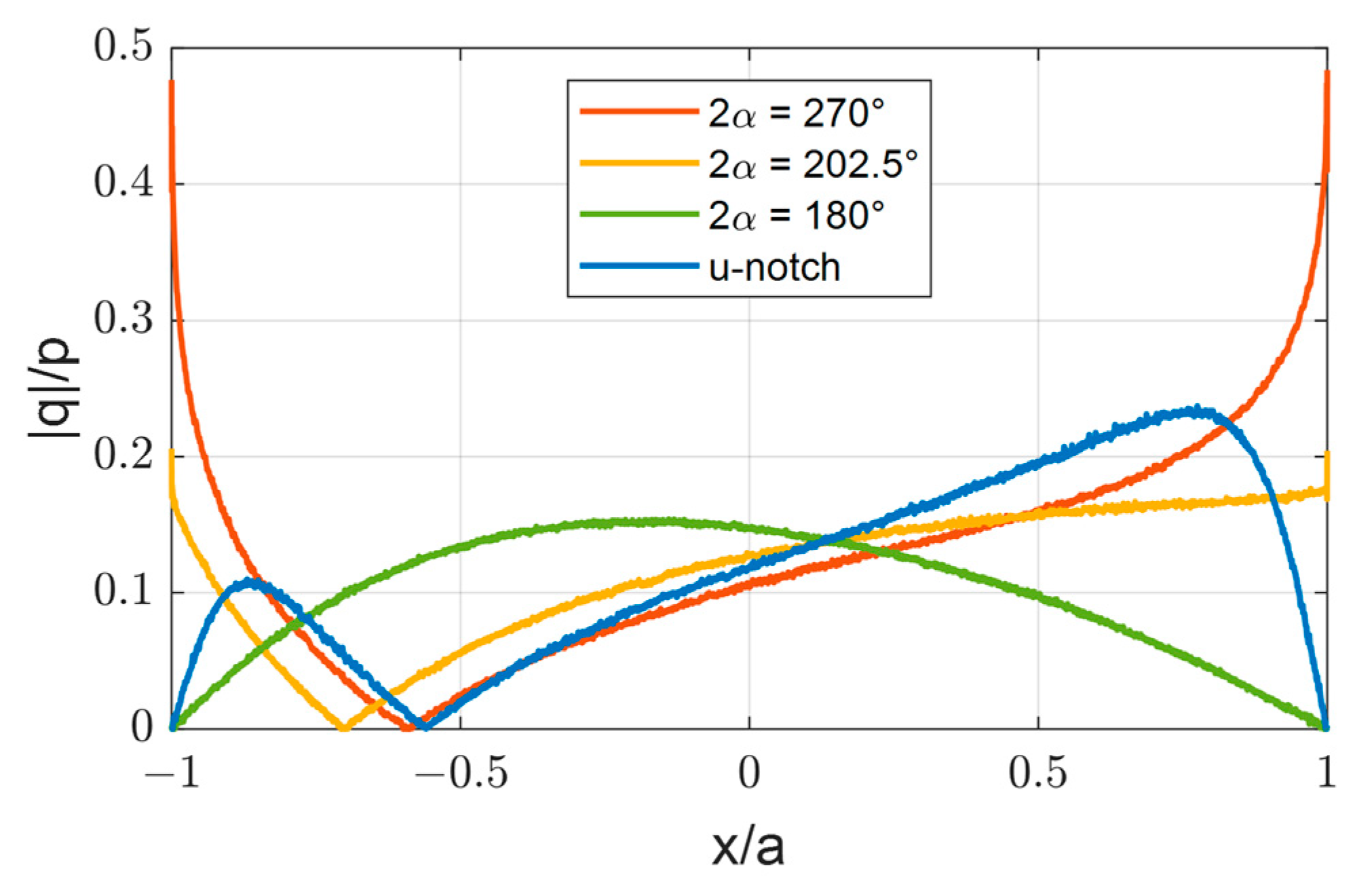
The pressure, shear traction, and traction ratio for these numerical contact models with interior edge angle 2α values of 270°, 202.5°, and 180° are computed and shown in Figure 7, Figure 8, and Figure 9, respectively, with tractions normalized with respect to normal load P and contact area A = 2ad. These represent the tractions required to maintain the bonded contact condition. A mesh sensitivity analysis was performed and showed convergence for the numerically computed traction values, except near the edges for 2α > 180°. Here, the computed traction values were found to increase with improved mesh resolution but did not converge due to the finite spatial resolution of the models and the inherent singularity near the edges, as predicted with the analytical models. However, the traction ratio values near the edges did converge to finite values in agreement with the asymptotic edge analysis. The computed traction distributions across the contact for the numerical model with 2α = 180° are also in agreement with the analysis of the analytical semi-infinite bonded strips model.
4. Contact Edge Features
To illustrate the potential and beneficial effect of novel edge features on interface tractions, a u-notch is introduced in the bottom component at both edges of the contact, as shown in Figure 6d. This feature was selected because in the limit as the notch radius decreases to zero it becomes the contact with 2α = 270°, whereas in the limit as the notch radius approaches infinity it becomes the contact with 2α = 180°. The u-notch used in the calculations presented has width and depth dimensions equal to five percent of the contact width, with bottom fillets of radius equal to two percent of the contact width.
The pressure, shear traction, and traction ratio for the contact with the edge u-notches are included in Figure 7, Figure 8 and Figure 9. These reveal the introduction of edge u-notches eliminates the singularities in the pressure and shear traction near the edges, as found in the contact with 2α = 270° and 202.5°, and results in zero shear traction and traction ratio at the edges, as found in the contact with 2α = 180°. Furthermore, these results show that not only do the u-notches reduce the shear traction at the edges from a singularity to zero, but the pressure, shear traction, and traction ratio distributions within the contact are finite.
The numerical results of the limiting cases of 2α = 270° and 180° are supported by the analytical results and bound the numerical results of the models with changes in edge geometry. This highlights the value of a combined complementing analytical and numerical modeling and analysis approach used in this work.
5. Condition for Microslip and Fretting
A condition for avoiding microslip [3] can be defined in terms of traction ratio for all points in the contact as
where μ is the coefficient of friction. Such a condition can be used to define the upper bound of acceptable traction ratio necessary to avoid microslip.
To illustrate, consider the computed traction results presented in Figure 7, Figure 8 and Figure 9 for a contact formed between two finite components. For the contact with a u-notch at the edges (i.e., the blue curve), the pressure and shear traction are finite across the entire interface, and the maximum traction ratio is 0.24. Therefore, using the condition defined by Equation (9), microslip and fretting may be avoided if the coefficient of friction for this interface is greater than 0.24.
6. Conclusions
This paper presented the concept of introducing geometrical changes and features near the edges of contacts for the purpose of reducing the inherent high localized pressure and shear traction. Two-dimensional contact models were developed. Asymptotic, closed-form, and numerical analyses of the models were presented to illustrate the effect of geometrical edge changes. A condition for avoiding microslip and fretting was presented. The results from this work reveal geometrical changes near contact edges can alter traction sufficiently to inhibit microslip and fretting wear and fatigue. The benefits of such changes in contacts include reduced complexity from nonlinearity and multiscale friction phenomena associated with microslip.
Funding
This research received no external funding.
Data Availability Statement
The data presented in this study are available on request from the corresponding author.
Conflicts of Interest
The authors declare no conflict of interest.
Nomenclature
| 2a | contact width |
| A | contact area |
| d | contact depth |
| eigenfunction for eigensolution I for stress field near edge | |
| eigenfunction for eigensolution II for stress field near edge | |
| I | second moment of cross-sectional area of infinite strip |
| KI | multiplier for eigensolution I for stress field near edge |
| KII | multiplier for eigensolution II for stress field near edge |
| M | moment |
| contact pressure, | |
| P | normal force |
| shear traction, | |
| r | variable defined from edge into wedge |
| Q | tangential force |
| y | normal coordinate at center of contact |
| 2α | internal angle of semi-infinite elastic wedge |
| θ | variable defined from the angular centerline of wedge |
| eigenvalue for eigensolution I for stress field near edge | |
| eigenvalue for eigensolution II for stress field near edge | |
| μ | coefficient of friction |
| stress field near edge | |
| shear stress in bonded infinite strip at y = 0 | |
| normal stress in bonded infinite strip at y = 0 | |
| angular position of contact interface from angular center of wedge |
References
- Timoshenko, S. History of Strength of Materials with a Brief Account of the History of Theory of Elasticity and Theory of Structures; McGraw-Hill: New York, NY, USA, 1953. [Google Scholar]
- Timoshenko, S.; Goodier, J. Theory of Elasticity, 3rd ed.; McGraw-Hill: New York, NY, USA, 1970. [Google Scholar]
- Johnson, K. Contact Mechanics; Cambridge University Press: Cambridge, UK, 1985. [Google Scholar]
- Barber, J. Contact Mechanics; Springer: Berlin/Heidelberg, Germany, 2018. [Google Scholar]
- Cattaneo, C. Sul contatto di corpi elastici. Accad. Dei Lincei Rend. 1938, 27, 342–478. [Google Scholar]
- Mindlin, R. Compliance of elastic bodies in contact. ASME J. Appl. Mech. 1949, 16, 259–268. [Google Scholar] [CrossRef]
- Johnson, K.; O’Connor, J. Mechanics of fretting. In Proceedings of the Institute of Mechanical Engineers; Sage: London, UK, 1964; Volume 178, pp. 7–21. [Google Scholar]
- Fantetti, A.; Tamatam, L.; Volvert, M.; Lawal, I.; Liu, L.; Salles, L.; Brake, M.; Schwingshackl, C.; Nowell, D. The impact of fretting wear on structural dynamics: Experiment and simulation. Tribol. Int. 2019, 138, 111–124. [Google Scholar] [CrossRef]
- Hills, D.; Andresen, H. Mechanics of Fretting and Fretting Fatigue; Springer: Berlin/Heidelberg, Germany, 2021. [Google Scholar]
- Gimpl, V.; Fantetti, A.; Klaassen, S.; Schwingshackl, C.; Rixen, D. Contact stiffness of jointed interfaces: A comparison of dynamic Substructuring techniques with frictional hysteresis measurements. Mech. Syst. Signal Process. 2022, 171, 108896. [Google Scholar] [CrossRef]
- Zhao, B.; Wu, F.; Sun, K.; Mu, X.; Zhang, Y.; Sun, Q. Study on tangential stiffness nonlinear softening of bolted joint in friction-sliding process. Tribol. Int. 2021, 156, 106856. [Google Scholar] [CrossRef]
- Li, C.; Jiang, Y.; Qiao, R.; Miao, X. Modeling and parameter identification of the connection interface of bolted joints based on an improved micro-slip model. Mech. Syst. Signal Process. 2021, 153, 107514. [Google Scholar] [CrossRef]
- Mathis, A.; Balaji, N.; Kuether, R.; Brink, A.; Brake, M.; Quinn, D. A review of damping models for structures with mechanical joints. Appl. Mech. Rev. 2020, 72, 040802. [Google Scholar] [CrossRef]
- Brake, M. The Mechanics of Jointed Structures; Springer: Berlin/Heidelberg, Germany, 2018. [Google Scholar]
- Ciavarella, M.; Hills, D.; Monno, G. The influence of rounded edges on identification by a flat punch. Proc. Inst. Mech. Eng. 1998, 212, 319–328. [Google Scholar]
Figure 1.
Two-dimensional elastic contact.

Figure 2.
Wedge model of contact edge.

Figure 3.
Changing edge angle 2α from 270° to 180°.

Figure 4.
Traction ratio at edge for range of angle 2α.

Figure 5.
Semi-infinite elastic strips contact model.

Figure 6.
Elastic contacts with (a) 2α = 270°, (b) 2α = 202.5°, (c) 2α = 180°, and (d) u-notch at edges.
Figure 6.
Elastic contacts with (a) 2α = 270°, (b) 2α = 202.5°, (c) 2α = 180°, and (d) u-notch at edges.
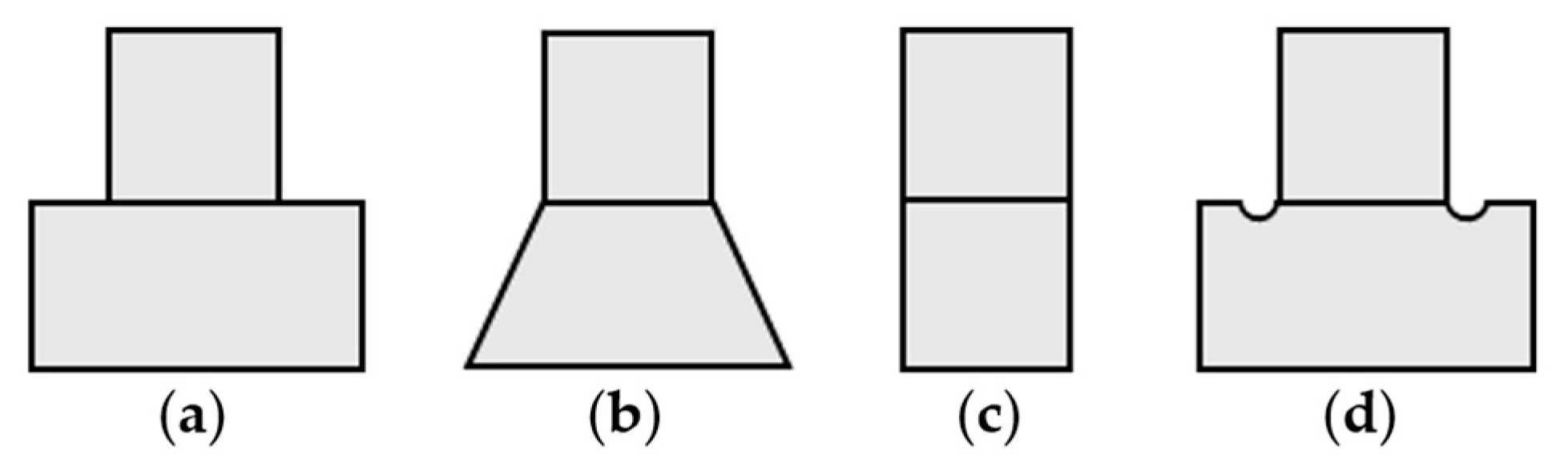
Figure 7.
Pressure for 2α = 270°, 2α = 202.5°, 2α = 180°, and u-notch at edges.

Figure 8.
Shear traction for 2α = 270°, 2α = 202.5°, 2α = 180°, and u-notch at edges.

Figure 9.
Traction ratio for 2α = 270°, 2α = 202.5°, 2α = 180°, and u-notch at edges.
Disclaimer/Publisher’s Note: The statements, opinions and data contained in all publications are solely those of the individual author(s) and contributor(s) and not of MDPI and/or the editor(s). MDPI and/or the editor(s) disclaim responsibility for any injury to people or property resulting from any ideas, methods, instructions or products referred to in the content. |
© 2023 by the author. Licensee MDPI, Basel, Switzerland. This article is an open access article distributed under the terms and conditions of the Creative Commons Attribution (CC BY) license (https://creativecommons.org/licenses/by/4.0/).
Share and Cite
MDPI and ACS Style
Hess, D. Edge Changes in Contacts and Joints to Reduce High Localized Shear Traction, Microslip, and Fretting. Lubricants 2023, 11, 488. https://doi.org/10.3390/lubricants11110488
AMA Style
Hess D. Edge Changes in Contacts and Joints to Reduce High Localized Shear Traction, Microslip, and Fretting. Lubricants. 2023; 11(11):488. https://doi.org/10.3390/lubricants11110488
Chicago/Turabian StyleHess, Daniel. 2023. "Edge Changes in Contacts and Joints to Reduce High Localized Shear Traction, Microslip, and Fretting" Lubricants 11, no. 11: 488. https://doi.org/10.3390/lubricants11110488
Note that from the first issue of 2016, this journal uses article numbers instead of page numbers. See further details here.