Microstructure and Wear Resistance of Fe3Al Coating on Grey Cast Iron Prepared via Direct Energy Deposition

 , ,
, ,  , and
, and
Abstract
:1. Introduction
2. Materials and Methods
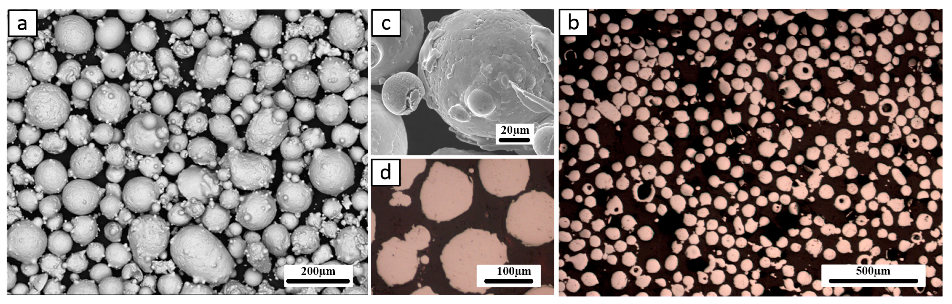
2.1. Materials
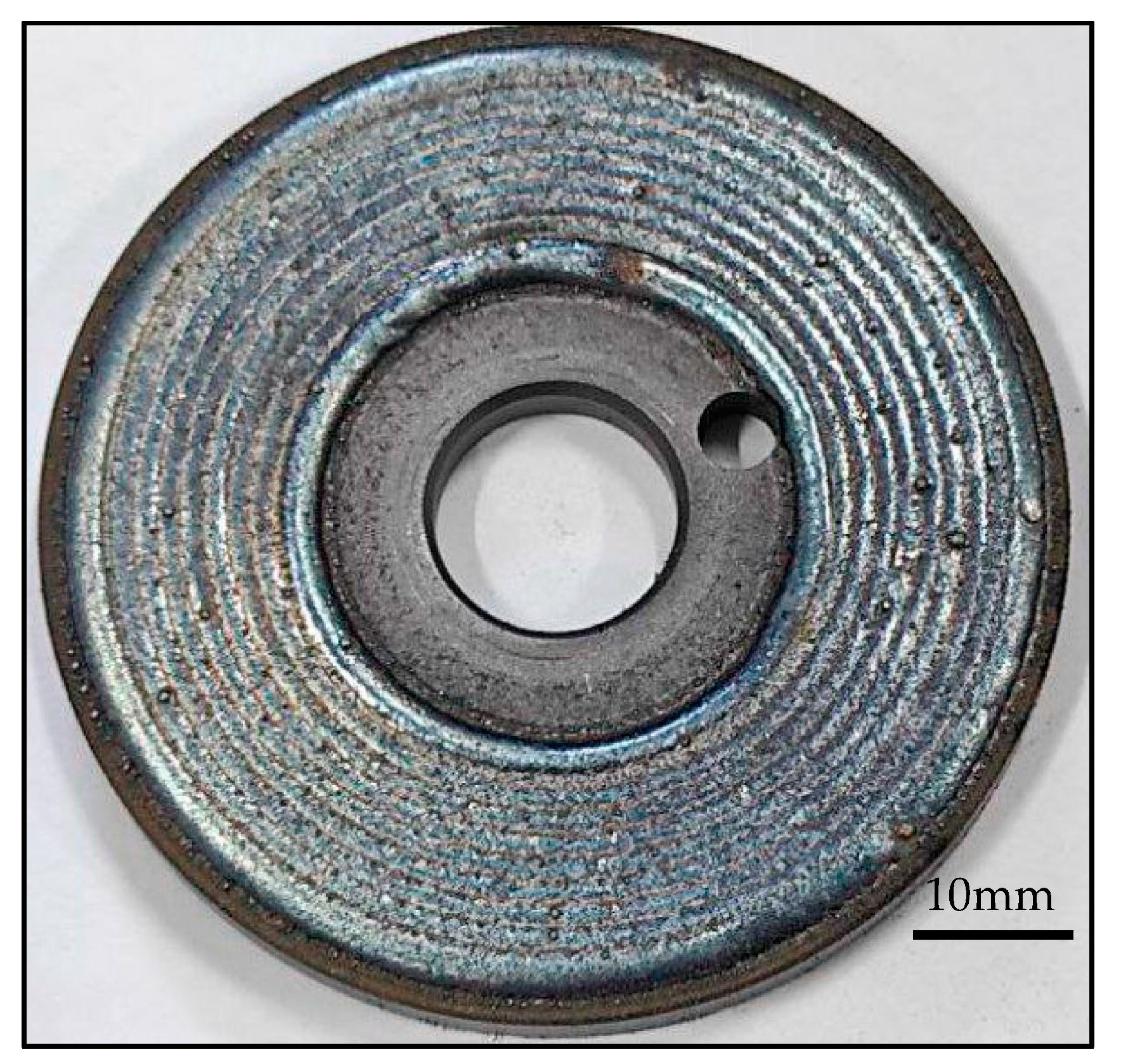
2.2. Coating Deposition
2.3. Wear Test
2.4. Wear and Emission Measurements
2.5. Characterization
3. Results and Discussion
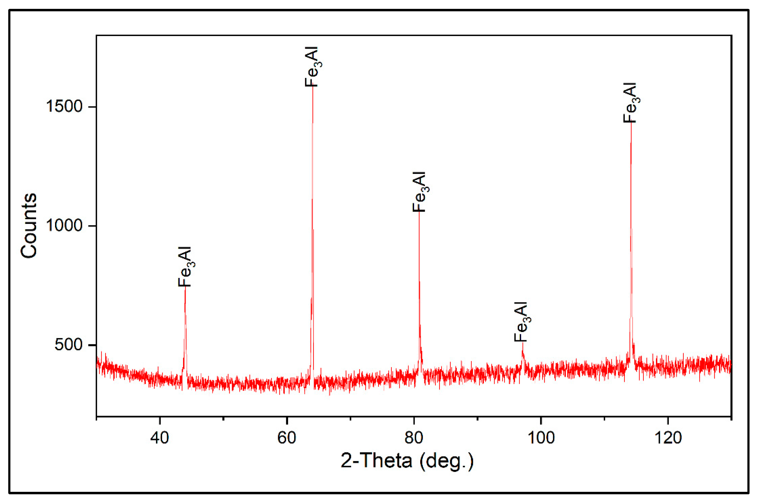
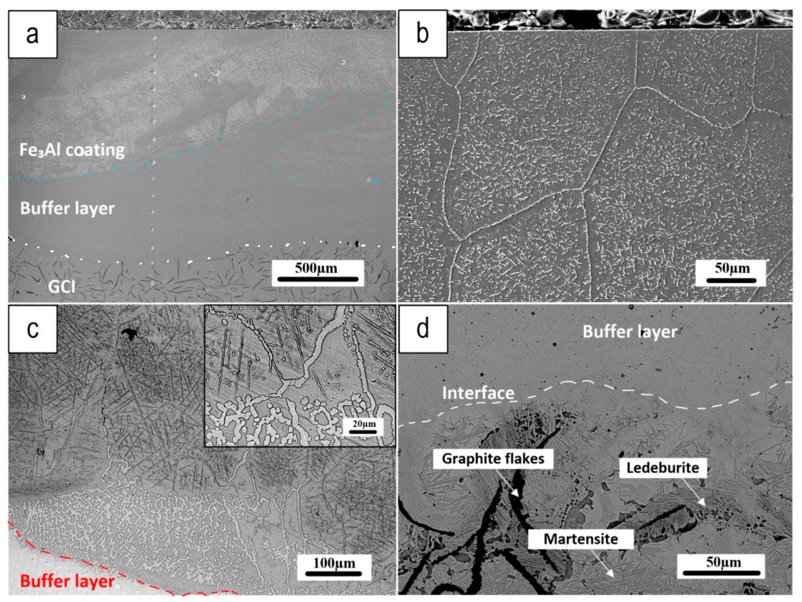
3.1. Coating Characterization
3.2. Wear Test Results
4. Conclusions
Author Contributions
Funding
Data Availability Statement
Conflicts of Interest
References
- Lyu, Y.; Leonardi, M.; Mancini, A.; Wahlström, J.; Olofsson, U. Tribology and Airborne Particle Emission of Laser-Cladded Fe-Based Coatings versus Non-Asbestos Organic and Low-Metallic Brake Materials. Metals 2021, 11, 1703. [Google Scholar] [CrossRef]
- Aranke, O.; Algenaid, W.; Awe, S.; Joshi, S. Coatings for Automotive Gray Cast Iron Brake Discs: A Review. Coatings 2019, 9, 552. [Google Scholar] [CrossRef]
- Verma, P.C.; Alemani, M.; Gialanella, S.; Lutterotti, L.; Olofsson, U.; Straffelini, G. Wear debris from brake system materials: A multi-analytical characterization approach. Tribol. Int. 2016, 94, 249–259. [Google Scholar] [CrossRef]
- Zhang, Q.; Lu, D.; Wang, D.; Yang, X.; Zuo, P.; Yang, H.; Fu, Q.; Liu, Q.; Jiang, G. Separation and Tracing of Anthropogenic Magnetite Nanoparticles in the Urban Atmosphere. Environ. Sci. Technol. 2020, 54, 9274–9284. [Google Scholar] [CrossRef]
- Ciudin, R.; Verma, P.C.; Gialanella, S.; Straffelini, G. Wear debris materials from brake systems: Environmental and health issues. WIT Trans. Ecol. Environ. 2014, 191, 1423–1434. [Google Scholar] [CrossRef]
- Li, W.; Yang, X.; Wang, S.; Xiao, J.; Hou, Q. Comprehensive Analysis on the Performance and Material of Automobile Brake Discs. Metals 2020, 10, 377. [Google Scholar] [CrossRef]
- Opel, T.; Langhof, N.; Krenkel, W.; Krenkel, I.W. Development and tribological studies of a novel metal-ceramic hybrid brake disc. Int. J. Appl. Ceram. Technol. 2022, 19, 62–74. [Google Scholar] [CrossRef]
- Goo, B.-C. Development and Characterization of C/C-SiC Brake Disc. Mater. Manuf. Process. 2016, 31, 979–988. [Google Scholar] [CrossRef]
- Rajaei, H.; Menapace, C.; Amirabdollahian, S.; Perini, M.; Straffelini, G.; Gialanella, S. Microstructural and Tribological Evaluation of Brake Disc Refurbishing Using Fe-Based Coating via Directed Energy Deposition. Metals 2022, 12, 465. [Google Scholar] [CrossRef]
- Shamanian, M.; Abarghouie, S.M.; Pour, S.M. Effects of surface alloying on microstructure and wear behavior of ductile iron. Mater. Des. 2010, 31, 2760–2766. [Google Scholar] [CrossRef]
- Chioibasu, D.; Mihai, S.; Cotrut, C.M.; Voiculescu, I.; Popescu, A.C. Tribology and corrosion behavior of gray cast iron brake discs coated with Inconel 718 by direct energy deposition. Int. J. Adv. Manuf. Technol. 2022, 121, 5091–5107. [Google Scholar] [CrossRef]
- Kılıç, H.; Mısırlı, C.; Mutlu, I.; Timur, M. Mechanical and tribological properties of a WC-based HVOF spray coated brake disc. Mater. Test. 2022, 64, 1150–1161. [Google Scholar] [CrossRef]
- Olofsson, U.; Lyu, Y.; Åström, A.H.; Wahlström, J.; Dizdar, S.; Nogueira, A.P.G.; Gialanella, S. Laser Cladding Treatment for Refurbishing Disc Brake Rotors: Environmental and Tribological Analysis. Tribol. Lett. 2021, 69, 57. [Google Scholar] [CrossRef]
- Rettig, M.; Grochowicz, J.; Käsgen, K.; Eaton, R.; Wank, A.; Hitzek, A.; Schmengler, C.; Koss, S.; Voshage, M.; Verpoort, C.; et al. Carbidic Brake Rotor Surface Coating Applied by High-performance-laser Cladding. In Proceedings of the Euro Brake 2020, Online, 16–19 June 2020. [Google Scholar] [CrossRef]
- Dizdar, S.; Lyu, Y.; Lampa, C.; Olofsson, U. Grey Cast Iron Brake Discs Laser Cladded with Nickel-Tungsten Carbide—Friction, Wear and Airborne Wear Particle Emission. Atmosphere 2020, 11, 621. [Google Scholar] [CrossRef]
- Bastian, S.; Busch, W.; Kühnel, D.; Springer, A.; Meißner, T.; Holke, R.; Scholz, S.; Iwe, M.; Pompe, W.; Gelinsky, M.; et al. Toxicity of Tungsten Carbide and Cobalt-Doped Tungsten Carbide Nanoparticles in Mammalian Cells in Vitro. Environ. Heal. Perspect. 2009, 117, 530–536. [Google Scholar] [CrossRef]
- US National Toxicology Program (NTP). Available online: https://ntp.niehs.nih.gov/ (accessed on 17 May 2023).
- European Chemical Agency. Available online: https://echa.europa.eu/home (accessed on 17 May 2023).
- Liu, Z.; Han, Q.; Guo, Y.; Lang, J.; Shi, D.; Zhang, Y.; Huang, Q.; Deng, H.; Gao, F.; Sun, B.; et al. Development of interatomic potentials for Fe-Cr-Al alloy with the particle swarm optimization method. J. Alloy. Compd. 2019, 780, 881–887. [Google Scholar] [CrossRef]
- Mulyawan, A.; Terai, T.; Fukuda, T. Interpretation of Fe-rich part of Fe–Al phase diagram from magnetic properties of A2-, B2-, and DO3-phases. J. Alloy. Compd. 2020, 834, 155140. [Google Scholar] [CrossRef]
- Luo, X.; Zhang, K.; Cao, J.; Meng, G.; Yu, F.; Zhou, Y.; Zhou, H.; La, P.; Xie, H. Effect of line energy density of the laser beam on the microstructure and wear resistance properties of the obtained Fe3Al laser cladding coatings. Optik 2022, 261, 169256. [Google Scholar] [CrossRef]
- Alman, D.E.; Hawk, J.A.; Tylczak, J.H.; Doğan, C.P.; Wilson, R.D. Wear of iron-aluminide intermetallic-based alloys and composites by hard particles. Wear 2001, 251, 875–884. [Google Scholar] [CrossRef]
- Menapace, C.; Leonardi, M.; Matějka, V.; Gialanella, S.; Straffelini, G. Dry sliding behavior and friction layer formation in copper-free barite containing friction materials. Wear 2018, 398–399, 191–200. [Google Scholar] [CrossRef]
- Grum, J.; Šturm, R. Comparison of measured and calculated thickness of martensite and ledeburite shells around graphite nodules in the hardened layer of nodular iron after laser surface remelting. Appl. Surf. Sci. 2002, 187, 116–123. [Google Scholar] [CrossRef]
- McKamey, C.; Liu, C. Chromium addition and environmental embrittlement in Fe3Al. Scr. Met. Et Mater. 1990, 24, 2119–2122. [Google Scholar] [CrossRef]
- Deevi, S.C. Advanced intermetallic iron aluminide coatings for high temperature applications. Prog. Mater. Sci. 2021, 118, 100769. [Google Scholar] [CrossRef]
- Johansson, P.; Uhrenius, B.; Wilson, A.; Ståhlberg, U. Processing, Fabrication, and Mechanical Properties of Fe3Al Based PM Alloys. Powder Met. 1996, 39, 53–58. [Google Scholar] [CrossRef]
- Parvathavarthini, N.; Prakash, U.; Dayal, R. Effect of carbon addition on hydrogen permeation in an Fe3Al-based intermetallic alloy. Intermetallics 2002, 10, 329–332. [Google Scholar] [CrossRef]
- Sundar, R.S.; Deevi, S.C. Effect of carbon addition on the strength and creep resistance of FeAl alloys. Metall Mater Trans A Phys Metall Mater Sci 2003, 34, 2233–2246. [Google Scholar] [CrossRef]
- Zhu, S.M.; Guan, X.S.; Shibata, K.; Iwasaki, K. Effect of carbon addition on tribological properties of Fe-Al alloys. Metall. Mater. Trans. A Phys. Metall. Mater. Sci. 2002, 33, 1292–1295. [Google Scholar] [CrossRef]
- Cho, M.H.; Cho, K.H.; Kim, S.J.; Kim, D.H.; Jang, H. The Role of Transfer Layers on Friction Characteristics in the Sliding Interface between Friction Materials against Gray Iron Brake Disks. Tribol. Lett. 2005, 20, 101–108. [Google Scholar] [CrossRef]
- Franck, U.; Odeh, S.; Wiedensohler, A.; Wehner, B.; Herbarth, O. The effect of particle size on cardiovascular disorders—The smaller the worse. Sci. Total. Environ. 2011, 409, 4217–4221. [Google Scholar] [CrossRef]


| Fe | Cr | Mo | Mn | Si | C | |
|---|---|---|---|---|---|---|
| Ferro 55 | Bal. | 7 | 2.2 | 1.1 | 0.3 | 0.35 |
| Elements (wt%) | Cu-Free | ECOPADS |
|---|---|---|
| O | 26 ± 1 | 26 ± 1 |
| Mg | 8 ± 1 | 2.2 ± 0.5 |
| Al | 6.1 ± 0.2 | 1.6 ± 0.5 |
| S | 4 ± 1 | 7 ± 1 |
| Si | 3.4 ± 0.6 | 0.3 ± 0.6 |
| Ca | 5.1 ± 0.8 | 3.2 ± 0.3 |
| Zn | 12 ± 1 | 13.7 ± 0.8 |
| Cr | 2.5 ± 0.2 | 2 ± 0.4 |
| Fe | 28 ± 2 | 21 ± 4 |
| Sn | 8.1 ± 0.5 | 5.2 ± 0.5 |
| Ba | - | 21 ± 3 |
| B1 (wt.%) | B2 (wt.%) | B3 (wt.%) | |
|---|---|---|---|
| O | 3 | 19.3 | 20.8 |
| Al | 11.9 | 7.9 | 8.8 |
| Cr | 1.0 | 1.1 | 0.8 |
| Fe | 83.3 | 57.2 | 55.9 |
| Mg | 0.4 | 3.9 | 2.8 |
| Si | 0.4 | 1.5 | 1.8 |
| Zn | - | 3.9 | 3.8 |
| Sn | - | 2.3 | 2.4 |
| S | - | 2.2 | 2.3 |
| Ca | - | 0.7 | 0.6 |
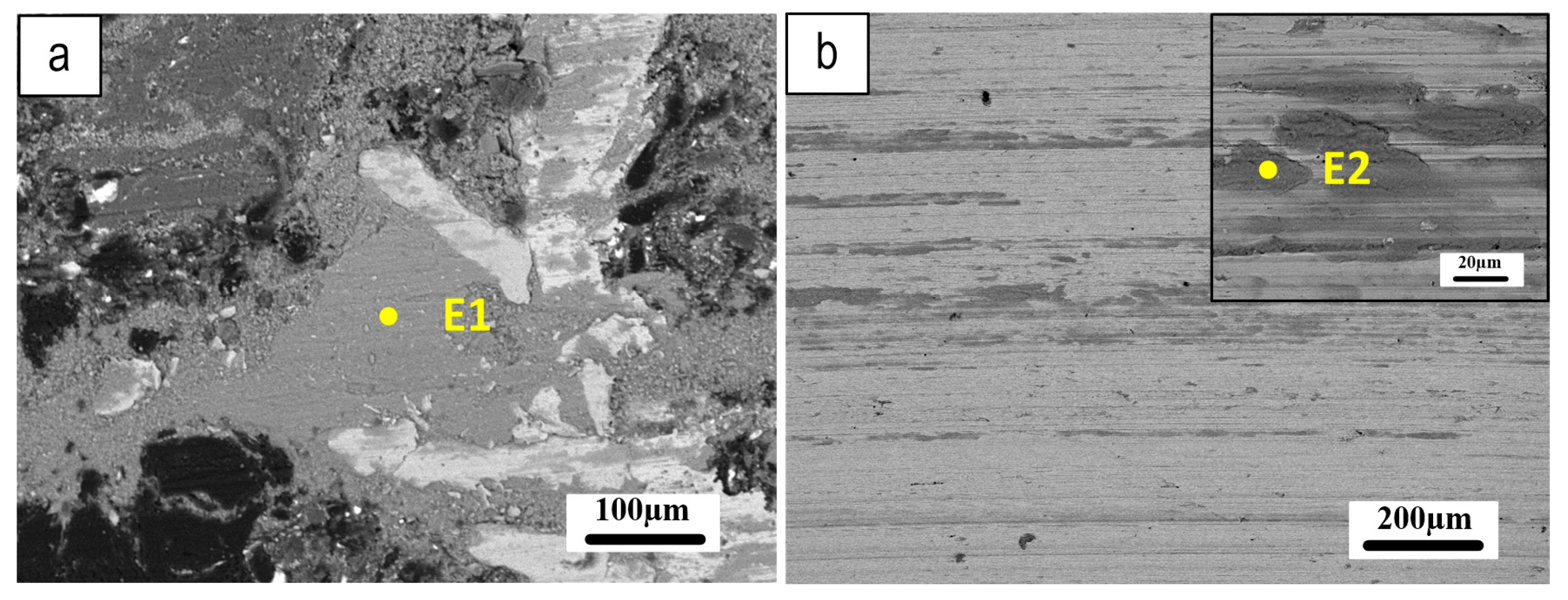
| E1 (wt.%) | E2 (wt.%) | |
|---|---|---|
| O | 22.6 | 18.7 |
| Al | 7.4 | 8.5 |
| Cr | 0.8 | 0.7 |
| Fe | 52.1 | 51.2 |
| Ba | 6.4 | 7.0 |
| Mg | 2.3 | 2.7 |
| Si | 1 | 1.0 |
| Zn | 2.2 | 3.2 |
| Sn | 1.5 | 2.1 |
| S | 3.1 | 3.7 |
| Ca | 0.6 | 0.8 |
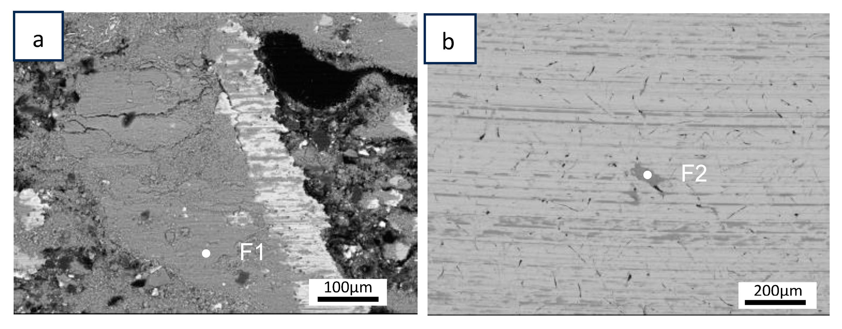
| F1 (wt.%) | F2 (wt.%) | |
|---|---|---|
| O | 28 | 26.8 |
| Al | 1.4 | 1.3 |
| Cr | 0.4 | 0.6 |
| Fe | 61 | 62.3 |
| Mg | 1.7 | 1.8 |
| Si | 1.4 | 1.4 |
| Zn | 2.5 | 2 |
| Sn | 1.4 | 1.6 |
| S | 1.3 | 1.3 |
| Ca | 0.4 | 0.4 |
| Mn | 0.5 | 0.5 |
Disclaimer/Publisher’s Note: The statements, opinions and data contained in all publications are solely those of the individual author(s) and contributor(s) and not of MDPI and/or the editor(s). MDPI and/or the editor(s) disclaim responsibility for any injury to people or property resulting from any ideas, methods, instructions or products referred to in the content. |
© 2023 by the authors. Licensee MDPI, Basel, Switzerland. This article is an open access article distributed under the terms and conditions of the Creative Commons Attribution (CC BY) license (https://creativecommons.org/licenses/by/4.0/).
Share and Cite
Rajaei, H.; Amirabdollahian, S.; Menapace, C.; Straffelini, G.; Gialanella, S. Microstructure and Wear Resistance of Fe3Al Coating on Grey Cast Iron Prepared via Direct Energy Deposition. Lubricants 2023, 11, 477. https://doi.org/10.3390/lubricants11110477
Rajaei H, Amirabdollahian S, Menapace C, Straffelini G, Gialanella S. Microstructure and Wear Resistance of Fe3Al Coating on Grey Cast Iron Prepared via Direct Energy Deposition. Lubricants. 2023; 11(11):477. https://doi.org/10.3390/lubricants11110477
Chicago/Turabian StyleRajaei, Hossein, Sasan Amirabdollahian, Cinzia Menapace, Giovanni Straffelini, and Stefano Gialanella. 2023. "Microstructure and Wear Resistance of Fe3Al Coating on Grey Cast Iron Prepared via Direct Energy Deposition" Lubricants 11, no. 11: 477. https://doi.org/10.3390/lubricants11110477
APA StyleRajaei, H., Amirabdollahian, S., Menapace, C., Straffelini, G., & Gialanella, S. (2023). Microstructure and Wear Resistance of Fe3Al Coating on Grey Cast Iron Prepared via Direct Energy Deposition. Lubricants, 11(11), 477. https://doi.org/10.3390/lubricants11110477