Article

Mass and Energy Balance of a Three-Body Tribosystem

Laboratoire Génie de Production (LGP), Université de Toulouse, INP-ENIT, 47 Avenue d’Azereix, 65000 Tarbes, France
Lubricants 2022, 10(5), 95; https://doi.org/10.3390/lubricants10050095
Submission received: 27 March 2022 / Revised: 2 May 2022 / Accepted: 9 May 2022 / Published: 12 May 2022

Abstract

:
In the context of sustainable development and under the impulse of continuous technological progress, tribology contributes to the improvement of the life span of parts in dynamic contact and to the efficiency of mechanical systems. However, even if successes are obtained in lubrication, the tribology community struggles to build generalised laws of friction and wear in the case of dry friction. Based on the thermodynamics of open systems, we suggest an adaptation of the conservation of mass and energy equations to the tribosystem. The latter is modelled using the concepts of tribological triplet, tribological circuit and accommodation mechanisms. The tribosystem is described with four control volumes: two of them represent the first two bodies in dynamic contact; a third one is the tribofilm produced by the debris emission from the first bodies; a fourth control volume is used as an interface between the third body and the external environment. A mass balance is applied to these four control volumes by considering their interactions. An energy balance is then derived by applying the first principle of thermodynamics. Two systems of interdependent equations that describe the circulation of matter and energy flows in the tribosystem are outlined. These equations can be considered as a basis for future experimental developments that would aim at simultaneously characterising the different modes of energy dissipation in dynamic contact, qualitatively and especially quantitatively.

1. Introduction

Tribology focuses on understanding matter and energy consumption in a mechanical system when motion acts between two parts in contact. It is a societal issue since we are looking for solutions to limit our energy consumption and produce fewer greenhouse gases in the context of climate change. Tribology contributes to limiting the excessive consumption of raw materials and energy. Tribologists have been interested in the mechanism inherent in friction and wear phenomena for centuries [1]. In the field of lubrication, it is possible to use fluid mechanics and the Navier–Stokes equations to describe the lubricant flow between the two parts (first bodies) in contact [2,3]. Relationships expressing the conservation of matter and energy can then be deduced. This provides robust results in experimental and numerical modelling [4,5,6,7].
In this study, we are interested in dry friction, i.e., the absence of liquid lubricants or greases. Examples are brakes, bearings, gears, wheels and clutches where liquid lubricants and greases are not allowed. These may be applications in the medical industry [8,9,10,11,12], in space applications [13,14] or at high temperatures [15,16,17,18,19,20].
In the case of dry friction, there is no general law comparable to fluid mechanics to depict friction and wear, which is a gap in our knowledge. The scientific approaches often appear as phenomenological studies and stand supported by experimentation. The three-body approach can be considered as a fundamental representation of tribological phenomena in dry friction. This representation depicts an extension of the two-body model of Boden and Tabor. Indeed, in the 1950s, these two authors proposed a description of metal friction at the scale of asperities in three stages [21]:
  • the contact formation;
  • the formation of a junction;
  • the contact separation.
Boden and Tabor’s approach makes it possible to describe damage scenarios through two mechanisms: ploughing and adhesion. Later, lubrication inspired Godet [22] to explain the formation of debris and make them intervene in the dynamics of contact. He introduced the idea of a third body built by the succession of the following stages:
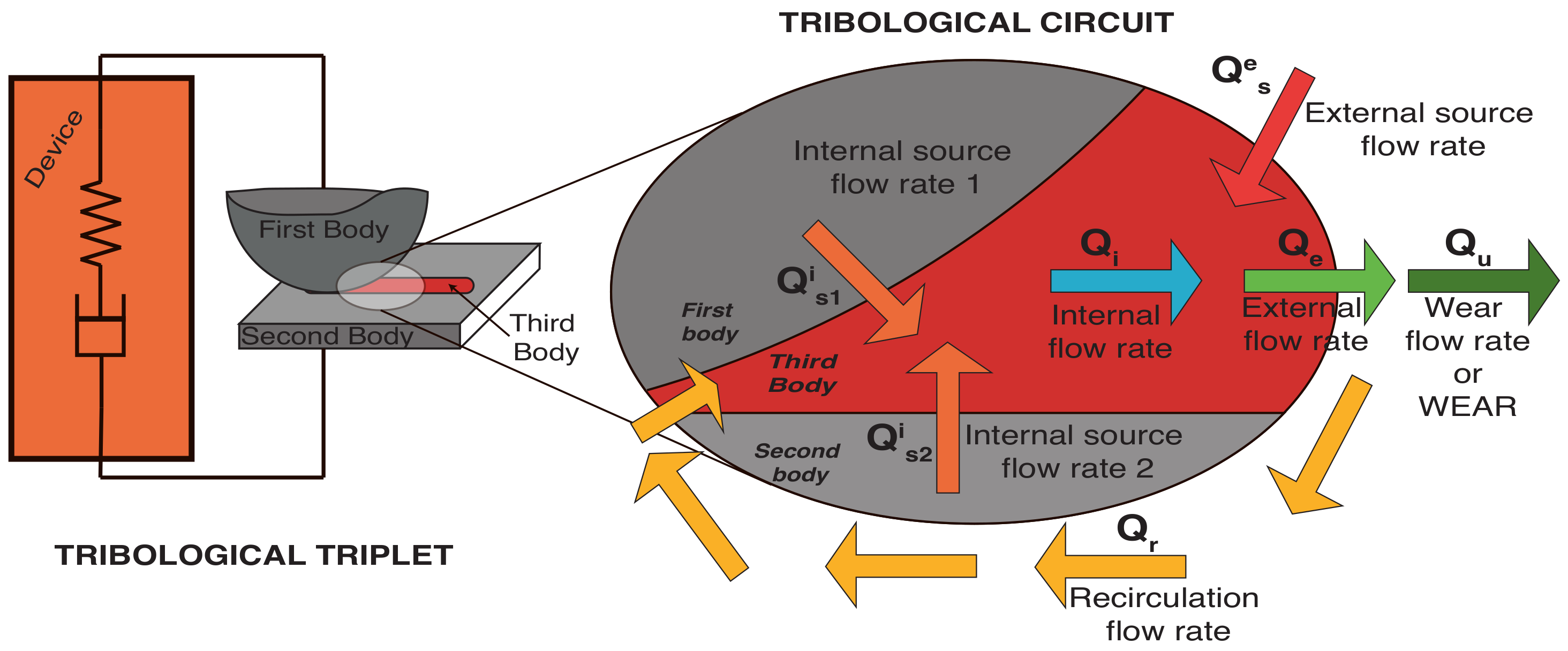
  • the production of debris by the first bodies;
  • the circulation of the debris in the interface;
  • the ejection of the debris from the contact.
In Godet’s scenario, the first bodies emit debris in the interface. Furthermore, the contact dynamic generates the third body. It reduces the interactions between the two first bodies by separating them partially or totally. This third body appears as a new material whose composition reflects the mixture of the first and second bodies. Its structure, and thus its properties, can evolve with the contact conditions.
Besides this proposal, Godet integrates the mechanical device, the two first bodies and the third bodies, in a unique representation. He calls this the tribological triplet (Figure 1). We will sometimes name it the tribosystem. The system is then characterised at all scales, from macroscopic (mechanical device) to nanometres (third body). This systemic approach considers all parts involved in the dynamic contact and their interactions. A tribological property is not attributed to a material, such as Young’s modulus or the thermal conductivity. Tribological phenomena are not considered intrinsic properties but as utilisation properties.
Later, Yves Berthier sets a typology of accommodation mechanisms that intervene in the different sites where energy can be dissipated [23,24]. Thus, he lists five sites and four modes of accommodation (Figure 2 and Table 1): elastic deformation, rupture, shear and rolling.
Afterwards, Jean Denape reinforces this approach by adding a plastic deformation mode of accommodation and modifying Berthier’s notation order [25,26]. By the way, the notation in this article adopts Denape’s description (Figure 2 and Table 2).
In his turn, Berthier reinforces Godet’s description of the third body formation by describing the flow rates of matter in the tribosystem (Figure 1). He distinguishes between internal and external source flow rates, noted respectively Q s i and Q s e : the former are debris coming from the first bodies, Q s 1 i and Q s 2 i ; the latter represent matter arriving from outside the contact, such as a lubricant, for example. The internal flow rate Q i designates the matter flowing in the contact area. Material flowing out of the contact is associated with an external flow rate Q e . A subdivision of the external flow rate is suggested. The amount of matter definitively lost from the interface is named wear and noted Q w . The matter that may come back inside the contact is noted Q r and called the recirculation flow rate. Again, it may be due to the kinematics of the movement or the design of the mechanical device. Thus, Berthier links these flow rates by continuity relations:
Q s = Q s 1 i + Q s 2 i + Q s e
Q e = Q w + Q r
Q i = Q s Q w .
This balance expresses the conservation of mass in the tribosystem. Fillot and his collaborators have experimentally validated it [27,28,29]. An energy balance describing the first principle of thermodynamics would be a natural extension of these mass conservation equations.
In 2000, M. Dragon-Louiset was interested in sliding two bodies with granular debris. A viscous fluid models this debris. With this model, she devises an energetic approach of wear [30,31].
Horst Czichos proposed in 2009 a systemic approach in tribology with an energy balance from thermodynamic considerations [32].
In 2011, Lyashenko et al. proposed a thermodynamic approach to dynamic contact by considering an ultra-thin lubricating fluid at the interface. These authors relate the frictional force, the temperature of the lubricant, the shear rate between the surfaces and the pressure [33].
Maria Marciąg’s work, in 2010 and 2015, focused on writing a mass and energy balance of a tribological system. However, this work, while tempting to propose a predictive law for wear, does not take into account the external flow of debris as mentioned by Berthier [34,35].
In 2014, Banjac et al. described a model of tribological contact while considering an open system to describe the first bodies. However, the authors do not consider the third body in their approach. Instead, they consider an exchange of matter between the two bodies as in the Bowden and Tabor model. In addition, it should be noted that these authors introduce an element that has not been addressed by previous works: the non-thermal energy, or work, associated with deformation [36].
S. V. Federov sets out a model for sliding friction energy in his articles of 2015 and 2021 [37,38,39]. He considers the transformation and dissipation of energy and proposes equations for the energy balance of friction and an energy interpretation of the friction coefficient.
The authors are often convinced that a thermodynamic approach would significantly contribute to tribological studies. Still, they note that it is not necessarily widespread in contemporary literature and work. However, these contributions, taken one by one, propose relevant energy approaches but do not concomitantly provide a mass balance and an energy balance built around a triplet, a tribological circuit, and accommodation mechanisms in the framework of open systems. From these considerations, two gaps appear in the field of dry friction:
  • There is no expression of the mass balance determined from a thermodynamic approach of open systems;
  • No energy balance follows from this.
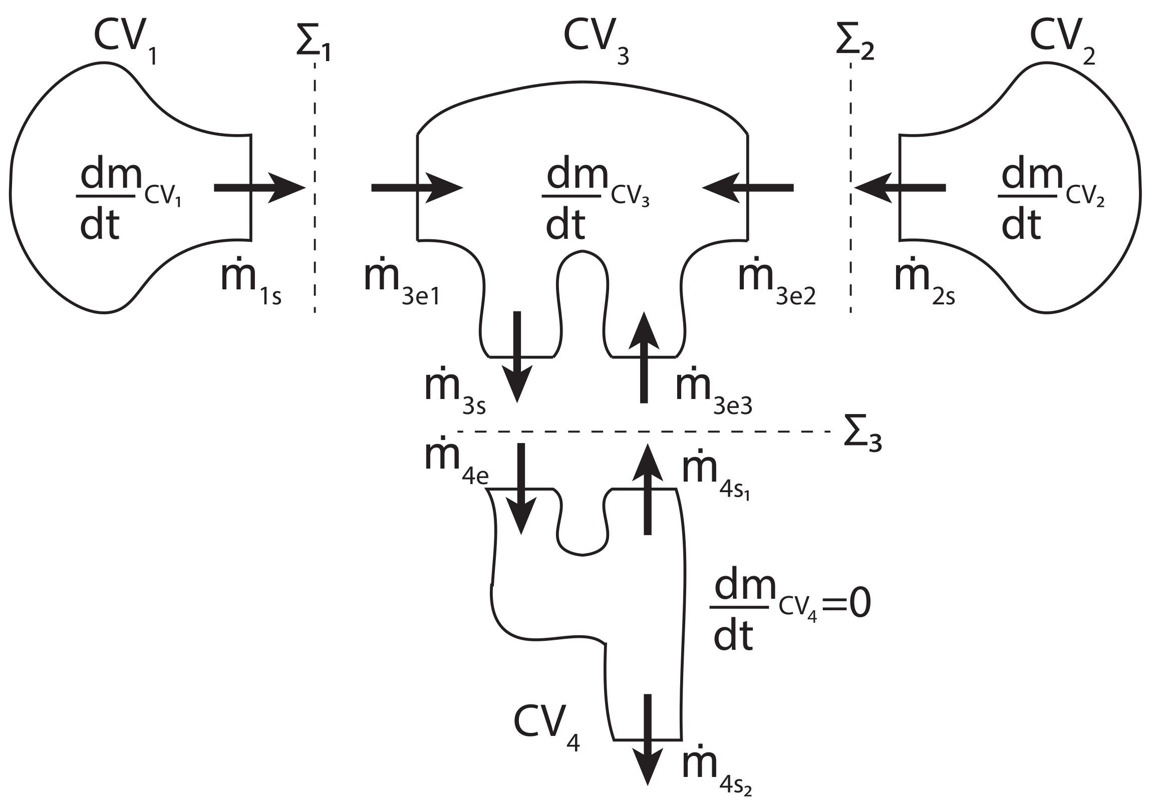
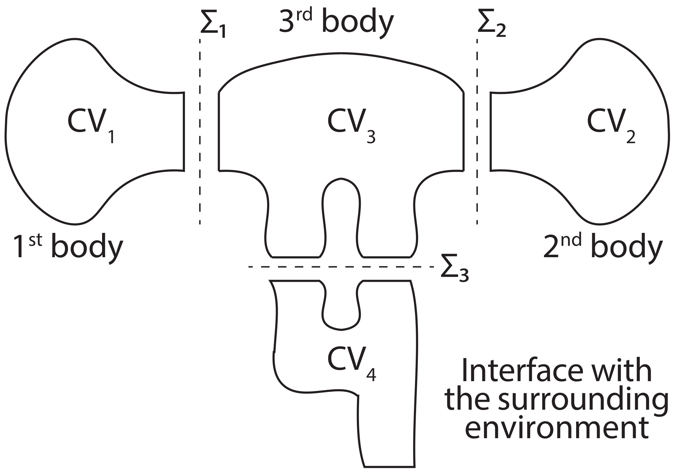
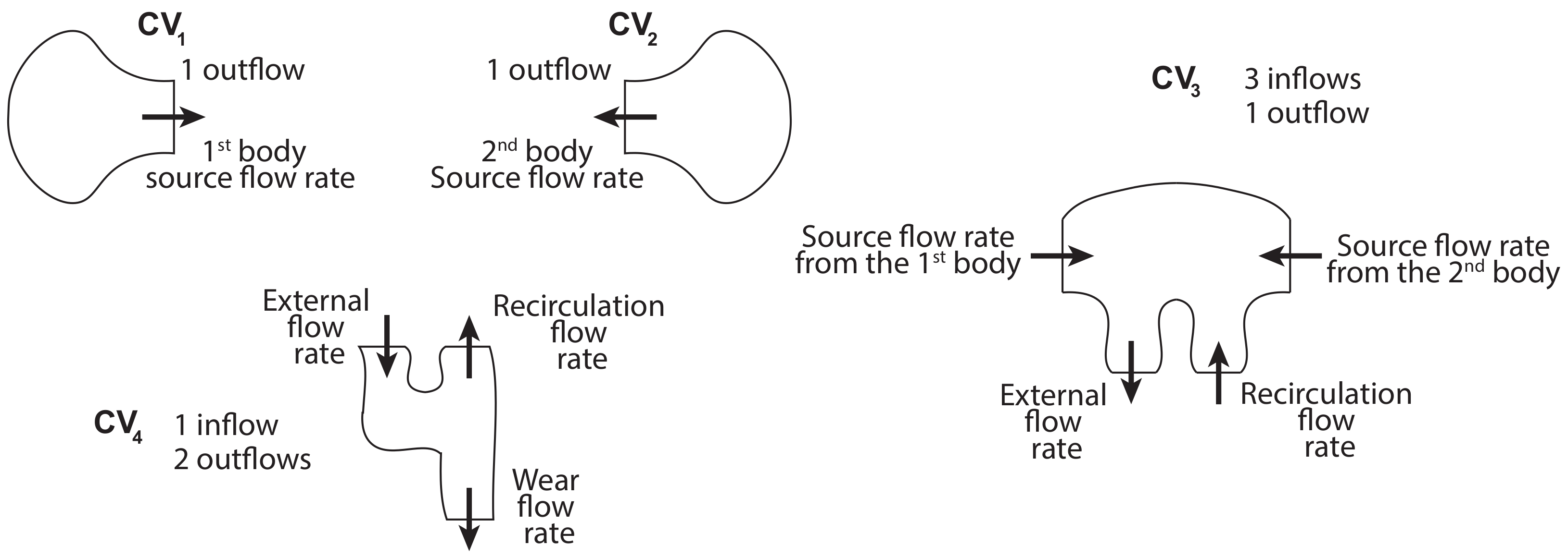
In this study, a proposition to model the tribosystem by interdependent control volumes and expressing the mass balances of these control volumes is performed (Section 2). Then, from the mass balances, the first principle of thermodynamics is applied and thus allows expressing the energy balance of each control volume (Section 3).

2. Mass Balance

The tribological system is defined as a set of open control volumes [40]. We consider the two first bodies, the third body and a fourth control volume that interfaces the third body and the environment (Figure 3).
Each system is represented in a control volume (CV) which is noted as follows:
  • CV1, the first body;
  • CV2, the second body;
  • CV3, the third body;
  • CV4, the fourth body, or the interface with the environment which models the external flow rate.
The control volumes are separated in pairs by control surfaces:
  • Σ 1 , between the first body and the third body;
  • Σ 2 , the second body and the third body;
  • Σ 3 , the third body and the wear;
In the rest of this paper, the following assumptions are made: This model does not consider the experimental device S0 and the screens, S4 and S5. There is no chemical reaction, and the two first bodies cannot gain mass. The boundary that separates the first body and the external medium does not allow the exchange of thermal energy. This simplifying assumption is retained for the boundary between the second body and the external environment and the control surface between the fourth control volume and the external environment. However, the first, second, and fourth control volumes can exchange matter and energy with the third body through their openings. The fourth control volume, which interfaces the third body with the external environment, can discharge some of its contents (mass and energy) to the external environment. As the fourth control volume is an interface, we consider that its mass and energy do not vary.
Each control volume has inflows and outflows listed as follows:
  • CV1, one outflow, noted s;
  • CV2, one outflow, noted s;
  • CV3, three inflows and one outflow, noted e 1 , e 2 , e 3 and s respectively;
  • CV4, one inflow and two outflow, noted e, s 1 and s 2 .
Figure 4 schematises the inflows and outflows of each control volume. There is no entry into the first bodies. Therefore, the matter will not circulate from the third body to the two first bodies.
In the case of the third body, the inflows allow the reception of the matter coming from the first bodies and to model the source flows Q s 1 i and Q s 2 i described in Y. Berthier’s tribological circuit. Thus, the inflow e 1 links the first and third bodies. The inflow e 2 connects the second body and the third body. The outflow s of the third body is identifiable with the external flow Qe and represents the material escaping from the third body to the outside of the contact, CV4. Finally, the third inflow e 3 accounts for the recirculation flow rate, Qr, i.e., the matter that returns in the third body after exiting it through s.
The CV4 materialises the interface with the surrounding environment and allows for a description of the external flow. It has an inlet e through which the material of the third body enters. The first outlet s 1 returns the material to the third body. The second outlet, s 1 , finally discharges the material to the outside environment, Q w . Generally, the variation of mass of the control volume is equivalent to the difference between the mass that enters it and that which leaves it.
Δ m C V = e Δ m e s Δ m s .
If we reduce this variation to the duration of the experiment Δ t , this leads to:
Δ m C V Δ t = e Δ m e Δ t s Δ m s Δ t .
Considering a short test duration, it is possible to obtain the variation of the mass in the control volume as a function of the material flow:
d m C V d t = e m ˙ e s m ˙ s .
Figure 5 represents the inflow and outflow flows of each control volume, with:
  • m ˙ 1 s , the mass flow rate leaving the first body, it is the first source flow rate;
  • m ˙ 2 s , the mass flow rate leaving the second body, it is the second source flow rate;
  • m ˙ 3 e 1 , the first flow entering the third body and coming from the first body;
  • m ˙ 3 e 2 , the second flow entering the third body from the second body;
  • m ˙ 3 e 3 , this third mass flow enters the third body. The matter arrives from the fourth control volume. This is the recirculation flow;
  • m ˙ 3 s , the mass flow out of the third body into the fourth body is the external flow;
  • m ˙ 4 e , the mass flow entering the fourth body and coming from the third body;
  • m ˙ 4 s 1 , the mass flow rate leaving the fourth body and recirculating to the third body;
  • m ˙ 4 s 2 , the mass flow leaving the fourth control volume and which is evacuated definitively to the outside. This is the wear.
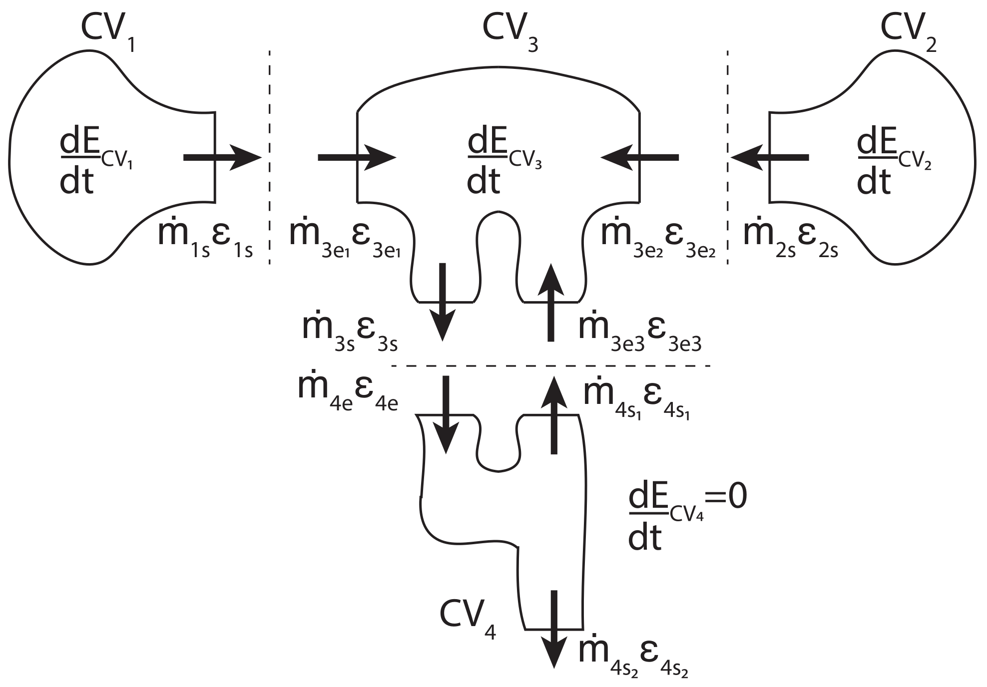
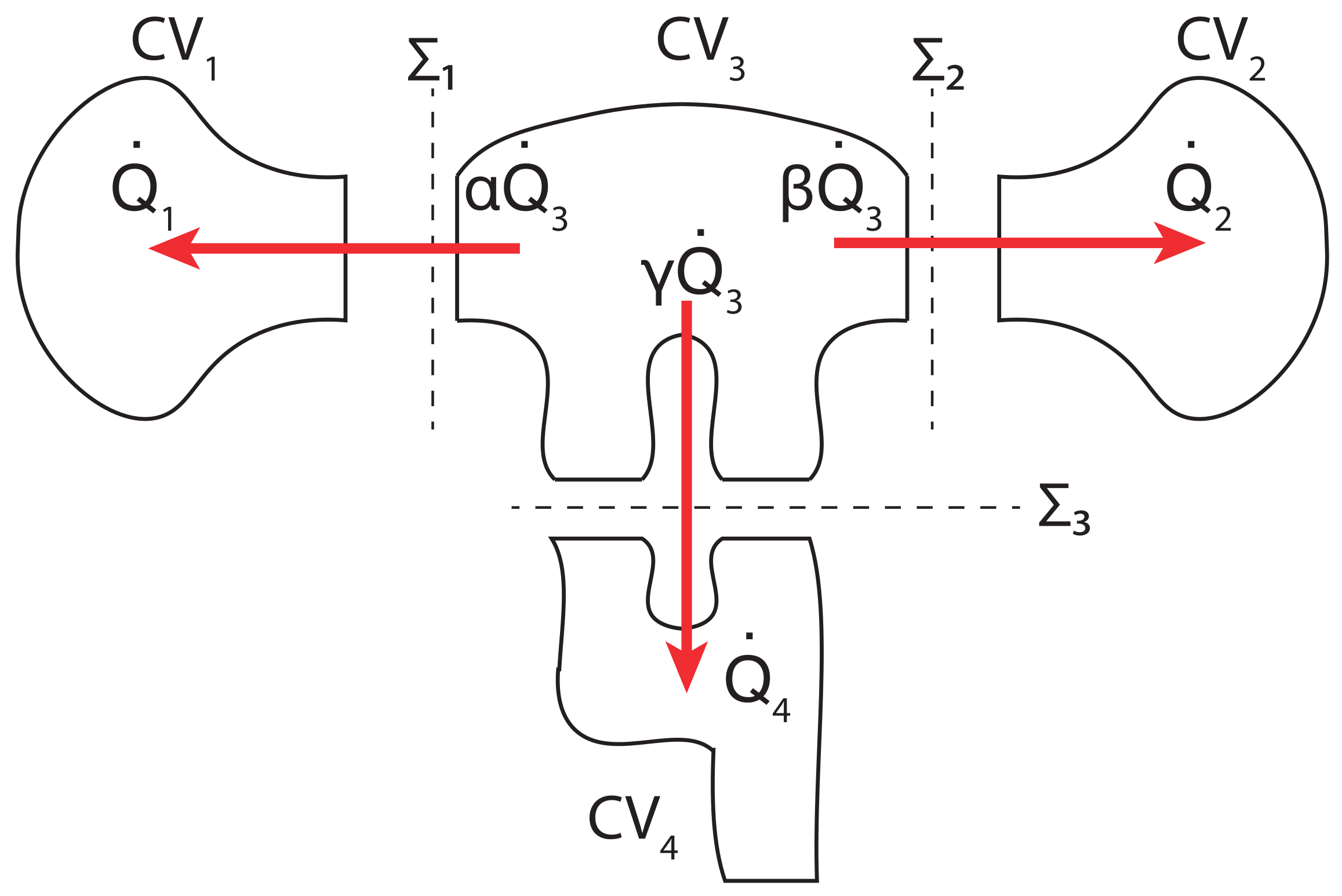
Figure 5. The variation in the amount of matter d m C V d t for each control volume and the mass flow rates m ˙ between them.
Lubricants 10 00095 g005
It is then possible to apply this mass balance to each control volume of the tribological system. In the case of the first and the second body, we obtain:
d m C V i d t = m ˙ i s for i = 1 , 2 .
This means that the variation in the mass of the two first bodies d m C V i d t corresponds to the flow of matter out to the third body, m i s ˙ . With the third body, the change in matter, otherwise known as the internal flow rate, is:
d m C V 3 d t = m ˙ 3 e 1 + m ˙ 3 e 2 + m ˙ 3 e 3 m ˙ 3 s .
For CV4, the mass balance is such that:
d m C V 4 d t = m ˙ 4 e m ˙ 4 s 1 m ˙ 4 s 2 .
By assumption, the mass of the fourth control volume does not vary:
d m C V 4 d t = 0 ,
so,
m ˙ 4 e m ˙ 4 s 1 m ˙ 4 s 2 = 0 .
As a fraction of the material lost by the third body can be reintroduced into the contact by recirculation, it may be convenient to introduce a mass wear rate, κ , and a complementary mass recirculation rate, 1 κ , with:
m ˙ 4 s 2 = κ m ˙ 4 e
m ˙ 4 s 1 = ( 1 κ ) m ˙ 4 e .
Some inflows from one control volume can be identified as outflow from another control volume, thus:
m ˙ i s = m ˙ 3 e i for i = 1 , 2 .
Equation (14) represents the matter lost by the first bodies and which feeds the third one. Moreover, the outflow of matter that comes out from the third body m ˙ 3 s is equivalent to the inflow that comes in the fourth control volume m ˙ 4 e (Equation (15)).
m ˙ 3 s = m ˙ 4 e .
Then, the material that enters the third body by the inflow m ˙ 3 e 3 , due to recirculation, is associated with a fraction of material that potentially leaves the fourth control volume by the outflow m ˙ 4 s 1 (Equation (16)).
m ˙ 3 e 3 = m ˙ 4 s 1 .
It is now possible to express the flow rate of the third body as a function of the matter emitted by the first bodies, CV1 and CV2, and that lost through CV4:
d m C V 3 d t = m ˙ 1 s + m ˙ 2 s + m ˙ 4 s 1 m ˙ 4 e
= i = 1 2 m ˙ i s + ( 1 κ ) m ˙ 4 e m ˙ 4 e .
Now, the evolution of the matter constituting the third body is then expressed as a function of the matter emitted by the first bodies and the mass wear rate κ . Equation (11), leading to
d m C V 3 d t = i = 1 2 m ˙ i s κ m ˙ 4 e
= i = 1 2 m ˙ i s m ˙ 4 s 2 .
The evolution of the matter in the third body depends on the mass lost by the first bodies, m ˙ 1 s and m ˙ 2 s , and the matter lost m 4 s 2 .
Nicolas Fillot, in his thesis [27], and in his 2005 and 2007 articles [28,29] proposes a model accompanied by experiments. His work is an example of this approach’s effectiveness at describing the flow of matter during a tribological test by considering a three-body approach and so the Berthier relations (Equation (1)–(3)). These equations are found here by assessing the mass conservation in open systems.
This mass balance allows moving on to another step: the energetic study, which will consider the sharing of matter between the different elements of the tribosystem.

3. Energy Balance

Let us apply the first principle of thermodynamics to our tribological system. During a time d t , the total energy variation in a control volume CVi and associated with the total net energy balance correspond to the thermal Q i ˙ and non-thermal W i ˙ energies exchanged with the environment, i.e.:
d E C V i d t + s m ˙ i s ε i s e m ˙ i e ε i e = W i ˙ + Q i ˙ ,
with,
  • E C V i : the total energy in the i-th control volume CVi;
  • s m ˙ i s ε i s e m ˙ i e ε i e : the total net power balance, which contains the total power entering in the i-th control volume and that leaving it.
It is noted that:
  • ε i e : the total energy per unit of mass entering the i-th control volume CVi;
  • ε i s : the total energy per unit of mass leaving the i-th control volume CVi;
  • W i ˙ : the non-thermal power exchanged by the i-th control volume CVi;
  • Q i ˙ : the thermal power exchanged by the i-th control volume CVi.
With the help of the considerations made when describing the mass balance (see Section 2), this total energy balance is applied to each control volume (Figure 6). So, the total energy variation of every control volume is expressed:
  • For the first bodies:
    d E C V i d t = W i ˙ + Q i ˙ m ˙ i s ε i s .
Figure 6. The diagram represents the total energy variations for each control volume and the total energy flows between them.
Lubricants 10 00095 g006
Thus, in the first bodies, the variation of the total energy CV1 and CV2 depends on the total energy lost by the production of debris towards the third body and the thermal and non-thermal energy exchanged with its environment.
  • For the third body:
    d E C V 3 d t = W 3 ˙ + Q 3 ˙ + m ˙ 3 e 1 ε 3 e 1 + m ˙ 3 e 2 ε 3 e 2 + m ˙ 3 e 3 ε 3 e 3 m ˙ 3 s ε 3 s .
  • For the control volume, which models the interface with the external environment:
    d E C V 4 d t = W 4 ˙ + Q 4 ˙ + m ˙ 4 e ε 4 e m ˙ 4 s 1 ε 4 s 1 m ˙ 4 s 2 ε 4 s 2 .
    The non-thermal powers W i ˙ express the elastic deformation and the plastic deformation, the shear, the breakage or the rolling, i.e., all accommodation modes presented in Section 1. The index i is associated with accommodation sites, so the i-th control volume. From this we can deduce that:
    W i ˙ = j w ˙ j for i = 1 , 2 , 3 and j = 0 , 1 , 2 , 3 , 4 ,
    where w ˙ j represents the non-thermal power of a given accommodation mechanism. The index j varies from 0 to 4, according to the Denapes’ notation for the accommodation mechanisms (Table 2). Those mechanisms are identified in all control volumes, except in the fourth. Indeed, the fourth control volume schematises the external flow rate but is not considered as an accommodation site in the tribosystem.
    d E C V 4 d t = 0 and W 4 ˙ = 0 .
    Then, Equation (24) therefore becomes:
    Q 4 ˙ = m ˙ 4 s 1 ε 4 s 1 + m ˙ 4 s 2 ε 4 s 2 m ˙ 4 e ε 4 e .
It becomes helpful to consider the flow of thermal energy. An example that describes the flow of thermal energy can be found in the numerous works in the literature that deal in particular with braking. These tests are often instrumented to measure conductive or radiative heating. In work presented in 2015 by Lafon-Placette et al. [41] or Delbé et al. in 2020 [42], an experiment describes a rotating contact between two rings observed by a thermal camera. The tribological tests were coupled with an FLIR Titanium SC7000 infrared camera. This high-speed infrared camera was retrofitted with InSb sensors to follow the temperature field on the sample’s surface and around it. The thermal resolution was about 20 mK, and the acquisition frequency was 102 Hz. In Figure 7 and Figure 8, the temperature shown is not the absolute temperature, but is a difference between the measured temperature and the environment temperature T . In the sequence of images represented in Figure 7, we observe the appearance of heat flow from the interface between the two rings in contact and which progressively propagates towards the first bodies, then the sample holders.
The third body is a heat source. Indeed, the total energy coming from the relative displacement of the two first bodies is partially converted into thermal energy Q 3 . This thermal flux propagates from the third body and spreads towards the first bodies, Q 1 and Q 2 , when the third body temperature becomes higher than the temperature of the surrounding control volume and environment. In this model, it is assumed that the first two bodies are thermally isolated from the environment. Finally, a fraction of the thermal energy Q 4 leaves the third body towards the outside environment, VC4. So,
i = 1 4 Q i ˙ = Q 1 ˙ + Q 2 ˙ + Q 3 ˙ + Q 4 ˙ = 0 ,
where Q 3 ˙ is negative. Q 1 ˙ , Q 2 ˙ and Q 4 ˙ are positive. The thermal energy Q 3 is thus given up by the third body and shared towards the first two bodies and the external environment:
Q 3 ˙ = Q 1 ˙ Q 2 ˙ Q 4 ˙ < 0 .
As the third body shares the thermal power with the other control volumes, partition coefficients can indicate the heat flow distribution. We will note α , the partition coefficient between the first and third body, β between the second and third body and γ between the third body and the environment.
Thus, the thermal power transmitted from the third body to the first body is written (Figure 9):
Q 1 ˙ = α Q 3 ˙ > 0 .
That of the third body to the second body:
Q 2 ˙ = β Q 3 ˙ > 0 .
Finally, the one transmitted from the body to the surrounded environment:
Q 4 ˙ = γ Q 3 ˙ > 0 .
In this way, all thermal powers may be expressed as a function of the heat source Q 3 ˙ .
In addition, correspondences between the incoming total energy flows and outgoing total energy flows of the juxtaposed control volumes can also be stated:
  • Between the two first bodies and the third body, it is established that:
    m ˙ i s ε i s = m ˙ 3 e i ε 3 e i for i = 1 , 2 .
    In other words, the flow of total energy transported by the matter from the first bodies enters the third body;
  • Not forgetting the flow of material that can return from the external environment to the third body through the recirculation flow:
    m ˙ 3 e 3 ε 3 e 3 = m ˙ 4 s 1 ε 4 s 1 ;
  • It is also necessary to take into account the flow of total energy transported by the material lost by the third body and which is received by the external environment:
    m ˙ 3 s ε 3 s = m ˙ 4 e ε 4 e .
It is now possible to express the variation of the total energy of the third body as a function of the flows of matter exchanged with the surrounding control volumes:
d E C V 3 d t = W 3 ˙ + Q 3 ˙ + i = 1 2 m ˙ i s ε i s + m ˙ 4 s 1 ε 4 s 1 m ˙ 4 e ε 4 e .
Based on Equations (27) and (29),
m ˙ 4 s 1 ε 4 s 1 m ˙ 4 e ε 4 e = Q 4 ˙ m ˙ 4 s 2 ε 4 s 2
and
Q 4 ˙ = Q 1 ˙ Q 2 ˙ Q 3 ˙ < 0 ,
then,
d E C V 3 d t = i = 1 2 m ˙ i s ε i s Q i + W 3 ˙ m ˙ 4 s 2 ε 4 s 2 .
In the third body, the variation of the total energy comes from the gain of matter by the first bodies: i = 1 2 m ˙ i s . Some of this energy returns as heat to the first and second bodies: i = 1 2 Q i . A fraction of energy W 3 ˙ participates in accommodation modes such as elastic or plastic deformation, fracture, shear or rolling. The remainder can definitely escape from the contact: m ˙ 4 s 2 ε 4 s 2 .
In Figure 8, the sequence of images shows again that realized by Lafon-Placette et al., with the field of view closer to the contact [41,42]. Due to the instability of the system, several small debris is emitted to the outside. Particles are observed to emerge from the interface and cool in the environment. This is a clear case of total energy loss through material flow and is described by Equation (39) by the term m ˙ 4 s 2 ε 4 s 2 .

4. Discussion

An energetic approach to a tribological circuit is described in this article. It allows expressing a mass balance and an energy balance for a three-body tribological system.
The mass balance equations are obtained from a thermodynamic approach to open systems. These equations are similar to Berthier’s and have been experimentally validated by Fillot. Experimental validation of the energy balance is a challenge. Often some tests measure thermal energy by radiation and conduction [43,44,45]. Some research teams complete these acoustic measurements [46]. Studies employing acoustic emission coupled with in situ or post-mortem observations of contact can also be found in the work of M. Yahiaoui and colleagues [47,48,49]. Nevertheless, no study simultaneously presents exhaustive and quantitative measurements of all these energies. This is a scientific challenge that requires an experimental device that would allow exhaustively gathering measurements of the different forms of energy involved qualitatively and quantitatively. To understand it correctly would require a tribometer that would simultaneously measure thermal energy in the contact and its environment and elastic and plastic deformation energy, breaking energy, acoustic energy, chemical reactions, luminous energy (triboluminescence) and electrical energy (triboelectricity).
Beyond this, the proposed model has limits. Neither the experimental device (tribometer) nor the screens have been assessed to simplify the representation. This consideration would require adding suitable control volumes to the model. In the case of the experimental device, the control volume would not provide matter to the third body but would be able to contribute to the accommodation mechanisms and thermal energy dissipation. In the case of the screens, it would be appropriate to include a control volume with a limited amount of matter, which would flow into the third body and could be fully consumed in the first moments of friction.
Furthermore, the model chosen in the article does not consider a possible interaction of the first bodies with the external environment. Although, in some situations, these phenomena play an essential role [43,50], heat conduction to the sample holders and thus to the tribometer is neglected, as well as thermal radiation from the control surfaces, thermal convection and even chemical reactivity with the environment. The consideration of an entry of matter into the first bodies would be required. Moreover, the dissipation of energy in the form of heat from the first bodies to the external environment (or through the experimental device) may be necessary. The model could also be refined by allowing chemical reactions. For example, one could refer to Ilia Prigogine’s work to describe this point [51].
In addition, the initial heat source is arbitrarily introduced into the energy balance. This choice, evident from a phenomenological point of view, is questionable since it does not explain the origin of dissipation. An approach using the second principle of thermodynamics should produce a more robust model.
Finally, this work will be extended in the future by tackling simplifying assumptions. Indeed, the model could be improved by considering the action of the screens, the influence of the device, the action of the environment and chemical reactions. Another extension of this work will consist of experimentally validating the model’s energy part by designing tests allowing the measurement, simultaneously, exhaustively and quantitatively, of all the energies involved.

5. Conclusions

In conclusion, this work presents a model inspired by the triplet and the tribological circuit with a thermodynamic approach to open systems. We propose the conservation of mass equations considering the interaction between the first body, the third body and the external environment. A system of equations expressing the energy balance is deduced from the conservation of matter equations. This energy balance explicitly expresses the interdependence of material flows, and thermal and non-thermal energy flows between the different parts of the tribosystem.

Funding

This research received no external funding.

Institutional Review Board Statement

Not applicable.

Informed Consent Statement

Not applicable.

Data Availability Statement

The data presented in this study are available on request from the corresponding author.

Acknowledgments

I thank Jean Denape, Malik Yahiaoui, Philippe Fillatreau and Jean-Yves Paris for the fruitful discussions on this subject.

Conflicts of Interest

The author declares no conflict of interest.

References

  1. Dowson, D. History of Tribology; Professional Engineering Publishing: London, UK, 1998. [Google Scholar]
  2. Dowson, D. Elastohydrodynamic and micro-elastohydrodynamic lubrication. Wear 1995, 190, 125–138. [Google Scholar] [CrossRef]
  3. Frêne, J.; Arghir, M.; Constantinescu, V. Combined thin-film and Navier–Stokes analysis in high Reynolds number lubrication. Tribol. Int. 2006, 39, 734–747. [Google Scholar] [CrossRef]
  4. Medwell, J.O.; Gethin, D.T.; Taylor, C. A finite element analysis of the Navier-Stokes equations applied to high speed thin film lubrication. J. Tribol. 1987, 109, 71–76. [Google Scholar] [CrossRef]
  5. Patel, R.; Khan, Z.A.; Saeed, A.; Bakolas, V. A Review of Mixed Lubrication Modelling and Simulation. Tribol. Ind. 2022, 44, 150. [Google Scholar] [CrossRef]
  6. Holey, H.; Codrignani, A.; Gumbsch, P.; Pastewka, L. Height-Averaged Navier–Stokes Solver for Hydrodynamic Lubrication. Tribol. Lett. 2022, 70, 36. [Google Scholar] [CrossRef]
  7. Deshmukh, K.; Warudkar, V. Thermohydrodynamic Analysis of Journal Bearing Using Non-newtonian Lubricants. In Advances in Mechanical Engineering and Technology; Springer: Singapore, 2022; pp. 97–106. [Google Scholar]
  8. Doumeng, M.; Ferry, F.; Delbé, K.; Mérian, T.; Chabert, F.; Berthet, F.; Marsan, O.; Nassiet, V.; Denape, J. Evolution of crystallinity of PEEK and glass-fibre reinforced PEEK under tribological conditions using Raman spectroscopy. Wear 2019, 426, 1040–1046. [Google Scholar] [CrossRef] [Green Version]
  9. Doumeng, M. Étude des Propriétés Intrinsèques et Tribologiques des Composites à Matrice PEEK Chargés de Renforts Micro/Nanométriques. Ph.D. Thesis, INPT, Toulouse, France, 2021. [Google Scholar]
  10. Zhang, X.; Zhang, Y.; Jin, Z. A review of the bio-tribology of medical devices. Friction 2021, 10, 4–30. [Google Scholar] [CrossRef]
  11. Wagner, R.M.; Maiti, R.; Carré, M.J.; Perrault, C.M.; Evans, P.C.; Lewis, R. Bio-tribology of vascular devices: A review of tissue/device friction research. Biotribology 2021, 25, 100169. [Google Scholar] [CrossRef]
  12. Zheng, Y.; Bashandeh, K.; Shakil, A.; Jha, S.; Polycarpou, A.A. Review of dental tribology: Current status and challenges. Tribol. Int. 2022, 166, 107354. [Google Scholar] [CrossRef]
  13. Jones, W.R.; Jansen, M.J. Tribology for space applications. Proc. Inst. Mech. Eng. Part J. Eng. Tribol. 2008, 222, 997–1004. [Google Scholar] [CrossRef]
  14. Bashandeh, K.; Tsigkis, V.; Lan, P.; Polycarpou, A.A. Extreme environment tribological study of advanced bearing polymers for space applications. Tribol. Int. 2021, 153, 106634. [Google Scholar] [CrossRef]
  15. Orozco Gomez, S.; Delbé, K.; Benitez, A.; Paris, J.Y.; Denape, J. High temperature tribological behaviour of metal matrix composites produced by SPS. Key Eng. Mater. 2021, 482, 89–100. [Google Scholar] [CrossRef] [Green Version]
  16. Delbé, K.; Orozco Gomez, S.; Carrillo Mancuso, J.M.; Paris, J.Y.; Denape, J. Tribological behaviour of stellite matrix composites for high temperatures applications. Key Eng. Mater. 2012, 498, 89–101. [Google Scholar] [CrossRef] [Green Version]
  17. Lafon-Placette, S.; Delbé, K.; Denape, J.; Ferrato, M. Tribological characterization of silicon carbide and carbon materials. J. Eur. Ceram. Soc. 2015, 35, 1147–1159. [Google Scholar] [CrossRef] [Green Version]
  18. Zeng, Q.; Ning, Z. High-temperature tribological properties of diamond-like carbon films: A review. Rev. Adv. Mater. Sci. 2021, 60, 276–292. [Google Scholar] [CrossRef]
  19. Gopinath, V.M.; Arulvel, S. A review on the steels, alloys/high entropy alloys, composites and coatings used in high temperature wear applications. Mater. Today Proc. 2021, 43, 817–823. [Google Scholar] [CrossRef]
  20. Nyberg, E.; Llopart i Cervelló, D.; Minami, I. Tribology in space robotic actuators: Experimental method for evaluation and analysis of gearboxes. Aerospace 2021, 8, 75. [Google Scholar] [CrossRef]
  21. Bowden, F.P.; Tabor, D. The Friction and Lubrication of Solids; Oxford University Press: New York, NY, USA, 2001. [Google Scholar]
  22. Godet, M. The third-body approach: A mechanical view of wear. Wear 1984, 100, 437–452. [Google Scholar] [CrossRef]
  23. Berthier, Y. Mécanismes et Tribologie. Ph.D. Thesis, INSA, Lyon, France, 1988. [Google Scholar]
  24. Berthier, Y.; Vincent, L.; Godet, M. Velocity accommodation sites and modes in tribology. Eur. J. Mech. A/Solids 1992, 11, 35–47. [Google Scholar]
  25. Denape, J.; Berthier, Y.; Vincent, L. Wear Particle Life in a Sliding Contact Under Dry Conditions: Third Body Approach Fundamentals of Tribology and Bridging the Gap Between Macro and Micro-Nanoscale. NATO Sci. Ser. II 2001, 10, 393–411. [Google Scholar]
  26. Denape, J. Third Body Concept and Wear Particle Behaviour in Dry Sliding Friction. Key Eng. Mater. 2015, 640, 1–12. [Google Scholar] [CrossRef] [Green Version]
  27. Fillot, N. Étude Mécanique de L’usure: Modélisation par Éléments Discrets des Débits de Troisième Corps Solide. Ph.D. Thesis, INSA, Lyon, France, 2004. [Google Scholar]
  28. Fillot, N.; Iordanoff, I.; Berthier, Y. Simulation of wear through mass balance in a dry contact. J. Tribol. 2005, 127, 230–237. [Google Scholar] [CrossRef]
  29. Fillot, N.; Iordanoff, I.; Berthier, Y. Wear modeling and the third body concept. Wear 2007, 262, 949–957. [Google Scholar] [CrossRef]
  30. Dragon-Louiset, M. Modèles micromécaniques de l’interface d’un système tribologique dans une approche thermodynamique de l’usure continue. Méc. Ind. 2000, 1, 37–42. [Google Scholar] [CrossRef]
  31. Dragon-Louiset, M. On a predictive macroscopic contact-sliding wear model based on micromechanical considerations. Int. J. Solids Struct. 2001, 38, 1625–1639. [Google Scholar] [CrossRef]
  32. Czichos, H. Tribology: A Systems Approach to the Science and Technology of Friction, Lubrication, and Wear; Elsevier: Amsterdam, The Netherlands, 2009; Volume 1. [Google Scholar]
  33. Lyashenko, I.A.; Khomenko, A.V.; Metlov, L.S. Thermodynamics and kinetics of boundary friction. Tribol. Int. 2011, 44, 476–482. [Google Scholar] [CrossRef] [Green Version]
  34. Maciąg, M. Thermodynamic model of the metallic friction process. J. Tribol. 2010, 132, 031603. [Google Scholar] [CrossRef]
  35. Maciąg, M. Specific Heat of Tribological Wear Debris Material. J. Tribol. 2015, 137, 031601. [Google Scholar] [CrossRef]
  36. Banjac, M.; Vencl, A.; Otović, S. Friction and Wear Processes—Thermodynamic Approach. Tribol. Ind. 2014, 36, 341–347. [Google Scholar]
  37. Fedorov, S.V. Energy Balance of Friction and Friction Coefficient in Energetical Interpretation. Tribol. Ind. 2015, 37, 380–389. [Google Scholar]
  38. Fedorov, S.V. Structural-Energy Interpretation of a Tribosystem. J. Frict. Wear 2021, 42, 117–123. [Google Scholar] [CrossRef]
  39. Fedorov, S.V. Analysis of the Energy Balance of Friction on the Rolling Contact. Tribol. Ind. 2021, 43, 283–297. [Google Scholar] [CrossRef]
  40. Bejan, A. Evolution in thermodynamics. Appl. Phys. Rev. 2017, 4, 011305. [Google Scholar] [CrossRef]
  41. Lafon-Placette, S. Performances Tribologiques d’un Carbure de Silicium Pour Paliers D’étanchéité Dynamique Fonctionnant en Conditions Sévères. Ph.D. Thesis, INPT, Toulouse, France, 2015. [Google Scholar]
  42. Delbé, K.; Lafon-Placette, S.; Ferrato, M.; Welemane, H.; Denape, J. Influence des imprégnations du carbone-graphite sur les performances tribologiques d’un couple de frottement C/SiC. In Proceedings of the 24th Congrès Français de la Mécanique, Nantes, France, 26–30 August 2019. [Google Scholar]
  43. Kasem, H.; Brunel, J.F.; Dufrenoy, P.; Desplanques, Y.; Desmet, B. Monitoring of temperature and emissivity during successive disc revolutions in braking. Proc. Inst. Mech. Engin. Part J. Eng. Tribol. 2012, 226, 748–759. [Google Scholar] [CrossRef]
  44. Nosko, O.; Tsybrii, Y. Inverse determination of sliding surface temperature based on measurements by thermocouples with account of their thermal inertia. Tribol. Int. 2021, 164, 107200. [Google Scholar] [CrossRef]
  45. Nassef, M.G.A.; Soliman, M.; Nassef, B.G.; Daha, M.A.; Nassef, G.A. Impact of Graphene Nano-Additives to Lithium Grease on the Dynamic and Tribological Behavior of Rolling Bearings. Lubricants 2022, 10, 29. [Google Scholar] [CrossRef]
  46. Lai, V.V.; Paszkiewicz, I.; Brunel, J.F.; Dufrénoy, P. Squeal occurrence related to the tracking of the bearing surfaces on a pin-on-disc system. Mech. Syst. Signal Process. 2022, 165, 108364. [Google Scholar] [CrossRef]
  47. Jlaiel, K.; Yahiaoui, M.; Paris, J.Y.; Denape, J. Acoustic signature identification of damage and wear mechanisms in a steel/glass sliding contact. Proc. Inst. Mech. Engin. Part J. Eng. Tribol. 2021, 13506501211040599. [Google Scholar] [CrossRef]
  48. Jlaiel, K.; Yahiaoui, M.; Paris, J.Y.; Denape, J. Tribolumen: A Tribometer for A Correlation Between AE Signals and Observation of Tribological Process in real-time—Application to a dry steel/glass reciprocating sliding contact. Lubricants 2020, 8, 47. [Google Scholar] [CrossRef] [Green Version]
  49. Yahiaoui, M.; Marconnet, M.; Jlaiel, K.; Paris, J.Y.; Denape, J. Acoustic Emission Characterization of Transgranular Cracks in WC–Co Cemented Carbides During a One-way Scratch. Tribol. Lett. 2021, 69, 1–8. [Google Scholar] [CrossRef]
  50. Fouvry, S. Fretting wear analysis through a mechanical friction energy approach: Impact of contact loadings and ambient conditions. In European Federation of Corrosion (EFC) Series, Mechanical and Electro-Chemical Interactions Under Tribocorrosion; Ponthiaux, P., Celis, J.-P., Eds.; Woodhead Publishing: Sawston, Cambridge, UK, 2021; pp. 131–167. [Google Scholar]
  51. Prigogine, I. Introduction à la Thermodynamique des Processus Irréversibles: Introduction to Thermodynamics of Irreversible Processes; Dunod: Paris, France, 1968; pp. 1–13. [Google Scholar]
Figure 1. Tribological triplet and tribological circuit.
Lubricants 10 00095 g001
Figure 2. Accommodation sites according to Berthier’s (left) or Denape’s (right) notations.
Lubricants 10 00095 g002
Figure 3. The control volumes and the control surfaces. Two control volumes CV1 and CV2 represent the two first bodies. The central one CV3 is the third body. Another control volume, CV4, depicts the interface between the third body and the environment. Σ 1 , Σ 2 and Σ 3 are the control surface that interface the control volumes.
Lubricants 10 00095 g003
Figure 4. The inflows and outflows of each control volume.
Lubricants 10 00095 g004
Figure 7. Heat flux measured by thermal radiation using an infrared camera. Two rings embedded in sample holders slide against each other ( F N = 250 N and V = 0.5 m/s). The upper ring is made of graphite, while the lower ring is made of silicon carbide. We note the heat source at the interface between the two rings, which increases progressively towards the first bodies and even extends into the device. The temperature rise is of the order of 45 K compared to the temperature of the environment T . The flux, and so the partition coefficients, are unequal between carbon and silicon carbide. The former has a lower conductivity than the latter [41,42].
Lubricants 10 00095 g007
Figure 8. Debris emission. An instability occurred during the test. The interface emits debris into the environment. The dotted circles surround the debris emitted from the interface. These are hot spots that disperse into the outside environment while cooling. The definitive loss of matter (wear) is accompanied by a loss of total energy [41,42].
Lubricants 10 00095 g008
Figure 9. Heat dissipation in the tribological system.
Lubricants 10 00095 g009
Table 1. Sites of energy dissipation, and accommodation modes proposed by Y. Berthier.
SiteNotationModeNotation
Mechanical deviceS0Elastic deformationM1
First bodyS1RuptureM2
Screen 1S2ShearM3
Third bodyS3RollingM4
Screen 2S4
Second BodyS5
Table 2. Sites of energy dissipation, and accommodation modes proposed by J. Denape.
SiteNotationModeNotation
Mechanical deviceS0Elastic deformationM0
First bodyS1Plastic deformationM1
Second BodyS2RuptureM2
Third bodyS3ShearM3
Screen 1S4RollingM4
Screen 2S5
Publisher’s Note: MDPI stays neutral with regard to jurisdictional claims in published maps and institutional affiliations.

