Abstract
The coefficient of friction (COF) is an important parameter when evaluating brake system performance. It is complex to predict friction due to its dependence on parameters, such as sliding velocity, contact pressure, temperature, and friction material mixtures. The aim of this work is to evaluate the macroscopic COF of a disc brake system under specific braking conditions by a meso-scale approach, using a cellular automaton simulation where the friction material mixture is modelled starting from its basic components. The influence of the local components in contact is taken into account. Simulated COF values are in line with the experimental values.
1. Introduction
The coefficient of friction (COF) is one of the core parameters to describe a brake system performance. A mechanical brake system transforms the kinetic energy of the vehicle into frictional heat. This is done by pushing two pads against a rotating disc by one or more pistons through brake fluids. In this way, the frictional force is generated, and the vehicle slows down. The braking force depends on the COF, which is strongly affected by the pads-to-disc contact interface situation in terms of local contact pressure, sliding velocity, temperature [1,2,3,4,5,6,7], and friction material local ingredient in contact [8]. Kumar and Bijwe conducted a COF analysis of sensitivity to operating variables for a Non–Asbestos Organic (NAO) friction material. Its mixture included brass, copper, and iron fibres which resulted in different COF values under the same loads. Tests were conducted with three different velocities under three different pressures, resulting in a matrix of nine total conditions. Due to the difference in terms of COF response due to different reinforcing fibres, it is important to simulate the effect of fibre type on the COF. In this way, the estimation of the macroscopic COF of a disc brake system will be more accurate considering its dependence on the ingredients in contact. The local contact pressure depends on how the pad-to-disc interface is set, which is in turn influenced by calliper and disc displacements, their geometric mesoscopic features, and wear. The local sliding velocities are directly related to the disc rotational speed.
Several authors [9,10,11,12,13] have experimentally studied the pads-to-disc contact in order to explain the main physical phenomena behind the measured COF. Eriksson et al. [9] explained the wear process, on a mesoscopic scale, that takes place in pads-to-disc contact interface. In the friction material mixture, there are metal fibres and/or hard particles which carry the majority of the load and form stable primary plateaus. Wear particles, originating from both the pad and disc debris, can flow in the gaps between primary plateaus and stack up against the primary plateaus, creating secondary plateaus. This formation process of the secondary plateau has a large influence on the contact area [10]. The increasing secondary plateaus will decrease the contact pressure and affect the COF [11]. Österle et al. [12] investigated the chemical and structural changes on the pad surface after testing from nanoscopic point of view, mainly by scanning and transmission electron microscopy and surface analytical techniques. They observed the presence of a third body, which is a mix of all constituents from the pad and iron oxides from the disc. Primary contact areas are made of quartz crystals, whilst the major wear comes from the delamination of filler particles and the local degradation of phenolic resin during asperity heating. Ostermeyer [13] also demonstrates that there are primary plateaus in the pads-to-disc contact area and the wear is determined by an equilibrium of flow of growing and destruction of hard patches on the contact surface. These patches and microscopic processes have an influence on the macroscopic friction and wear behaviour of the brake system.
Several disc brake simulations based on different theoretical approaches have been developed in order to investigate different phenomena. Focusing on cooling, a Computational Fluid Dynamics (CFD) approach is used [14,15,16]. In order to study the macroscopic tribology performance of disc brakes, a Finite Element Analysis (FEA) approach is commonly used to evaluate the contact pressure distribution and wear [17,18,19,20], to estimate the global COF [11] and the airborne particle emissions [20,21,22]. However, a conventional FEA approach is unable to investigate the detailed phenomena in the pad-to-disc contact interface because the destruction and formation of plateaus usually occur in a size scale of 50 µm–500 µm [23]. For this reason, Cellular Automaton (CA) approaches could be used to evaluate the mesoscopic contact distribution [24,25,26,27,28,29,30]. To better understand the particle flow, the plateau dynamics, the tribo-film, and third body formation, nano-scale simulations based on a moving cellular automaton approach (MCA) have been developed by different authors [31,32,33,34].
Focusing on the CA approach, with the experimental observations in mind, Müller and Ostermeyer [24] developed a two-dimensional CA model of the boundary layer and extended it to describe the topography in three dimensions. Recently, Ostermeyer et al. [30] expanded the standard CA approach into an abstract cellular automaton model that takes into account the system’s load history to model the patch coverage state of the entire brake pad surface. Multi-body techniques are combined with the classical grid-base CA and integrated into realistic three-dimensional brake models, where the dynamics of the brake system are considered together with a confirmed wear debris output model. In line with idea exposed in [24], Wahlström et al. [27,28,29] have developed a mesoscopic scale approach using CA theory, which is able to simulate and predict macroscopic COF, wear, and particle emissions for a certain number of braking. Simulation results have shown a promising correlation with the inertia dynamometer bench experimental measurements. Wahlström [29] also investigated the brake pad properties on the friction and wear emissions, using a full factorial design through a simplified version of his CA approach. The disc has been regarded as a rigid body and the temperatures of the pad and the disc have been neglected. These simplifications are needed to study how the COF and wear emissions vary depending on different factors in a large number of braking. The results of the simulation show that a stable mean COF is due to a stable third body, a high specific wear, and a relatively high amount of metal fibres. Riva et al. [35] developed a multi-scale simulation approach combining CA, FEA, and Thermal-CFD approaches with outputs from inertia brake dyno bench tests to investigate the effect of changing copper fibres into steel fibres on the local contact temperature. Ricciardi et al. [36], starting from a semi-empirical model based on the work of Ostermeyer [37], developed a simulation methodology, parametrized and tested for three different brake systems, in which every parameter needs to be calibrated according to the experimental tests. In this model, CA theory and artificial neural networks are presented. The model showed a good representation of the experimental COF.
The pad friction material commonly used in passenger cars is a composite material. In its formulation four macro material families can be recognized: binder, reinforcing fibres, fillers, and frictional additives [38]. The binder is a polymer-based resin and binds the ingredients of the brake pad together. The reinforcing fibres (e.g., brass, steel, copper, ceramic) carry most of the load and act as a support for the formation of plateau from wear debris. Fillers are used to reduce costs and to modify some pad properties, whilst frictional additives affect the wear and COF. Because the copper wear debris generated from brake events is toxic to the environment, Environmental Protection Agency (EPA) and automotive industries have started the Copper-Free Brake Initiative [39] with the aim to eliminate the presence of copper in friction materials. In this way, a new category of friction pad named “Cu-Free” or “Eco-friendly” has been developed [40,41,42,43,44,45,46,47]. Menapace et al. [48] showed that using barite in the friction pad mixture to replace copper, a stable friction layer can be equally obtained.
It is known from the literature [49,50,51] that the pad friction material mixture has an impact on the COF. Any changes in a single component in the pad material mixture in terms of type or amount can result in completely different friction behaviour [49,50,51]. The influence of different pad material mixtures on the COF is usually evaluated with experiments [49,50,51] where real brake pads must be produced, which is relatively time-consuming and costly. There is a lack of simulation approaches in the literature regarding the pad friction material mixture. A simulation tool able to predict COF behaviour under certain braking cycles and takes into account the friction material composition could be useful in the brake industries in order to avoid production of friction pad prototypes, satisfying the need for greener and more sustainable production.
The aim of this work is to evaluate the macroscopic COF of a disc brake system under certain braking cycles by a meso-scale approach where the friction material mixture is modelled taking into account the raw materials in varied formulation. This is done by starting from a friction material characterization derived from literature data. A CA based simulation is able to consider the influence of the local components in contact and to predict the COF of a disc brake system. The simulated COF values are compared with inertia dyno bench tests to investigate the validity of the simulation approach.
2. Simulation Approach
The main idea of the simulation approach is to develop a CA methodology to predict the macroscopic COF during braking based on friction pv-maps for the metal fibres in friction mixtures. Friction pv-maps are the core input of the simulation approach since they define the frictional behaviour of the pad fibre materials. Friction pv-maps for different metal fibres and pressure–velocity (pv) conditions can be created from the output of tribometer tests. An overview of the simulation approach is presented in Figure 1. First, tribometer tests are run to define friction pv-maps of metal fibres and inert filler (box-1). The output of a tribometer study presented in literature [8] focusing on the influence of the amount of metal fibres, contact pressure, and sliding speed on the friction is used as fibres and inert filler friction pv-maps in the present work. Second, fibres friction pv-maps are implemented in a CA simulation tool that is setup using experimental inputs and boundary conditions. Then, simulated and experimental results are compared (box-2). When this is done, the calibrated CA simulation tool is used to estimate the macroscopic friction for two commercial pad friction materials with different metal fibres composition (box-3). Finally, the macroscopic simulated friction for the two types of pads is compared with measurements from inertia dyno bench tests (box-4). Each step in the simulation approach is explained in detail in the following sub-sections.
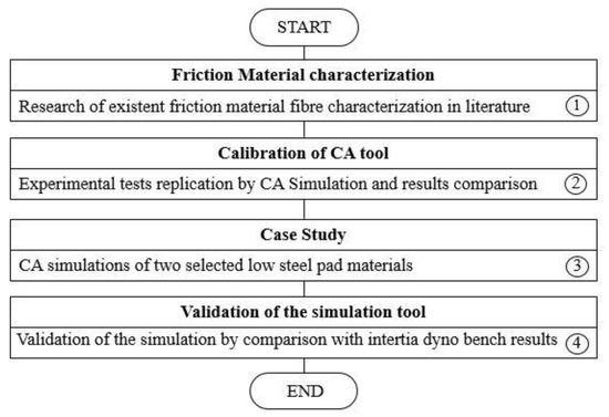
Figure 1.
An overview of the simulation methodology.
2.1. Input Friction Maps
The result presented by Kumar et al. [8] is used as input friction maps in the present work. Kumar et al. [8] experimentally investigated the influence of three metallic fibres (brass, copper, steel) and an inert filler (barite) on the measured COF. They used a NAO friction material as a base formulation. A summary of the four test samples used by Kumar et al. [8] and their materials composition is shown in Table 1.

Table 1.
Test samples composition as presented by Kumar et al. [8].
The different samples containing barite, copper, brass, and steel powders are named Ref., CP (Copper Powder), BP (Brass Powder), and IP (Iron Powder), respectively. The samples were tested using a reduced-scale prototype setup as described in [8,52]. They run the tests at three constant disc rotational speeds and three constant nominal contact pressures as presented in Table 2.

Table 2.
Test sliding velocities and nominal contact pressure as presented by Kumar et al. [8].
The most important test result was the average COF of a certain number of brake applications during one test. Four friction pv-maps (see Figure 2) were built for the four friction formulations based on the results presented by Kumar et al. [8]. Note that the Ref. friction map shows lower COF values than CP, BP, and IP. This is due to the metal powders, which are hard and abrasive, being added instead of barite, resulting in a relatively higher COF.
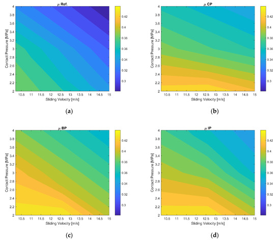
Figure 2.
Friction pv-maps: (a) Barite (µ Ref.), (b) Copper (µ CP), (c) Brass (µ BP), (d) Iron (µ IP) based on the work of Kumar et al. [8].
2.2. CA Simulation Tool
An overview of the CA simulation tool used in the present study is presented in Figure 3. The aim of this approach is to simulate the plateau dynamics in a simple way by using CA. The different blocks of the approach are summarized in the following subsections. A more detailed description of the approach can be found in the literature (see [21,22,23,24,25,26,27,28]).
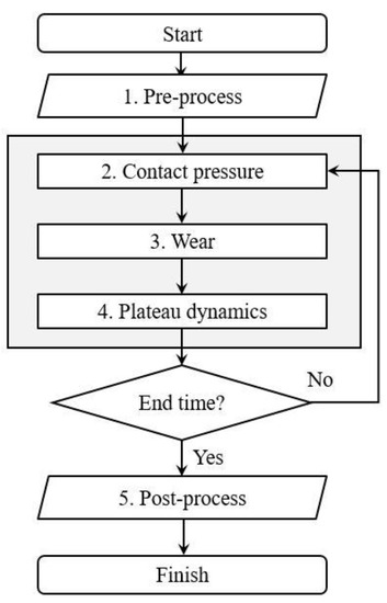
Figure 3.
CA simulation approach.
2.2.1. Pre-Process
In order to define the simulation domain, it is necessary to discretize the pad and the disc surfaces with 2D-meshes, setting up the number of the nodes in direction, which represents the angular coordinate, and the number of the nodes in r direction, which represents the radial coordinate. The simulation works in a cylindrical coordinate system (r, ). This domain is subdivided into n sub-domains in order to reduce the computational time of the simulation. This number influences the time step Δt of the simulation and needs to be chosen carefully. The time step of the simulation is calculated as follows
where n is the number of cells in each sub-domains, Δθ the angular distance between the cells, and ω the rotational velocity.
Δt = nΔθ/ω,
It is also necessary to set up the material properties, general fibres properties, the normal load acting on the pad and the disc angular velocity at the effective radius of the braking system. Initial plateau status for each cell needs to be specified. Initial conditions are:
- Disc material and pad fibres: primary plateau status;
- Pad resin: none status;
- Secondary plateaus on the pad and disc: secondary plateau status.
2.2.2. Contact Modelling
An elastic foundation model as described in [53] is used to determine the local contact pressure distribution between pad and disc surfaces. In this simulation, the disc is considered as flat and rigid and only the pad surface has been taken into account. It is possible to define the contact pressure (p) in agreement with the laws of elasticity, where the material properties of pads and disc are taken into account.
2.2.3. Wear Modelling
The local wear is calculated via numerical integration of Archard’s wear law [54] in the form proposed by Podra and Andersson [55]:
where h is the surface depth, k the specific wear rate, p the contact pressure, and r represents the radial coordinate. The assumption is that the variation of the contact pressure in a short time step is not significant during the rotation dθ. It is important to remark that the wear time step is determined by the time it takes for a point of the disc surface to pass one sub-domain on the pad. In this time interval, it is possible to consider the contact pressure as a constant. This expression is valid for primary and secondary plateau cell status while, focusing on the matrix material, its wear has a different behaviour compared to the primary and secondary plateaus one. It is reasonable to think that the resin wears out immediately as soon as it comes into contact with the disc. If there is no contact, a cell does not wear because there is no pressure.
dh/dθ = kpr,
2.2.4. Plateau Dynamics Modelling
Plateau dynamics is a complex phenomenon regarding the formation, growth and destruction of the plateaus on the pad and disc surfaces. A simple way to simulate the plateau dynamics is using CA. In this way, plateau dynamics can be modelled defining logical rules based on Von Neumann neighbourhood. Each cell can take a plateau status depending on the plateau status of the neighbourhood cells and on the calculated amount of wear escaping from each sub-domain. Eight rules have been formulated to logically describe the plateau dynamics mathematically based on experiments (e.g., [56,57]). The rules dealing with the formation of secondary plateaus can be enounced as follows. If a cell, standing in the other way to the disc rotation
- has one neighbourhood cell having plateau status to east, or
- has one neighbourhood cell having plateau status to east, one to north-east or south- east, or
- has one neighbourhood cell having plateau status to east, one to north-east and one to south-east, and there is a sufficient amount of wear to fill the gap between pad and disc, it reaches the secondary plateau status.
Rules dealing with the secondary plateaus destruction are the following. If a cell having secondary plateau status
- has no eastern neighbourhood cells
- wears down, it changes to none status
- there is no applied load on it.
Rules handling with the primary plateaus can be enounced as follows. If a cell having a primary plateau status
- has its height less than the minimum distance between pad and disc
- wears down, it changes to none status.
2.2.5. Post-Process
The main output of the meso-scale simulation is the macroscopic COF of a disc brake system, but other important outputs, such as the local contact pressure, contact area, and the initial and final pad patches and surfaces, can be evaluated.
2.3. Calibration of CA Tool
A simulation is setup with experimental inputs and boundary conditions as described by Kumar et al. [8]. The experiment concerning the inert filler (barite) is not investigated as an independent case. Instead, the experimental data for the barite test are used as the homogeneous matrix material in the simulation of the brass, iron, and copper fibres. A friction material for each type of fibre (brass, iron, and copper) is generated. One simulation is run for each velocity and pressure condition given in Table 2. In the present paper, the influence of temperature is neglected since the disc temperature is below 80 °C at the beginning of all brake applications [8].
The nominal contact pressures presented in Figure 2 are calculated with the nominal contact area of the pad. In the present work, the real contact area and resulting contact pressure are computed with the CA simulation. The ratio between the simulated real and nominal contact area is defined as the number of cells with non-zero pressures divided by the total number of cells of the model. The friction maps are updated in each simulation time step by dividing their nominal contact pressures by the aforementioned ratio to obtain the real contact pressure values. The simulation queries one of the four maps (see Figure 2) depending on the pad raw materials in contact with the disc. The barite friction map is used to describe the tribological behaviour of the homogeneous material that is not a metal fibre. The COF value for a secondary plateau is based on the assumption that it is made of 50% of raw materials and 50% of matrix material. The COF of the raw materials is a weighted average of every single raw material at the simulated pressure–velocity condition.
Comparisons between the simulated and measured COFs are shown in Figure 4 and the relative errors between the simulated and measured COFs are presented in Table 3. As seen in Figure 4, the graphs show that the simulated COF values have the same decreasing trend compared to the experimental ones although there are differences between each simulated and experimental point. The maximum relative error is 6.5%. The fibres order in terms of high to low value of COF is well replicated except for the second of the three graphs (title COF 12.6 m/s) where the simulated Fe fibre COF has a slightly higher value than the simulated Copper fibre COF, whilst in the experimental tests the opposite is noted.
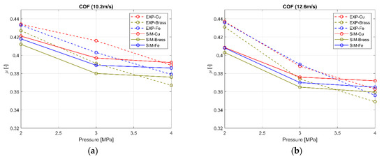
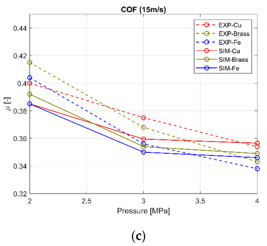
Figure 4.
Simulated COF vs. Experimental COF for a one metal fibre made friction pad: (a) 10.2 m/s, (b) 12.6 m/s, (c) 15 m/s.

Table 3.
Relative errors for each simulated and experimental points reported in Figure 4.
3. Simulation Case Study
3.1. Material and Wear Parameters
As the simulated results showed a good correlation with the experimental ones (see Section 2.3), two low steel (LS) friction materials with different mixture formulations (named as LS1 and LS2) are investigated. It is assumed that the NAO characterization results could be used to characterize two LS formulations. There are steel, brass, copper, and aramid fibres in both the NAO and LS formulation. Aramid fibres are neglected in the present study due to their low percentage of mass in the total mixture. The homogeneous material is supposed to have the properties of the barite. Fibre length values are obtained from material data sheets. Specific wear rate values (k) of the pads are considered constant during the simulation. The weight losses of the pads during experimental cycles are known, making it possible to estimate k from Equation (2). All material properties and specific wear rates are summarized in Table 4.

Table 4.
Fibres properties and specific wear rates of the two commercial low steel friction materials.
3.2. Geometry and Load Parameters
The disc is assumed to be flat and rigid to reduce computational time and temperature has not been taken into account. The fibres were randomly distributed on the pad surfaces for both the LS1 and LS2 materials, as shown in Figure 5.
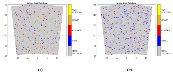
Figure 5.
Fibres distribution: (a) LS1 Friction Material, (b) LS2 Friction Material.
The discretization of the simulated domain of the pad friction material and the computational time are reported in Table 5. A brake event from 15 m/s to 10.2 m/s with a duration of 2 s and a normal load of 2.64 MPa are used in the simulation.

Table 5.
Discretization of the simulated domain and computational time.
4. Inertia Dyno Bench Tests
Low steel materials behaviour in terms of COF is evaluated by dyno bench tests under a braking from 15 m/s to 10.2 m/s, brake cylinder pressure 40 bar, and 2 s duration. The inertia dyno bench has the following setup: the brake system is assembled on a rotating shaft that moves the brake disc. An actuator controls the brake cylinder pressure and, in order to have a constant braking torque, torque feedback is necessary to regulate the pressure. The cooling of the brake system is obtained by the air coming from an inlet pipe that ensures a proper ventilation in the dyno bench structure together with an outlet pipe. The inertia dyno bench and its 3D model are presented in Figure 6. The test is executed with an inertia of 122 kgm2. To experimentally evaluate pad wear, its weight is measured before and after testing by a Sartorius balance MSE14202S (repeatability ± 0.01 g). Tests have been executed with a brake system used in a D-segment car. The most relevant characteristics of the brake system and the car are shown in Table 6. The specific wear rates for the two commercial friction material pads have been previously reported in Table 4.
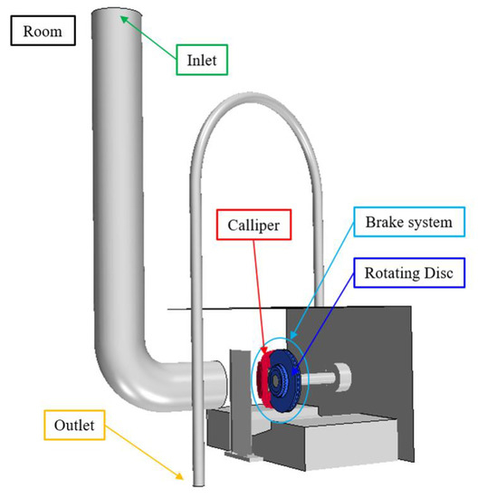
Figure 6.
3D model of the inertia dyno bench.

Table 6.
Car and front brake disc data.
5. Results
In Figure 7, the final pad patches of the two low steel materials are reported. The material with the higher value of specific wear rate (LS2) is able to generate more secondary plateaus than the one with the lower value (LS1). In Figure 8, the final pad surface topography of the two LS materials is reported. The final pad surface topography of LS2 material is smoother than the one of LS1 material. In Figure 9, the contact pressure distribution on the pad surface is shown for both LS materials. LS2 material has lower contact pressure values than LS1 material. The same order of magnitude in contact pressure is in line with the results presented by Wahlström [28].
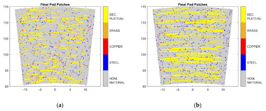
Figure 7.
Final pad patches: (a) LS1 Friction Material, (b) LS2 Friction Material.
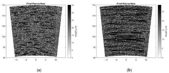
Figure 8.
Final pad surface topography: (a) LS1 Friction Material, (b) LS2 Friction Material.
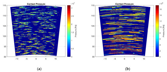
Figure 9.
Contact pressure distribution on the pad surface: (a) LS1 Friction Material, (b) LS2 Friction Material.
The results of the simulated and measured COFs for the two LS materials are presented in Figure 10. These results show that the friction material with higher specific wear rate value has higher COF values compared to the material with lower specific wear rate value. In addition, LS1 friction material has higher contact pressure values than LS2. Simulated results are qualitatively in line with the experimental ones. Moreover, the mean COF values for the whole brake events (from 0 to 2 s) are reported in Table 7.
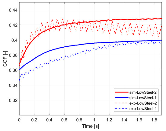
Figure 10.
Comparison between experimental and simulated COF for the two Low Steel Friction Materials.

Table 7.
Mean COF values for the whole brake events.
6. Discussion
A CA simulation tool is used to predict the macroscopic COF of a brake system during a braking cycle starting from the characterization of the raw materials of which the pad friction material is made. Two LS materials with different friction mixture and different specific wear rates have been studied. The characteristics of the basic components, i.e., the two friction materials, are referred to the experimental data presented by Kumar et al. [8]. In their study, metallic fibres (copper, brass and iron) and an inert filler (barite) have been characterized in terms of COF as a function of pressure and velocity. These kinds of metallic fibres are also present in the two LS material mixtures investigated in the present study. The barite characterization has been used to simulate the behaviour of the homogeneous material of the LS materials. The results show (Figure 10) that the simulated LS2 material has higher COF values than LS1 material, which is in line with the experimental tests conducted in an inertia dyno bench. It should be noted that there is a slight difference between the simulated COF and experimental COF. The relative error between the simulated and experimental mean COF values are 2.2% for LS1 material and 1.2% for LS2 material. Wahlström et al. [21] used a CA approach that considers the temperature and obtained a simulated COF close to experimental one. However, they did not study the influence of the material of the single fibre. Riva et al. [11] proposed a comparison between simulated and experimental COF using a FEA approach, showing a perfect correlation in the in-stop COF phase, although a positive offset that affects the simulation accuracy is seen. A drawback with the FEA approach is that it is not possible to use it in the early design phase of a new pad friction material mixture.
It can be noted from the amount of pad patches (Figure 7), pad surface topography (Figure 8), and contact pressure (Figure 9) results that all of them strongly depend on the specific wear rate. In this study, the specific wear rate has been estimated based on the pad weight loss after experimental testing. LS2 material has a value of specific wear rate higher than LS1 one, which means that a larger amount of wear can be created. Wear particles are able to stack up against the primary plateaus, in this way creating the secondary plateaus ([9,10,11,12]). It can be seen that the simulation replicates the build-up of secondary plateaus since the LS material with higher specific wear rate forms more secondary plateaus (Figure 7), resulting in the increase of contact area. For this reason, as shown in Figure 9, the contact pressure decreases. This is in line with the results presented by Wahlström [28] where the contact pressure evolution during the simulation has been reported. Comparing these results with the ones coming from the present simulation, the same order of magnitude for the contact pressure result is noted. Moreover, in [28], a CA model is used to study the contact situation between pad and disc surfaces and it is reported how contact pressure can influence friction, particle emissions, and wear. The assumption was that only steel fibre contributes to form primary plateaus and no other reinforcing fibres are considered. In the present study, the aim is to take into account all the metal fibres existing in the commercial friction material pads. It is important to remark that LS1 friction material shows higher contact pressure values than LS2 friction material, whilst its COF values are lower than the latter. Riva et al. [10] also investigated this phenomenon, which was discussed by Österle et al. [34], attributing to the thick nano-sized tribofilm created on both the contacting pad and disc surfaces. Furthermore, the higher the contact pressure, the lower the COF, since the tribofilm will be easier to shear.
In the present work, the COF values are higher for LS2 friction material, which has a smoother surface (Figure 8) than LS1 friction material. It is important to note that it is hard to observe the real contact area during experiments and therefore simulations are important. Since the measured and simulated COFs presented in Figure 10 are similar, the simulated contact area seems to be close to the real one. This also indicates that the resulting contact pressure is similar to the real one. There are other ways to verify the simulated contact pressure. It could be estimated by using a pressure sensor film [58] without rotation of the disc or indirectly by estimating the real contact area and thereafter calculating the resulting contact pressure given the normal load. One way is to use a glass disc and record the evolution of the contact area with a camera, as done Eriksson et al. [56] and Gramstadt [57]. Another way to estimate the contact area is to study the contact surface topography after testing and compare this to the simulated results.
It can be noted in Figure 10 that the simulated result for LS2 material shows an increasing trend and that the opposite can be noted for the experimental results, starting around 0.4 s. A possible explanation is that the temperature is not included in the simulation and that the real friction pad could have been affected by a local “thermal fading” during the experimental test. Another possible reason for the difference in simulated and experimental COF can be found in the evolution of the contact surface roughness during sliding. Further analysis based on more comparisons between experimental and simulated results can be useful to better investigate this behaviour.
The Winkler elastic foundation model [53] is used to estimate the contact pressure and resulting contact area in the present work. In this model, it is assumed that the conformal contact can be seen as a set of elastic bars which deform independently of each other and between which shear forces can be neglected. This approach has shown to be useful when studying dry sliding disc brake contacts on mesoscopic size scales in the past (see e.g., [21]). One way of improving this contact model is to include the stiffness dependence of surrounding elements in a similar way as presented by Müller and G.-P. Ostermeyer [24]. Furthermore, it is necessary to have a better description of the local structural properties of the contacting bodies. Input data from nanoindentation can be used to better describe the stiffness of individual fibres and the height of the foundation, which could improve the contact model in the future. In addition, the influence of local temperature on the contact stiffness can be included in the future to study thermoelastic effects [59].
Archard’s wear law is used to model the local wear of the contact surfaces. Different specific wear rates are used for the metal fibres and homogeneous material of the pad to take into account the heterogeneity of the friction material. Individual specific wear rates of the main ingredients of the friction pad mixture obtained by tribological testing can be used to improve the wear modelling in the future.
It is necessary to know the material properties of the contacting bodies to accurately simulate the complex physical phenomena occurring in the contact interfaces between the pads and disc. It is necessary to conduct several experimental tests. The contact between pad and disc is modelled with the elastic foundation model that does not take into account shear forces and with the assumption that every bar deforms independently from each other, having in this way no mutual influence between bars. In order to have good results with this simplified description of the contact situation, a calibration of parameters, such as the height of the elastic foundation, has been conducted with experimental tests.
To summarize, the results here proposed for the two LS materials seem to be promising, although they were obtained using a NAO material characterization. Aramid fibres, which are present in the two LS materials with low percentage, have been neglected. The next step will be to replicate the simulation using the two LS material characterizations as input. CA simulation can be very useful if raw materials of the friction pad mixture have been previously characterized and a database with their properties has been built. In this way, it is possible to simulate the behaviour of a very large number of friction pad mixtures without producing their prototypes. This can satisfy two important demands: the possibility to have information on the pad friction material in a very early design phase and more sustainable production.
7. Conclusions
This paper presents a meso-scale simulation approach to predict the macroscopic COF of a disc brake system under certain braking conditions, taking into account the basic components of a friction material. The simulated COF values for two different low steel pad materials have been compared with measurements performed on an inertia brake dyno bench. Major conclusions from the current study can be drawn as follows:
- The simulated COF curve during the entire brake event is similar to the experimentally measured COF curve.
- The mean value of simulated COF curve is similar to the mean value of experimental COF curve.
- There is a difference between the COF values of the two friction materials due to the different amount of primary and secondary contact plateaus as well as different contact pressures. The developed CA approach could simulate the COF difference very well.
- The simulated COF of the friction material having the lowest contact pressure values is higher than the one of the friction material having the highest contact pressure value.
It is important to remark that in this study 2D (speed + pressure) friction maps have been used that do not take into account the influence of temperature. Hence, the next step will be the development of 3D friction maps together with the implementation of the temperature variable in the simulation in order to enable the simulation to predict the macroscopic COF of a disc brake system under high temperature braking.
Author Contributions
Conceptualization, F.V., G.R., and J.W.; methodology, F.V. and G.R.; software, F.V. and G.R.; validation, F.V., G.R., and J.W.; formal analysis, F.V.; investigation, F.V., J.W., and G.R.; resources, F.V., G.R., and J.W.; data curation, F.V. and J.W.; writing—original draft preparation, F.V.; writing—review and editing, J.W., Y.L., and G.R.; visualization, F.V., J.W., and Y.L.; supervision, J.W. and Y.L.; project administration, F.V. and J.W. All authors have read and agreed to the published version of the manuscript.
Funding
This research received no external funding.
Institutional Review Board Statement
Not applicable.
Informed Consent Statement
Not applicable.
Data Availability Statement
Not applicable.
Conflicts of Interest
The authors declare no conflict of interest.
Abbreviations
| COF | Coefficient of Friction |
| CA | Cellular Automaton |
| CFD | Computational Fluid Dynamics |
| FEA | Finite Element Analysis |
| LS | Low Steel |
| NAO | Non-Asbestos Organic |
References
- Tirovic, M.; Day, A.J. Disc Brake Interface Pressure Distributions. Proc. Inst. Mech. Eng. Part D J. Automob. Eng. 1991, 205, 137–146. [Google Scholar] [CrossRef]
- Garg, B.D.; Cadle, S.H.; Mulawa, P.A.; Groblicki, P.J.; Laroo, C.; Parr, G.A. Brake Wear Particulate Matter Emissions. Environ. Sci. Technol. 2000, 34, 4463–4469. [Google Scholar] [CrossRef]
- Kukutschová, J.; Moravec, P.; Tomášek, V.; Matějka, V.; Smolík, J.; Schwarz, J.; Seidlerová, J.; Šafářová, K.; Filip, P. On airborne nano/micro-sized wear particles released from low-metallic automotive brakes. Environ. Pollut. 2011, 159, 998–1006. [Google Scholar] [CrossRef] [PubMed]
- Sanders, P.G.; Xu, N.; Dalka, T.M.; Maricq, M.M. Airborne Brake Wear Debris: Size Distributions, Composition, and a Comparison of Dynamometer and Vehicle Tests. Environ. Sci. Technol. 2003, 37, 4060–4069. [Google Scholar] [CrossRef]
- Wahlström, J.; Matejka, V.; Lyu, Y.; Söderberg, A. Contact Pressure and Sliding Velocity Maps of the Friction, Wear and Emission from a Low-Metallic/Cast-Iron Disc Brake Contact Pair. Tribol. Ind. 2017, 39, 460–470. [Google Scholar] [CrossRef] [Green Version]
- Perricone, G.; Wahlström, J.; Olofsson, U. Towards a test stand for standardized measurements of the brake emissions. Proc. Inst. Mech. Eng. Part D J. Automob. Eng. 2016, 230, 1521–1528. [Google Scholar] [CrossRef]
- Mathissen, M.; Grochowicz, J.; Schmidt, C.; Vogt, R.; zum Hagen, F.H.F.; Grabiec, T.; Steven, H.; Grigoratos, T. A novel real-world braking cycle for studying brake wear particle emissions. Wear 2018, 414–415, 219–226. [Google Scholar] [CrossRef]
- Kumar, M.; Bijwe, J. Composite friction materials based on metallic fillers: Sensitivity of µ to operating variables. Tribol. Int. 2011, 44, 106–113. [Google Scholar] [CrossRef]
- Eriksson, M.; Bergman, F.; Jacobson, S. On the nature of tribological contact in automotive brakes. Wear 2002, 252, 26–36. [Google Scholar] [CrossRef]
- Riva, G.; Perricone, G.; Wahlström, J. Simulation of Contact Area and Pressure Dependence of Initial Surface Roughness for Cermet-Coated Discs Used in Disc Brakes. Tribol. Ind. 2019, 41, 1–13. [Google Scholar] [CrossRef]
- Riva, G.; Varriale, F.; Wahlström, J. A finite element analysis (FEA) approach to simulate the coefficient of friction of a brake system starting from material friction characterization. Friction 2020, 9, 1–10. [Google Scholar] [CrossRef]
- Österle, W.; Griepentrog, M.; Gross, T.; Urban, I. Chemical and microstructural changes induced by friction and wear of brakes. Wear 2001, 251, 1469–1476. [Google Scholar] [CrossRef]
- Ostermeyer, G.P. Friction and wear of brake systems. Forsch. Im Ing. 2001, 66, 267–272. [Google Scholar] [CrossRef]
- Hacisalihoglu, Y.; Dalga, Y.B.; Akca, D.; Ergin, E.; Aydin, B. Brake Cooling Modelling & Correlation. In Proceedings of the Eurobrake, Dresden, Germany, 21–23 May 2019. [Google Scholar]
- Thuresson, A. CFD and Design Analysis of Brake Disc. Master’s Thesis, Chalmers University of Technology, Göteborg, Sweden, 2014. [Google Scholar]
- Belhocine, A.; Cho, C.D.; Nouby, M.; Yi, Y.B.; Bakar, A.R.A. Thermal analysis of both ventilated and full disc brake rotors with frictional heat generation. Appl. Comput. Mech. 2014, 8, 5–24. [Google Scholar]
- Afzal, A.; Mujeebu, A. Thermo-Mechanical and Structural Performances of Automobile Disc Brakes: A Review of Numerical and Experimental Studies. Arch. Comput. Methods Eng. 2018, 26, 1489–1513. [Google Scholar] [CrossRef]
- Soderberg, A.; Sellgren, U.; Andersson, S. Using Finite Element Analysis to Predict the Brake Pressure Needed for Effective Rotor Cleaning in Disc Brakes; SAE International: Warrendale, PA, USA, 2008. [Google Scholar]
- Valota, G.; De Luca, S.; Söderberg, A. Using a finite element analysis to simulate the wear in disc brakes during a dyno bench test cycle. In Proceedings of the Eurobrake, Dresden, Germany, 2–4 May 2017. [Google Scholar]
- Wahlström, J.; Söderberg, A.; Olander, L.; Jansson, A.; Olofsson, U. Simulation of airborne wear particles from disc brakes. SAE Tech. Pap. 2010, 268, 763–769. [Google Scholar]
- Wahlström, J. A comparison of measured and simulated friction, wear, and particle emission of disc brakes. Tribol. Int. 2015, 92, 503–511. [Google Scholar] [CrossRef]
- Riva, G.; Valota, G.; Perricone, G.; Wahlström, J. An FEA approach to simulate disc brake wear and airborne particle emissions. Tribol. Int. 2019, 138, 90–98. [Google Scholar] [CrossRef]
- Federici, M.; Perricone, G.; Gialanella, S.; Straffelini, G. Sliding Behaviour of Friction Material Against Cermet Coatings: Pin-on-Disc Study of the Running-in Stage. Tribol. Lett. 2018, 66, 53. [Google Scholar] [CrossRef]
- Müller, M.; Ostermeyer, G. A Cellular Automaton model to describe the three-dimensional friction and wear mechanism of brake systems. Wear 2007, 263, 1175–1188. [Google Scholar] [CrossRef]
- Mueller, M.; Ostermeyer, G. Cellular automata method for macroscopic surface and friction dynamics in brake systems. Tribol. Int. 2007, 40, 942–952. [Google Scholar] [CrossRef]
- Ostermeyer, G.P.; Müller, M. New insights into the tribology of brake systems. Proc. Inst. Mech. Eng. Part D J. Automob. Eng. 2007, 222, 1167–1200. [Google Scholar] [CrossRef]
- Wahlström, J.; Söderberg, A.; Olofsson, U. A Cellular Automaton Approach to Numerically Simulate the Contact Situation in Disc Brakes. Tribol. Lett. 2011, 42, 253–262. [Google Scholar] [CrossRef]
- Wahlström, J. Towards a cellular automaton to simulate friction, wear, and particle emission of disc brakes. Wear 2014, 313, 75–82. [Google Scholar] [CrossRef]
- Wahlström, J. A Factorial Design to Numerically Study the Effects of Brake Pad Properties on Friction and Wear Emissions. Adv. Tribol. 2016, 2016, 8181260. [Google Scholar] [CrossRef] [Green Version]
- Ostermeyer, G.P.; Merlis, J.H. Modelling the Friction Boundary Layer of an Entire Brake Pad with an Abstract Cellular Automaton. Lubricants 2018, 6, 44. [Google Scholar] [CrossRef] [Green Version]
- Dmitriev, A.I.; Popov, V.L. Numerical modeling of processes of mass transfer in tribological contacts by the method of movable cellular automata. J. Frict. Wear 2009, 30, 12–16. [Google Scholar] [CrossRef]
- Dmitriev, A.; Österle, W.; KloβH. Numerical simulation of typical contact situations of brake friction materials. Tribol. Int. 2008, 41, 1–8. [Google Scholar] [CrossRef]
- Österle, W.; Kloß, H.; Urban, I.; Dmitriev, A. Towards a better understanding of brake friction materials. Wear 2007, 263, 1189–1201. [Google Scholar] [CrossRef]
- Österle, W.; Urban, I. Third body formation on brake pads and rotors. Tribol. Int. 2006, 39, 401–408. [Google Scholar] [CrossRef]
- Riva, G.; Perricone, G.; Wahlström, J. A multi-scale simulation approach to investigate local contact temperatures for commercial Cu-full and Cu-free brake pads. Lubricants 2019, 7, 80. [Google Scholar] [CrossRef] [Green Version]
- Ricciardi, V.; Augsburg, K.; Gramstat, S.; Schreiber, V.; Ivanov, V. Survey on Modelling and Techniques for Friction Estimation in Automotive Brakes. Appl. Sci. 2017, 7, 873. [Google Scholar] [CrossRef]
- Ostermeyer, G. On the dynamics of the friction coefficient. Wear 2003, 254, 852–858. [Google Scholar] [CrossRef]
- Chan, D.; Stachowiak, G.W. Review of automotive brake friction materials. Proc. Inst. Mech. Eng. Part D J. Automob. Eng. 2004, 218, 953–966. [Google Scholar] [CrossRef]
- EPA. Memorandum of Understanding on Copper Mitigation in Watershed and Waterways. 21 January 2015. Available online: https://www.epa.gov/npdes/copper-free-brake-initiative (accessed on 20 January 2022).
- Chen, H.; Paul, H.-G. Copper-Free Friction Material for Brake Pads. U.S. Patent 20130037360A1, 14 February 2013. [Google Scholar]
- Copper-Free Ceramic Type Friction Material and Preparation Method Thereof. U.S. Patent CN 101948673 B, 26 June 2013.
- Gilardi, R.; Alzati, L.; Thiam, M.; Brunel, J.F.; Desplanques, Y.; Dufrénoy, P.; Sharma, S.; Bijwe, J. Copper substitution and noise reduction in brake pads: Graphite type selection. Materials 2012, 5, 2258–2269. [Google Scholar] [CrossRef] [Green Version]
- Kumar, M.; Bijwe, J. Non-asbestos organic (NAO) friction composites: Role of copper; its shape and amount. Wear 2011, 270, 269–280. [Google Scholar] [CrossRef]
- Lee, P.W.; Filip, P. Friction and wear of Cu-free and Sb-free environmental friendly automotive brake materials. Wear 2013, 302, 1404–1413. [Google Scholar] [CrossRef]
- Schuler, L.J.; Hoang, T.C.; Rand, G.M. Aquatic risk assessment of copper in freshwater and saltwater ecosystems of South Florida. Ecotoxicology 2008, 17, 642–659. [Google Scholar] [CrossRef]
- Yun, R.; Filip, P.; Lu, Y. Performance and evaluation of eco-friendly brake friction materials. Tribol. Int. 2010, 43, 2010–2019. [Google Scholar] [CrossRef]
- Zhang, J.Z. Copper-Free Friction Material Composition for Brake Pads. U.S. Patent WO 2012159286 A1, 21 May 2011. [Google Scholar]
- Menapace, C.; Leonardi, M.; Matějka, V.; Gialanella, S.; Straffelini, G. Dry sliding behavior and friction layer formation in copper-free barite containing friction materials. Wear 2018, 398, 191–200. [Google Scholar] [CrossRef]
- Xiao, X.; Yin, Y.; Bao, J.; Lu, L.; Feng, X. Review on the friction and wear of brake materials. Adv. Mech. Eng. 2016, 8, 1–10. [Google Scholar] [CrossRef] [Green Version]
- Abadi, S.B.K.; Khavandi, A.; Kharazi, Y. The effect of steel & basalt fibers on the friction and wear behavior of composites brake pad non-asbestos. Int. J. Eng. Iran Univ. Sci. Technol. 2007, 4, 87–92. [Google Scholar]
- Abadi, S.B.K.; Khavandi, A.; Kharazi, Y. Effects of Mixing the Steel and Carbon Fibers on the Friction and Wear Properties of a PMC Friction Material. Appl. Compos. Mater. 2009, 17, 151–158. [Google Scholar] [CrossRef]
- Bijwe, J.; Kumar, M.; Gurunath, P.V.; Desplanques, Y.; Degallaix, G. Optimization of brass contents for best combination of tribo-performance and thermal conductivity of non-asbestos organic (NAO) friction composites. Wear 2008, 265, 699–712. [Google Scholar] [CrossRef]
- Söderberg, A.; Björklund, S. Validation of a simplified numerical contact model. Tribol. Int. 2008, 41, 926–933. [Google Scholar] [CrossRef]
- Archard, J.F. Contact and Rubbing of Flat Surfaces. J. Appl. Phys. 1953, 24, 981–988. [Google Scholar] [CrossRef]
- Põdra, P.; Andersson, S. Simulating sliding wear with finite element method. Tribol. Int. 1999, 32, 71–81. [Google Scholar] [CrossRef]
- Eriksson, M.; Lord, J.; Jacobson, S. Wear and contact conditions of brake pads: Dynamical in situ studies of pad on glass. Wear 2001, 249, 272–278. [Google Scholar] [CrossRef]
- Gramstadt, S. Methoden der in-situ Visualisierung der Reibzonendynamik trockenlaufender Reibpaarungen unter Erg¨anzung physikalischer und chemischer Charakterisierungen der Reibpartner. Ph.D. Thesis, Universitatsverlag Ilmenau, Ilmenau, Germany, 2015. [Google Scholar]
- Antanaitis, D.; Sanford, J. The Effect of Racetrack/High Energy Driving on Brake Caliper Performance. In Proceedings of the SAE 2006 Technical Paper Series, Detroit, MI, USA, 3–6 April 2006. [Google Scholar]
- Jang, Y.H. Transient thermoelastic contact problems for an elastic foundation. Int. J. Solids Struct. 2000, 37, 1997–2004. [Google Scholar] [CrossRef]
Publisher’s Note: MDPI stays neutral with regard to jurisdictional claims in published maps and institutional affiliations. |
© 2022 by the authors. Licensee MDPI, Basel, Switzerland. This article is an open access article distributed under the terms and conditions of the Creative Commons Attribution (CC BY) license (https://creativecommons.org/licenses/by/4.0/).