Article

Age Matters: A Comparative Study of RF Heating of Epicardial and Endocardial Electronic Devices in Pediatric and Adult Phantoms during Cardiothoracic MRI

1
Department of Biomedical Engineering, Northwestern University, Evanston, IL 60208, USA
2
Department of Radiology, Northwestern University, Chicago, IL 60611, USA
3
Division of Cardiology, Ann and Robert H. Lurie Children’s Hospital of Chicago, Northwestern University, Chicago, IL 60611, USA
4
Division of Medical Imaging, Ann and Robert H. Lurie Children’s Hospital of Chicago, Northwestern University, Chicago, IL 60611, USA
*
Author to whom correspondence should be addressed.
Diagnostics 2023, 13(17), 2847; https://doi.org/10.3390/diagnostics13172847
Submission received: 26 February 2023 / Revised: 29 June 2023 / Accepted: 4 August 2023 / Published: 2 September 2023
(This article belongs to the Special Issue Updates in Cardiothoracic Imaging)

Abstract

:
This study focused on the potential risks of radiofrequency-induced heating of cardiac implantable electronic devices (CIEDs) in children and adults with epicardial and endocardial leads of varying lengths during cardiothoracic MRI scans. Infants and young children are the primary recipients of epicardial CIEDs, though the devices have not been approved as MR conditional by the FDA due to limited data, leading to pediatric hospitals either refusing the MRI service to most pediatric CIED patients or adopting a scan-all strategy based on results from adult studies. The study argues that risk–benefit decisions should be made on an individual basis. We used 120 clinically relevant epicardial and endocardial device configurations in adult and pediatric anthropomorphic phantoms to determine the temperature rise during RF exposure at 1.5 T. The results showed that there was significantly higher RF heating of epicardial leads than endocardial leads in the pediatric phantom, but not in the adult phantom. Additionally, body size and lead length significantly affected RF heating, with RF heating up to 12 °C observed in models based on younger children with short epicardial leads. The study provides evidence-based knowledge on RF-induced heating of CIEDs and highlights the importance of making individual risk–benefit decisions when assessing the potential risks of MRI scans in pediatric CIED patients.

1. Introduction

Cardiac implantable electronic devices (CIEDs) are a vital option to treat cardiac conduction disorders, replacing sinus and atrioventricular nodal function, and providing defibrillation for abnormal heart rhythms in both adults and children. Pacemakers, being the most prevalent among the various types of CIEDs, are utilized to restore and regulate the heart’s rhythm by delivering electrical impulses, thereby establishing a normal cardiac rhythm. Out of the global population of pacemaker recipients, an estimated 3 million individuals currently have pacemakers, and approximately 600,000 of these devices are implanted through surgery each year [1]. Among these, pediatric pacemaker implants account for approximately 1% of the total number of pacemaker implants performed [2]. Depending on the patient’s age or weight, there are two prevalent clinical approaches to pacemaker implantation. In adults and older children (>10–25 kg), the common practice for implanting CIEDs involves inserting leads through the subclavian vein and connecting them to an implantable pulse generator (IPG) placed in the subpectoral pocket [3]. Infants and young children, on the other hand, often receive an epicardial CIED system where the lead is sewn directly to the myocardium and the IPG is placed inferior to the abdominal rectus (See Figure 1). While these are the most common conventions in clinical practice, there have been cases where young children have received transvenous pacing systems and adult patients have received epicardial leads due to unusual venous anatomy [3].
Magnetic resonance imaging (MRI) is a powerful imaging modality with excellent soft-tissue contrast and a non-invasive nature that has become the preferred diagnostic imaging method for various neurological, cardiovascular, and musculoskeletal disorders. It is estimated that at least one MRI scan is necessary during the lifetime of 75% of patients with CIEDs, and many require repeated examination [4,5,6]. The demand for MRI scans is likely even higher in children, as developmental changes necessitate more frequent assessments and alternative imaging modalities with ionizing radiations are more restricted.
Unfortunately, the use of MRI is limited in patients with conductive medical implants due to risks associated with the interaction of MRI magnetic and electric fields with conductive devices. Specifically, an MRI machine produces three electromagnetic fields which can interfere with CIEDs: the static magnetic field (B0), the RF field (B1 and its associated E field), and the pulsed magnetic gradient field (i.e., Gx, Gy, Gz). The interaction with B0 is negligible in the modern era due to the low amount of ferromagnetic material in CIEDs. Gradient fields can induce electric currents in the device’s circuitry, potentially interfering with device function. The new generation of CIEDs, however, have enhanced programming and fail-safe MRI switches that minimize the interference. RF heating, on the other hand, remains a significant issue. This occurs due to the “antenna” effect, where the MRI transmit coil’s electric field couples with CIED leads and amplifies the energy deposition in the tissue at the tip of the lead, causing potential thermal injuries. To address this problem, comprehensive tests are performed by device manufacturers to determine safe conditions for MRI in patients with implants as reflected in the MR-conditional labeling of certain devices [7]. For endocardial CIEDs used in adults, MR-conditional labeling has been available since 2011. Many large studies have been conducted, allowing patients to safety undergo MRI exams at 1.5 T [8,9,10,11]. However, the FDA has never granted MR-conditional status for an epicardial device, and the limited data that is available indicates an elevated risk of radiofrequency (RF) heating of epicardial leads [12,13].
The Heart Rhythm Society’s 2017 expert consensus statement recommended that patients with CIEDs only undergo MRI when the product labeling is adhered to [13]. Despite this, the need for MRI has led some groups to scan patients with epicardial systems off label [14,15]. In response to this reality, the 2021 PACES guideline made a class IIb recommendation for CIED MRI patients with epicardial leads, based on individualized consideration of the risk/benefit ratio [16]. However, there is currently no guidance available on how to quantify these risks, and the decision to scan a patient and the choice of MRI protocol is based on the clinicians’ risks assessment, which is in turn based on limited literature.
The goal of this study was to compare MRI-induced RF heating around the tips of epicardial and endocardial leads, with different lengths and trajectories, inside adult and pediatric anthropomorphic phantoms during cardiothoracic MRI at 1.5 T. A comparative study of this nature is currently missing in the literature and is necessary to allow for evidence-based risk assessment. As body size and lead trajectory substantially affect RF heating [17,18,19,20,21,22,23], we performed experiments in human-shaped phantoms of different sizes, implanted with leads that followed patient-specific trajectories. To ensure that our results were robust and reproducible, we repeated experiments for a subset of cases and performed a test–retest reliability analysis. Finally, to provide a conservative framework that is relevant to clinical care, we performed experiments to determine imaging conditions that constrained RF heating to <3 °C (similar to a fever).
Our work provides knowledge on RF heating of both epicardial and endocardial leads in clinically relevant configurations as the basis for evidence-based assessment of risk-to-benefit ratio of performing MRI in children with CIEDs.

2. Materials and Methods

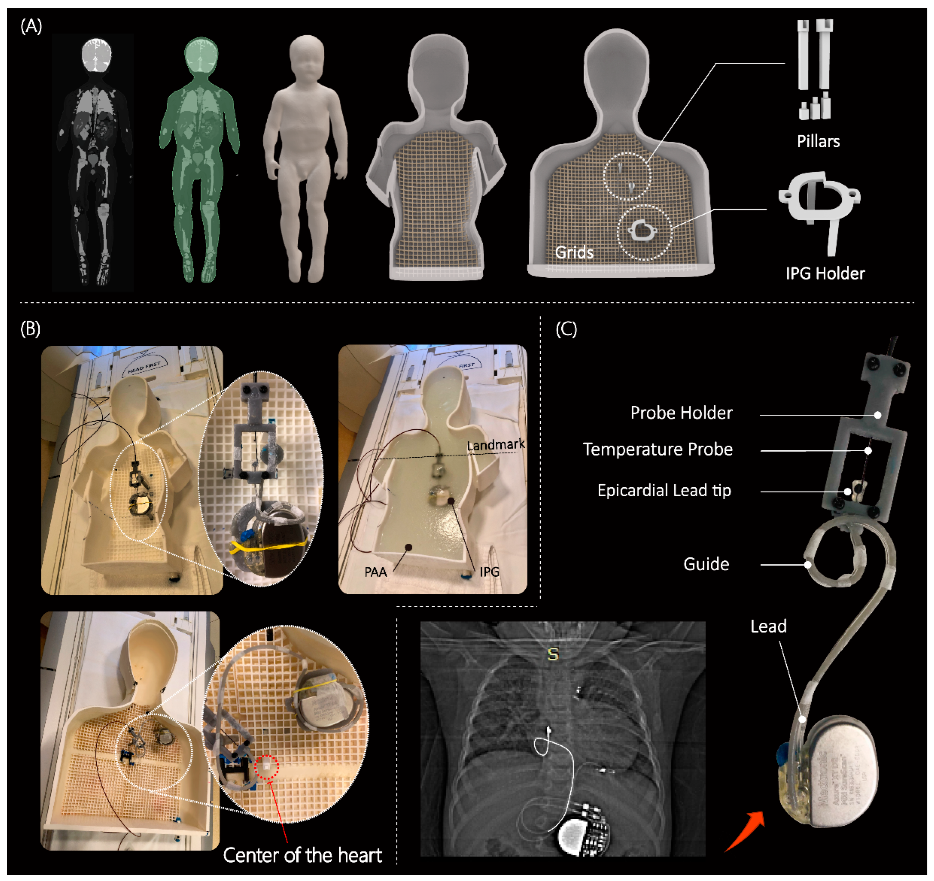
2.1. Phantom Design and Construction

Most studies that have assessed RF heating of conductive implants in the MRI environment have used a box-shaped phantom based on the ASTM standards [24]. However, a recent report highlighted a 10-fold discrepancy in the calculated specific absorption rate (SAR) in the ASTM box versus human body models [25]. This discrepancy was mainly attributed to the highly elliptical field polarization in the shallow-depth (~9 cm) ASTM phantom, which differs substantially from the field distribution in the human body. To address this issue, we developed custom-made human-shaped phantoms that mimicked the silhouette of an average-sized adult (length 65 cm, width 45 cm, depth 14 cm) and a twenty-nine-month-old child (length 53 cm, width 30 cm, depth 15 cm) (see Figure 2). The phantoms were filled with polyacrylamide (PAA) gel (22 L for the adult and 9 L for the pediatric phantom) with a conductivity of σ = 0.47 S/m and relative permittivity of ε r = 88, representing dielectric properties of a tissue-mimicking medium [7]. Care was taken to ensure that implanted leads and the IPG were submerged within the gel at a depth of 2–3 cm below the surface, mimicking the placement in patients.

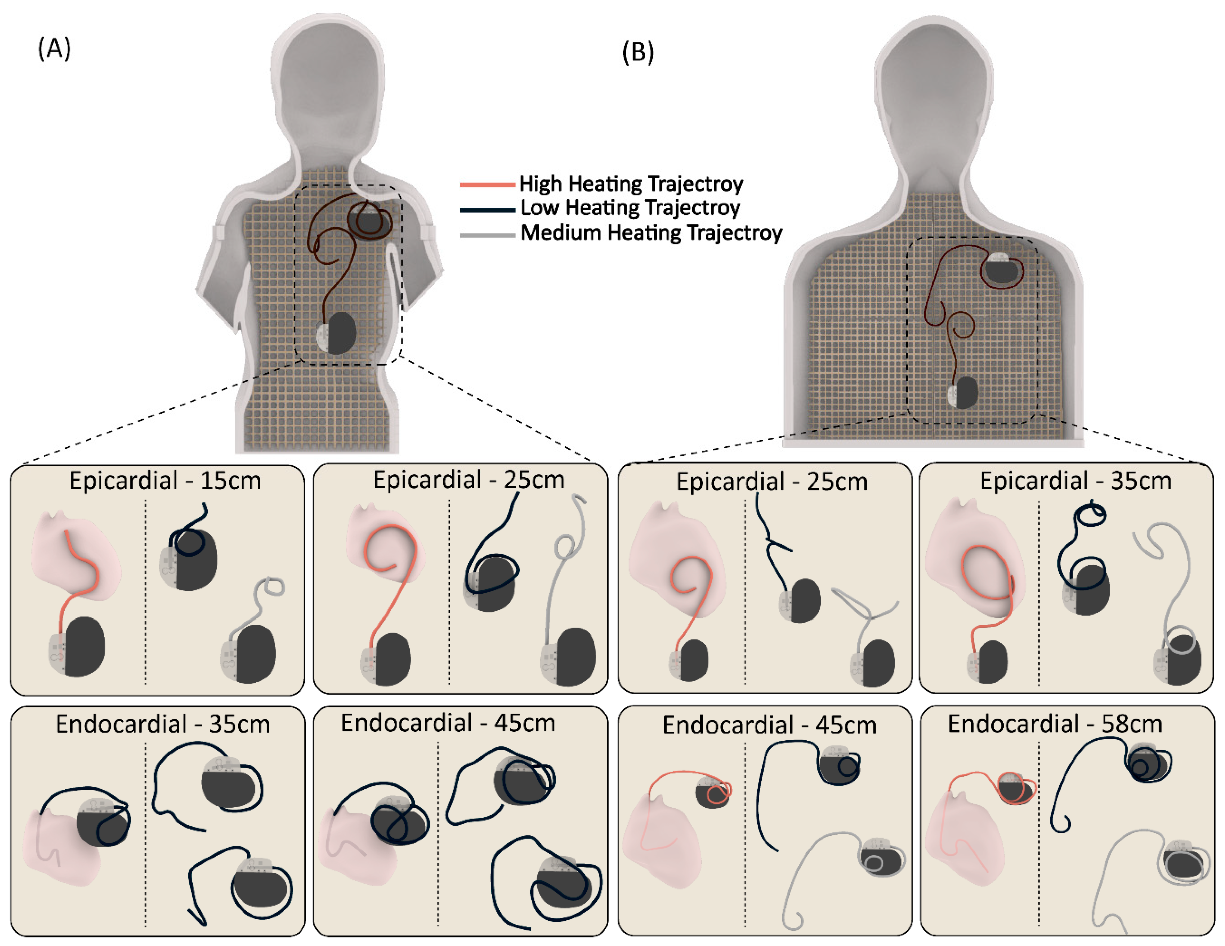
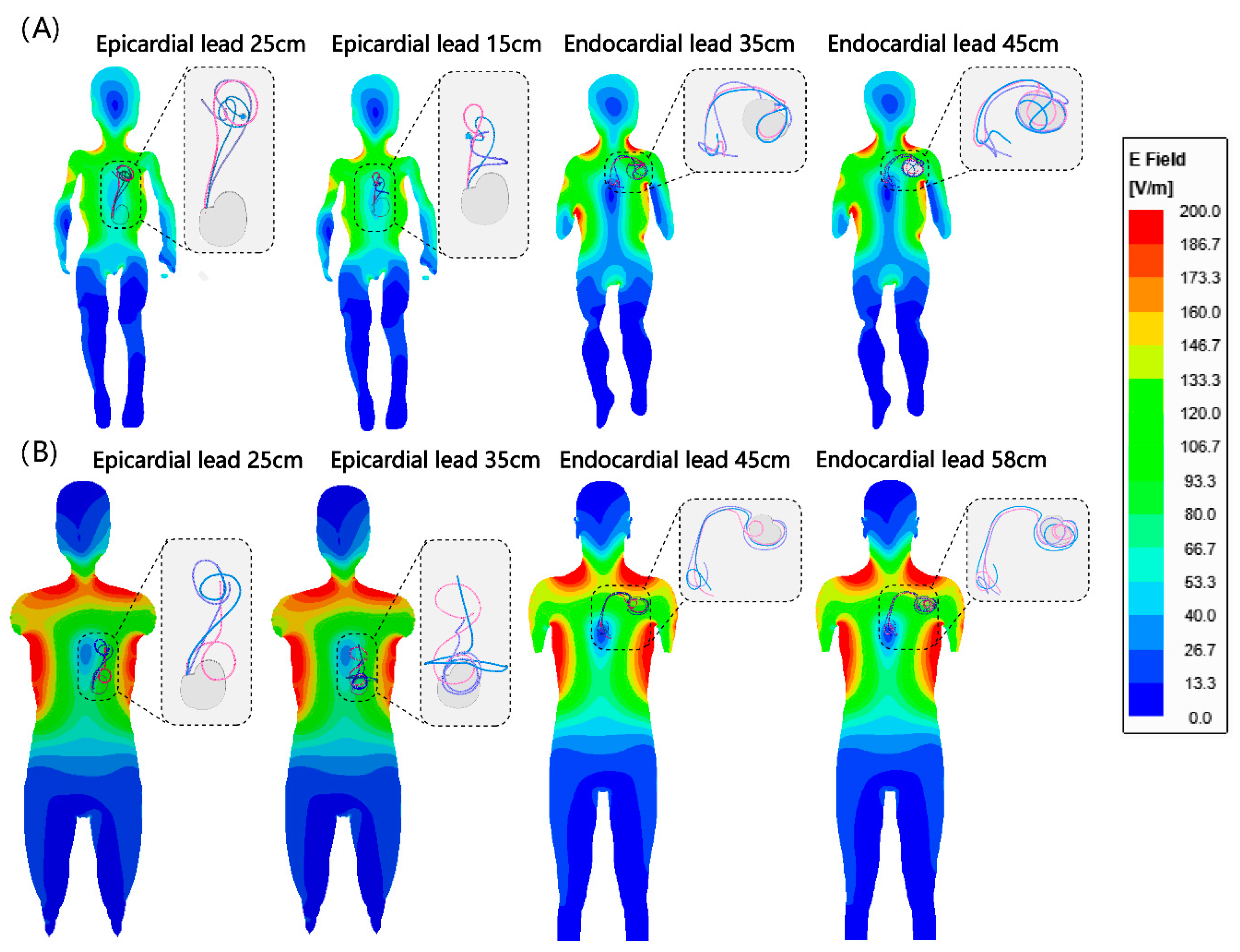
2.2. Device Configurations

The magnitude, polarization, and phase distribution of MRI incident electric field along the length of an implant determine the RF-induced currents on elongated implants [26,27,28,29,30,31]. Consequently, the position and trajectory of an implanted lead has a significant impact on the RF heating around its tip [20,31,32,33]. Thus, a reliable and robust RF safety assessment requires patient-derived device configurations. We retrospectively reviewed chest X-ray and computed tomography (CT) images of 200 adult and pediatric patients with epicardial and endocardial CIEDs to create representative device trajectories. The Institutional Review Boards of Northwestern University and Lurie Children’s Hospital approved the use of patient imaging data for modeling and safety assessment purposes. To ensure reproducibility, we designed and 3D printed trajectory guides to route the leads along patient-specific trajectories and keep them securely in place during the experiments, similar to previous studies [34,35] (see Figure 2C). We conducted experiments on epicardial systems using three of the most commonly used lead lengths (i.e., 15 cm, 25 cm, and 35 cm) (Medtronic CapSure® EPI 4965 (Minneapolice, MN, USA)). The leads were connected to a Medtronic Azure™ (Minneapolice, MN, USA) XT DR MRI SureScan pulse generator placed in the phantom’s abdomen. Experiments with the endocardial system used 35 cm, 45 cm, and 58 cm leads (CapSureFix Novus MRI™ SureScan™ bipolar 5076 (Minneapolice, MN, USA)) connected to the same pulse generator placed in the left infraclavicular region.
We performed 120 experiments in total, with 60 in each of the adult and child phantoms. We modeled clinically relevant trajectories using a combination of specific patient images, X-ray images available in the literature, and expert opinion, including input from author GW. We performed 60 experiments in the child phantom, with 15 cm and 25 cm epicardial leads and 35 cm and 45 cm endocardial leads routed along 15 patient-derived trajectories. Similarly, we conducted 60 experiments in the adult phantom, using 25 cm and 35 cm epicardial leads and 45 cm and 58 cm endocardial leads, each routed along 15 patient-derived trajectories. Figure 3 displays a few representative trajectories for each category. We can provide Computer-Aided Design (CAD) files for all 120 trajectories upon written request to the corresponding author. Both the epicardial pacing system and endocardial pacing system were powered off during the experiments.

2.3. Imaging Protocol

The temperature measurements were obtained using MR-compatible fiber optic probes (OSENSA, Vancouver, BC, Canada, resolution 0.01 °C) that were secured at the tip of the lead. A custom-made holder was 3D printed to ensure reliable thermal contact, allowing the temperature probe to remain in direct contact with the lead tip throughout the experiment. The RF exposure was conducted using a 1.5 T Siemens Aera scanner (Siemens Healthineers, Erlangen, Germany), with the phantoms positioned for cardiothoracic imaging. A high-SAR T1-weighted turbo spin echo (T1-TSE) sequence (TE = 7.3 ms, TR = 897 ms, B1+ = 5 µT, acquisition time = 280 s) was used. Although the acquisition time was shorter than typically used in RF heating experiments (i.e., ~5 min instead of 10 min), it was long enough to ensure that all temperature profiles reached a plateau, thereby ensuring the accuracy of our comparative temperature rise study.

2.4. Test-Retest Analysis

To assess the reliability of our measurements, we performed re-tests for 20% of the total number of cases (i.e., 24 experiments) and calculated the intraclass correlation coefficient (ICC). For each category, we selected trajectories that produced high, average, and low RF heating to maximize the heterogeneity of the re-test sample. ICC estimates and their 95% confidence intervals were calculated using RStudio (version 4.1.1) based on a single rating, absolute-agreement, two-way mixed-effects model [36].

2.5. Establishing Safe Exposure Limits Based on Worst-Case Scenarios

After conducting and validating comparative experiments, we identified device configurations that generated the highest heating for each category. Subsequently, we performed secondary experiments to determine the maximum RMS B1+ that generated less than 3 °C RF heating after 10 min of scanning. To achieve this, we implanted the worst-case RF heating device configurations into the phantoms and recorded the temperature at the lead’s tip during scanning with varying RMS B1+ values. To have complete control over the RF exposure characteristics, we disabled the gradient coils and transmitted a train of 1 ms rectangular RF pulses using the “rf_pulse” sequence from the Siemens Service Sequence directory. The flip angle was then adjusted to generate RMS B1+ values ranging from 2 µT to 5 µT. Pulse sequence parameters are summarized in Table 1 for each experiment. The maximum RMS B1+ allowed before the scanner stopped the operation was 5 µT, which corresponded to the scanner-reported SAR of 100%.

2.6. Statistical Analysis

A means comparison was implemented using t-tests to determine differences in heating between epicardial and endocardial leads in the adult and child phantoms. All statistical tests were run using RStudio (version 4.1.1) with a 95% confidence level.

3. Results

3.1. Reliability of Measurements

The test–retest experiments showed excellent reliability with an ICC of 0.95–0.99 at a 95% confidence interval. Supplementary Information Table S1 and Figure S1 provide the RF heating measurement values and corresponding device configurations.

3.2. RF Heating of CIEDs in the Pediatric Phantom

The mean ± SD RF heating in the pediatric phantom was 0.6 ± 0.4 °C for endocardial leads and 3.4 ± 3.0 °C for epicardial leads (pooled over both lead lengths in each case). The maximum RF heating recorded was ~12 °C for the 25 cm epicardial lead. For a 10-minute scan, this would be equivalent to a cumulative thermal dose of CEM43 °C = 640 min, high enough to cause necrosis in pig muscles [37].
The epicardial lead’s RF heating was significantly higher than that of endocardial leads in the pediatric phantom (p < 0.001). Within epicardial leads, the 25 cm lead generated higher RF heating than the 15 cm lead (4.4 ± 3.7 °C vs. 2.4 ± 1.5 °C, p < 0.05). Within endocardial leads, the 35 cm lead generated higher RF heating than the 45 cm lead (0.9 ± 0.4 °C vs. 0.4 ± 0.3 °C, p < 0.001).

3.3. RF Heating of CIEDs in the Adult Phantom

The mean ± SD RF heating in the adult phantom was 2.0 ± 1.8 °C for endocardial leads and 3.0 ± 3.2 °C for epicardial leads. A t-test comparison did not reveal a significant difference between RF heating of endocardial and epicardial leads (p = 0.16). The maximum RF heating recorded was ~12 °C for the 25 cm epicardial lead. Among epicardial leads, the 25 cm lead generated higher heating than the 35 cm lead (4.8 ± 3.5 °C vs. 1.2 ± 1.5 °C, p < 0.001). Among endocardial leads, the 45 cm lead generated higher heating than the 58 cm lead (3.2 ± 1.9 °C vs. 0.8 ± 0.7 °C, p < 0.001).

3.4. Adult vs. Pediatric Phantom

We found no significant difference between the RF heating of epicardial leads in the pediatric and adult phantoms (p = 0.65). However, endocardial leads in the pediatric phantom generated significantly less RF heating compared with endocardial leads in the adult phantom (0.6 ± 0.4 °C vs. 2.0 ± 1.8 °C, p < 0.001). This difference could be attributed to two factors. First, the incident MRI electric field tends to be lower in a child’s body compared with an adult body due to their smaller size and more central position within the RF coil. This can be observed in Figure 4. Figure 4 shows the simulated MRI incident E field (i.e., electric field in the body in the implant’s absence) in a 29-month-old body model compared with an adult body model, subject to RF exposure in a 64 MHz body coil. The input power of the coil was adjusted to generate a mean B1+ = 5 μT at the isocenter for both. CIED devices would be exposed to a higher incident electric field in the adult body compared with the child body (details of simulation setup and results are provided in the Supplementary Information Figure S2 and Table S2).
The second factor is attributable to differences in lead trajectories related to children’s anatomy. Because the IPG is much closer to the heart in pediatric patients compared with adults, there will be more excess lead length, which is usually looped around the IPG. The addition of these loops could have contributed to the lower RF heating similar to what is observed in neuromodulation devices [38,39]. This can be specifically appreciated comparing RF heating of the 45 cm endocardial leads in adult (3.2 ± 1.9 °C) vs. child (0.4 ± 0.3 °C) phantoms, where the difference in RF heating can be solely attributed to differences in position and trajectory of the lead (Figure 5). Individual temperature rise for each case is provided in the Supplementary Information Figure S3.

3.5. Effect of Lead’s Length

The maximum RF heating in both phantoms was observed for the 25 cm epicardial lead. The half wavelength of the radiofrequency field in the PAA ( ε r = 88) was ~ 24.5 cm, which explains the high heating as the length of the lead approached the resonance length. This phenomenon, commonly referred to as the resonance effect, has also been observed in other types of wire implants [40,41].

3.6. Estimation of Safe RMS B1+ Levels Based on Worst-Case Observations

Temperature rise distribution histograms are provided in the Supplementary Information Figure S4. For each case, the device configuration that generated the highest RF heating was used in subsequent experiments to estimate RMS B1+ values that constrained RF heating to <3 °C. Our data indicates that this approach was conservative, as >99% of cases in the general population would generate RF heating below this limit.
Figure 6 gives the RMS B1+ values and their corresponding RF heating for device configurations that generated highest heating in each category. For the pediatric phantom, both 35 cm and 45 cm endocardial leads generated RF heating well below 3 °C after 10 min of scanning at the maximum allowable RMS B1+ (i.e., 5µT) and, thus, are not shown in the graph. The maximum RMS B1+ that generated RF heating <3 °C was 2.5 µT for the 25 cm epicardial lead and 3.6 µT for the 15 cm epicardial lead.
For the adult phantom, the 58 cm endocardial lead generated RF heating well below 3 °C, so it is not shown in the graph. The maximum RMS B1+ that generated RF heating <3 °C was 2.3 µT and 3.2 µT for the 25 cm and 35 cm epicardial lead, respectively, and 3.3 µT for the 45 cm endocardial lead.

4. Discussion

4.1. Risk of MRI-Induced RF Heating in Patients with CIEDs

The severity of RF heating of CIEDs during MRI is influenced by two primary factors: the patient’s body size and the lead’s length/trajectory. The patient’s body size is a critical determinant because the distribution of the MRI electric field inside a sample is highly sensitive to its size and material composition. In children, the ratio of bone, fat, and muscle differs from that of adults, resulting in a substantially different electric field distribution at the CIED’s location. Therefore, safety assessments for MRI in children must be conducted using age-specific pediatric body models. The lead’s trajectory is the second determinant of RF heating and is correlated with the patient’s size, with smaller children receiving shorter leads. Even certain lead lengths that are common for both adults and children follow a different trajectory in children, requiring a different safety assessment. Our findings reveal that specific lead configurations in children generate significantly lower RF heating than the level deemed safe by the FDA for adults (e.g., 35 cm and 45 cm endocardial leads). However, some epicardial lead configurations generate excessive (e.g., 25 cm epicardial lead) RF heating which can cause myocardial lesions, underscoring the need for size- and lead-specific risk assessments.
There is a limited amount of available data concerning the MRI-induced RF heating of epicardial leads. In a recent in vitro study [12], temperature increase was measured at the tip of a commercially available bipolar epicardial lead (CapSureEpi 4968 with 35 cm, Medtronic) positioned in an ASTM phantom, with the lead location placed closer to the edge of the phantom. The trajectories included followed a straight path or coiling of varying lengths. However, in a realistic scenario, leads of pacemakers are usually looped at different locations to accommodate for the excess length. In this study, we specifically investigated the RF heating with leads along different realistic human-shape phantoms and aimed at obtaining a range of temperature changes to better represent the real-case scenario.

4.2. Rise of off-Label Scanning Is a Reality and Caution Is Warranted

So far, off-label MRI of CIED patients has been performed in several thousand adults and reported no significant side effects. The word “significant”, however, should be interpreted with caution. A recent study on adults with abandoned or functioning epicardial leads [42] found a transient elevation of pacing threshold in one patient, and an irreversible atrial pacing lead impedance elevation (>10,000 ohms) in another. While these may have been coincidental to the timing of the MRI, the retrospective nature of the study and the timing of the impedance rise make RF heating in the MRI scanner impossible to exclude. It is possible that RF heating in the MRI scanner led to a formation of low-conductivity scar tissue around the tip of the lead. Another study in pediatric and adult patients with epicardial or abandoned leads [14] reported a heat sensation in the left lateral chest at the location of an abandoned endocardial lead in one patient (36 years old)—which required the scan to be stopped—and a tingling sensation at the location of the epicardial lead in another. Even if these risks may be manageable in adults, there are additional factors that complicate accurate risk assessment in children. An infant or a 5 year old scanned under anesthesia cannot complain of a heating sensation to stop the MRI. The results could be an irreversible thermal injury of the heart tissue. Because myocardial scarring during early childhood can expand as the heart grows over time [43], such damages could cause long-term complications over the individual’s life span. While we did not find a systematic difference in RF heating of epicardial leads in pediatric vs. adult phantoms, marked heating elevations were present in clinically relevant scenarios. For example, our results show that MR-induced heating of epicardial leads reaches levels that are 267% higher in young children who mostly receive short epicardial leads (e.g., 25 cm) compared with adults who receive longer leads (e.g., 35 cm).

4.3. Perfusion in Accessing the Risk of MRI-Induced RF Heating

The wealth of national and international standards developed over the past two decades to ensure MRI safety unanimously recommend the use of perfusion-less phantoms to assess RF heating. The rationale behind this consensus is that neglecting cooling effects of perfusion which slightly overestimates RF heating adds a safety margin which is welcome when patient safety is at stake in a large population. The overestimation seems to be a reasonable trade off, considering that the epicardium, where the leads are affixed to, is excluded from circulation, and that in endocardium, which is cooled by circulation, the error due to exclusion of perfusion remains below 30% [13].

4.4. Limitations and Future Work

This work has several limitations. First, only a few epicardial and endocardial lead models were investigated. We are aware that other lead models exist in the market. Even within device models in our study, we limited our work to lead lengths that were most commonly used at our institution. For example, Medtronic 4965 epicardial leads also come in 50 cm length, and Medtronic 5076 endocardial leads also come in 52 cm, 65 cm and 85 cm lengths. Bipolar epicardial leads (e.g., Medtronic 4968 CapSure Epi (Minneapolice, MN, USA)) for biventricular or dual-chamber pacing were not investigated either. This was a compromise that allowed us to study each lead more thoroughly (i.e., more patient-derived trajectories) which we deemed to be crucial to infer conclusions on safety.
Second, this work only studied intact CIED devices; abandoned leads were not included. Abandoned leads are observed in a sizeable fraction of CIED patients for whom leads fail for technical reasons, infection, or blockage of the vein by clot. In such situations, the patient is referred for lead extraction and implantation of new leads [44] or lead abandonment and implantation of additional leads [45]. Extraction is not always successful in transvenous leads, and the risks of sternotomy and surgical lead extraction in patients with epicardial leads typically outweigh the benefits. This suggests that fractured epicardial leads are nearly always abandoned in place. Since MR-conditional labeling of a CIED only applies to the intact device with leads implanted in their original configuration, patients with abandoned leads are contraindicated for MRI. A recent study showed that capped abandoned leads induce tissue heating that is on average 3.5 times higher than what is generated by a complete CIED system [46]. Thus, the results of this study should not be generalized to cases of abandoned leads.

Supplementary Materials

The following supporting information can be downloaded at: https://www.mdpi.com/article/10.3390/diagnostics13172847/s1, Figure S1: Device configurations used in test-retest experiments; Table S1: Temperature rises for test–retest experiments; Figure S2: Simulation setup; Table S2: Mesh characteristics for the simulations of pediatric and adult body models; Figure S3: Temperature rise in the gel round tips of the leads with 120 distinct trajectories in pediatric and adult phantoms; Figure S4: Histograms of scaled temperature rises.

Author Contributions

Conceptualization, F.J., G.W., A.P., D.K. and L.G.; methodology, F.J., B.B. and L.G.; validation, F.J. and L.G.; formal analysis, F.J., K.R.H. and C.L.; investigation, F.J., K.R.H., P.S. and B.B.; resources, L.G.; data curation, F.J.; writing—original draft preparation, F.J. and K.R.H.; writing—review and editing, L.G., G.W. and D.K.; visualization, F.J.; supervision, L.G.; project administration, L.G.; funding acquisition, L.G. All authors have read and agreed to the published version of the manuscript.

Funding

This research was supported by the National Institute of Health (NIH) under grant number R01EB034377, the contributions from the Brett Boyer Foundation, and through in-kind donation of medical devices provided by Medtronic Inc.

Institutional Review Board Statement

The study was conducted in accordance with the Declaration of Helsinki and approved by the Institutional Review Board of Northwestern University (STU00206859, approved on 9 August 2022) and Ann and Lurie Children’s Hospital (IRB# 2021-4762, approved on 21 July 2021).

Informed Consent Statement

Patient consent was waived due to the retrospective nature of the study.

Data Availability Statement

Not applicable.

Acknowledgments

Authors would like to thank Giorgio Bonmassar for providing pediatric body models.

Conflicts of Interest

The authors declare no conflict of interest.

References

  1. Wood, M.A.; Ellenbogen, K.A. Cardiac Pacemakers From the Patient’s Perspective. Circulation 2002, 105, 2136–2138. [Google Scholar] [CrossRef] [PubMed]
  2. McLeod, K.A. Cardiac pacing in infants and children. Heart 2010, 96, 1502–1508. [Google Scholar] [CrossRef]
  3. Sachweh, J.S.; Vazquez-Jimenez, J.F.; Schondube, F.A.; Daebritz, S.H.; Dorge, H.; Muhler, E.G.; Messmer, B.J. Twenty years experience with pediatric pacing: Epicardial and transvenous stimulation. Eur. J. Cardiothorac. Surg. 2000, 17, 455–461. [Google Scholar] [CrossRef]
  4. Kalin, R.; Stanton, M.S. Current clinical issues for MRI scanning of pacemaker and defibrillator patients. Pacing Clin. Electrophysiol. PACE 2005, 28, 326–328. [Google Scholar] [CrossRef]
  5. Mascioli, G.; Lucca, E.; Michelotti, F.; Tarantino, L.; Giofré, F.; Finamora, I. Need for MRI scans in a real-world CIED population over long-term follow-up: Data from a large single-centre experience. PLoS ONE 2020, 15, e0244672. [Google Scholar] [CrossRef]
  6. Taruya, A.; Tanaka, A.; Nishiguchi, T.; Iwaguro, T.; Ueno, S.; Okumoto, Y.; Kubo, T.; Akagi, H.; Akasaka, T. Necessity of magnetic resonance imaging examinations after permanent pacemaker implantation. Int. J. Cardiol. 2015, 184, 497–498. [Google Scholar] [CrossRef] [PubMed]
  7. ISO TS 10974; Assessment of the Safety of Magnetic Resonance Imaging for Patients with an Active Implantable Medical Device. International Organization for Standardization: Geneva, Switzerland, 2018.
  8. Nazarian, S.; Cantillon, D.J.; Woodard, P.K.; Mela, T.; Cline, A.M.; Strickberger, A.S. MRI Safety for Patients Implanted with the MRI Ready ICD System. JACC Clin. Electrophysiol. 2019, 5, 935–943. [Google Scholar] [CrossRef]
  9. Russo, R.J.; Costa, H.S.; Silva, P.D.; Anderson, J.L.; Arshad, A.; Biederman, R.W.W.; Boyle, N.G.; Frabizzio, J.V.; Birgersdotter-Green, U.; Higgins, S.L.; et al. Assessing the Risks Associated with MRI in Patients with a Pacemaker or Defibrillator. N. Engl. J. Med. 2017, 376, 755–764. [Google Scholar] [CrossRef] [PubMed]
  10. Schaller, R.D.; Brunker, T.; Riley, M.P.; Marchlinski, F.E.; Nazarian, S.; Litt, H. Magnetic Resonance Imaging in Patients with Cardiac Implantable Electronic Devices with Abandoned Leads. JAMA Cardiol. 2021, 6, 549–556. [Google Scholar] [CrossRef]
  11. Gupta, S.K.; Ya’qoub, L.; Wimmer, A.P.; Fisher, S.; Saeed, I.M. Safety and Clinical Impact of MRI in Patients with Non–MRI-conditional Cardiac Devices. Radiol. Cardiothorac. Imaging 2020, 2, e200086. [Google Scholar] [CrossRef]
  12. Balmer, C.; Gass, M.; Dave, H.; Duru, F.; Luechinger, R. Magnetic resonance imaging of patients with epicardial leads: In vitro evaluation of temperature changes at the lead tip. J. Interv. Card. Electrophysiol. Int. J. Arrhythm. Pacing 2019, 56, 321–326. [Google Scholar] [CrossRef]
  13. Indik, J.H.; Gimbel, J.R.; Abe, H.; Alkmim-Teixeira, R.; Birgersdotter-Green, U.; Clarke, G.D.; Dickfeld, T.L.; Froelich, J.W.; Grant, J.; Hayes, D.L.; et al. 2017 HRS expert consensus statement on magnetic resonance imaging and radiation exposure in patients with cardiovascular implantable electronic devices. Heart Rhythm 2017, 14, e97–e153. [Google Scholar] [CrossRef] [PubMed]
  14. Gakenheimer-Smith, L.; Etheridge, S.P.; Niu, M.C.; Ou, Z.; Presson, A.P.; Whitaker, P.; Su, J.; Puchalski, M.D.; Asaki, S.Y.; Pilcher, T. MRI in pediatric and congenital heart disease patients with CIEDs and epicardial or abandoned leads. Pacing Clin. Electrophysiol. 2020, 43, 797–804. [Google Scholar] [CrossRef] [PubMed]
  15. Bireley, M.; Kovach, J.R.; Morton, C.; Cava, J.R.; Pan, A.Y.; Nugent, M.; Samyn, M.M. Cardiac magnetic resonance imaging (MRI) in children is safe with most pacemaker systems, including those with epicardial leads. Pediatr. Cardiol. 2020, 41, 801–808. [Google Scholar] [CrossRef]
  16. Shah, M.J.; Silka, M.J.; Silva, J.N.A.; Balaji, S.; Beach, C.M.; Benjamin, M.N.; Berul, C.I.; Cannon, B.; Cecchin, F.; Cohen, M.I.; et al. 2021 PACES expert consensus statement on the indications and management of cardiovascular implantable electronic devices in pediatric patients. Cardiol. Young 2021, 31, 1738–1769. [Google Scholar] [CrossRef] [PubMed]
  17. Mattei, E.; Triventi, M.; Calcagnini, G.; Censi, F.; Kainz, W.; Mendoza, G.; Bassen, H.I.; Bartolini, P. Complexity of MRI induced heating on metallic leads: Experimental measurements of 374 configurations. Biomed. Eng. Online 2008, 7, 11. [Google Scholar] [CrossRef]
  18. Bhusal, B.; Nguyen, B.T.; Sanpitak, P.P.; Vu, J.; Elahi, B.; Rosenow, J.; Nolt, M.J.; Lopez-Rosado, R.; Pilitsis, J.; DiMarzio, M.; et al. Effect of Device Configuration and Patient’s Body Composition on the RF Heating and Nonsusceptibility Artifact of Deep Brain Stimulation Implants During MRI at 1.5 T and 3T. J. Magn. Reson. Imaging 2021, 53, 599–610. [Google Scholar] [CrossRef]
  19. Vu, J.; Bhusal, B.; Rosenow, J.; Pilitsis, J.; Golestanirad, L. Modifying surgical implantation of deep brain stimulation leads significantly reduces RF-induced heating during 3 T MRI. In Proceedings of the 2021 43rd Annual International Conference of the IEEE Engineering in Medicine & Biology Society (EMBC), Online, 1–5 November 2021; pp. 4978–4981. [Google Scholar]
  20. Nordbeck, P.; Weiss, I.; Ehses, P.; Ritter, O.; Warmuth, M.; Fidler, F.; Herold, V.; Jakob, P.M.; Ladd, M.E.; Quick, H.H. Measuring RF-induced currents inside implants: Impact of device configuration on MRI safety of cardiac pacemaker leads. Magn. Reson. Med. 2009, 61, 570–578. [Google Scholar] [CrossRef]
  21. McElcheran, C.; Golestanirad, L.; Iacono, M.; Wei, P.-S.; Yang, B.; Anderson, K.; Bonmassar, G.; Graham, S. Numerical simulations of realistic lead trajectories and an experimental verification support the efficacy of parallel radiofrequency transmission to reduce heating of deep brain stimulation implants during MRI. Sci. Rep. 2019, 9, 2124. [Google Scholar] [CrossRef]
  22. Van Den Bergen, B.; van den Berg, C.; Kroeze, H.; Bartels, L.; Lagendijk, J. The effect of body size and shape on RF safety and B1 field homogeneity at 3T. Proc. Intl. Soc. Mag. Reson. Med. 2006, 14, 2040. [Google Scholar]
  23. Sanpitak, P.; Bhusal, B.; Nguyen, B.T.; Vu, J.; Chow, K.; Bi, X.; Golestanirad, L. On the accuracy of Tier 4 simulations to predict RF heating of wire implants during magnetic resonance imaging at 1.5 T. In Proceedings of the 2021 43rd Annual International Conference of the IEEE Engineering in Medicine & Biology Society (EMBC), Online, 1–5 November 2021; pp. 4982–4985. [Google Scholar]
  24. ASTM F2182-11a; Standard Test Method for Measurement of Radio Frequency Induced Heating on or Near Passive Implants during Magnetic Resonance Imaging. ASTM International: West Conshohocken, PA, USA, 2011.
  25. Fujimoto, K.; Angelone, L.M.; Lucano, E.; Rajan, S.S.; Iacono, M.I. Radio-Frequency Safety Assessment of Stents in Blood Vessels During Magnetic Resonance Imaging. Front. Physiol. 2018, 9, 1439. [Google Scholar] [CrossRef] [PubMed]
  26. McElcheran, C.E.; Yang, B.; Anderson, K.J.; Golestanirad, L.; Graham, S.J. Parallel radiofrequency transmission at 3 tesla to improve safety in bilateral implanted wires in a heterogeneous model. Magn. Reson. Med. 2017, 78, 2406–2415. [Google Scholar] [CrossRef] [PubMed]
  27. Golestanirad, L.; Keil, B.; Angelone, L.M.; Bonmassar, G.; Mareyam, A.; Wald, L.L. Feasibility of using linearly polarized rotating birdcage transmitters and close-fitting receive arrays in MRI to reduce SAR in the vicinity of deep brain simulation implants. Magn. Reson. Med. 2017, 77, 1701–1712. [Google Scholar] [CrossRef] [PubMed]
  28. Yeung, C.J.; Susil, R.C.; Atalar, E. RF heating due to conductive wires during MRI depends on the phase distribution of the transmit field. Magn. Reson. Med. Off. J. Int. Soc. Magn. Reson. Med. 2002, 48, 1096–1098. [Google Scholar] [CrossRef]
  29. Park, S.M.; Kamondetdacha, R.; Nyenhuis, J.A. Calculation of MRI-induced heating of an implanted medical lead wire with an electric field transfer function. J. Magn. Reson. Imaging: Off. J. Int. Soc. Magn. Reson. Med. 2007, 26, 1278–1285. [Google Scholar] [CrossRef]
  30. Kazemivalipour, E.; Bhusal, B.; Vu, J.; Lin, S.; Nguyen, B.T.; Kirsch, J.; Nowac, E.; Pilitsis, J.; Rosenow, J.; Atalar, E.; et al. Vertical open-bore MRI scanners generate significantly less radiofrequency heating around implanted leads: A study of deep brain stimulation implants in 1.2 T OASIS scanners versus 1.5 T horizontal systems. Magn. Reson. Med. 2021, 86, 1560–1572. [Google Scholar] [CrossRef]
  31. Golestanirad, L.; Angelone, L.M.; Iacono, M.I.; Katnani, H.; Wald, L.L.; Bonmassar, G. Local SAR near deep brain stimulation (DBS) electrodes at 64 and 127 MH z: A simulation study of the effect of extracranial loops. Magn. Reson. Med. 2017, 78, 1558–1565. [Google Scholar] [CrossRef]
  32. Nguyen, B.T.; Bhusal, B.; Rahsepar, A.A.; Fawcett, K.; Lin, S.; Marks, D.S.; Passman, R.; Nieto, D.; Niemzcura, R.; Golestanirad, L. Safety of MRI in patients with retained cardiac leads. Magn. Reson. Med. 2022, 87, 2464–2480. [Google Scholar] [CrossRef]
  33. Vu, J.; Nguyen, B.T.; Bhusal, B.; Baraboo, J.; Rosenow, J.; Bagci, U.; Bright, M.G.; Golestanirad, L. Machine Learning-Based Prediction of MRI-Induced Power Absorption in the Tissue in Patients With Simplified Deep Brain Stimulation Lead Models. IEEE Trans. Electromagn. Compat. 2021, 63, 1757–1766. [Google Scholar] [CrossRef]
  34. Golestanirad, L.; Kazemivalipour, E.; Keil, B.; Downs, S.; Kirsch, J.; Elahi, B.; Pilitsis, J.; Wald, L.L. Reconfigurable MRI coil technology can substantially reduce RF heating of deep brain stimulation implants: First in-vitro study of RF heating reduction in bilateral DBS leads at 1.5 T. PLoS ONE 2019, 14, e0220043. [Google Scholar] [CrossRef]
  35. Bhusal, B.; Stockmann, J.; Guerin, B.; Mareyam, A.; Kirsch, J.; Wald, L.L.; Nolt, M.J.; Rosenow, J.; Lopez-Rosado, R.; Elahi, B.; et al. Safety and image quality at 7T MRI for deep brain stimulation systems: Ex vivo study with lead-only and full-systems. PLoS ONE 2021, 16, e0257077. [Google Scholar] [CrossRef]
  36. Koo, T.K.; Li, M.Y. A Guideline of Selecting and Reporting Intraclass Correlation Coefficients for Reliability Research. J. Chiropract. Med. 2016, 15, 155–163. [Google Scholar] [CrossRef] [PubMed]
  37. van Rhoon, G.C.; Samaras, T.; Yarmolenko, P.S.; Dewhirst, M.W.; Neufeld, E.; Kuster, N. CEM43°C thermal dose thresholds: A potential guide for magnetic resonance radiofrequency exposure levels? Eur. Radiol. 2013, 23, 2215–2227. [Google Scholar] [CrossRef] [PubMed]
  38. Golestanirad, L.; Kirsch, J.; Bonmassar, G.; Downs, S.; Elahi, B.; Martin, A.; Iacono, M.-I.; Angelone, L.M.; Keil, B.; Wald, L.L. RF-induced heating in tissue near bilateral DBS implants during MRI at 1.5 T and 3T: The role of surgical lead management. Neuroimage 2019, 184, 566–576. [Google Scholar] [CrossRef] [PubMed]
  39. Baker, K.B.; Tkach, J.; Hall, J.D.; Nyenhuis, J.A.; Shellock, F.G.; Rezai, A.R. Reduction of magnetic resonance imaging-related heating in deep brain stimulation leads using a lead management device. Oper. Neurosurg. 2005, 57, ONS-392–ONS-397. [Google Scholar] [CrossRef]
  40. Bhusal, B.; Bhattacharyya, P.; Baig, T.; Jones, S.; Martens, M. Measurements and simulation of RF heating of implanted stereo-electroencephalography electrodes during MR scans. Magn. Reson. Med. 2018, 80, 1676–1685. [Google Scholar] [CrossRef]
  41. Yeung, C.J.; Susil, R.C.; Atalar, E. RF safety of wires in interventional MRI: Using a safety index. Magn. Reson. Med. Off. J. Int. Soc. Magn. Reson. Med. 2002, 47, 187–193. [Google Scholar] [CrossRef]
  42. Vuorinen, A.-M.; Paakkanen, R.; Karvonen, J.; Sinisalo, J.; Holmström, M.; Kivistö, S.; Peltonen, J.I.; Kaasalainen, T. Magnetic resonance imaging safety in patients with abandoned or functioning epicardial pacing leads. Eur. Radiol. 2022, 32, 3830–3838. [Google Scholar] [CrossRef]
  43. Saul, J.P.; Hulse, J.E.; Papagiannis, J.; Van Praagh, R.; Walsh, E.P. Late enlargement of radiofrequency lesions in infant lambs. Implications for ablation procedures in small children. Circulation 1994, 90, 492–499. [Google Scholar] [CrossRef]
  44. Friedman, R.A.; Zandt, H.; Collins, E.; LeGras, M.; Perry, J. Lead extraction in young patients with and without congenital heart disease using the subclavian approach. Pacing Clin. Electrophysiol. 1996, 19, 778–783. [Google Scholar] [CrossRef]
  45. Silvetti, M.S.; Drago, F. Upgrading of VVIR pacemakers with nonfunctional endocardial ventricular leads to VDD pacemakers in adolescents. Pacing Clin. Electrophysiol. 2006, 29, 691–696. [Google Scholar] [CrossRef] [PubMed]
  46. Wang, Y.; Guo, R.; Hu, W.; Zheng, J.; Wang, Q.; Jiang, J.; Kurpad, K.K.; Kaula, N.; Long, S.; Chen, J. Magnetic resonance conditionality of abandoned leads from active implantable medical devices at 1.5 T. Magn. Reson. Med. 2022, 87, 394–408. [Google Scholar] [CrossRef] [PubMed]
Figure 1. (A) Typical trajectory of an endocardial lead. Leads pass through the subclavian vein creating a stereotypical pathway in nearly all patients. In contrast, epicardial devices can have highly varied lead trajectories (B,C).
Diagnostics 13 02847 g001
Figure 2. (A) 3D models of human-shaped pediatric and adult phantoms created from MRI of a 29-month-old child and representative images of an average-sized adult; the phantoms include grids, pillars, and different heights of pillar extensions to adjust the positioning of the CIEDs. (B) Assembled phantoms with implanted CIED and temperature measuring setup; cardiothoracic imaging landmark was used during MR scans. (C) An example of a patient-derived trajectory of an implanted lead obtained from X-ray image; close view of contact between the temperature probe and epicardial lead tip. The pediatric and adult phantom were 3D printed using Rigid 4000 resin (Formlabs, Somerville, MA, USA) and ABS Plastic, respectively. Pillars, holders, and extensions were made of Tough 1500 resin (Formlabs, Somerville, MA, USA).
Diagnostics 13 02847 g002
Figure 3. Representative patient-derived trajectories for each CIED category (24 trajectories in total) in (A) pediatric and (B) adult phantoms.
Diagnostics 13 02847 g003
Figure 4. Simulated incident E field in (A) homogeneous child and (B) adult body models. Note that the incident field is the electric field of the MRI scanner in the absence of any implant. Trajectories of endocardial and epicardial devices are overlaid on the field maps for comparison. Details of simulation setting are provided in the Supplementary Information Figure S2 and Table S2.
Diagnostics 13 02847 g004
Figure 5. Temperature rise in the gel around the tips of the leads with 120 distinct trajectories implanted in pediatric and adult phantoms.
Diagnostics 13 02847 g005
Figure 6. RMS B1+ values and their corresponding RF heating for device configurations that generated highest heating in each category for (A) child and (B) adult phantom. Black dots: RMS B1+ value that generates the temperature rise below 3 °C.
Diagnostics 13 02847 g006
Table 1. RF pulse parameters to establish the safe exposure limits.
FrequencyDurationTR
64 MHz603 s24.03 ms
Patient weight enteredPatient weight entered
68.0 kg13.6 kg
Flip Angle (°)B1 + rms [µT]Flip Angle (°)B1 + rms [µT]
3604.803604.82
3304.403304.41
3004.002953.95
2703.602853.81
2403.202783.72
2102.802703.61
1802.402653.55
1702.272453.28
1502.002353.15
2253.01
2052.74
1952.61
1852.48
1752.34
Disclaimer/Publisher’s Note: The statements, opinions and data contained in all publications are solely those of the individual author(s) and contributor(s) and not of MDPI and/or the editor(s). MDPI and/or the editor(s) disclaim responsibility for any injury to people or property resulting from any ideas, methods, instructions or products referred to in the content.

