1. Introduction
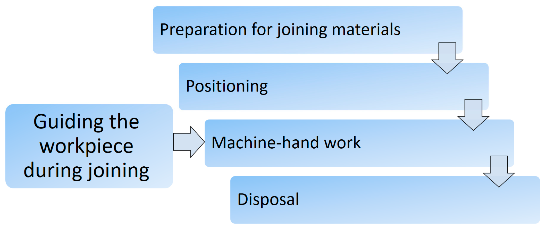
In order to organise production systems in many technologies, it is necessary to know the optimal working methods of each technological process and the corresponding time norm already in the product design phase. Industrial engineering methods for determining the time of hand sub-operations included in the technological operation (preparation of materials for machine operation and positioning, alignment, sub-operations performed during the interruption of machine operation, laying off) are used in the system of predetermined normal times or synthetic times. The most commonly used is the Methods Time Measurement (MTM). Sets of basic motions have been developed in the MTM system. Each technological operation in production consists of several sequences in a row, and usually it is about the initial hand preparation of materials for processing, positioning of materials in the working zone of the machine, simultaneous man-machine work and final laying off of materials,
Figure 1.
The greatest difficulties in using the system of predetermined normal times arise in determining the simultaneous times at which the machine (making changes to the material) and the worker (guiding the workpiece) work together, so-called machine-hand times.
In the Industrial Engineering Handbook, Maynard insisted on finding methods and expressions for determining machine-hand sewing times. This is important for organizing the process of clothing production on a scientific basis [
1]. Machine-hand operating time can be determined not only on the basis of determining the duration of the worker’s movement while guiding the workpiece, but the characteristics of machine operation must also be taken into account. In addition to movements of parts of the body and worker’s ability to react, other, usually technical parameters of machines, technological parameters relating to technological operations and technological conditions, ergonomics of workplace design and working methods, including psychophysiological and cybernetic characteristics of workers, have a significant impact. Unfortunately, due to the aforementioned wide range of influencing parameters and very specific technical machine designs, synthetic time systems still do not have elaborated methods for determining accurate machine-hand times for each individual machines or groups of similar machines [
2].
Previous methods of determining machine-hand times of technological operations have mainly been based only on the performance characteristics of the machine and can be used in a relatively small number of cases of determining machine-hand times. Usually, this involves the nominal working speed of the machine, the displacement of the machine element and other simple technical characteristics, but nowadays this is not enough, especially if it is a modern high-tech complex machine with a large number of influencing parameters.
For the purposes of garment technology, W. Möller developed and published a method for determining machine-hand sewing times of garments by successfully taking into account and combining the technical characteristics of sewing machines and the ergonomic reaction characteristics of workers. His method was successfully applied in the production of clothing and later in other production processes (upholstery of furniture, production of car seats, aeroplanes and other vehicles, production of household and medical textiles, bags for laptops and mobile phones, awnings, sails, tarpaulins and many other technical creations made by joining cut shapes from textiles and other materials). In order to determine more precise time norms of technological operations, W. Möller [
2] considered and determined the influence of some technical and technological parameters, including the specific density of machine sewing stitches, the seam length, three groups of seams with characteristic radii of curvature of the seam line, and the maximum sewing machine sewing speed. Most importantly, he introduced coefficients of increasing the time required to perform machine-hand operations and reducing the sewing speed, based on the ergonomic principles of human reactions when sewing curved seams.
A very intensive development of engineering and technology, including garment engineering with techniques for making up technical textiles, has led to the application of completely new high-tech joining processes such as ultrasonic welding, joining by means of thermal convection and heat conduction, high-frequency welding and IR laser welding, in addition to the long-established technique of joining garments by sewing. Among the new high-tech joining processes, the ultrasonic welding technique is often used because of a number of good properties such as water and air tightness of the welds, welding speed and excellent weld strength.
Ultrasonic welding is one of the most popular welding techniques used in all major industries. It is fast, economical, easily automated, and well suited for mass production [
3].
The use of sewing machines (needles make holes) is not applicable for waterproof and airtight protective clothing(e.g., clothing for special services—soldiers, policemen, fire fighters—when they intervene in the event of accidents in cold conditions, in traffic accidents, natural disasters, etc., and by security guards, rangers, paramedics, etc., who spend most of their time in cold environments and open spaces in windy and cold seasons), as well as to join parts of intelligent and smart clothing and other technical products made of polymer materials (awnings, tents, tarpaulins, geotextiles, automotive). Furthermore, ultrasonic welding machines with a rotary sonotrode are used to make military uniforms (U.S. military, NATO, etc.) and police uniforms for cold environments. Moreover, ultrasonic welding machines with a rotary sonotrode are used for medical face masks and surgical clothing. Body protection provided by medical gowns and aprons or chemical (biological) protective clothing are another form of protective equipment that is recommended to use by healthcare workers involved in the direct care of COVID-19 patients [
4]. Protective clothing made of airtight materials are joined with ultrasonic welding machines with a rotary sonotrode and thus air does not enter through the joints, as well as the viruses.
It is characterised by hand guiding the workpiece during joining, so that the percentage of machine hand work is also present in the technological operations of ultrasonic welding. The time of performing machine-hand work cannot be predetermined, as no adequate method has yet been developed due to the relatively short period of use of this technique and a number of new technical and technological parameters. As the ultrasonic welding technology is increasingly replacing conventional sewing technology, the need to determine the welding time using this technique is becoming increasingly important.
Precisely for these reasons, in the present work, some initial elements of W. Möller’s innovative approach to the determination of machine hand times in technological sewing operations were used; the development of a completely new model and mathematical expressions for determining machine hand times for the ultrasonic welding technique with a rotary sonotrode are presented, thereby taking into account a larger number of new specific technical, technological and ergonomic parameters. On the basis of the developed model, machine-hand or technological times and recommended ultrasonic welding speeds for different lengths of ultrasonic welds, different radii of their curvature and for different welding accuracies were determined. Besides, a new model for predetermining machine hand times was tested on the existing machine with a rotary sonotrode for ultrasonic welding of polymer materials by comparing the calculated and actual welding times [
2].
2. Some Basic Principles of the Reaction Model according to Möller during Sewing
Technological operations for joining garments are carried out on machines which are characterised by machine-hand work due to the physical and mechanical characteristics of the workpiece, the need for careful handling and a variety of shapes and dimensions. In such a working system, the machine and the worker work together and at the same time as they perform a technological sub-operation, on which, depending on the degree of training of the worker, the radius of curvature of the seam, the necessary welding accuracy and the specific stitch density of the seam and the maximum sewing speed of the sewing machine, will depend on the time required to perform the machine-hand welding sub-operation. During the welding process, the control system in the worker’s brain adapts the welding speed (transport of the workpiece), i.e., the actual stitching speed, according to the psychophysical abilities of the worker and the degree of his training, by moving the foot according to sensory and motor reactions to track and correct the seam line trajectory. Heckner [
5], Krovatchek and Nestler [
6] began to deal with this problem area.
Krowatschek and Ludemann [
7] found that the interaction between man, machine, workpiece and the environment characterises the technological processes of sewing clothing. Together they form a complex action system, which includes guiding the fabric along the seam contour during sewing, adjusting the fabric edges and length compensation of the fabric as a fundamentally coordinated reaction of visual factors and manual action when stopping the fabric and the machine at a certain distance from the end of the seam, deactivating one of the needles and activating auxiliary devices, etc. These sub-operations require a high level of mental concentration and coordination of the worker’s movements.
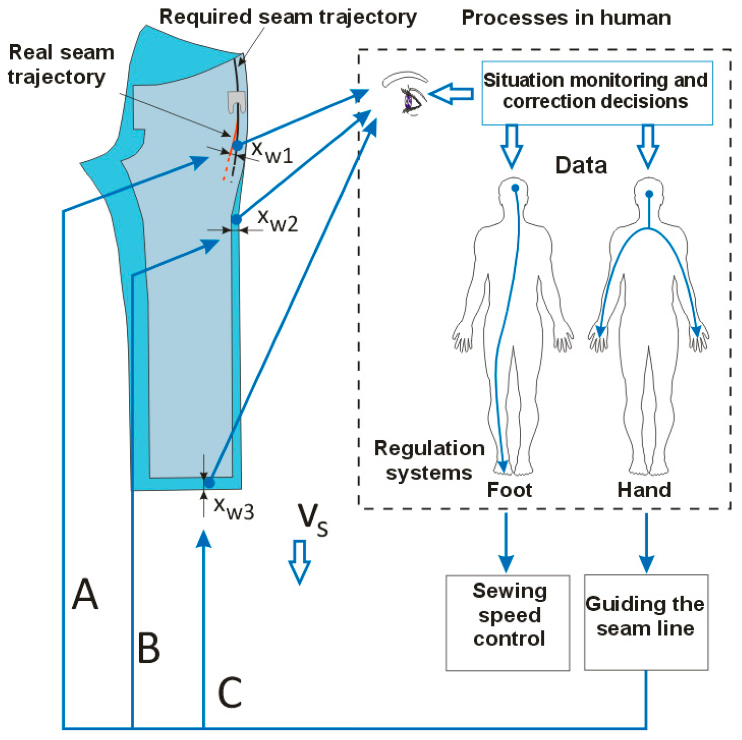
According to Krowatschek and Ludemann the man-machine-workpiece system during the technological sub-operation of machine-hand sewing when guiding a workpiece, there are three basic and independent feedback control circuits [
7]:
A—Control circuit for precise guiding the seam line (approximately equal distance of the seam from the edge of the workpiece);
B—Control circuit for exact matching of the position of the edges of the layers to be joined; and
C—Control circuit of the exact end of the weld at the end of each layer to be joined.
Figure 2 shows the control circuits of the man-machine-workpiece system in machine-hand sewing, where two layers of the workpiece are joined (positions 1 and 2).
Designation A indicates the deviation from the required and made seam lines, designation B indicates the deviation of the position of the edges of the layers and designation C indicates the deviation of the ends of the material layers, including permissible tolerances xw1, xw2, xw3.
The task of successful workpiece guiding in machine-hand sewing is that the difference in the deviation of the values of individual variables of seam quality lies within the permissible tolerance limits.
The task of successful workpiece guiding in machine hand sewing is to ensure that the difference in the deviation of the values of individual variables of the seam quality lies within the permissible tolerance limits.
The course of the technological sub-operation of machine hand sewing is highly dynamic, and due to the relatively high speed of workpiece transport by the machine feed and the required accuracy of workpiece guiding, the physical function of the latent reaction time is also important. Latent reaction time is the total time that elapses between the occurrence of the stimulus of a particular sensation and the start of the corresponding corrective movement.
Kumbhar et al. [
8] state that human reaction times vary, e.g., from 0.2 to 10 s. A reaction time of 0.2 s has been accepted in the clothing industry because it is cited by several independent authors, notably K. H. E. Kroemer [
9], H. Shmitke [
10], and H. J. Bullinger [
11].
It was recognised at a very early stage that, in addition to the technical-technological parameters of the machine, the psycho-physical abilities and skills of the workers and the required accuracy of joining as well as the guiding methods of the workpiece have a considerable influence on modern methods of industrial engineering for determining the machine-hand times of the technological sewing processes, which finally determines the quality of the seam.
Based on these insights, W. Möller [
2] continued to find mathematical expressions for determining normal machine-hand sewing sub-operations based on the reduction of the nominal stitching speeds of sewing machines by introducing corrections based on latent human reaction times. In addition to the parameters of the nominal stitching speed, Möller introduced into his mathematical expression the values of the worker’s reaction ability during guiding the workpiece, as well as the time connected with the activation of the machine pedal in the starting and stopping phase of the driving electric motor. To calculate normal machine-hand suboperation times, he created the basic expression:
where: t
ar—normal time of machine-hand technological sub-operations (s); l
s—length of the sewn segment of the seam (cm); G
u—specific density of sewn stitches (cm
−1); v
n—nominal stitching speed of the sewing machine (min
−1); R
p –necessary reaction abilities; R
max—maximum reaction abilities; D—addition for activating the pedal and for transient acceleration and braking of the electric motor of the sewing machine.
The reaction abilities of the worker are required to guide the trajectory of the seam deviating from the required sewing direction by correcting so as to achieve the desired position of the seam with a given accuracy,
Figure 2. W. Möller specified that necessary reaction abilities are: number of reactions (interruptions and alignments) to sew a seam with an accuracy (or deviation) of ±1, ±2 and ±3 mm, and are determined from the influencing values of the deviations of the seam trajectory (in mm) from the imaginary sewing direction at a reference seam length of 5 cm and the joining accuracy, and according to expression (2):
where: deviation—value of the difference between the positions of the required and the realized trajectory of the seam, accuracy of joining—permissible tolerance of the deviation from the necessary seam trajectory.
Through systematic research in the clothing industry, W. Möller determined the number of reaction abilities required to accurately and correctly perform machine-hand sub-operations by workers with normal training and psychomotor skills depending on the radius of curvature, joining accuracy and the way the workpiece is guided
W. Möller [
2] also determined the required reaction abilities R
p depending on the characteristic group and the radius of curvature r
z, the joining accuracy x
w1 and the method of guiding the workpiece. W. Möller defined only three groups of seam curvature (straight or slightly with radius ≥ 60 cm, medium with radius ≥ 30 to 60 cm and strongly curved with radius to 30 cm) and specified which of the characteristic seams joining in the parts of the garments belong to which group.He added three groups of permissible tolerances of 1, 2 and 3 mm for each group of characteristic seams and gave numerical values of the required reactions.
In order to produce seams with a lower tolerance of deviations according to W. Möller, a higher reaction ability is required. Due to the curvature of the seam and a certain accuracy with which that seam must be joined, the required reaction abilities of the worker will be greater than the maximum reaction ability. Möller believed that by doing so the worker would spontaneously reduce the sewing speed according to his personal psychophysical abilities, so that the time of machine-hand sub-operation would be longer.
The sewing time calculated in the first part of expression (1) represents the original sewing time, which must be increased due to the necessary reactions of the workers, and is determined by the ratio Rp and Rmax, which is an integral part of the expression. The extension of the sewing time will be greater with reducing the radius of curvature of the seam and with the required accuracy of joining these seams (Rp values) and because sewing will be performed by machines with higher nominal sewing speeds and lower specific stitch densities (Rmax values).
W. Möller determined that the addition D in expression (1) is 9 TMU (Time Measuring Unit), which is required for the activation of the sewing machine pedal by foot motion and 5 TMU as average values for starting and stopping the rotor of the driving electric motor of the sewing machine, so that the cumulative value of the addition D is 14 TMU. This addition depends on the construction of the sewing machine and should be determined for each machine separately [
2].
By introducing the reaction abilities of workers into the expression for calculating the sewing time, it is possible to calculate the real effective sewing speed v
ef using the reaction factors R
p and R
max (3).
where: v
ef—effective stitching speed of the sewing machine (min
−1).
W. Möller’s contribution in the field of clothing engineering can be seen in the early introduction of worker reaction factors in expressions for calculating sewing time, which clarified the phenomenon and enabled the calculation of the real machine-hand time for sewing curved seams, where a spontaneous decrease in the sewing speed of the worker was observed with an increase in the degree of curvature and with a decrease in the tolerance of the deviation of the set and actual trajectory of the seams.
3. Development of a New Reaction Model for Ultrasound Welding with Rotary Sonotrode
Based on the considerations of W. Möller [
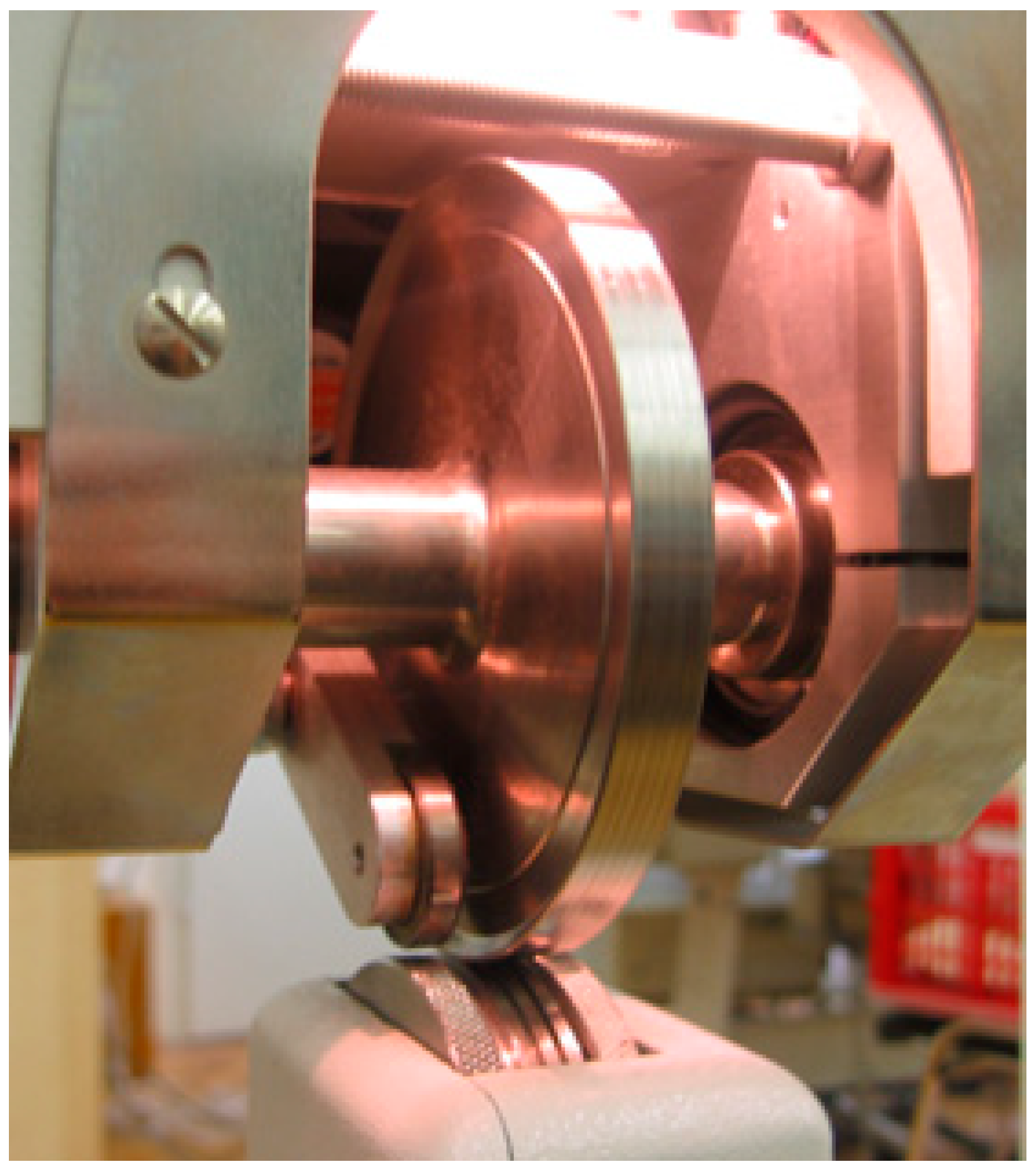
2], a group of authors attempted to improve his original initial settings in order to set up a new reaction model for calculating machine-hand welding times of synthetic polymer materials by means of ultrasonic technology using a rotary sonotrode. A part of the machine for ultrasonic welding of polymer materials, i.e., ultrasonic welding zone, is shown in
Figure 3.
The figure shows a rotary ultrasonic sonotrode (upper dominant disc) leaning against a counter roller with an engraving (lower smaller disc protruding from the machine housing). Vujasinović and Rogale [
12] described that the rotary sonotrode, 105 mm in diameter and 10 mm wide, vibration amplitude from 30 to 100 μm and with an ultrasonic generator power from 100 to 400 W. Produces ultrasonic vibrations, according Leśnikowski [
13] ranging in frequency from 35 kHz. Welding speed is adjustable from 0.6 m min
−1 to 13.6 m min
−1. The thickness of the welded composite polymer material may range from 50 µm to 2 mm, and can be varied with an accuracy of 20 µm and a welding force of up to 800 N. The linear speed of the sonotrode circumference and thus the displacement of the material, i.e., the welding speed, depends on the radius of the sonotrode and the angular speed of its rotation. During the rotation of the sonotrode, the layers of the polymer material are guided manually in such a way that the welding is performed by guiding the workpiece along the required trajectory of the weld, taking care of the permissible deviation tolerance. In this way, the simultaneous work of the machine and the worker is performed, the so-called machine-hand work, whereby the machine supplies the required energy of ultrasonic vibrations and moves the workpiece, and the worker aligns the edges of the material and manually guides the workpiece along the seam trajectory with occasional corrections in accordance with the permissible tolerance.
Due to significantly different process parameters when joining materials by the sewing and ultrasonic technology, it is not possible to apply the original expressions of W. Möller. Furthermore, it is not necessary to determine his reaction parameters based on human reactions by immediate operational measurements, since new methods have been introduced to determine them on the basis of mathematical determinants that make up the new mathematical model. The technological process itself is significantly different, especially due to the fact that the worker can reduce the sewing speed by releasing the pedal, and in the case of ultrasonic welding, he has to pre-adjust the welding speed and cannot change it during welding.
This is due to the continuous supply of ultrasonic energy at a constant displacement speed of the welded material, so that any change in the welding speed by the worker would lead to undesirable changes in the welding energy applied.
3.1. Technical, Technological and Ergonomic Parameters of the New Model
During the development of the new model, 23 process parameters were considered and applied, divided into three groups of technical, technological and ergonomic parameters.
Technical parameters of the machine used:
radius of ultrasonic rotary sonotrode rs in cm;
angular speed of rotation of the ultrasonic sonotrode, ωs in rad s−1;
maximum possible angular speed of sonotrode rotation, ωmax in rad s−1;
linear speed of the sonotrode circumference, i.e., the speed of workpiece displacement, vs. in cm s−1;
nominal welding speed or maximum possible circumferential speed in ultrasonic welding with rotary sonotrode—vmax in cm s−1;
critical radius of curvature of the weld above which the highest welding speed of the machine can be used, rkrit in cm;
delay time of the beginning of welding due to the heating of the beginning of the weld, tdy in s; and
critical radius of curvature of the weld, rzk in cm.
Technological parameters of the production process:
length of the ultrasonic weld of a segment until the tolerance of the weld accuracy is reached, wx in cm;
total length of the ultrasound weld, ls in cm;
radius of curvature of the segment of the weld seam, rz in cm;
permissible tolerance of deviation of the set and actual seam trajectory, xw1 in cm;
machine time of welding all segments of the seam with ultrasonic rotary sonotrode without correction due to the reaction abilities of the worker, tt in s;
total welding time of all segments with added times of activating the machine pedal and delay of the beginning of welding, ttot in s;
recommended linear speed of the sonotrode circumference, vprep in cm s−1; and
recommended angular speed of the ultrasonic sonotrode, ωprep in rad s−1.
Ergonomic parameters depending on the psychophysical state of the worker and the accepted values:
latent reaction time of the worker, treak in s;
number of required reactions of the worker Rp;
number of maximum possible reactions of the worker Rmax;
machine-hand seam welding using the rotary sonotrode based on human reactions, tar in s;
recommended speed of ultrasonic welding with regard to reaction abilities of the worker, vprep in cm s−1;
number of interruptions in the weld, i.e., number of welding segments in the ultrasonic weld; and
activation time of the machine pedal, tfm in s.
The values of some parameters are taken from the technical characteristics of the machine, and some are calculated according to the mathematical expressions in the next chapter and according to the defined methodical steps of the method application.
3.2. Relationship between Model Parameters
When developing a new method for determining machine-hand ultrasonic welding times based on human reactions, the starting point was W. Möller’s idea that the machine welding time of curved welds with ultrasonic rotary sonotrode tar calculated on the basis of mathematical expression for machine work t
t is increased by the reaction abilities R
p and R
max (4):
Since the linear speed of the circumference of the sonotrode vs the displacement speed of the workpiece is determined by the product of its radius r
s and the angular speed of the rotation of the sonotrode ω
s (5):
Machine-hand welding time of (straight) seam with ultrasonic rotary sonotrode t
t can be expressed by the usual mathematical expression for calculating machine work as the ratio of the total length of the ultrasonic weld ls and nominal welding speed or maximum possible circumferential speed of ultrasonic welding with rotary sonotrode—v
max (6).
By inserting expressions (5) and (6) into expression (4) the machine-hand welding time of the weld with ultrasonic rotary sonotrode can be calculated using the value of the maximum possible angular speed of the sonotrode rotation ω
max by expression (7):
Or using the value of the maximum welding speed or the maximum possible circumferential speed of ultrasonic welding with a rotary sonotrode—v
max (8).
Firšt Rogale et al. [
14] have shown the number of maximum possible reactions of the worker R
max can be calculated by expression (9):
Or using the sonotrode radius and maximum angular speed of the sonotrode rotation (10).
The latent reaction time for this model amounting to 0.2 s, and the reference length of the ultrasonic weld is 5 cm, then the number of maximum possible reactions of the worker can be expressed by the expression (11) or (12).
From the presented derivation according to mathematical expressions (9) to (12) it is observable that, when working on ultrasonic welding machines for welding polymer materials using rotary sonotrode, the number of maximum possible reactions of the worker Rmax depends on the type of the ultrasonic machine with rotary sonotrode, or sonotrode radius and the highest possible angular speed of the sonotrode rotation.
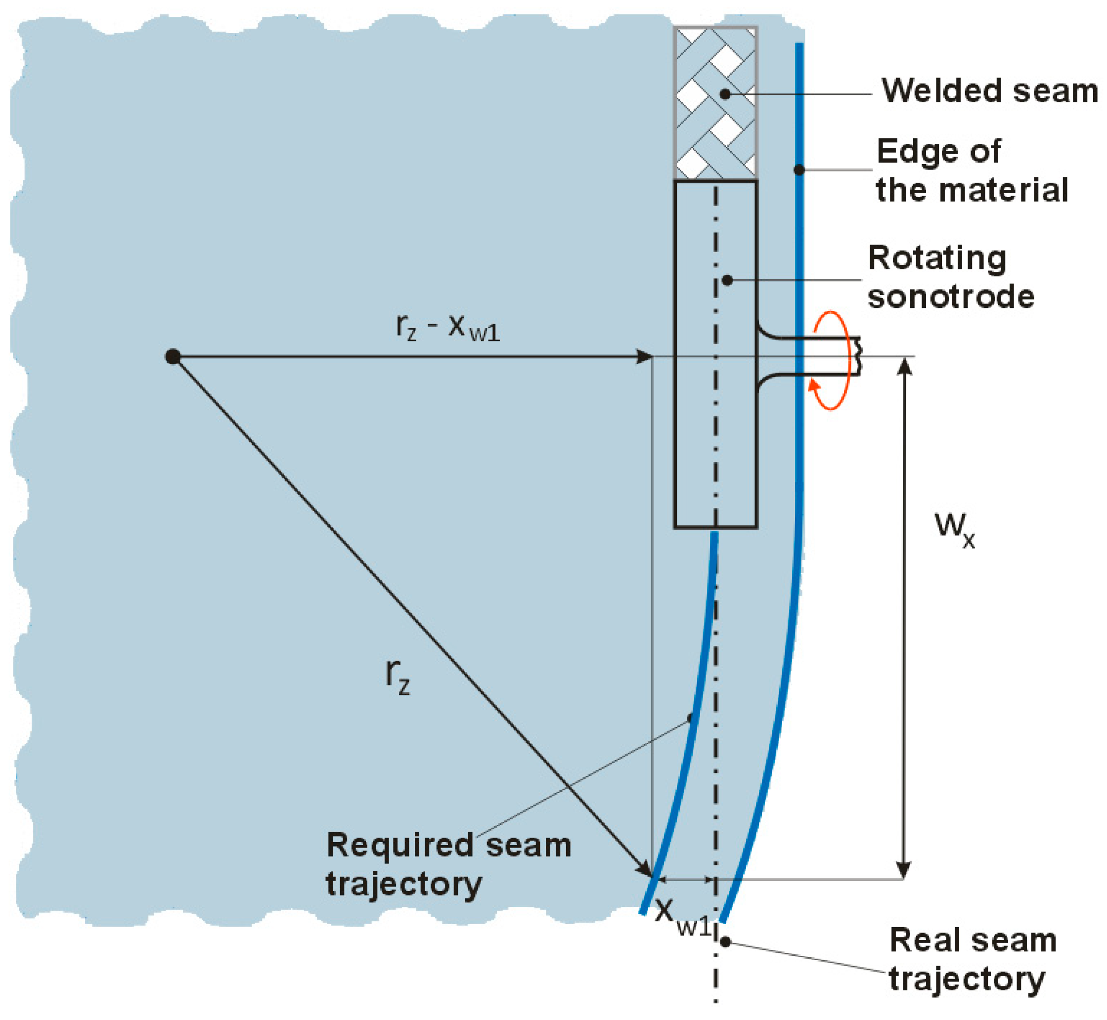
Prior to determining the number of required reactions of the worker R
p it is necessary to define the deviation between the nominal and actual ultrasonic weld observed by the worker during the ultrasonic welding as shown in
Figure 4. This figure shows a layout of welding two layers of polymer materials with a rotary sonotrode showing important technological welding parameters: radius of curvature of the segment r
z, permissible tolerance of deviations of the nominal and actual seam trajectory x
w1 and the length of the ultrasonic weld of one segment until reaching the tolerance of the weld accuracy w
x.
According to
Figure 4, the length of the ultrasonic weld of one segment w
x until reaching the given tolerance of the welding accuracy x
w1 for some radius of curvature of the weld x
w1 can be calculated by expression (13):
Firšt Rogale et al. [
12] have shown the number of required reactions of the worker for the reference length of the ultrasonic weld of 5 cm, the radius of curvature of the segment of the welded ultrasonic weld r
z and the permissible tolerance of the nominal and actual trajectory of the ultrasonic weld x
w1, is calculated by expression (14) taking into account the geometry of parameters in
Figure 4:
By inserting expressions (11) and (14) into expression (7) or (8), the expression can be determined for the calculation of the machine-hand welding time with rotary sonotrode tar (15):
The recommended speed of ultrasonic welding with respect to the abilities of the worker v
prep can be determined by expression (16):
i.e., by inserting expressions (11) and (14) into expression (16) the recommended speed of ultrasonic welding is determined by expression v
prep (17):
It is evident that the recommended speed of ultrasonic welding depends only on the technological parameters: radius of curvature of the segment of the welded seam rz and the permissible tolerance of deviations of the nominal and actual seam trajectory xw1.
The recommended angular speed of the ultrasonic sonotrode ω
prep is calculated by expression (18).
With this model, it is no longer necessary to determine Rp in tabular form on the basis of operational measurements of groups of welds with different radii of curvature and tolerances of trajectory deviations, as in Möller, but they are determined mathematically for any radius of curvature and specified tolerance. In addition, the defined expressions also show a mathematical correlation of all 23 process parameters relevant for determining the time of the ultrasonic welding based on human reactions, which is favourable for future studies of various high-tech welding methods in industrial manufacturing processes.
To determine the total execution time of the machine-hand execution time of the technological procedures of ultrasonic welding it is necessary to determine the number of segments in the weld. There can be several welding segments, and they depend on the length of the weld and the radius of curvature of the weld. After welding the first segment of the weld of length w
x according to
Figure 4 and reaching the permissible welding tolerance x
w1 (specified welding accuracy), the operator stops the rotation of the sonotrode by releasing the machine pedal, whereby the ultrasonic generator is switched off. The worker then repositions the workpiece and activates the pedal to make the other segment of the weld. The procedure is repeated until all segments of the weld have been made on the entire length of the weld ls. As there are usually several such segments, the activation and releasing time of the pedal should not be neglected. The number of seam interruptions n in the seam, i.e., the number of seam welding segments is calculated by expression (19):
It is customary to get a decimal number for n. It should be rounded to the first larger integer and is used to calculate the total welding time of all segments with the added times of pedal activation and the delay of the beginning of welding according to expression (20):
In expression (20) two parameters appear in brackets which have to be considered for each welding of a segment in a weld. These are the time of activation and releasing of the machine pedal, tfm and the delay time of the beginning of welding due to heating of the beginning of the weld, tdy at the beginning of the weld when the sonotrode is idle, and the ultrasonic generator works and heats the beginning of the weld. After the delay time for the start of the sonotrode rotation has expired, the sonotrode rotation mechanism is automatically switched on.
By establishing the interconnection model presented, it was also possible to calculate another interesting technical parameter, the critical radius of curvature r
zk. If v
max is inserted into expression (17) instead of v
prep and r
zk is excluded, (21) is obtained:
This is a parameter that is characteristic for each machine and depends on the technical parameters of each machine and the specified welding accuracy. The critical radius of curvature of welding is calculated for the given maximum welding speed and welding accuracy. This is the value of the curvature at which the welding will be performed at the highest welding speed of the machine. For smaller values of the critical radius of curvature, the recommended welding speed must be calculated and the machine must be set to this welding speed.
3.3. Methodological Application Steps of the New Model
When determining the method of using this model, it should be emphasized that it is made for each individual machine for ultrasonic welding of polymer materials and that it is necessary to know the technical characteristics of the machine used. Then it is necessary to define technological and ergonomic parameters.
Step 1: Defining and collecting parameters for the calculation
As part of the technical parameters of the machine, it is necessary to know: the radius of the rotary sonotrode, nominal (maximum) angular speed of rotation or the maximum linear circumferential speed of the sonotrode and the delay time of the beginning of the seam welding.
As part of the technological parameters, it is necessary to know: total length of the weld, radius of curvature of the weld, and the required accuracy of welding (permissible tolerance of deviation).
As part of ergonomic factors, it is necessary to know: latent reaction time of the worker and the time of activation and releasing of the machine pedal.
Step 2: Parameter calculation
The authors recommend the following order of parameter calculation:
length of the ultrasonic weld of a segment wx until reaching the specified tolerance of the accuracy of the ultrasonic weld according to expression (13);
number of welding interruptions n in the ultrasonic weld, i.e., number of welding segments according to expression (19);
number of required reactions of the worker Rp according to expression (14);
number of maximum possible reactions of workers Rmax, according to expression (12);
recommended speed of ultrasonic welding with regard to the reaction ability of the worker, vprep in cm s−1, according to expression (16) or (17);
machine-hand welding time with ultrasonic rotary sonotrode based on human reactions, tar in s, according to expression (15) or (8);
total welding time of all segments with the added activation times of the machine pedal and the delay of the beginning of welding, ttot according to expression (20) and;
critical radius of curvature rzk according to expression (21).
4. Results and Discussion
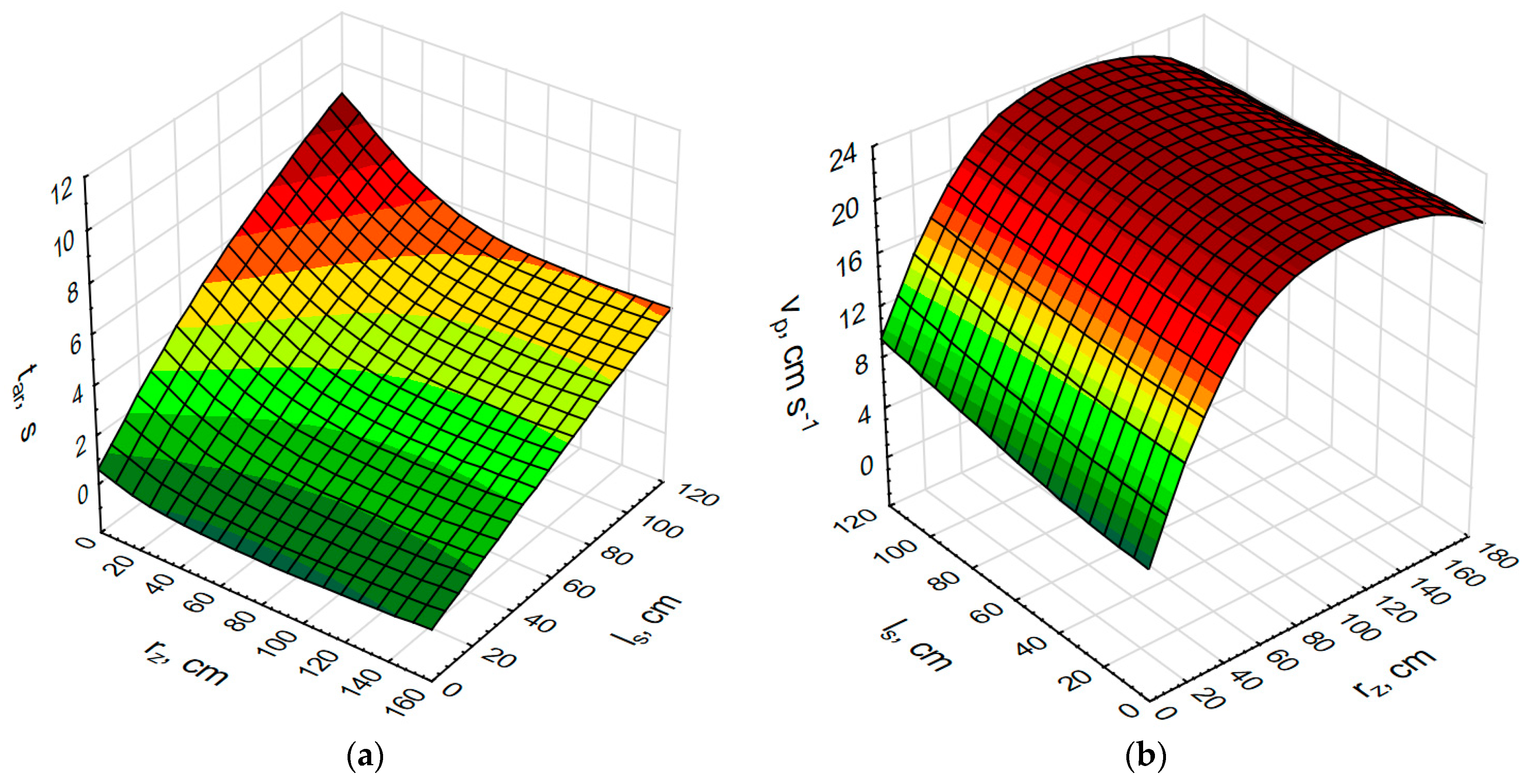
Using mathematical expressions for the calculation of machine-hand welding time tar with an ultrasonic rotary sonotrode and for the recommended speed of ultrasonic welding v
prep, and taking into account the reaction ability of the worker, their values were calculated for the lengths of curved welds up to 120 mm and for curvature radii up to 160 mm. These values are often found in ultrasound welding of waterproof clothing, thermal insulation chambers on clothing and other items made of technical textiles. The calculation was performed for three groups of permissible tolerances of deviation of the nominal and actual seam trajectories x
w1 of 2, 4 and 6 mm. For each permissible tolerance, a diagram of the dependence of machine-hand times on the length and radius of curvature of the weld and a diagram of the dependence of the recommended welding speed on the length and radius of curvature of the weld were made.
Figure 5,
Figure 6 and
Figure 7 show diagrams of the mentioned dependencies. It can be seen that the maximum machine-hand time will be required for ultrasonic welding of long welds with small radius of curvature, and the least amount of machine-hand time for welding short welds with large radius of curvature. At the same time, the machine-hand welding time decreases as the permissible welding tolerance increases,
Figure 5a,
Figure 6a and
Figure 7a.
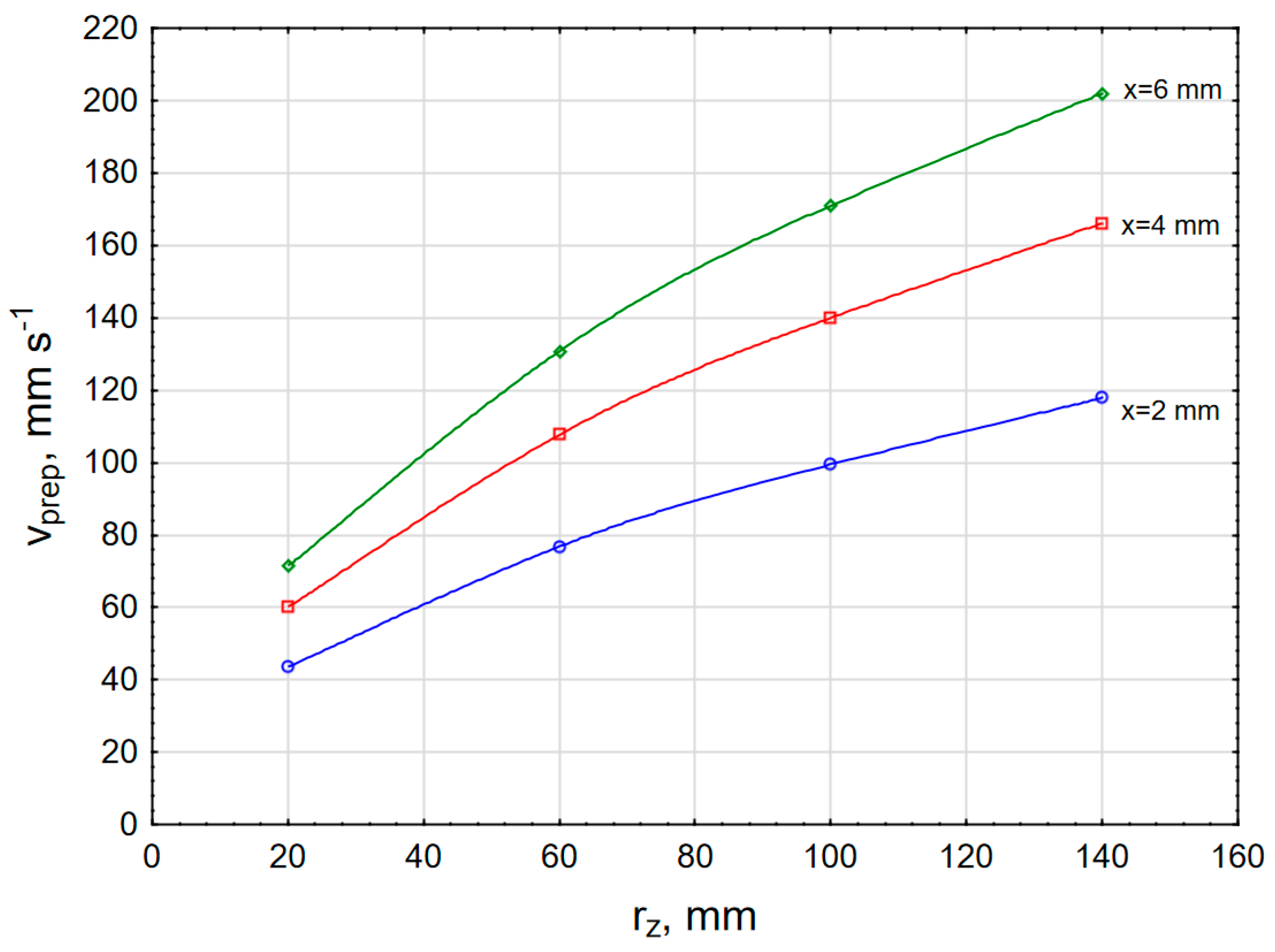
From the dependency diagram of the recommended welding speed on the length and the radius of curvature of the weld seam,
Figure 5b,
Figure 6b, and
Figure 7b, it can be seen that the recommended welding speed increases with the length of the weld. This growth is lower with lower tolerances (
Figure 5b) and higher with higher tolerances (
Figure 7b). The above diagrams show that as the radius of curvature of the seams increases, the recommended welding speed increases rapidly and reaches a value when it begins to stagnate.
The above diagrams show that as the radius of curvature of the seams increases, the recommended welding speed increases rapidly, reaching a value when it begins to stagnate. In general, the recommended welding speeds for welds with a tight tolerance are low and get higher as the permissible welding tolerance increases.
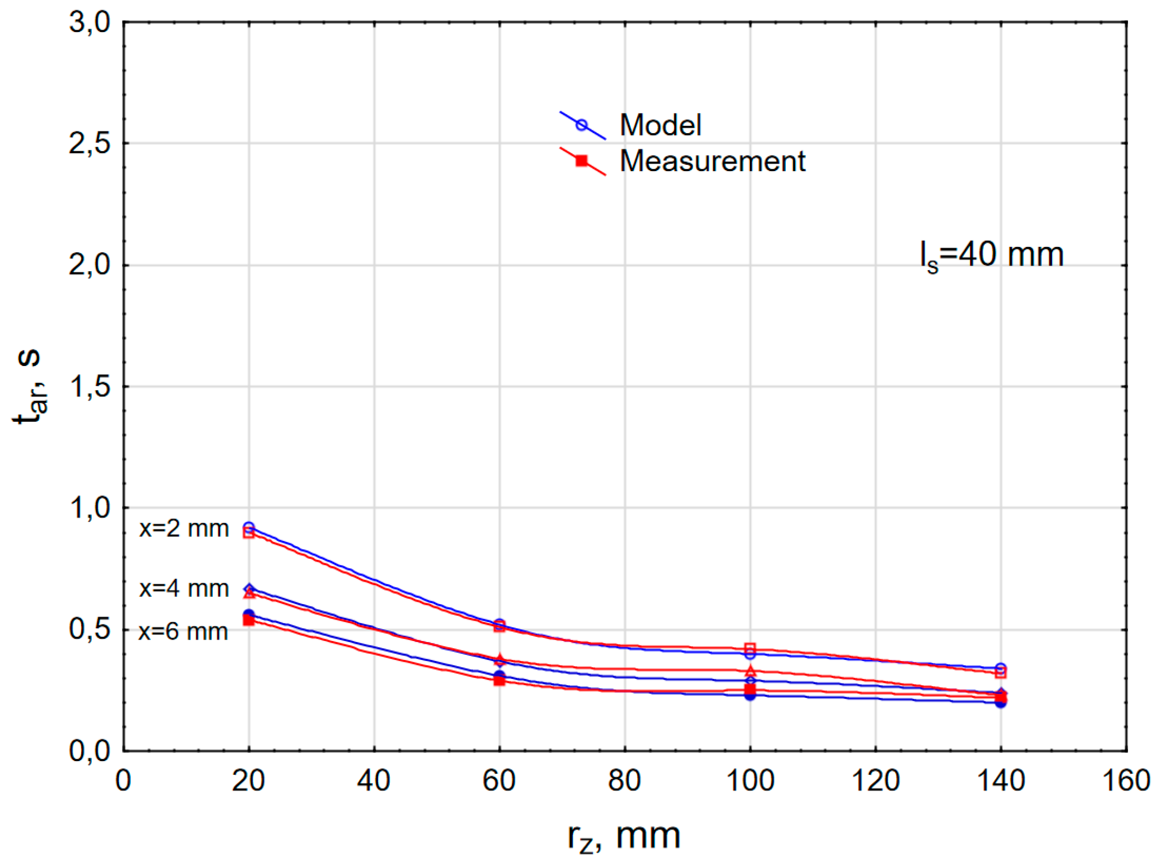
Figure 8 shows the dependencies of changes in machine-hand times of ultrasonic welding with rotary sonotrode based on human reactions for a 120 mm long seam and for a welding accuracy of 2, 4 and 6 mm according to the model (blue curve) and experimental measurements (red curve).
Figure 9 shows the same dependencies for the 80 mm long seam and
Figure 10 for a 40 mm long seam. It can be seen that the values of machine-hand times are high when welding strongly curved seams (seams with a small radius of curvature) and that these values decrease as the radius of curvature increases. All of this fits perfectly with the practical observations. Similar considerations apply to
Figure 9 and
Figure 10, but here the value execution times are shorter because the welds are shorter.
Figure 11 shows the dependency of the recommended speed of ultrasonic welding with respect to the reaction abilities of the worker, v
prep on the radius of curvature of the weld for the degree of welding accuracy of 2, 4 and 6 mm. These are in fact the highest welding speeds that can be applied with regard to possible reaction abilities of the worker and according to them the ultrasonic machine should be programmed when the radius of curvature of the weld and the required welding accuracy is known. It can be seen that the recommended welding speeds are low when it comes to strongly curved welds and high accuracy, and they increase as the curvature of the welds and welding accuracy decrease.
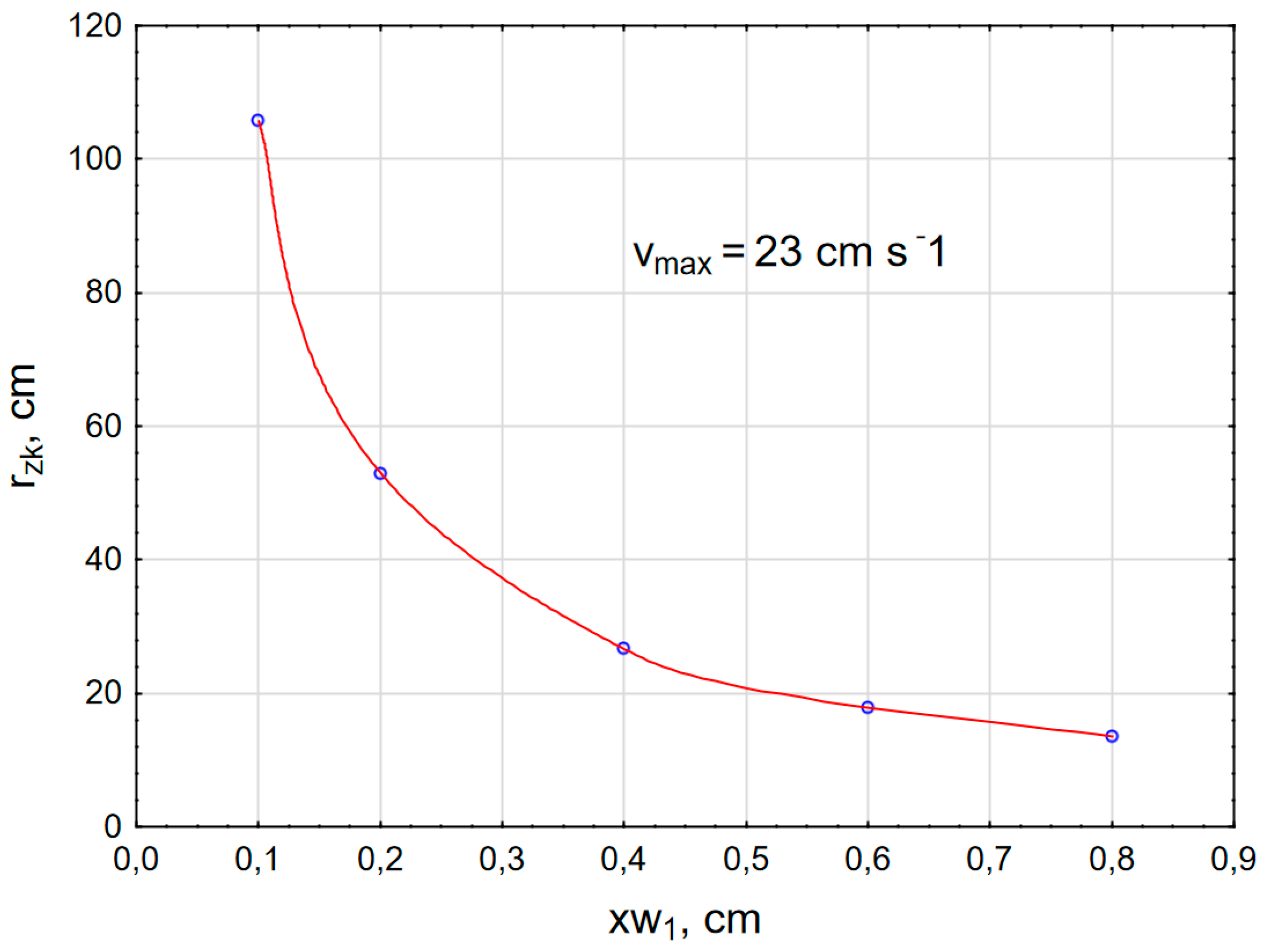
Figure 12 shows the dependence of the critical radius of curvature r
zk on the radius of curvature r
z for an ultrasonic machine with a nominal welding speed of 23 cm s
−1 and a sonotrode diameter of 105 mm. The critical radius decreases with the increasing welding accuracy. This diagram applies only to machines with the same maximum welding speed and sonotrode diameter and cannot be used for other machines with different technical characteristics.
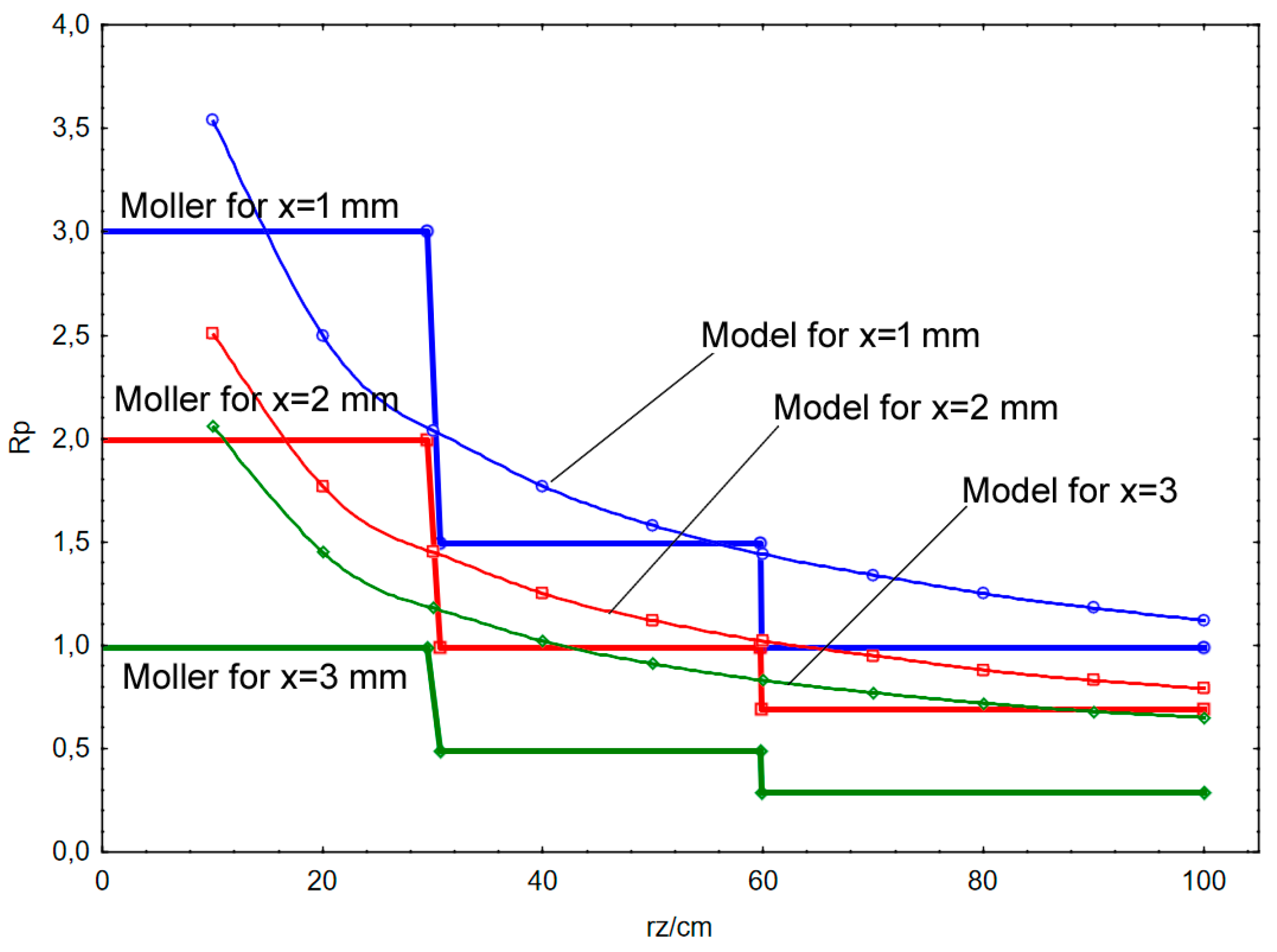
Figure 13 shows the change in the required reactions R
p according to Möller for the welding accuracy of 1, 2 and 3 mm and according to the mathematical model presented for the same welding accuracies. It can be seen that Möller’s change in the required reactions is erratic.
It is also obvious that Möller used only 3 values of machine hand time corrections for the most strongly curved seams with a radius curvature of up to 300 cm, which is very low. Nevertheless, his scientific contribution is still very great as he was the first to introduce such corrections of the basic times and pointed to their increases with a decreasing radius of curvature of the welds and with an increasing welding accuracy. The presented mathematical model does not have steps, but continuous changes that are more appropriate and accurate for application, in accordance with the presented new model and with the methodology of its application.
5. Conclusions
The paper presents and describes the claims of W. Möller, according to which a spontaneous reduction in the sewing speed by the worker occurred when sewing strongly curved the seam segments. The sewing and ultrasonic welding processes are significantly different from the aspect of the applied joining technique, but also from the aspect of workpiece guiding and joining speed adjustment. In sewing machines, it is possible to reduce the sewing speed by releasing the machine pedal when encountering more strongly curved seam segments. In ultrasonic welding it is not possible to change the welding speed because the density of the applied ultrasonic energy per unit length of the weld would be non-uniform. All these facts and significantly different welding parameters have led to the development of a completely new and original model for determining the machine-hand welding times of synthetic polymer materials using ultrasonic welding machines with a rotary sonotrode. In this way, 23 different parameters of ultrasonic welding were successfully connected by three groups of technical, technological and ergonomic parameters. On the basis of 21 presented mathematical expressions, a mathematical correlation of all the considered parameters was found and the method to apply the new model was presented.
On the basis of the mathematical expressions presented, calculations and graphic presentations of the interrelationships of the most important parameters were carried out, and the success of the model was verified by experimental measurements. An acceptable correlation was found between the value of the calculation per model and welding under real production conditions. Analysis of the application of some of Möller’s ergonomic specifications shows that for the most critical seams on garments, Möller has only three degrees of machine hand time correction, while according to the new model, the number of corrections is practically unlimited and covers all possible lengths and curvatures. Likewise, Möller’s observation of the spontaneous reduction of the welding speed in the model could not be applicable, so the concept and parameter of the recommended welding speed, which is calculated and entered into the process microcomputer before welding starts, was introduced. The mathematical expressions of the new model themselves differ significantly to Möller’s mathematical expressions and tabular data. In this way, the new model retains its originality and applicability, while at the same time its contribution to Möller’s research is recognised.
So far there has been no method for determining the machine-hand welding times using ultrasonic welding machines with rotary sonotrode and this is the reason why this paper offers, for now, the first and only solution. There are no recent scientific and professional papers.


