1. Introduction
While playing on an acoustic piano, a pianist refers to an essential sensory information called the
touch. The touch is largely caused by the dynamic behavior of the piano action, represented in
Figure 1. Present-day digital keyboards offer the possibility to nuance the sound and feel a feedback thanks to simplified passive mechanisms. However, the result is far from reproducing the
touch quality of the actions equipping traditional acoustic pianos.
This paper is based on a previous work [
1]. Compared to [
1], the multibody approach is described and the piano action model is presented. Interesting results are achieved with both this model and a simpler one, showing the easiness to switch from one model to another. Furthermore, the sensors implementation is detailed with a specific combination of two position sensors for the key movement.
In the literature, multiple attempts have created a force feedback key based on passive elements but few proposed a device that actively replicates the feeling of touch.
In 1990, Cadoz [
2] designed a multiple force feedback keyboard. His haptic device used a custom sliced motor for each key along with contemporary technologies. It includes two mechanical morphologies to be reproduced: the piano or organ. No details are given about the models.
In 1993, Gillespie [
3] worked on virtual environment simulations to reproduce the grand piano feeling. Focused on modeling tools able to take into account the changing kinematic constraints, the authors used simplified descriptions of the action. The two models only include the key and the hammer, under two motion phases. An electromechanical hardware integrating voice-coil motors provided the haptic rendering.
More recently, in 2006, Oboe [
4] demonstrated that a feedback is feasible using a reduced dynamic simulator with event management. Furthermore, he has built a prototype using low-cost components as a voice coil motor taken from standard hard disk drives. However, the dynamic model only considers the hammer and the key.
In 2007, Lozada [
5] developed a haptic interface with an embedded system based on a magneto-rheological fluid. Thanks to a complete analytical model, the system was able to damp the key motion according to a complete dynamic description of the piano action behavior. Six degrees of freedom are computed in the dynamic model, including friction force laws and unilateral contacts. The main drawbacks is due to the actuator passivity: the magneto-rheological fluid brakes the movement but is unable to apply an active force on the key.
In 2013, Horváth [
6] presented an analytical and experimental investigation of piano action modeling. The handmade analytical model is
a priori characterized by measurements on a real action. It considers the check and latching phases independently without considering a real-time functioning model. Using a custom-made voice coil actuator, the authors also focused on a detailed study of the magnetic field inside the device.
In 2016, Miedema [
7] built a prototype that reproduced different force-displacement piano profiles via the use of a hard disk voice coil. The final layout differs from an usual piano key. Force profiles that were pre-measured on acoustic pianos are used instead of a dynamic model of the action.
With the same approach, Adamou [
8] proposed in 2019 a reproduction of a keyboard instrument touch. First, he measured the static and dynamic forces acting on the key while being pressed and depressed. Second, he used low cost components to implement a prototype that can reproduce the measured force profiles. No experimental results have been shown so far.
To summarize, various attempts were made to design a force-feedback piano key using different approaches, layouts and actuation types. In this work, we present the design and the validation of a haptic feedback device aimed at reproducing the touch of a grand piano action. As far as we are concerned, our approach brings three main advantages compared to previous solutions. (i) First of all, our device keeps the key main physical characteristics in terms of dimensions and tactile feeling. Most previous research has resulted in devices quite different from a piano keyboard (i.e., metallic and shorter key [
2], rotoid key joint [
5], ...). By physically keeping the original key, it enhances the quality of the human interaction as it maintains the conditions of play close to that of an acoustic piano. This paper proposes a solution that preserves the key physical characteristics, as view and felt by the pianist.
(ii) Contrary to the simplified models used in preceding attempts [
3,
4,
6,
8], our dynamic model [
9] benefits from a multibody approach to compute very precisely the action force to be reproduced by the haptic device. This model perfectly represents the real morphology of the system with all its physical parameters. Moreover, it is fully configurable. For example, the (de)regulation of the action can be processed in real time. In addition, other multibody models of any piano action can be computed inside this haptic device. None of the previous solutions used such a detailed piano action dynamical model, which is essential to capture the action transient dynamical behavior.
(iii) Furthermore, the homemade linear actuator is built as a voice coil based on a presizing step and then on FEM simulations to fulfill the dynamic requirements. Its functioning has been ascertained through experimental validations. Few of previous solutions [
4,
5,
7] showed experimental characterizations, and none presented results of the device feedback during a real key struck. On top of that, none of the previous solutions showed the ability to swap between several models. In this paper, two models are used in the prototype and validated, see
Section 3.
The paper is organised as follows.
Section 2 describes the approach followed: in
Section 2.1, the haptic principle is presented with the prototype set-up and its specifications.
Section 2.2 introduces the multibody modeling of the grand piano action. Description and analysis of the sensors used are explained in
Section 2.3. The electromagnetic linear actuator layout is developed in
Section 2.4.
Section 3 deals with the results of an experimental validation with the prototype.
Section 4 proposes a discussion on the results and the approach. The last
Section 5 concludes the paper and suggests future improvements and perspectives for the prototype.
2. Materials and Methods
2.1. Haptic Piano Key
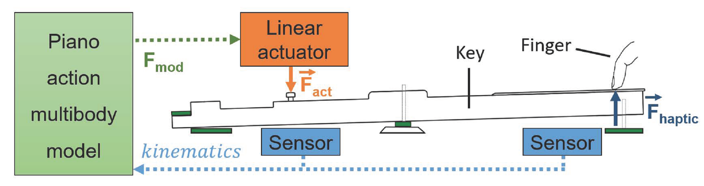
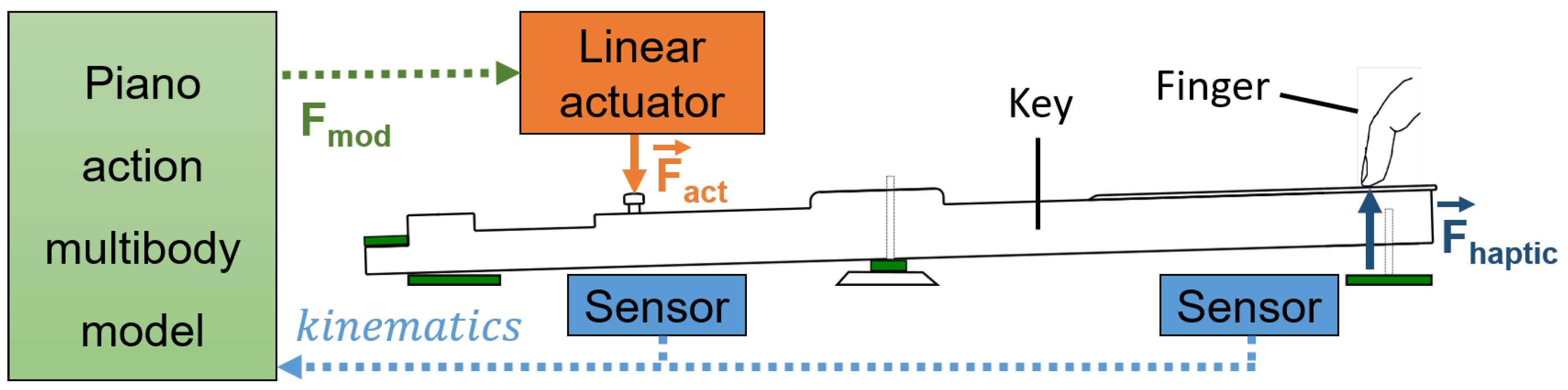
As depicted in
Figure 2, the idea consists of replacing the piano action by a linear actuator which will apply on the key the same force
as that produced by the action. Assuming that its dynamic model of
Section 2.2, driven by the key kinematics captured by position sensors, is able to compute in real time the force on the key
, the electromagnetic linear actuator of
Section 2.4 transmits the corresponding force
to the key.
Consequently, the force felt by the pianist’s finger should be identical to that of a real acoustic grand piano. In the proposed design, most of the key characteristics are preserved, with the same felt stops, pivot, visual aspect and tactile feeling. Its mass, inertia and center of mass have been modified only slightly due to the actuator-key assembly.
2.1.1. Specifications
To be efficient, the proposed haptic system requires the force feedback to be continuously applied to the key. Because of the different sensors in the human somatosensory system [
10], the update rate of the haptic rendering should be high enough. Usually, a frequency of at least 1 (kHz) provides a realistic and stable feedback. This implies the actuator to act less than 1 (ms) [
11] after the corresponding key kinematic capture.
When playing, the amount of force that the pianist applies to the key varies widely depending on the nuance, but also on the pianist experience [
12]. High peaks, up to 25 (N), at
fortissimo are possible between the pianist finger and the key [
13]. In some cases, the high dynamics of a pianist playing may cause the reaction force on his finger to vary from 0.5 (N) up to 38 (N) in a few milliseconds [
14].
Askenfelt extensively measured the kinematics of a grand piano action [
15,
16] with a focus on timing properties and key-hammer movement. It follows from these observations that the key motion can reach a speed of 0.6 (m/s) and that the complete key up-and-down motion can last less than 100 (ms).
In addition, the creation of the haptic device involves several challenging developments:
Conserve the key main characteristics: dimensions, mass, tactile feeling as well as visual aspects. Indeed, keeping the pianist environment close to the grand piano conditions enhances the quality of the physical interaction [
17];
Limit various design parameters: mass, volume and energy consumption of the device;
Fit the actuator within the key width: As a piano keyboard is composed of 88 keys, this specification will allow the device to be assembled within a multi-key prototype.
2.1.2. Experimental Set-Up
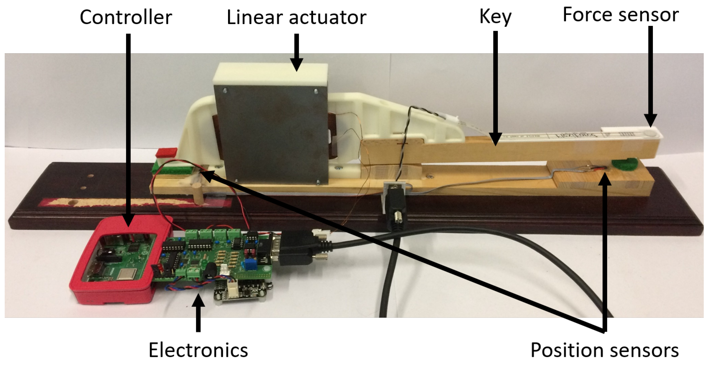
The prototype is built from a real acoustic piano key for which the action is outright suppressed and replaced by the designed actuator, see
Figure 3. The associated embedded controller computes, via a multibody model, the force to apply to the key, based on the sensors measurements, as depicted in
Figure 2. The external force sensor placed at the key front is not required for the prototype functioning, but can be used for futures validations.
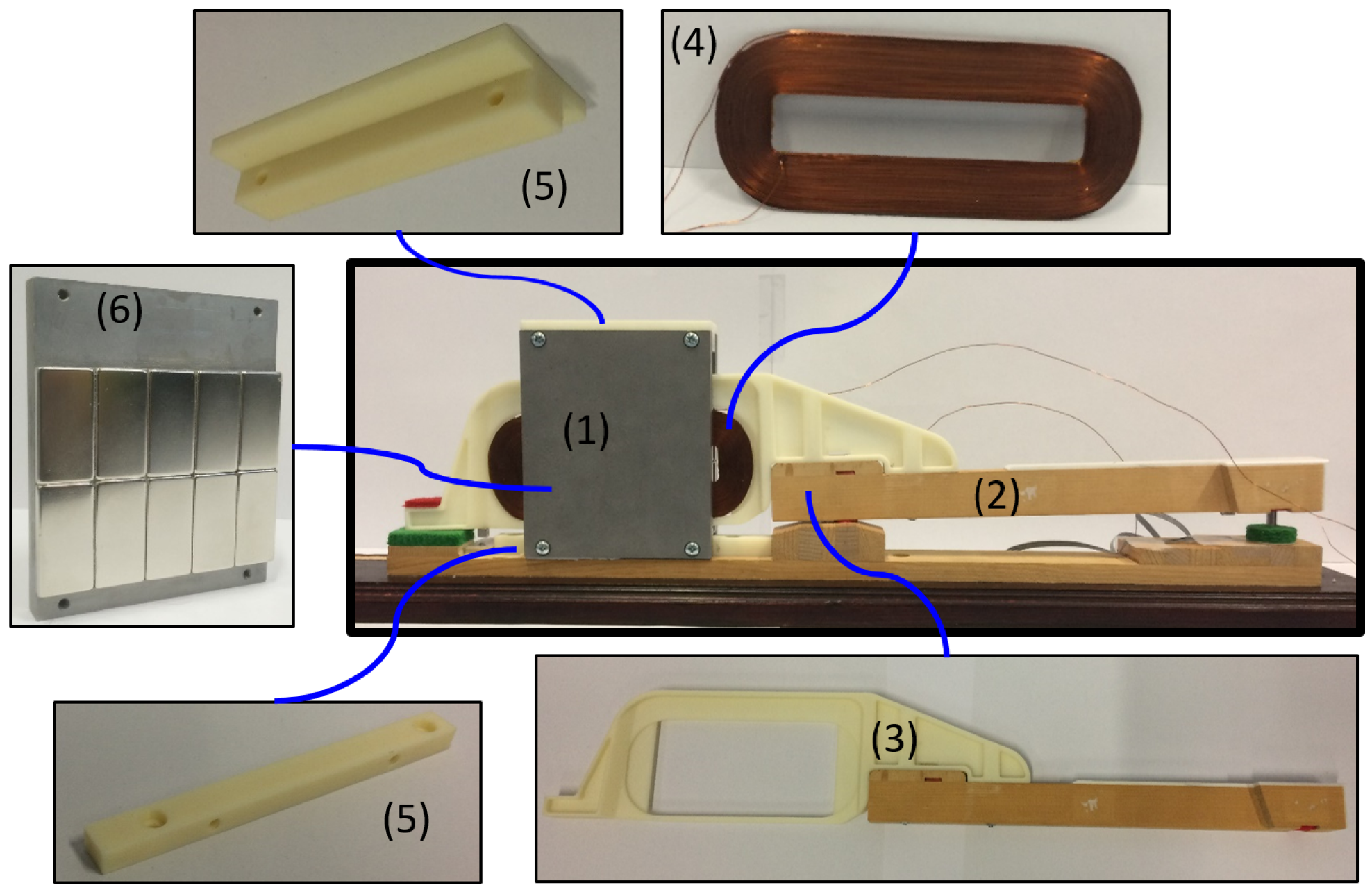
Figure 4 shows the actuator main components. An Additive Manufacturing Printed (AMP) piece, called coil support (3), makes a rigid connection between the key (2) and the coil (4), ensuring the force transmission from the actuator (1) to the user’s finger via the original wooden key. AMP technology was chosen for its ability to achieve complex geometries and for its low mass density, using the common thermoplastic polymer ABS as material. The actuator structure is made of two iron walls (6) on which permanent magnets (PMs) are glued. The two sides are facing each other and two spacers (5) ensure a constant gap in which the coil is inserted.
2.2. Piano Action Modeling
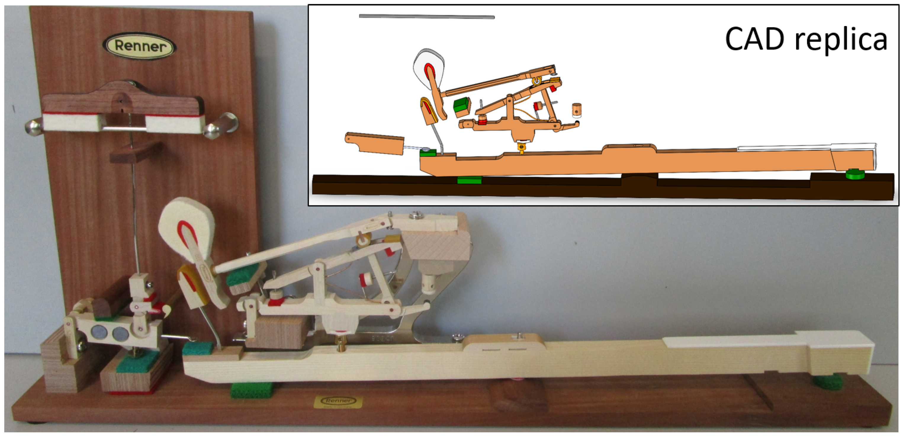
Invented at the beginning of the 19th century by the French instrument maker Sebastian Erard, the
double escapement action of
Figure 1 is now found in every grand piano. This section presents the basic principles of multibody approach using this specific action as illustrative case. Needless to say, the same modeling technique can be applied to any action topology.
2.2.1. Double Escapement Model
The model of the grand piano action [
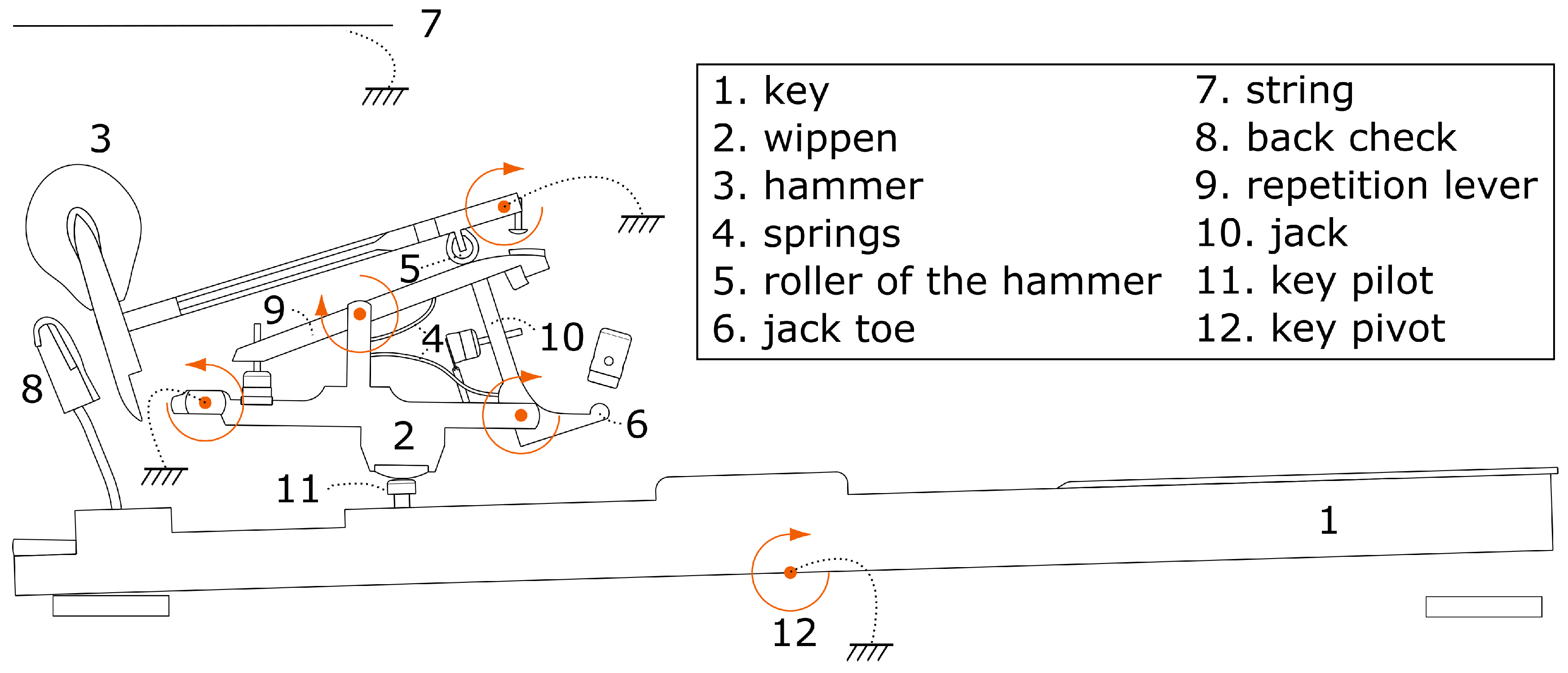
9], containing the main elements visible in
Figure 5, is based on the following reasonable hypotheses:
the motion is planar;
the revolute joints are geometrically perfect, i.e., no backlash;
the rotation between the key and the keyboard fixed frame is considered as a perfect revolute joint around a fixed axis, namely the key pivot number 12 in
Figure 5;
the string force on the hammer is assimilated to that an equivalent vertical spring-damper system, i.e., a force transmitter;
the interaction between the damper and the string has not been modeled. The damper is the element responsible for muting the sound by blocking the string once the key is released. Its motion plays a secondary role in the feedback touch.
Let us note that the force applied by the action on the key is located at one point on the key pilot, number 11. in
Figure 5, between the key and the wippen.
In
Figure 5, the five degrees of freedom of the grand piano action are represented by circled arrows. Three bodies out of five are articulated on the keyboard frame: the key, the wippen and the hammer; while the jack and the repetition lever rotate with respect to the wippen. Two return springs—4. in
Figure 5—and several stops condition the motion of these bodies.
The detailed functioning of the action can be found in the literature [
9,
18]. For the scope of this work, an important point is that all the contacts and forces occurring in the action are somehow felt by the pianist when pressing the key. This force perceived by the finger highly contributes to his feeling called the
touch.
The multibody model of the piano action was recently developed and its kinematics experimentally validated in our lab [
19].
2.2.2. Multibody Approach
Multibody dynamics is used in engineering to predict the motion of any kind of polyarticulated systems composed of bodies connected by joints. Using the symbolic multibody software Robotran [
20] which uses a relative joint coordinates approach, the Newton-Euler equations of motion can be produced and then solved for each body of the system.
More precisely, the so-called
direct dynamics of a multibody system described by the relative coordinates is the computation of the generalized joint accelerations
for a given configuration (
q,
) of the system to which forces and torques are applied. Synthetically, the equations of motion can be written in the following well-known form.
where for a system of
n joints,
q are the relative generalized positions coordinates;
are the relative generalized velocities coordinates;
are the relative generalized accelerations coordinates;
M is the symmetric generalized mass matrix of the system;
c is the non linear dynamic vector which contains the gyroscopic, centripetal, Coriolis and gravity terms as well as the contribution of external forces and torques ;
gathers together the dynamic parameters of the system, i.e., the masses, center of mass and inertia matrices;
Q isolates the generalized joint forces and torques, i.e., the effort in the direction of the joint motion.
The resolution of the linear system (
1) provides the joint accelerations
. Velocities and positions are then found by time integration to find the motion of all bodies. Finally, all the forces in the system are computed.
As presented in this section, a piano action can be modeled by a multibody approach to take into account the complex mechanism morphology. By solving the equations of motion (
1), the dynamic force
in
Figure 2 applied by the wippen to the key can be computed, given an imposed key motion.
2.3. Sensors
To perform active control on the device, its position has to be measured in real time. This is achieved using 2 Hall effect sensors Allegro A1301 [
21] placed in opposition on the key in
Figure 3, one at the front and the rear, measuring respectively the voltages
and
.
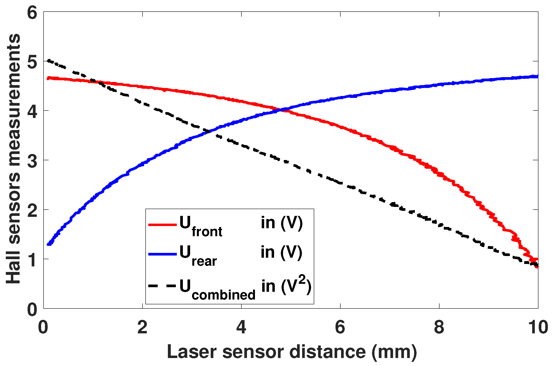
Hall sensors use magnetic field measurements which is not linear versus displacement. However, a chosen combination
between
and
allow obtaining experimentally a linear relation:
where
k is a proportionality factor determined by calibration. The
can then be converted to a position measurement and finally to the key angle via simple trigonometry. The
Figure 6 shows the corresponding curves, for a slow movement of the key.
For this validation, a laser sensor SICK OD2-P30W04IO [
22] measured the key vertical displacement precisely but with a response time above 1 (ms), which is too slow for a real-time application.
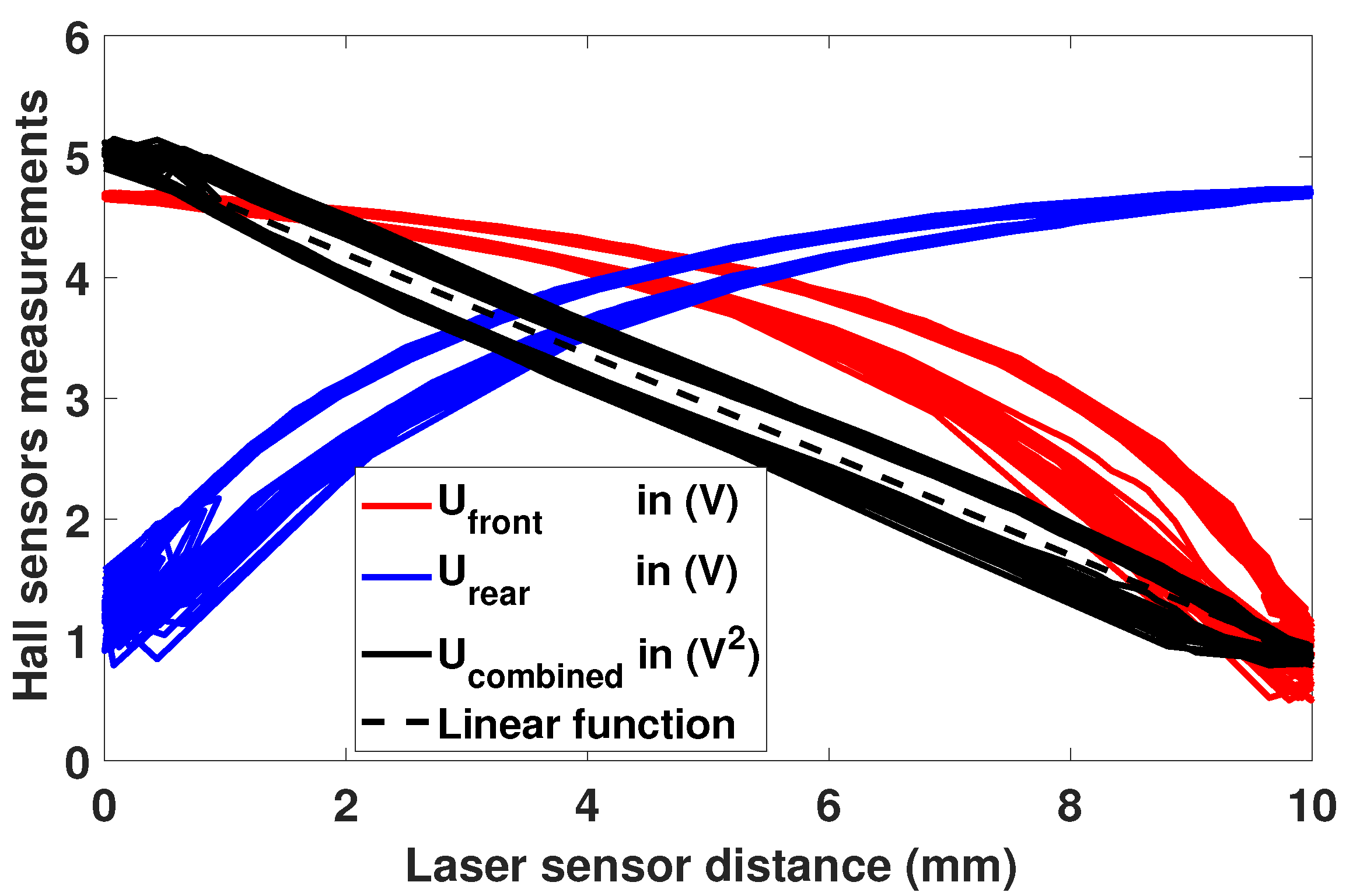
Furthermore, when faster up-and-down movements are measured, a hysteresis phenomenon appears in
Figure 7. The resulting combined measurements can still be approximated by a linear function. The maximum deviation between the linear function and
represents 8% of the total measured value range.
These Hall effect analog sensors are sampled at high frequency, 23 (kHz) for our device. However, the noise in the key position measurements has to be filtered, as it induces errors in the velocity computation. Indeed, starting from the position, a numerical time derivative is used to compute the key velocity, which is needed as the kinematic input of the multibody model described in
Section 2.2.
For this first study, a simple but efficient linear regression filtering approach is applied, as revealed in
Section 3.3.
2.4. Linear Actuator Design
The device actuation is achieved using a custom linear electromagnetic actuator, and more specifically a
voice coil. Several previous works [
6,
7,
8,
23] used the same kind of actuation. Electromagnetic actuators prove remarkably adaptable to the challenges of modern digital instrument design [
24]. The actuator needs to fulfill the specifications of
Section 2.1.1 in order to reproduce accurately the force feedback feeling of touch. This section brings out the actuator design procedure that follows three steps: analytical presizing, verification by FEM and simulation analysis.
2.5. Working Principle
A current flowing in a conductor placed in a magnetic field creates a proportional force:
where
is the created force (N),
i the current (A) in the conductor,
l is its length (m) and
B is the magnetic field (T).
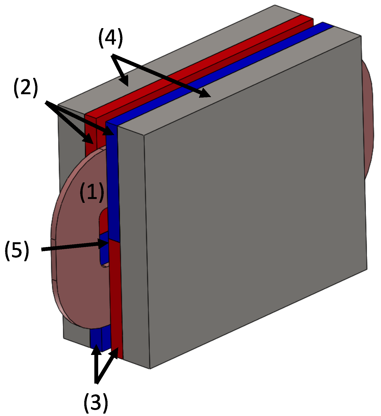
Figure 8 shows the PMs that create the magnetic field and the iron pieces that are placed around the magnets to close their magnetic field. The copper coil is attached to the piano key on which the actuator force is acting.
The actuator is considered linear because of the small key rotation angle of 1.7 (
) maximum. The actuator analytical equations are the same of a classical DC motor but adapted to a linear movement:
where
V is the voltage (V) applied on the coil,
R its resistance (
),
i the electrical current (A) in the coil,
L its inductance (H),
is the force constant (N/A),
the coil vertical velocity (m/s) and
is the force (N) developed by the actuator through (
3).
of (
5) is proportional to the current
i and independent of the position because of the actuator morphology and the coil small displacement. A coil—considered of a constant length—is placed inside a—assumed constant—magnetic field, and therefore the formula of (
3) simply becomes (
5).
If the magnetic field
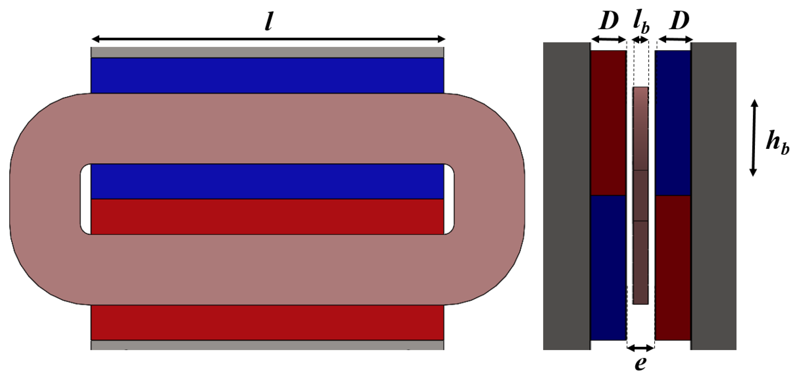
B of the PMs is considered purely normal, the field is assumed to be constant between the magnets and null outside. This constant magnitude can be expressed as:
where
is the remanent magnetic field (T) of the PMs,
e is the distance (m) between opposite magnets and
D is their width (m).
Considering this hypothesis and using (
3) and (
5), one can find the relationship between
and the magnetic field
B:
where
N is the number of turns in the coil. Indeed, the force
will be proportional to the current
i and the magnetic field
B but also to the coil wire length, which is
. The constant
can be deducted from the actuator model of (
7) or from experimental measurements, see
Section 3.1.
For the optimal design of the next section, a current density j of 5 (A/mm
2) inside the coil is considered with a filling factor of 0.5.
N will be determined during simulation analysis in
Section 2.6 to adjust the current and voltage values.
2.5.1. Optimal Design
An optimisation based on the analytical model of (
4) and (
5) and performed by a genetic algorithm is used to size the actuator.
The two optimisation variables are the coil thickness
and height
represented in
Figure 9. A constant air gap of 1 (mm) on each side is imposed to prevent contact between the moving coil and the magnets.
l is the total length, imposed to 10 (cm) as we assume that the actuator fits into the initial key length.
D is the magnet width, which will depend on coil thickness
.
The objective function to be minimized is the actuator energy dissipation (J) for a specific desired force profile.
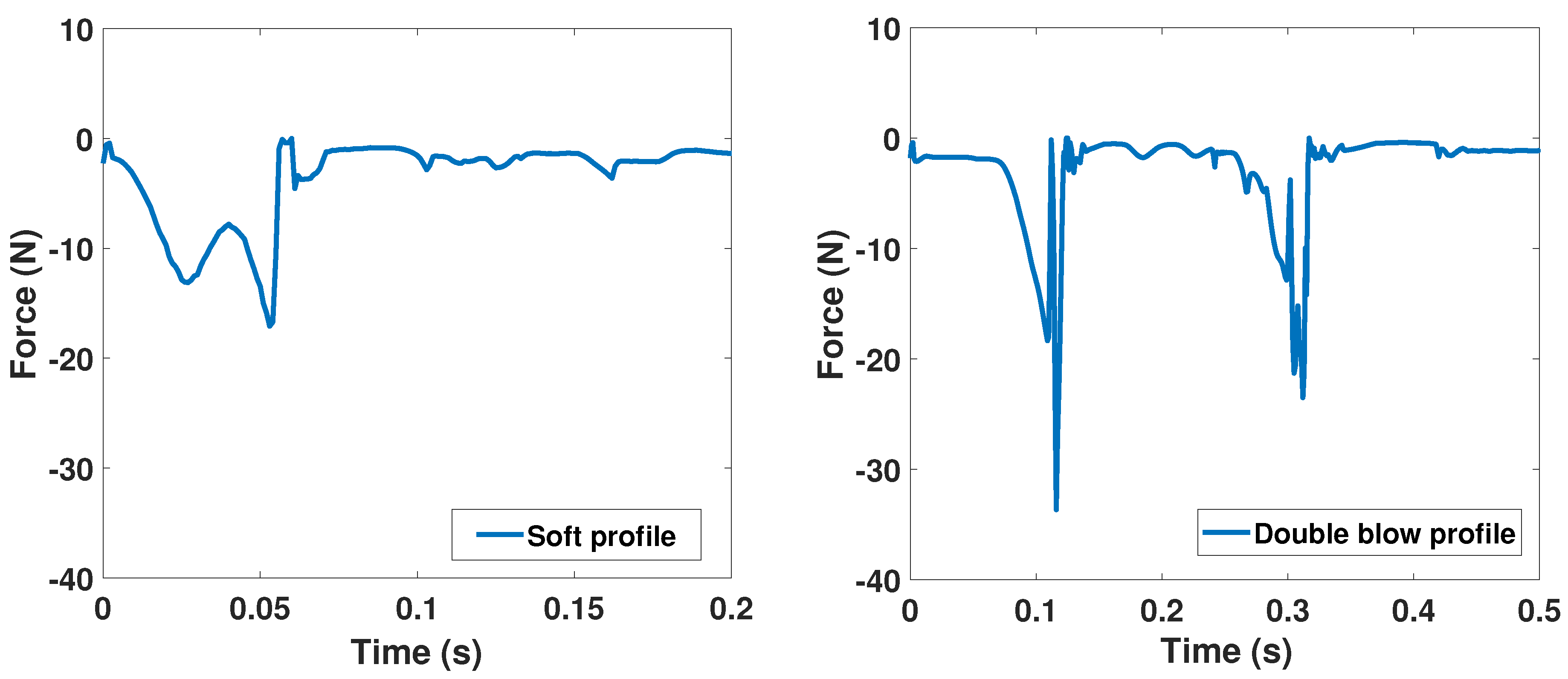
For this optimisation, two different force profiles corresponding to
of
Figure 2 have been used. These two are shown in
Figure 10, one with two high intensity peaks corresponding to a
double blow play and the other with a
softer play. The
double blow profile, which is a highly demanding one dynamically speaking, allows to cover most of pianists possible inputs. The
soft profile corresponds to a case in which the key is struck and afterwards remains pressed at the key full dip. Optimising with these two profiles ensures the actuator ability to reproduce the complex dynamics happening in a piano action.
To complete the optimisation process, two constraints have to be taken into account.
Key thickness is the maximum width of the actuator:
Coil mass m, which depends on
and
, should not increase the key mass:
Iron pieces width is not included in the first constraint as, in the case of adjacent keys, the magnetic field will extend on the neighboring PMs.
The optimisation problem can be mathematically formulated as follows.
The results of this presizing step can be found in
Table 1. The final values
are small and differ logically depending on the applied force profile. Even for a very demanding output, the mean power dissipated due to Joule losses
stays below 0.22 (W), which will not cause overheating risks on the coil.
2.5.2. FEM Validation
FEM simulation allows verifying that such pre-designed actuator meets the specifications of
Section 2.1.1. Phenomena such as border effects and magnetic saturation inside the iron pieces that were neglected in the analytical model of the previous section are now taken into account. Note that, as the actuator is symmetrical around the two planes, the FEM analysis has been computed on the quarter of the actuator only, in order to divide by four the FEM computation time. By imposing the adequate boundary conditions on the symmetry planes, this is equivalent to modeling the entire actuator.
DC force is developed when applying a constant current in the coil. When the key is moving, the coil may comes closer to the magnets border where magnetic field is slightly reduced. This implies a negligible force reduction of 1.5% for a maximal displacement of 7 (mm) and for an arbitrary coil current density of 5 (A/mm2).
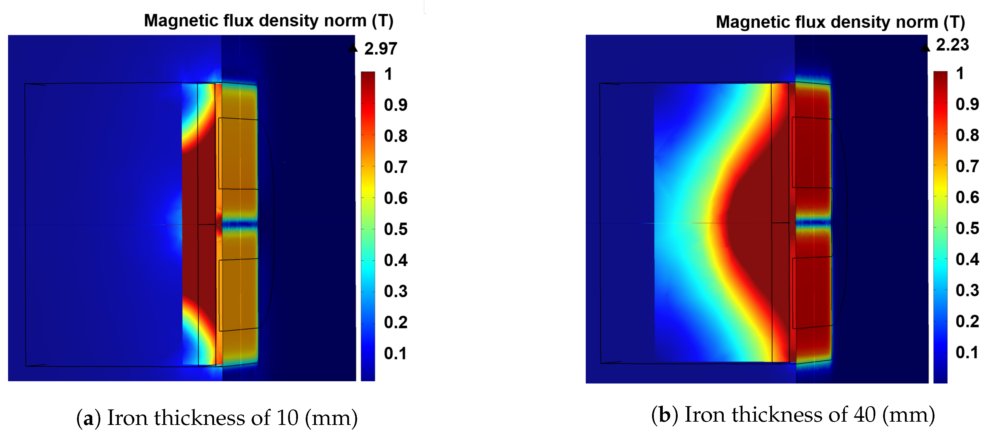
Iron pieces are disposed around the magnets in order to close their magnetic field. The magnetic field through the iron will saturate depending on the iron thickness. Consequently, the air gap magnetic field will be reduced as shown in
Figure 11. With the iron thickness of 40 (mm), the magnetic field reaches 95% of its maximum value. In the prototype, with iron pieces 12 (mm) thick, the magnetic saturation causes a reduction of 18% of the magnetic flux density. The obtained field value in the air gap is 0.75 (T). For future works, in case of several adjacent keys, the iron pieces are replaced by the magnets of the adjacent actuators. Therefore, our actuator still fit in one-key width.
2.6. Simulation Analysis
Actuator theoretical behavior is developed using its constitutive Equations (
4) and (
5) and parameters found thanks to FEM validation.
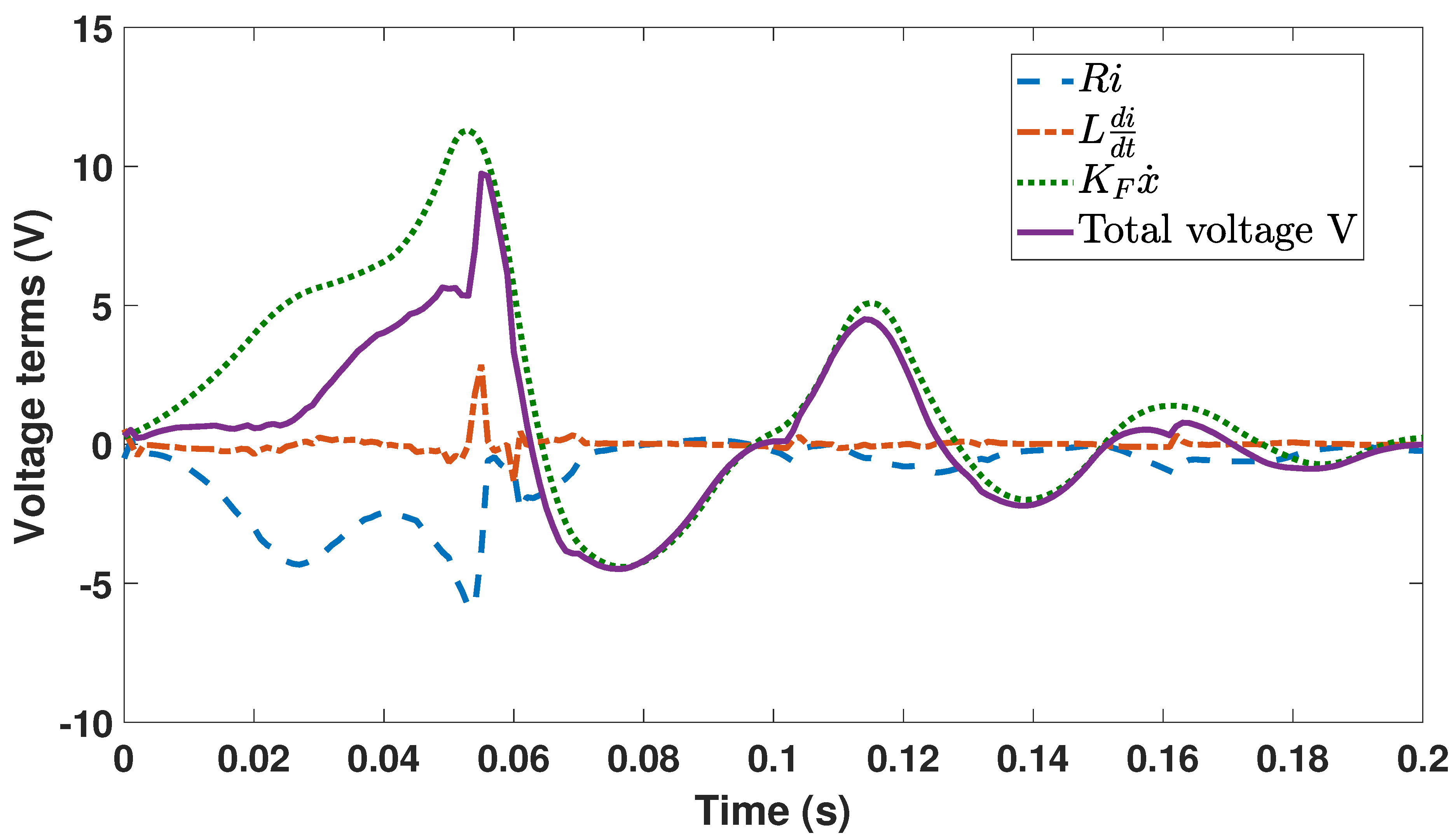
Figure 12 depicts the examination of all voltage terms which correspond to the
soft force profile of
Figure 10. The dominant term appears to be the
back-emf . Most of the time, the total voltage V has an opposite sign compared to the current, observable by the
term in
Figure 12. This means a negative electrical power that illustrates the actuator braking mode.
No explicit constraints are imposed about maximal current or voltage during the optimisation. For a copper conductor diameter of 0.33 (mm) and a filling factor of 0.5, the number of coil turns is imposed at N = 218 to keep the voltage and current values under usual range of maximum 2 (A) and 15 (V).
Globally, the actuator force
is able to follow the required output
both in amplitude and in dynamics, see
Figure 13, for the two force profiles considered. The difference between the red and the blue curves is due to the coil dynamics:
where
is the coil acceleration (m/s
2)
g is the gravity constant (m/s
2) and
is the coil mass (kg). Indeed, the actuator needs to develop the model force
as well as to counteract its own dynamics due to the coil mass.
Figure 13 illustrates that the coil dynamics is non negligible because high values are reached, especially for the double blow. Equation (
8) has been taken into account to compute the current
i in
Figure 12 according to (
5).
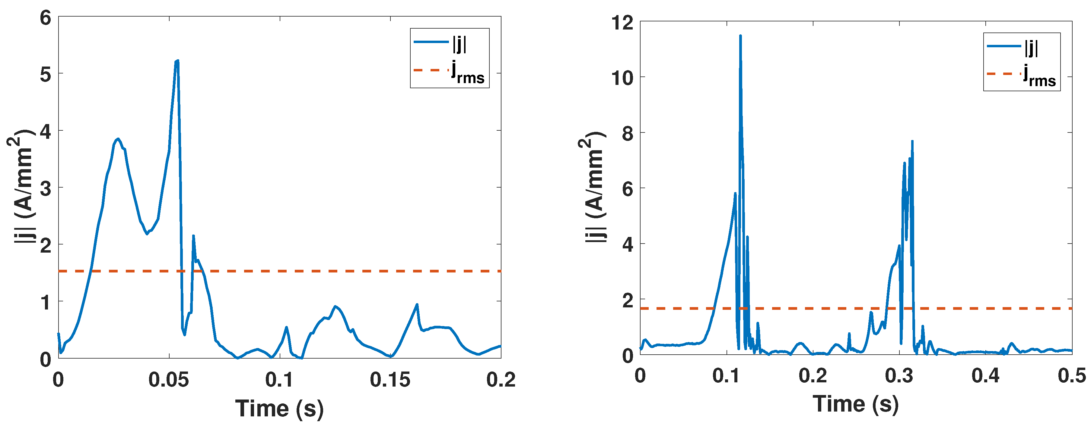
As shown in
Figure 14, Root Mean Square (RMS) values of coil current density
for the two profiles is less than 2 (A/mm
2). In fact, the maximum j stays low for this topology. To improve the actuator design and decrease its size, the maximum current density in the coil could be explicitly constrained at a higher value during the optimisation process. In this case, more investigations are needed to study the actuator thermal behavior to evaluate this maximal j.
3. Results
This section is dedicated to the experimental characterisations of the device. First, an analysis of the actuator parameters is performed. Second, the haptic prototype is validated dynamically with a simple multibody model. Finally, the system is validated with the double escapement piano action.
3.1. Actuator Parameters
As presented in
Table 2, main actuator parameters can be measured, which provides values that seem close between the three design steps: presizing, FEM and measurements. However, some differences can be observed.
Coil is lighter in the prototype due to the simplified geometry used during optimisation. Hence, the final key inertia is finally only increased by 3%, compared to a grand piano key. Electrical resistance has increased, possibly because of the coil physical connections. Inductance value does not seem to vary substantially.
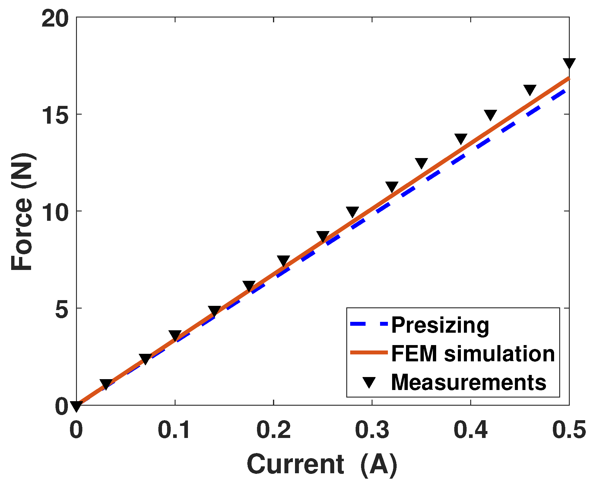
The force constant
in (
5) is estimated by measuring the actuator force for different values of input current
i. The model value of (
7) gives the theoretical value of 32.7 (N/A).
Figure 15 presents the force-current relation, with a measured mean value around 35.72 (N/A), for a constant horizontal key position. The differences between the results comes from the number of coil turns (more than 200) which slightly differs in the three steps.
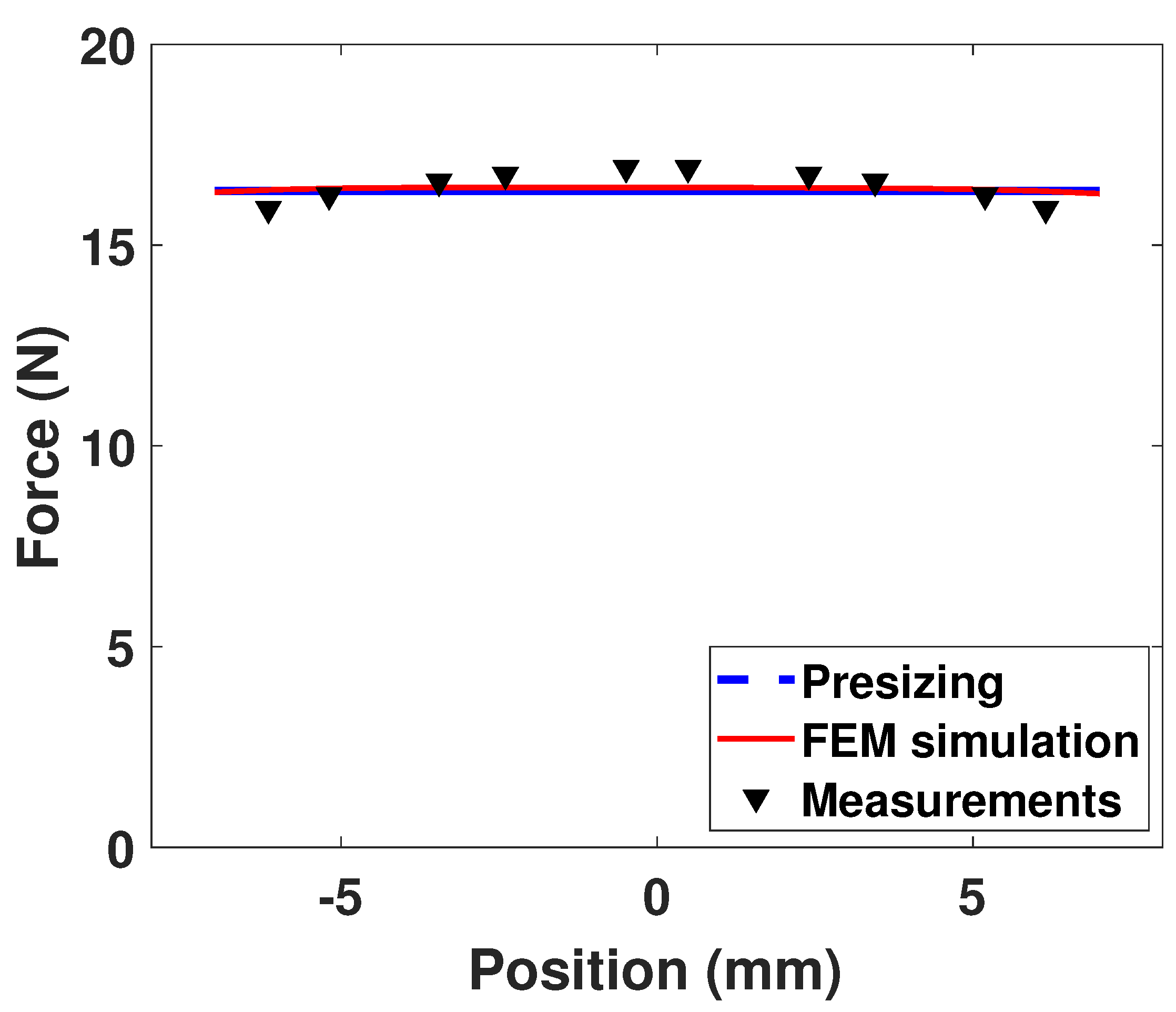
Figure 16 shows the force-position relation, for a constant current i = 0.5 (A). Due to the PMs edge effects, the force reduction at the maximal and minimal key positions is about 6% of the maximum force.
3.2. Dynamic Validation
In a first validation step, a simple dynamic model of a key connected to a spring—i.e., no piano action—is used in the prototype. When the key reaches a certain position, the spring is virtually disconnected to simulate a kind of escapement mechanism.
Manually imposed key position is shown in
Figure 17. A corresponding proportional force, depicted in blue in
Figure 18, is applied by the actuator, until the escapement.
The actual coil current was measured by an external sensor, from which we can compute through (
5) the actuator force, called
in
Figure 18. The measured force developed by the actuator follows the desired
curve with small differences during transient states and peaks.
In
Figure 18 around 4.5 (s) and 6.2 (s),
shows two peaks while the
only show one. This difference is due to the contribution of the coil dynamics because the latter has a non-negligible vertical acceleration
at these times. Referring to Equation (
8), the coil dynamics
(
+
g) is subtracted from
to get
. Therefore, the two forces are obviously different but this does not influence the output force
, given that the key is physically present in the prototype and that it applies its own dynamics.
The actuator is open-loop feed-forward controlled: a current is applied in the coil thanks to a Pulse Width Modulation (PWM) approach on the voltage. The force is proportional to the current as in Equation (
5). A closed-loop controller could be considered, although it could affect the system reactivity and the real-time computation.
The reference voltage
is the application of Equation (
4):
where
=
is the reference current flowing through the coil and
is the coil filtered velocity.
As requested during the optimisation of
Section 2.5.1, the actuator is energy efficient: the maximum current density is low, 3.19 (A/mm
2) during this actuator dynamic validation. The corresponding mean power due to Joule losses
is 0.99 (W), which will not overheat the coil. It confirms the first simulated results illustrated in
Figure 14.
3.3. Validation with the Piano Action Model
To validate the haptic feedback, the piano action model of
Section 2.2 is used in the prototype, as explained in
Section 2.1. This double escapement model is computed in real time in the embedded controller.
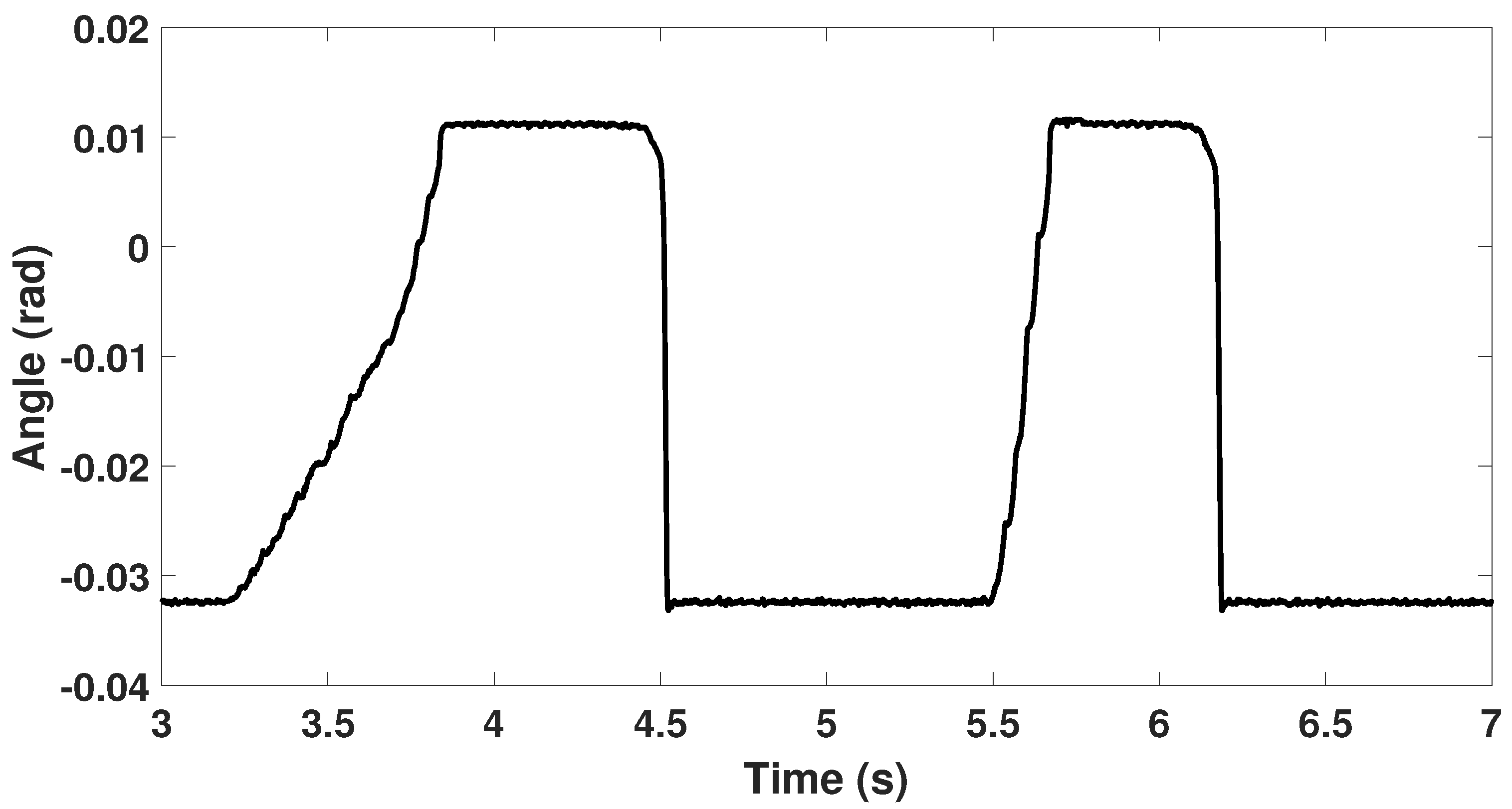
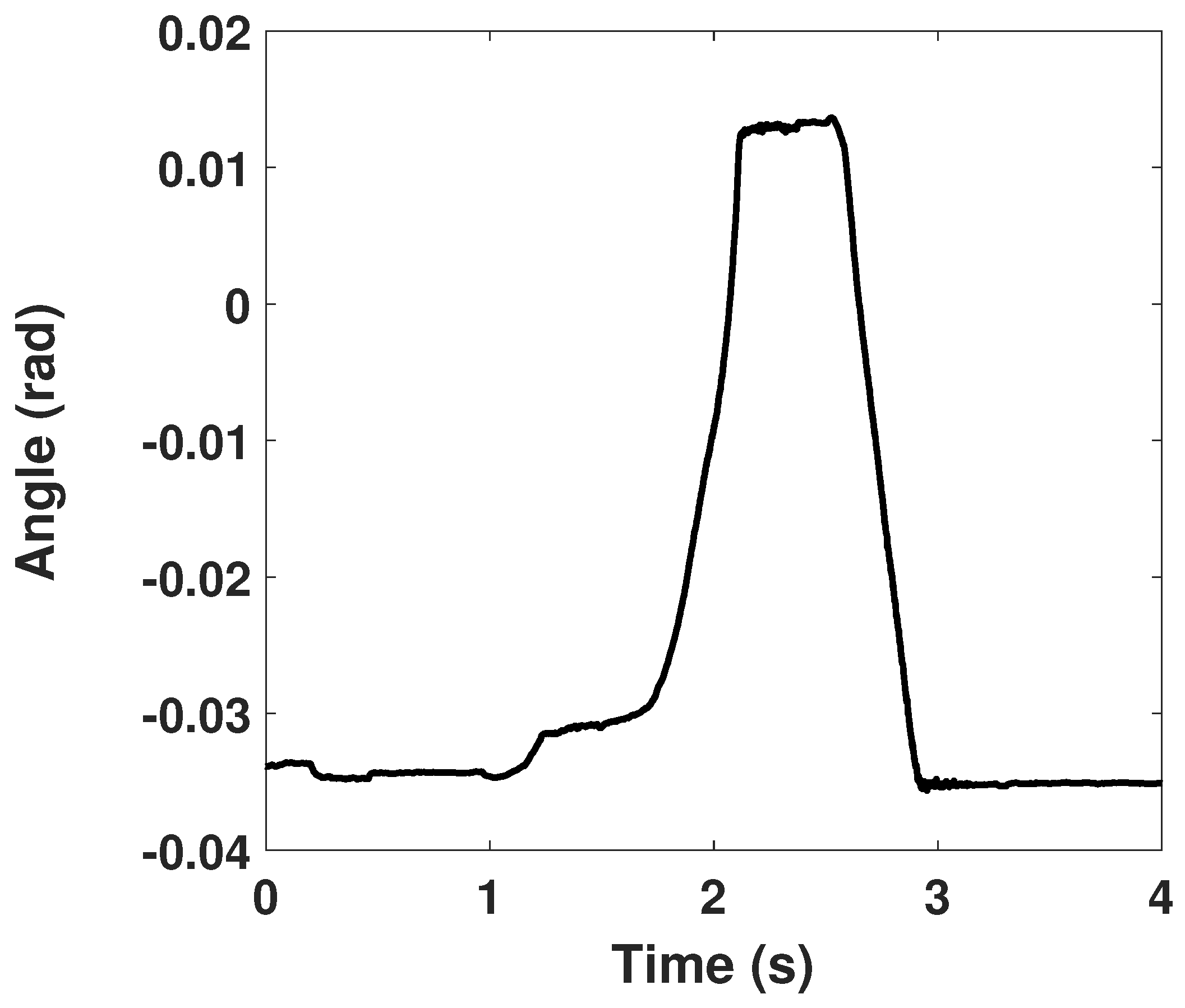
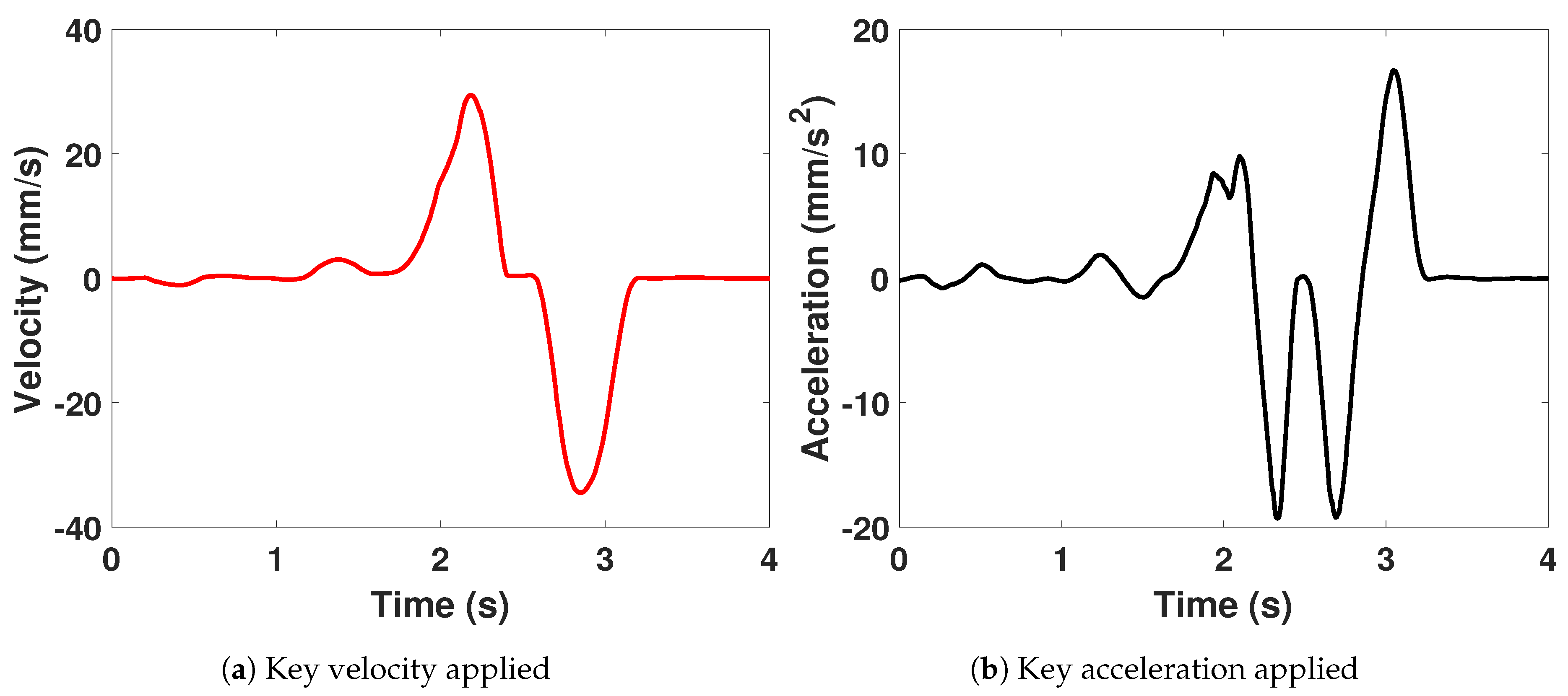
Figure 19 and
Figure 20a,b show respectively the position, velocity and acceleration of the key applied manually during the experiment. Key is fully pressed and released, at low speed of maximum 0.03 (m/s).
As in
Section 3.2, the actuator force
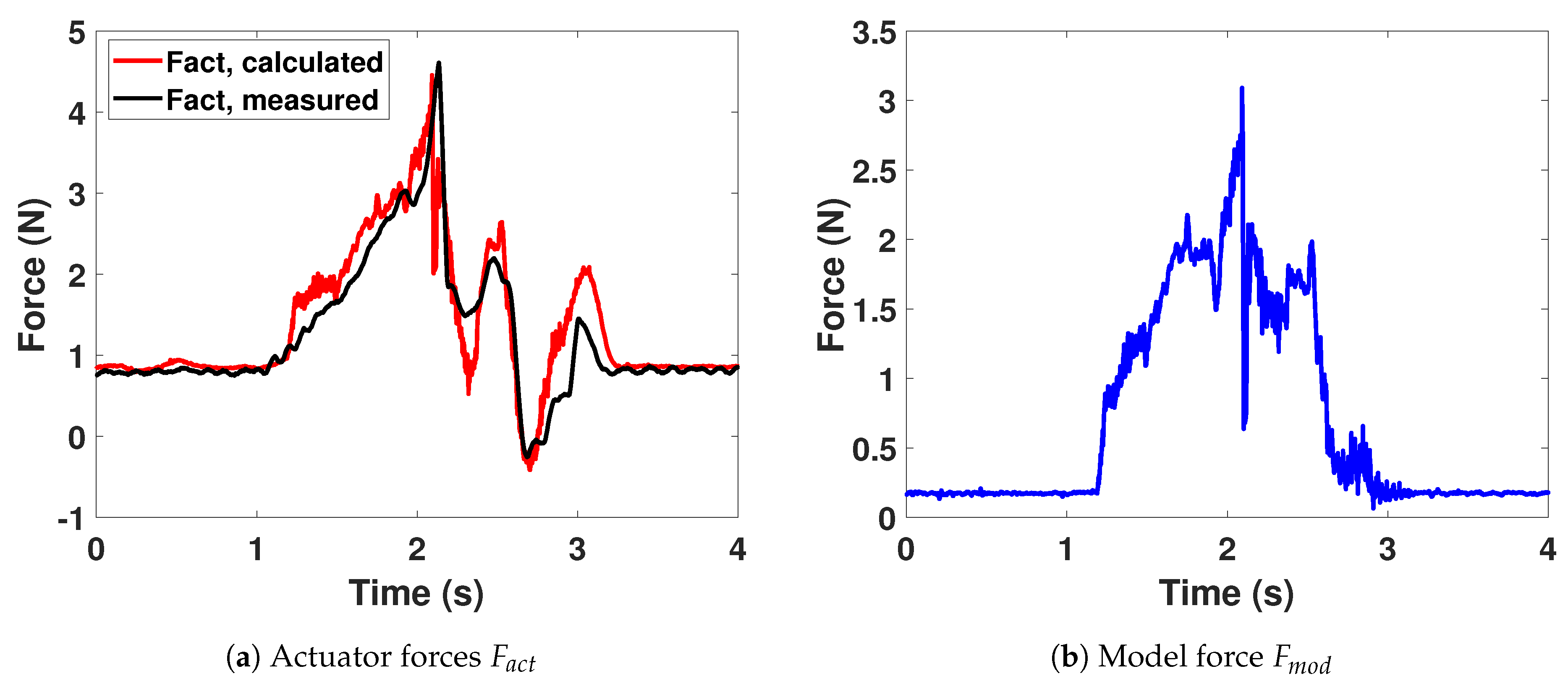
is estimated by an external coil current measurement. In
Figure 21a, the measured force
follows the
curve with small differences during transient states and peaks.
is calculated from (
5) with the desired current in the coil. The two curves should be identical, apart from the measurement errors. This results would suggest that a parameter of the actuator is imperfectly computed, which induces a difference in the coil current and thus in the output force. An other possibility is that the coil velocity is not perfectly estimated. This would influence the back-emf term
of (
9) and induce errors in the output force.
Figure 21b shows the corresponding
that is quite different from the
. Indeed, for this experiment, the coil acceleration of
Figure 20b is non negligible and impact the output force through (
8).
As one can observe, the model force is quite noisy and contains high frequencies. These are mainly due to the multibody model itself, which contains stiff components and intermittent contacts with changing states. The model dynamics has still to be experimentally characterized and the force compared to the force acting inside a real piano action.
3.4. Haptic Force Validation
The force felt by the pianist is
of
Figure 2, which depends of course of
and
but also on the physical components of the prototype. To characterize
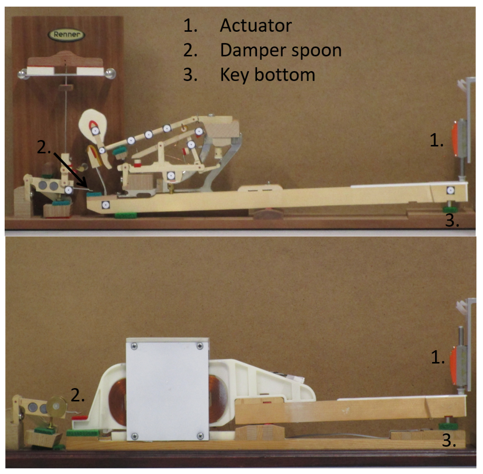
, an external actuator (Faulhaber LM1247) has been used to apply the same position-driven profile that corresponds to one full key dip at 0.01 (m/s). The
force can be deduced from the external actuator current measurement on both the Renner
® demonstrator and the prototype, see
Figure 22.
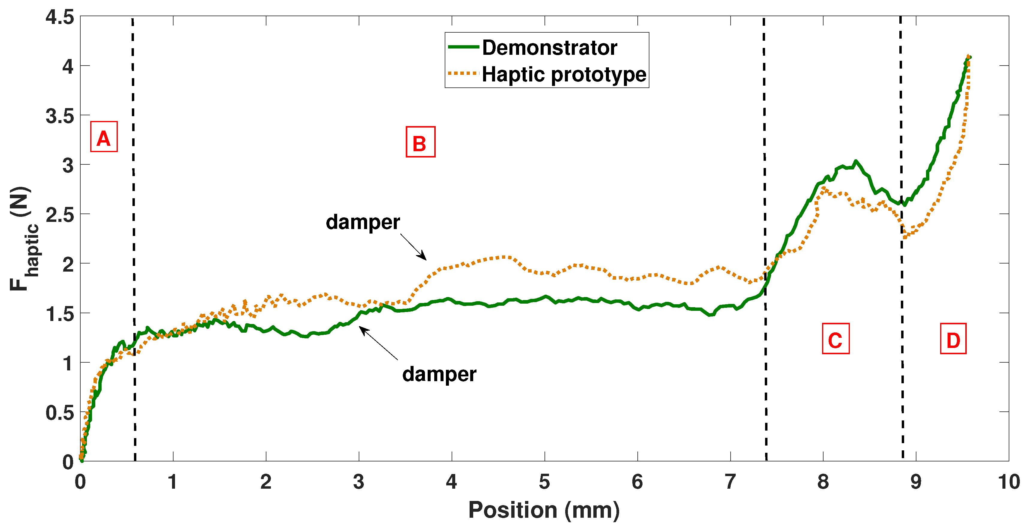
The result in
Figure 23 is central as it shows the haptic force at the key tip versus key tip vertical position. Position zero refers to a key at rest and position 9.5 (mm) to a fully pressed, as suggested in [
7]. From left to right: Phase A is the setting in motion of the action; Phase B corresponds to the upward movement of the action, while the hammer is getting closer to the string; The escapement occurs in Phase C, where a harsh point takes place, with an increased force until the hammer roller escapes from the jack; The key bottom contact appears in phase D with an increasing force.
The two profiles of
Figure 23 show similar behaviors, which is particularly encouraging. Most of the differences are due to the physical components that differ between the prototype and the Renner
® demonstrator. The contact between the key and the damper spoon is triggered—phase B—at a slightly shifted position, 3 (mm) instead of 4 (mm). The key bottom contact—phase D—is also different due to the fact that the green felt below the key, see
Figure 22, is a little bit abraded in the prototype versus the Renner
® demonstrator one.
The small difference in the force amplitude between 4 and 7 (mm)—phase B—and during escapement—phase C—is due to the force computed by the multibody model whose all parameters have not been experimentally characterized yet.
Despite theses differences,
Figure 23 shows that the prototype designed throughout this paper is able to reproduce the
force quite faithfully, i.e., the
touch of a grand piano.
4. Discussion
A piano action is a complex multibody system which is composed of many different elements made of wood, felt, leather, metal and where intermittent contacts take place (e.g., hammer escapement). The interaction between the parts and with the external world (string, stops,...) delivers at the key tip a very specific feeling and haptic rendering to the finger that strongly participates to the touch. The latter plays a crucial sensory role for pianists. The virtual restitution of this mechanical touch is the aim of the developed haptic system.
To offer this sensory information, present-day digital keyboards offer the possibility to nuance the sound and feel a certain feedback via a simplified passive mechanism. If their keyboard offers the possibility to tune the sound through their haptic response, from the sensory point of view, the result is far from reliably reproducing the touch of the actions equipping traditional acoustic pianos.
Even with complex mechanical systems, current passive solutions can only globally reproduce the inertia and stiffness effects, but miss some fundamental haptic feelings related to the escapement and the repetition mechanisms. For example, just before hitting the string and producing the sound, the hammer escapes suddenly from the action via the so-called escapement mechanism. While pressing the key of an acoustic grand piano, experienced pianists are able to detect the escapement re-triggering necessary to provoke a fast note repetition. As discussed in [
25], the haptic feedback corresponding to the key harsh points induced by the escapement is of prime interest to them.
Furthermore, an important aspect relates to the possibility to tune the action parameters, as a piano maker should do, at the pianists’ convenience and, ultimately, to switch between different types of actions at a glance, on the same keyboard.
Last but not least, the synchronization of the “virtual action–string” interactions with a sound model constitutes obviously a longer-term perspective that a research work should investigate in the future, by taking advantage of the real-time multibody model, particularly in terms of force amplitude triggering and duration.
Haptic devices interact with the human body through the complex human somatosensory system [
26]. Both force feedback and tactile sensation are felt by the contact of the skin with objects. In this work, the tactile information—i.e., the texture and mass properties—are preserved as the key characteristics remains identical to the acoustic piano one.
The force feedback of the haptic device could be seen as an equivalent stiffness-viscosity-type force that can rapidly change with time. In fact, more generally, and in a more accurate way, the multibody model computes a reaction force that depends on the key position and the key velocity, but also on the action internal dynamics, which involves frictional contacts between bodies.
The mass and inertia of the key remain close to the real one, see
Section 3.1 and
Table 2. In other words, from a sensory point of view, the pianist sees and feels the same key at the end of his finger, as that of a real acoustic piano.
The simple but efficient linear regression filtering approach applied to filter the noise in the key kinematics produces profiles are reasonably smooth, even though this part of the study could be enhanced. Additional works actually deserves to be carried out in the next future to select the best filters to be used in real time inside a haptic device such as ours, for example using a Kalman filtering technique, as suggested in [
27] for a linear actuator.
Finally, the prototype should be validated not only with a force-feedback approach as proposed in this paper but also on the basis of real pianists’ feelings. To achieve that, a multi-key prototype will be built on the basis of our current key design so that pianists may test our haptic device and play in an environment close to the real playing conditions.
5. Conclusions
For the pianist playing on an acoustic piano, the touch gives useful information that, along with the sound feedback, allows him to nuance his play. In this paper, the design and validation of an active haptic prototype is presented, which aims at reproducing the touch of an grand piano. A multibody model of the double escapement action is computed in real time in the device, the goal being to upgrade the force feedback response of digital keyboards.
In combination with sound feedback, the touch of a grand piano gives useful information for the pianist to nuance his play. However, current digital keyboard are equipped with passive mechanical systems whose dynamics fails to imitate the action feeling of the acoustic pianos.
To improve the sensation of the pianist, the force feedback of digital keyboard can be upgraded with a haptic force-feedback device, as suggested in this work. Instead of the mechanism, a real-time multibody model enables the actuator to apply the same dynamic force on the key to provide the same touch feeling as in an acoustic piano.
In the haptic prototype designed, the linear electromechanical actuator is based on the voice coil principle contained within one-key width. A specific care has been taken in the actuator design process, with three steps: presizing based on dimensional optimisation; electromechanical design verification by FEM techniques; validation by simulations and measurements.
As the optimisation aimed at reducing the losses, the mean power dissipated stays below 1 (W) even for a very demanding force profile, which will not cause overheating risks on the coil. A bi-objective optimisation could enhance the design by optimising the force-density along with minimizing the losses. Developing a thermal model of the actuator would also enhance the design process.
In the case of a force density optimisation, inserting a spring-based element between the key and its frame could alleviate the force to be produced. For instance, the spring could balance for the action equilibrium weight. Yet, the spring will introduce an oscillatory behavior [
28] that, if not correctly taken into account in the model, could regrettably influence the touch.
Thanks to the proposed design, (i) the properties of the key (texture, mass, center of mass, inertia, kinematics) is the same as its acoustic equivalent, which is a unique attribute of this work with respect to the current haptic keyboard state-of-the-art; (ii) furthermore, the multibody approach allows, in addition to mimic the dynamics of a real action, to (de)regulate it or even to swap between different types of action. (iii) moreover, the homemade actuator is experimentally validated and answers some challenging problem requirements, especially in terms of action dynamics and speed. The custom design allows fortissimo nuances, with peak forces up to 50 (N) in less than 20 (ms).
Increasingly accepted by pianists, digital pianos would greatly benefit from these three advantages. Their keyboards could produce the same touch as their acoustic equivalent. The multibody model could be swapped between, for example, the grand and the upright piano, so that the pianist can experience both sensations with only one keyboard. The multibody approach and the real-time capabilities of our models make this possible. The homemade actuator is easy to fabricate and to assemble for several consecutive keys and aims at reproducing realistic active forces that current digital keyboard are unable to generate.
Moreover, proposing a haptic device in which a multibody model is computed in real time could embrace multiple other applications [
29,
30,
31,
32,
33]. That being said, dealing with a complex dynamical model such as that of a piano action within a haptic keyboard represents a challenging and concrete application of this multibody-based approach.
Results with both a simplified model and a full double escapement piano action model illustrate the functioning of the haptic feedback. Actuator force follows the required dynamics for a manually applied kinematics. Besides, a validation with an external actuator shows that the prototype reproduces a haptic force felt at the pianist’s finger that is close to the force feedback a of grand piano action.
In the future, the multibody model of
Section 2.2 will be dynamically validated with additional experiments on the mechanism of
Figure 1. Then, the design of a multi-key prototype will allow carrying out experiments with pianists to validate the proposed concept in terms of
touch and playing comfort.


