1. Introduction
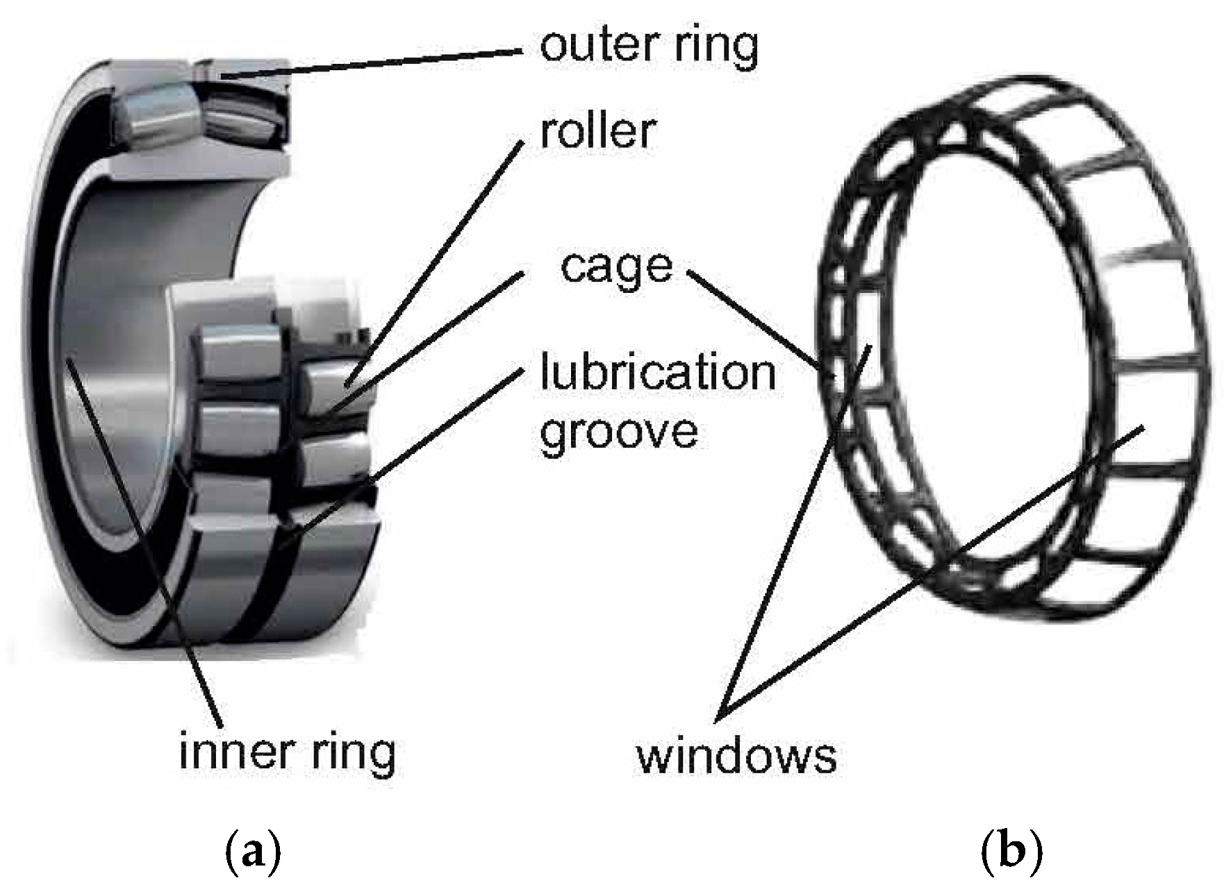
The rolling bearings are machine elements usually intended to support parts found in a rotation movement. Essentially, they include rolling elements and rings. To separate the rolling elements, bearing cages could be used, as sometimes sealing elements are provided to prevent the penetration of foreign objects or substances between bearing elements found in a relative movement to one another.
A category of roller bearings that are used in difficult service conditions, when there is the necessity of compensating the eventual deviations of the coaxiality of supporting bearings or the shaft bending, are the double row tapered roller bearings (
Figure 1a). These roller bearings are characterized by a certain self-regulation on the raceway of the outer ring.
The bearing cages presented in the bearings have generally the role of preventing the contact between rolling elements (rolls or balls). There are various methods of manufacturing the bearing cages, considering their shapes and materials. Thus, for example, in the case of cylindrical rolls, the bearing cages could be achieved essentially by successive processes of drawing, perforating the central hole, and cutting the windows. As workpieces, metallic plates that have circular shapes could be taken into consideration before drawing.
The main requirements for bearing cages refer to their accuracy, their surface roughness, and material resistance to wear processes.
If the cage machining accuracy is analyzed, in addition to the accuracy of the overall dimensions, the precision of the dimensions corresponding to the windows in which the rolling elements could be placed is important. The concept of dimensional precision refers to the deviation of the real dimensions from their nominal values.
Over the years, the results of certain research concerning the accuracy and the surface state of bearing cages or generally of the windows obtained in sheet type workpieces by forming methods were published.
Thus, Kibe et al. considered that the general position of the punch in the die could exert a significant influence on the machining accuracy in the case of shearing processes [
1]. They proposed a method that was able to increase the precision of measuring and adjusting the position of the punching tool, especially when processing metallic thin sheets. The experiments were achieved on workpieces made of phosphor bronze and aluminum that had a thickness of 0.2 mm. The researchers highlighted the influence exerted by the clearance between punch and die on the machining accuracy, taking into consideration the shape of the cross-section and the diameter of the hole obtained by punching.
Subsequently, Kibe and Mitsui investigated the influence exerted by the misalignment of the punch and die positions on the cross-section diameter of the hole and on the out of the roundness in the case of punching applied to workpieces made of phosphor bronze [
2].
Istiawan and Mahardika studied the influence exerted by the clearance and the punch speed on the surface quality evaluated by means of burnish area, fracture, and burr zone, in the case of punching a hole with the diameter of 800 µm in a workpiece with a thickness of 300 µm [
3]. They noticed the low influence exerted by the punch speed on the surface quality.
Ardeshana and Mehta took into consideration the problem of designing a punch and a die for manufacturing of a bearing cage specific to a taper roller bearing [
4]. They considered that the simultaneous cutting of all the windows in the bearing cage could contribute significantly to the decrease of the production time, and thus to the increase of the productivity.
Zhao et al. considered that an improvement of the precision manufacturing of bearing cages by the stamping process could be possible by using the reliability theory to adequately establish the thickness of the plate used as the workpiece in the process of the manufacture of the bearing cage [
5]. They modeled the behavior of the bearing cage during the punching process by using the ANSYS finite element analysis.
Various solutions were also considered in patents that referred to the producing windows in roller bearings cages by distinct manufacturing processes [
6,
7,
8,
9,
10]. Within these patents, only the processes and equipment for obtaining windows in bearing cages were discussed, without offering details about the dimensional precision of the cages’ windows that were obtainable by such manufacturing processes. Even the roller bearings are not complex systems; they could be incorporated in such systems, and principles corresponding to the mechanical systems could be taken into consideration when analyzing the roller bearing and its manufacture [
11,
12,
13,
14,
15].
The main aim of the research presented in this work was to highlight the influence exerted by the workpiece thickness, punch work stroke, side clearance, and axial clearance between punch and die on the precision of the main dimensions of the windows that exist in the bearings cages in the case of the double row tapered roller bearings. Empirical mathematical models that were able to offer information concerning the intensity of the influences of the abovementioned forming process input factors on three main dimensions of the bearing cage windows were determined.
2. Theoretical Analysis
In order to achieve the windows in the bearing cage from
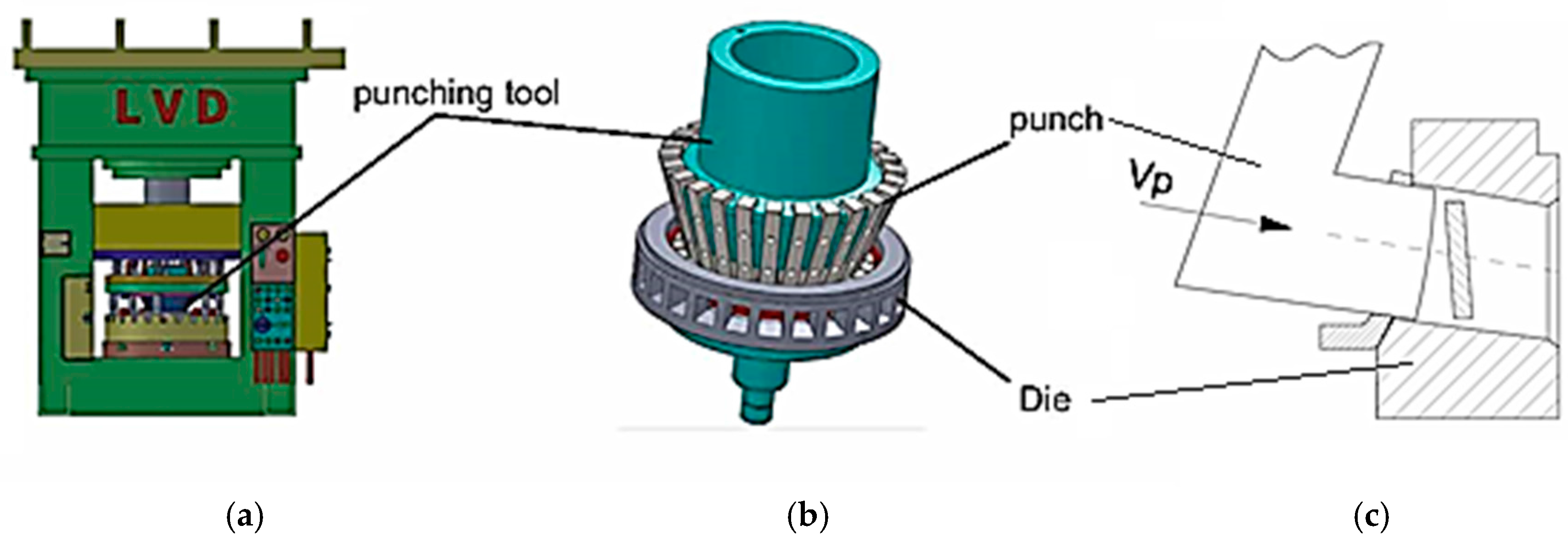
Figure 1b, a stamping process is applied. On could consider that the stamping process develops on hydraulic pressing equipment (
Figure 2a) and using a mold that supposes the axial movement of a central conical mandrel. Due to this movement and to the conical shape of the central conical mandrel, the punches that have an approximate L shape are forced to radially move, materializing the process of window cutting (
Figure 2b,c). Since there is a number of punches that is equal to the number of windows that exist in the bearing cage, at a single work stroke of the central conical mandrel, all of the windows are cut.
In
Figure 3, the shape and the main dimensions specific to a window that exists in the bearing cage could be seen. The main dimensions of the window are the window width
Ww, the window height
Hw, and the distance
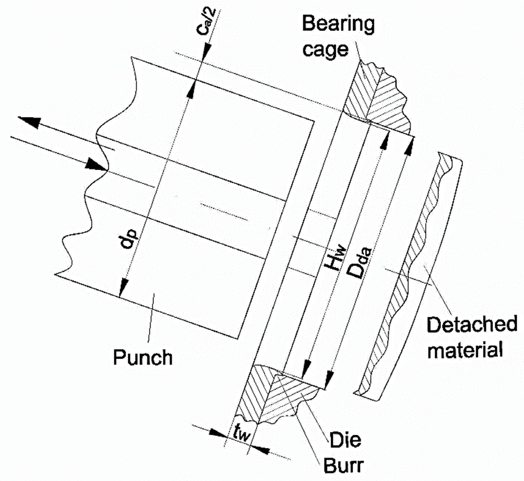
Drt between the retention thresholds belonging to the same window. As a consequence of the punch movement, a part of the workpiece material is detached, and a hole is thus generated in the bearing cage (
Figure 4).
During the rolling bearing service, especially the window height Hw, and the distance Drt between retention thresholds are important, since they determine the clearance between the bearing rolls and the bearing cage. These dimensions are determined during the rolling bearing design activity by taking into consideration the recommended or imposed values for the length and the maximum diameter of the bullet roll, the axial, the side, and the tangential clearance between the roll and the bearing cage.
There are many factors that are able to exert influence on the precision of the dimensions
Hw,
Ww, and
Drt during the process of window cutting in accordance with the machining scheme presented in
Figure 2b.
The factors that are able to influence the precision of the window cutting in the bearing cage could be grouped in the following way:
Geometry of punch and die active zones;
Size of clearance between punch and die;
Length of punch work stroke and cutting speed;
Certain physical–mechanical properties of workpiece material (friction coefficient, shear resistance, hardness, yield strength, formability, etc.);
Level of wear that characterizes the active zones of the punch and die, etc.
The clearance between the punch and the die could be determined as a half of the difference between the dimension of the hole that exists in the die and the conjugate dimension of the punch, both in cross-sections. For example, in the case of windows height
Hw, the relation for determining the axial clearance
ca (clearance measured along the roller axis) is the following:
in which
Dda is the axial dimension of the cross section of the hole existing in the die, and
dpa is the adequate dimension of the punch cross section.
As hypothesized, one can consider that the increase of the clearance between the active zones of punches and die and wear level of these main components will determine the decrease of the cutting process accuracy and of the burr height.
On could suppose a monotone influence exerted by the clearance
c between punch and die, by the workpiece thickness
tw and by the length of punch work stroke
ls on the accuracy of the dimensions that characterize the window cut in the bearing cage. Accepting such a hypothesis, one could consider that a power type equation could be able to highlight the intensity of the influence exerted by the workpiece thickness
tw, the length
ls of work stroke, the side clearance
cs, and axial clearance
ca on the deviation
ΔDi of the investigated dimension
Di from its nominal value:
in which the coefficient
C0 and the exponents
C1,
C2,
C3, and
C4 could be experimentally determined. The values of the exponents
C1,
C2,
C3, and
C4 will characterize the intensity of the influence exerted by the considered process input factors on the cutting accuracy of the bearing cage window.
3. Materials and Methods
In order to test the hypotheses concerning the influence exerted by the considered input factors of the window cutting process on window cutting accuracy, experimental research was designed and carried out [
16,
17].
The experiments were made on the LVD 600 type hydraulic pressing equipment (
Figure 2a). The punch and the die correspond to the schematic representation from
Figure 2b.
As material of the bearing cage, the steel DD13 (SR EN 10111: 2008) was considered. In the chemical composition of this steel, there are the following main components: 0.034% C, 0.015% Si, 0.25% Mn, 0.02% P, 0.0130% S, etc. The tensile strength of this steel is about 400 MPa.
The possibility was considered of developing an experimental research in which the results could be mathematically processed by means of software based on the method of last squares so that, finally, empirical mathematical models could be determined and analyzed. These empirical mathematical models have to highlight the intensity of the influence exerted by considered process input factors on the sizes of the parameters of technological interest, from the point of view of cutting accuracy.
Regarding cutting process input factors (independent variables), the followings were considered: the workpiece thickness tw, the length of the punch work stroke ls, the side clearance cs (clearance measured in a plane perpendicular on the axis of the virtual roller), and the axial clearance ca between the punch and die.
The values of the process input factors tw, ls, cl, and ca, and of the output parameters (deviation ΔHw of the window height Hw, deviation ΔWw of the window width Ww, and deviation ΔDrt of the distance Drt between the cage retainer thresholds, were measured using the MarSurf XC 2 contour measuring station. The station guide deviation is lower than 1 µm/120 mm.
As experimental result, the deviations of the measured dimensions from their nominal values were considered.
The experimental conditions and results were presented in
Table 1. In the column nos. 2, 3, 4, and 5, the values of the process input factors were included, while in the columns nos. 6, 7, and 8, the sizes of the process output parameters were mentioned.
4. Results
The experimental results were mathematically processed by means of software based on the use of the method of least squares [
18]. The software allows for the consideration of five distinct mathematical empirical models. The adequacy of these empirical models for the experimental results could be estimated by means of the so-called Gauss’s criterion. The value of the Gauss’s criterion could be determined as a sum of squares of the differences between the measured values and the values determined using the empirical mathematical models, for the same experimental points.
As results of experimental mathematical processing, the following mathematical empirical relations were determined:
in this case the Gauss’s criterion has the value
SG = 0.0008970296,
for which the Gauss’s criterion has the value
SG=0.00000848762, and
the Gauss’s criterion has the value
SG = 0.000007217791.
On the base of the empirical mathematical models expressed by the Equations (3)–(5), the graphical representations from
Figure 5,
Figure 6,
Figure 7 and
Figure 8 were elaborated.
5. Discussion
The analysis of the empirical mathematical models (3)–(5), and of the graphical representations from
Figure 5,
Figure 6,
Figure 7 and
Figure 8, facilitated the formulation of some general remarks concerning the influence exerted by the process input factors on the dimensional precision of windows cut in bearing cages.
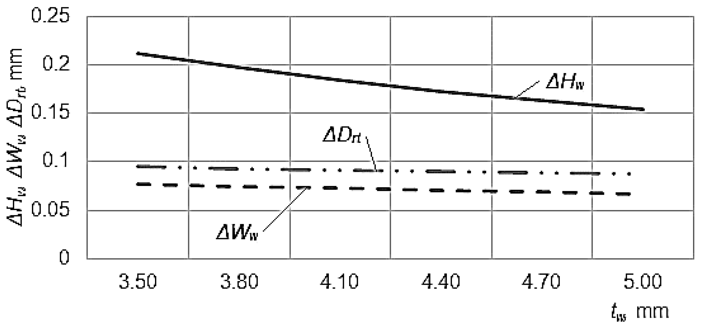
Thus, one can notice that the increase of the workpiece thickness
tw determines an increase of the machining accuracy (a diminishing of the deviations
ΔHw,
ΔWw, and
ΔDrt,
Figure 5), and this could be justified by the increase of the workpiece rigidity, which has as an effect a more precise cutting of the windows. In all the three mathematical empirical models, the exponents attached to the factor
tw have a negative value, and the highest influence is exerted on the deviation
ΔHw of the window height
Hw when the exponent has a maximum value.
If the influence of the work stroke length
ls is analyzed, one could notice that in all the three cases the increase of this factor value determines an increase of the deviations
ΔHw,
ΔWw, and
ΔDrt (a decrease of the machining precision,
Figure 6). The fact could be justified by the longer contact between the workpiece and the cutting punch, which could contribute to a supplementary material removal from the workpiece, inclusively by developing an intense friction phenomenon. The maximum influence is exerted on the deviation
ΔHw of the window height, this meaning that the exponent attached to the factor
ls has the maximum value in the mathematical empirical model that corresponds to the deviation
ΔHw of the window height.
As expected, the increase of the side clearance
cs determines a decrease of the machining precision in the case of the deviations
ΔHw,
ΔWw (
Figure 7), when the exponents attached to the factor
cs has values higher than 3. Indeed, the increase of the side clearance
cs could change the behavior of the workpiece material during the cutting process, and this could determine an increase of the deviations
ΔHw and
ΔWw. In the case of the of the deviation
ΔDrt of the distance
Drt between the retention thresholds, the influence is practically insignificant, with the value of the exponent attached to the factor
cs being close to zero.
For relatively large values of the axial clearance
ca (0.51–0.58 mm), one notices that the increase of this factor leads to a decrease of the deviations
ΔHw,
ΔWw (the exponents attached to the factor
ca in the empirical mathematical models having negative values) and exerts a relatively low influence on the deviation
ΔDrt of the distance between the retention thresholds, as can be seen in
Figure 8. The strongest influence is exerted on the deviation
ΔDrt of the distance between the retention thresholds, the fact being highlighted both by the exponent attached to the factor
ca in the empirical mathematical model of
ΔDrt (Equation (5)) and by the graphical representation from
Figure 8.
6. Conclusions
The windows that exist in the bearing cage could be obtained by a forming process that involves the use of a punch and a die. Over the years, researchers have become concerned with the influence exerted by distinct factors on the machining precision that corresponds to punching processes. Only a few experimental results referred to the machining precision of the bearings cage windows. In this paper, the problem of investigating the machining precision in case of the cutting process of windows in cages for double row tapered roller bearings was addressed. The theoretical analysis highlighted that the workpiece thickness, the length of punch work stroke, and the clearance between the punch and die could be factors that are able to affect the dimensional precision of the windows cut in the bearing cage. Experimental research was developed to identify the influence exerted by the above-mentioned process input factors on the precision of some of the windows’ overall dimensions and on the so-called distance between the retention thresholds. By mathematical processing of the experimental results, power type empirical mathematical relations were determined. These empirical mathematical models and the graphical representations were analyzed to obtain information concerning the influence of some process input factors on the machining precision of obtaining certain dimensions of the cage windows. Essentially, the increase of the workpiece thickness determines the increase of the machining precision, while the increase of the punch work stroke length contributes to a decrease in the machining accuracy. The increase of the side clearance leads to an increase of the cutting deviation, and the increase of the axial clearance determines the decrease of the overall dimension deviations. In the future, there is the intention to extend the experimental research so that the empirical mathematical models will be used to optimize the punching process of window cutting in bearing cages.


