Article

Double Lighting Machine Vision System to Monitor Harvested Paddy Grain Quality during Head-Feeding Combine Harvester Operation

1
Graduate School of Agriculture, Kyoto University, Kitashirakawa-Oiwakecho, Sakyo-ku, Kyoto 606-8502, Japan
2
Department of Biological and Agricultural Engineering, Faculty of Engineering, University Putra Malaysia, 43400 Serdang, Selangor, Malaysia
3
Agricultural Research Center, Agricultural Operations Business, Yanmar Co., Ltd., 2481, Umegahara Maibara, Shiga 521-8511, Japan
4
Department of Mechanical and Biosystem Engineering, Bogor Agricultural University (IPB), Jawa Barat 16680, Indonesia
*
Author to whom correspondence should be addressed.
Machines 2015, 3(4), 352-363; https://doi.org/10.3390/machines3040352
Submission received: 9 September 2015 / Revised: 14 October 2015 / Accepted: 6 November 2015 / Published: 13 November 2015
(This article belongs to the Special Issue Agricultural Machinery)

Abstract

:
A machine vision system to evaluate harvested paddy grain quality during harvesting using double lighting was developed. The prototype consisted of a low-cost web camera and two lighting systems: a ring white LED for front lighting, and a flat dome white LED light for backlighting. Both lighting systems were arranged in a coaxial axis, making the system simple, compact and easy to handle. The aim of the system is to analyse the captured images and determine the amount of unwanted materials (rachis branch, grass and leaves, and stems) and damaged grain (brown and crack rice) present in the paddy as it is being harvested. In this paper, we introduce the first step in the development of the system: the design and selection of components to optimize the performance of the system to monitor harvested paddy grain quality. The idea would be to mount the system on top of the inlet channel of the grain tank of a combine harvester to provide real-time assessment of harvesting operational parameters.

1. Introduction

Paddy grain quality is an important parameter that is continually changing from field to consumption. More precisely, paddy grain quality can be defined in terms of the sum of all the attributes that lead to consumer product acceptability. Although this quality is often subjectively assessed by humans, including such attributes as appearance, smell, texture, and flavor, there are six main physical characteristics which objectively determine the material quality of paddy: moisture content level, grain maturity, varietal purity, present of dockage (such as straw, leaves and rachis branch), and present of discolored and cracked grains.
For these material paddy grain quality characteristics, most research has either focused on pre-harvest attributes or on post-harvest attributes, particularly the milling process. Research on pre-harvest attributes has demonstrated the significant within-field variability of paddy grain quality (protein and moisture content) [1,2,3], while in the post-harvest milling process, quality assessment has focused on physical characteristics, such as immature grain, varietal purity, and discolored grain (identification of damaged grain kernels) [4], inspecting and identifying rice varieties [5], degree of milling [6], yield prediction, and percentage of whole kernels [7], etc. To date, though, no research has been done on quality assessment of the material attributes of the paddy during harvesting. In this study, we focus on a methodology to assess, in real-time, the material quality attributes of the harvested paddy, such as dockage and cracked grain.
The rationale for this is that farmers need to monitor the harvested paddy grain and adjust their combine harvester operation settings (such as travelling speed, threshing depth, sieves, wind blower, etc.) to optimize grain yield, minimize grain damage and quality deterioration, and minimize dockage (see Table 1). Currently, in order to do this, though, they need to continually stop the harvester and inspect the harvested paddy grain in the grain tank during harvesting. Improper adjustment of operating parameters can lead to grain damage, increased grain loss, excessive unwanted material (straw, grass and etc.) and clogging [8,9]. Moreover, the farmers can only qualitatively assess the damaged grain and amount of dockage in the harvested grain, leading to inconsistent assessment, and an assessment that is highly dependent on the experience and expertise of the farmer.
Recent developments in precision and computer-assisted automated agriculture using sensors and machine vision [10] promise to help the farmer to make better management decisions. Besides the precision and efficiency offered, a machine vision system offers farmers the opportunity to build value-added characteristics and brand awareness of their product through consistency, minimizing the need for further downstream processing, and the robustness and ease of use of their product [11]. Such advantages could be obtained if the current time-consuming and inconsistent manual inspection of paddy grain quality during harvest could be replaced by a machine vision system that aids in real-time decision making for combine harvester operations.
In order to achieve this, we aim to develop a paddy grain monitoring system which can be mounted in the grain tank of a head-feeding combine harvester. The monitoring system can conduct real-time image analysis of harvested paddy when it enters the grain tank. The results of image analysis will then be used to inform the operator what parameters should be adjusted, or used as input parameters for automatic adjustment. This paper reports the first step in the development of a machine vision system to evaluate harvested paddy grain quality in a combine harvester grain tank.
Table 1. Harvesting grain conditions and necessary adjustment of the combine harvester parameters.
Type of ConditionsHarvesting Grain ConditionNecessary Adjustment of Combine Harvester Setting
Unwanted materialMany long rachis branchesIncreased travelling speed
Stronger wind blower
Narrower opening sieve
Narrower dust ejection
Large amount of grass and leavesStronger wind blower
Narrower opening sieve
Shallower threshing depth
Many stemNarrower opening sieve
Damage GrainLarge amount of brown and cracked riceDecreased travelling speed
Weaker wind blower
Wider opening sieve
To construct such a machine vision system it will be important, as a first step, to select an appropriate illumination system which optimizes the detection of damaged grain and unwanted material in the harvested grain. Moreover, the system will need to be simple, compact, and relatively low cost, as well as physically robust as it will be used in harsh field conditions. To date, most machine vision grading of agriculture products has used front lighting systems for color related information. Brosnan et al. (2004) reported that the quality of rice is based on variety of properties such as size, shape, color, chalkiness and number of broken rice kernels, color and chalkiness [11]. Shantaiya et al. (2010) used the morphological and color features to identify different varieties of rice using feed forward neural network [12]. Verma (2010) used the back propagation through time neural to sort the rice into chalky, sound, and broken kernels [13]. Yao et al. (2010) develop an inspection system of rice exterior quality (head rice rate, chalk rice, crackle rice) based on computer vision [14].
Novini (1990) reported that most illumination system arrangements could be grouped as one of the following: front lighting, back lighting, and structured lighting [15]. Normally front lighting and structured lighting gives color information, while back lighting generates instant contrast as it creates dark silhouettes against a bright background. By enhancing image contrast, a well-designed illumination system can improve accuracy and lead to successful image analysis [16]. Therefore, this paper focuses on the design and selection of lighting components, and the construction of a robust, prototype machine vision system to monitor harvested paddy grain quality with the expectation that the system will then need to be further developed to enable farmers to operate the combine harvester at full capacity and maximum efficiency through real-time measurement of and adjustments to harvesting operations.

2. The Proposed Machine Vision System for Monitoring Harvested Grain Quality

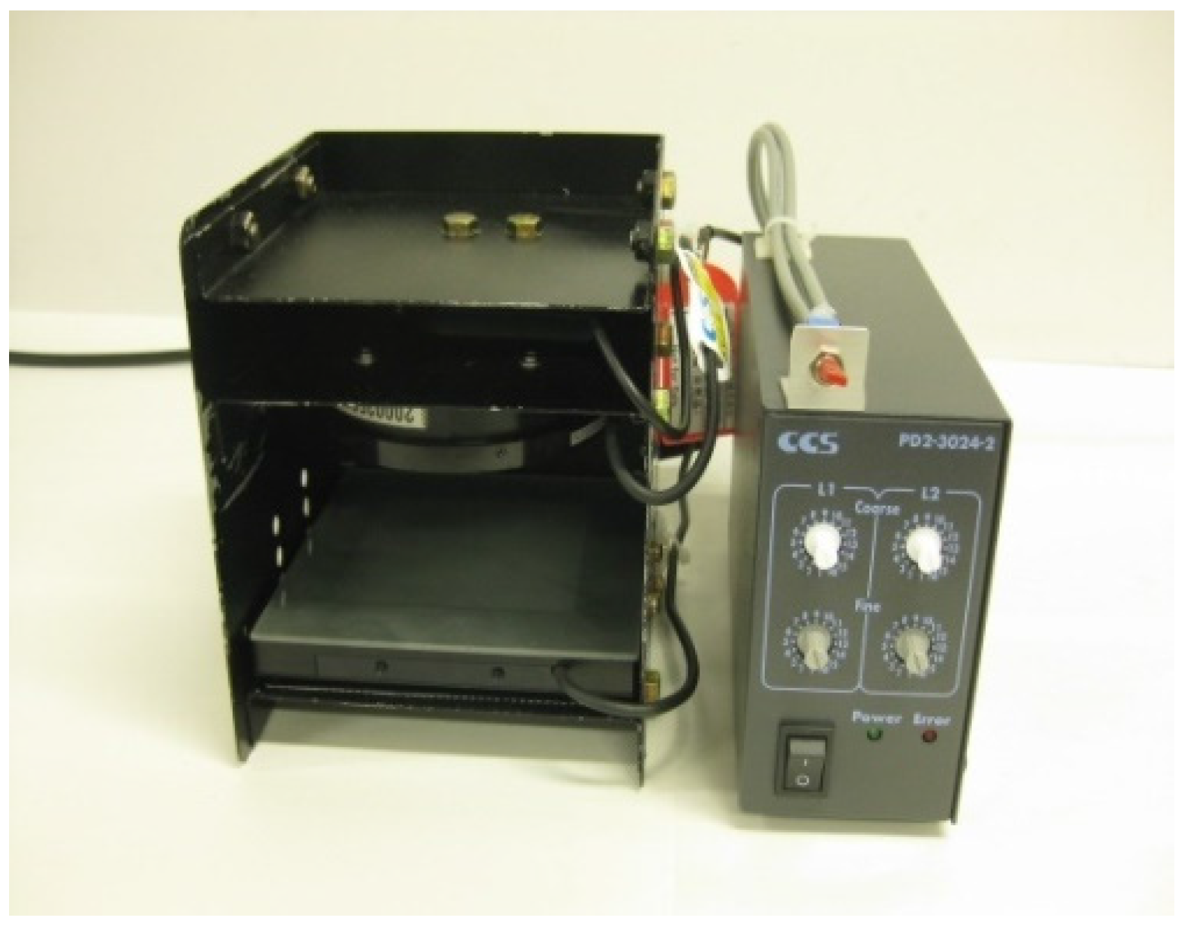
2.1. Design of Double Lighting System

In this study, a double lighting system was developed for monitoring harvested paddy grain: a frontlight system and a backlight system. Each will in turn be discussed.

2.1.1. Frontlight System

Selection of an appropriate illumination system is the most important component of the machine vision system. In terms of selection critieria, uniformity of light distribution brightness is of primary concern. The Ring-type white LED (Hayashi Watch-works Co., Ltd., type: HDR55W, Tokyo, Japan) and the Dome-type white LED (CCS Inc. Co., Ltd., type: HPD-100SW, with a temperature of 5500 K, Kyoto, Japan) illumination systems were compared using a whiteboard to evaluate their distribution brightness (Figure 1).
Figure 1. Brightness distribution by using whiteboard for different types of lighting system. (a) Ring light; (b) Dome light.
Machines 03 00352 g001
These figures show a distribution brightness in the range of 0 to 255 (from minimum to maximum pixel value) for the two lighting systems. For example, the Ring light has a maximum brightness of 152 and a minimum of 19 (Figure 1a), while the Dome light ranged from 218 to 93 (Figure 1b); there is not such a big difference between them. In order to make the light system compact and for ease of mounting in the grain tank, the Ring LED light was a better choice for the frontlight system. This is because the camera can be placed between the Ring lights and thus maintain a compact system. In addition, a Ring light is not as heavy as a Dome light.
These Ring lights are a white LED type (CCS Co., Ltd., type: LDR2-90-30SW with a temperature of 5500 K) with Polarizing (PL) filter. The Ring LED lights were set at an angle of 45° to the object plate to concentrate the light at the center of the target objects [17]. As the targeted illumination area was set at 50 mm × 50 mm, the Ring LED lights were set up at a distance of 47 mm in front of the object plate.

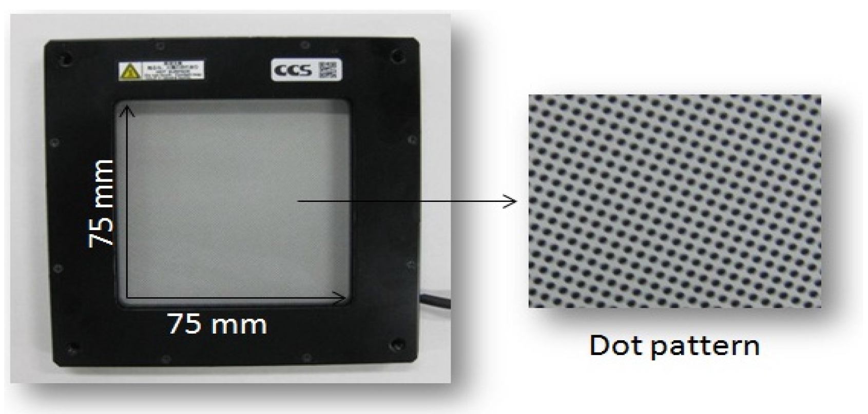
2.1.2. Backlight System

The distribution brightness on a whiteboard of a Flat dome light (CCS Inc. Co., Ltd., type: LFX2-100SW with a temperature of 6600 K) and a Coaxial light (CCS Inc. Co., Ltd., type: LFV-35SW with a temperature of 6500 K) were compared for use in a backlight system (Figure 2).
Figure 2. Brightness distribution by using whiteboard for different types of lighting system. (a) Flat dome light; (b) Coaxial light.
Machines 03 00352 g002
These figures show the distribution brightness in the range of 0 to 255 (from minimum to maximum pixel value) for the two lighting systems. For example, the Flat dome light has a maximum brightness of 226 and a minimum of 139 (Figure 2a), a small variation in in brightness denoting a relatively uniform light distribution, while the Coaxil light ranged from 195 to 83 (Figure 2b). Therefore, we chose the Flat dome light, with its more uniform light distribution, to be used in the backlight system.
Normally, a critical problem for image acquisition when using both a front and back lighting set up on the same axis with conventional (diffusion plates) and LEDs (for example: CCS Co., Ltd., type: TH-63X60SW) is that the frontlight image of the objects will be poorly contrasted from the background color; making it difficult to distinguish between the target objects and the background.
In our system, we used a square white Flat dome light unit (CCS Co., Ltd., type: LFX2-75SW with a temperature of 6600 K) with a dotted pattern for indirect backlighting to resolve this problem during frontlit image acquisition. This Flat dome LED light has dots printed on the surface of the light diffusion plate (Figure 3). The dot pattern on the surface of the light diffusion plate controls illumination diffusion and transmission [18]. It can illuminate objects with a more uniform and diffused light. Besides that, when using this Flat dome light in the backlighting system, a PL filter does not need to be used in front of the backlight system.
Figure 3. Flat dome light units (indirect lighting).
Machines 03 00352 g003
As a result, the background of a frontlight image will be dark in color and thereby ease differentiation between target objects and the background. The conventional method for taking a frontlight image is to put the sample on a black plate for high contrast between the background and objects. However, this makes it difficult to take the backlight image with the same orientation and conditions.

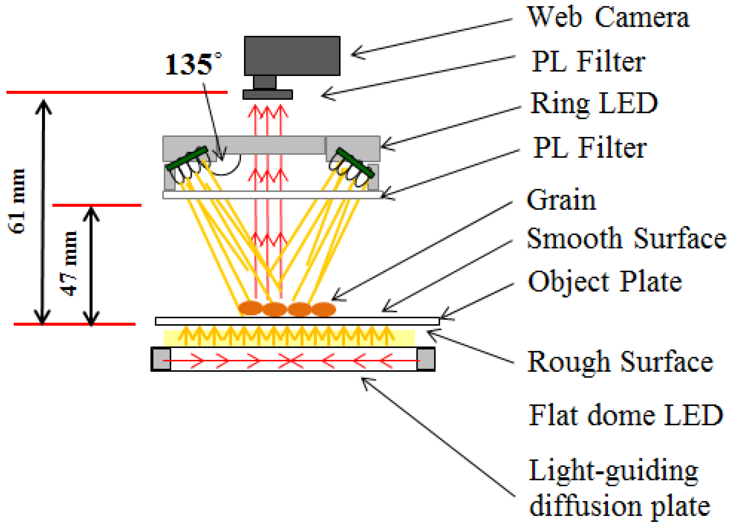
2.2. Overall Setup of Double Lighting System

2.2.1. Design of Whole System

A schematic of the proposed double lighting system is shown in Figure 4. The front and backlight systems were aligned along the same axis.
Figure 4. Layout of schematic diagram for double lighting system.
Machines 03 00352 g004
The advantage of using a double lighting system aligned along the same axis is that both frontlit and backlit images can be sequentially acquired simply by turning the backlighting off and on. Moreover the same orientation allows the system to be more compact and easily mounted in the a grain tank of a head-feeding combine harvester. This double lighting system has been patented in Japan (Patent No. 5780642) [19].
In order to acquire high-quality images, camera operating parameters were first optimized. Logicool Webcam Software version 1.1 (Logitech. Com., Romanel-sur-Morges, Switzerland) was used to adjust camera parameter settings and image capture specifications, including combinations of shutter speed and gain for ease of background removal and object classification. Once these camera parameters were optimized, images were captured at a resolution of 22 pixel/mm and a size of 1600 by 1200 pixels. The color images were 24-bit depth in the RGB color model. The data were stored in JPEG format on a computer. Control of brightness for both lighting systems was performed by a power unit (CCS Co., Ltd., type: PD2-3024-2).
The first experimental prototype was very simple and acquired sequential front- and backlight images via on-off control of the backlight source alone (Figure 5).
Figure 5. Appearance of the experimental equipment.
Machines 03 00352 g005

2.2.2. Object Plate

As shown in Figure 4, a glass plate: one side smooth and the other rough, was used as the object plate to produce a robust imaging system. The rough surface of the object plate performs the same function as a diffuser panel: distributing light uniformly. Samples were placed on the smooth surface of the object plate and the backlight LEDs attached to the rough surface side. Normally, after paddy grain has been removed from the sampling area, dust and water (for high moisture content grain) will remain on the surface of the object plate. By ensuring the surface of the sampling area on the object plate is smooth, the cleaning process should be easier and to lead to a rapid image capture of the next sample.

2.2.3. Camera

To maintain the compactness of the system and restrain costs, we used a WEB camera with a resolution of 2 megapixels (Logicool Co., Ltd., type: C905M, UXGA class) and PL filter.

3. Materials and Method

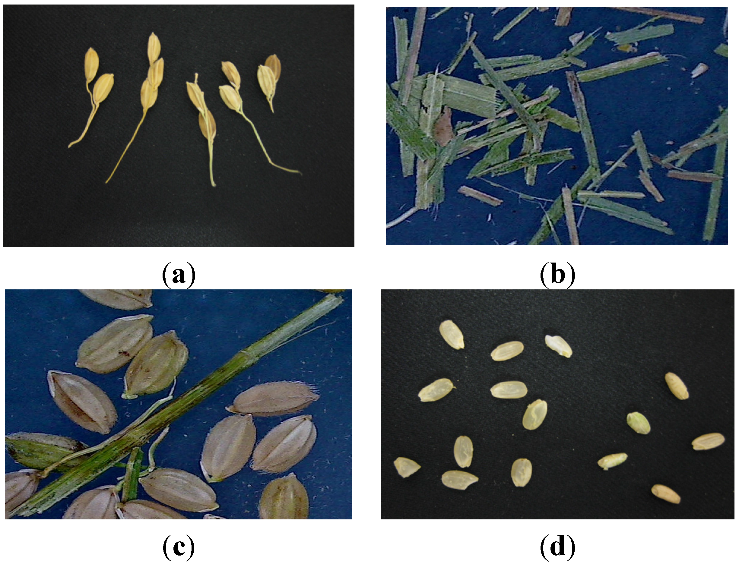
3.1. Target Materials

Paddy (Kinuhikari) harvested in mid-September 2011 in Shiga Prefecture, Japan was used as representative samples. Within this sample, 4 major objects will be detected: paddy with a long rachis branch (Figure 6a); grass (Figure 6b); stems (Figure 6c); and brown and cracked rice (Figure 6d).
Normally, the harvested grain will contain many paddy with a long rachis branch if the combine harvester is operated at too slow a travelling speed, the wind blower is too weak, the sieve opening is too wide, or dust ejection is set too wide during harvest. Too much grass in the harvested paddy grain reduces the quality of the harvested grain and can create problems later in storage. Excessive amounts of grass in the harvested paddy grain is caused by setting the wind blower too weak, the sieve opening too wide, or the threshing depth too deep during harvest. Setting the sieve opening too wide will also lead to the inclusion of too much stem material in the harvested paddy grain. Figure 6d shows the brown and crack rice. The presence of abundant brown or cracked rice indicates the combine harvester was being operated at too high a travelling speed, or the wind blower was set too strong or the sieve opening too narrow.
Figure 6. Object in harvested grains. (a) Long rachis branch; (b) grass; (c) stem; (d) brown and cracked rice.
Machines 03 00352 g006

3.2. Image Acquisition Method

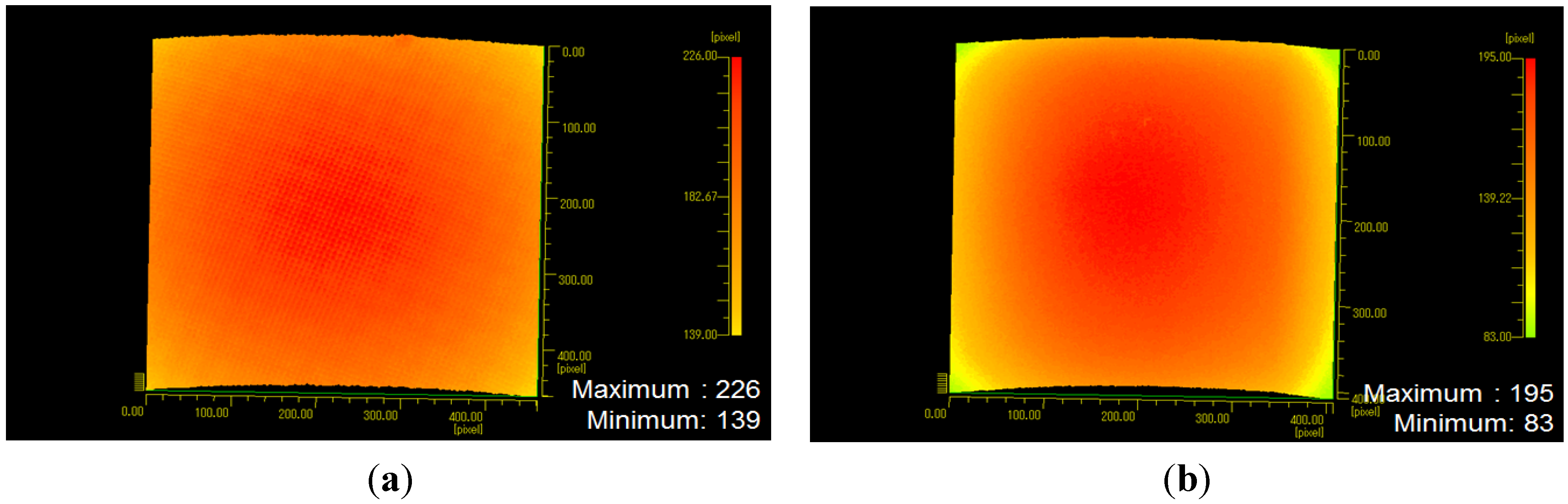
3.2.1. Frontlight System Performance

Two frontlight images of the paddy, as well as the brown and cracked rice, were captured using the frontlight system (Ring LED lights) with two different backlight systems: the dot patterned Flat dome LED light or a conventional white Flat LED light (example: CCS Co., Ltd., type: TH-63X60SW). During frontlight image capture the backlight system was turned off. The images captured by these two systems were compared for the different object types (paddy and brown rice) and background lighting systems to evaluate the performance and efficiency of the frontlight system.

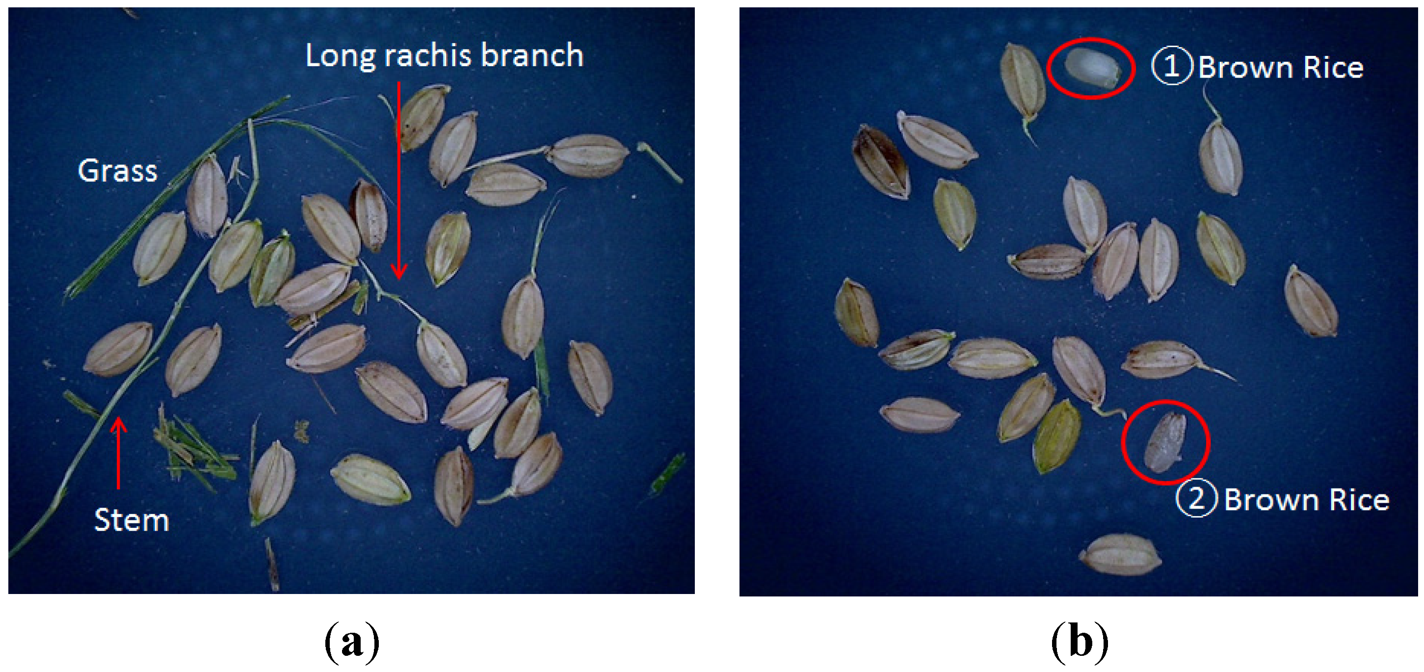
3.2.2. Comparison of Frontlight and Backlight Image Performance

From the harvested paddy grain, we obtained a sub-sample of roughly 100 g. The sampling area in our compact prototype system is small; therefore, to avoid the problems of too much overlapping and grains touching, only a 1 g sub-sample was used to acquire the image for each representative sample type: paddy, paddy with a long rachis branch, grass, stems, and brown and cracked rice. The images taken with the front and back lighting were then evaluated in terms of target material detection.

4. Results and Discussion

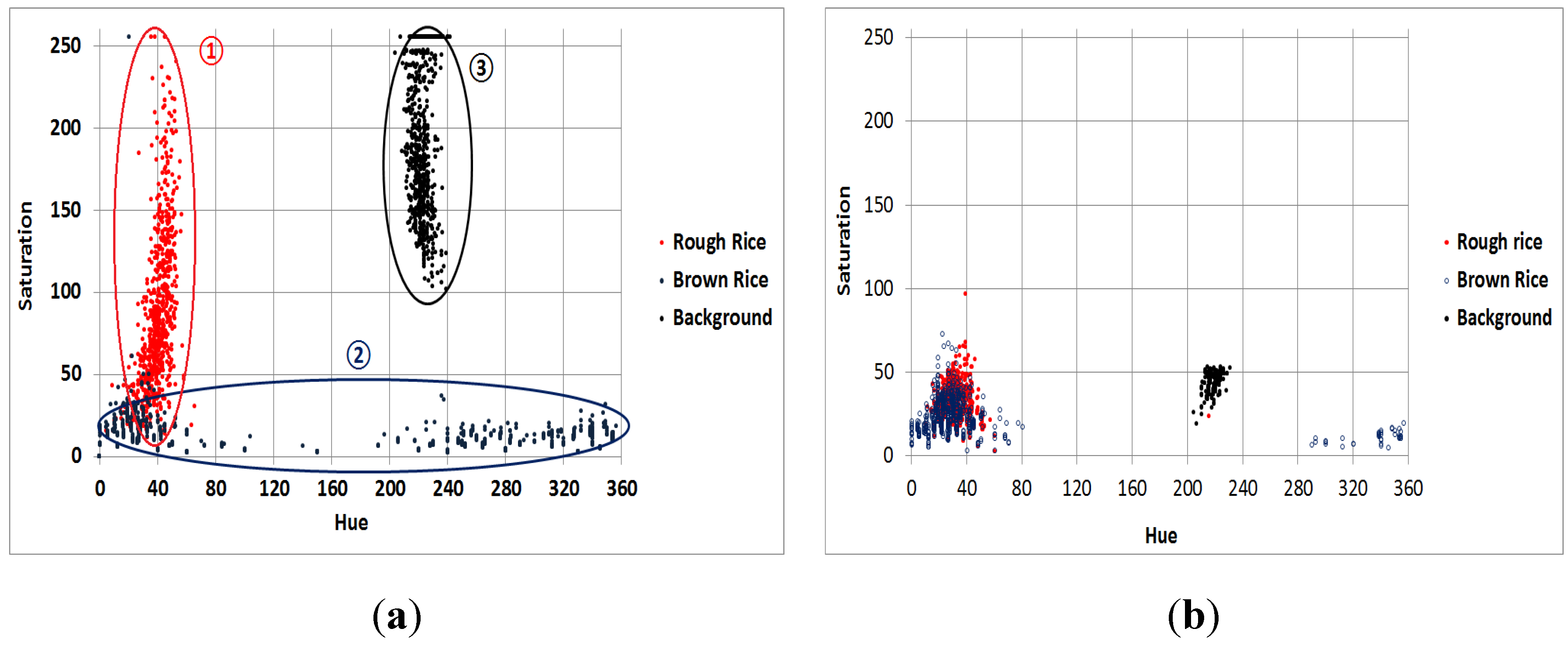
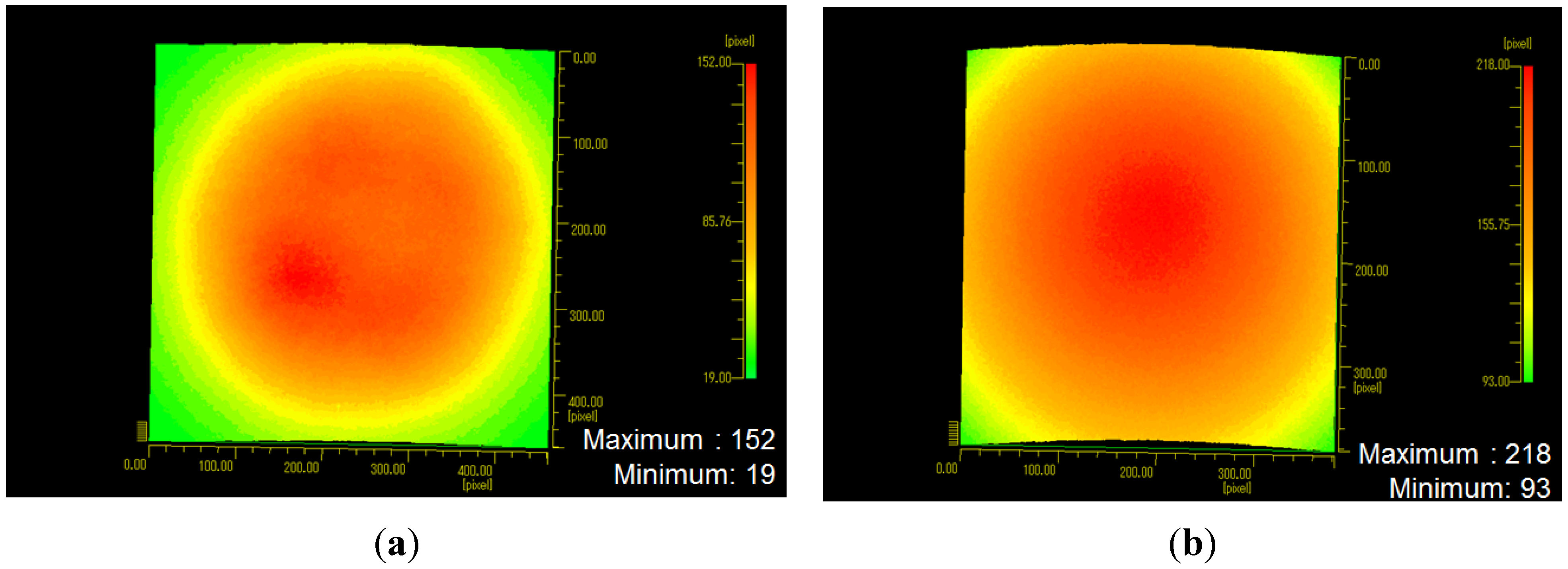
4.1. Result of Frontlight System Performance

For images taken with our double lighting system, the background is blue-black as a result of the dot-patterned Flat dome light unit in the background, while the conventional system has a whitish background (Figure 7). As a consequence, the contrast between the target objects and background is lower in the conventional system. A clear boundary threshold between for the double lighting system using the saturation and hue distribution was found between the target objects (rough and brown rice) and the background compared to that for the conventional system (Figure 8). These results confirm that using the double lighting system makes it easier to distinguish between target objects and the background.
Figure 7. Frontlight images. (a) Double lighting system; (b) conventional system.
Machines 03 00352 g007
Figure 8. Saturation and hue distribution from frontlight images captured with the (a) double lighting system and (b) conventional system.
Machines 03 00352 g008

4.2. Comparison of Frontlight and Backlight Image Performance

While color information can be used to establish a threshold for paddy, grass and stem detection, the use of color information (HSI) to distinguish brown rice is difficult (Figure 8a). This is because some HSI color components of brown rice overlap with those of paddy HSI color components. Figure 9b below shows a frontlight brown rice image with 2 types of brown rice: (1) brown rice that is almost white in color and easy to detect; and (2) brown rice color that is almost brown in color, the same color as paddy. However, by using backlight images (Figure 10b), both types of brown rice are easily detected. Therefore, for husked rice detection, it is best to use the backlight images for detection purposes.
In many cases, agricultural product grading or detection needs only one lighting system, but in the case of harvested paddy, it has been shown that two lighting systems are necessary. For paddy, rachis branch, grass and stem detection, frontlight images are necessary, while backlight images and the dark silhouettes created on the bright background can detect paddy, long rachis branch, and brown rice.
Figure 9. Image using frontlight images. (a) Long rachis branch, grass and stem; (b) 2 types of brown rice.
Machines 03 00352 g009
Figure 10. Image using backlight images. (a) Long rachis branch, grass and stem; (b) 2 types of brown rice.
Machines 03 00352 g010

5. Conclusions

In this study the principles of a new machine vision system approach to the monitoring of harvested paddy grain quality has been established. The system consists of a double lighting system (front and backlighting) set up along a coaxial axis. To maintain a compact and robust system capable of being mounted and operated in the harsh environment of a grain tank, Ring LED lights for frontlighting and Flat dome LED lights for backlighting were found to give the most uniform lighting distribution. Moreover, when using dot-patterned Flat dome LED lights for backlighting, having them turned off provides a higher-contrast background for frontlight images. Additionally, the rough surface of the botton of the object plate serves the same function as a diffuser panel, allowing for a more uniform light distribution, while the smooth front surface of the object plate aids in the cleaning process. Most importantly, this system can differentiate between four major target objects in freshly harvested paddy.
From a user and commercial perspective, the system is robust, compact, easy to assemble and low cost. As such, the proposed machine vision system shows great potential to be mounted in the grain tank of a head-feeding combine harvester for real-time monitoring of harvested paddy grain and decision support for combine harvester operations. Continued experimentation will be conducted to further enhance image processing and detection of target objects in the harvested paddy grain, such as damaged grain (husked and cracked rice) and unwanted materials (long rachis branch, grass and leaves, and stems).

Acknowledgments

The authors would like to express their gratitude to Garry Piller for his editing and proofreading of this manuscript.

Author Contributions

Naoshi Kondo (N.K) and Munenori Miyamoto (M.M) concept idea and discussion; Mahirah Jahari (M.J), Kazuya Yamamoto (K.Y), Munenori Miyamoto (M.M) and Naoshi Kondo (N.K) conceived and designed the experiments; Mahirah Jahari (M.J) and Kazuya Yamamoto (K.Z) performed the experiments; Mahirah Jahari (M.J), Kazuya Yamamoto (K.Z) and Harshana Habaragamuwa (H.H) analyzed the data; Munenori Miyamoto (M.M), Naoshi Kondo (N.K), Yuichi Ogawa (Y.O) and Tetsuhito Suzuki (T.S) contributed reagents/materials/analysis tools; Mahirah Jahari (M.J) and Usman Ahmad (U.A) wrote the paper.

Conflicts of Interest

The authors declare no conflict of interest.

References

  1. Reyns, P.; Spaepen, P.; de Baerdemaeker, J. Site-specific Relationship between Grain Quality and Yield. Precis. Agric. 2000, 2, 231–246. [Google Scholar] [CrossRef]
  2. Bramble, T.; Herrman, T.J.; Loughin, T.; Dowell, F. Single Kernel Protein Variance Structure in Commercial Wheat Fields in Western Kansas. Crop Sci. 2002, 42, 1488–1492. [Google Scholar] [CrossRef]
  3. Maertens, K.; Reyns, P.; de Baerdemaeker, J. On-line Measurement of Grain Quality with NIR Technology. Trans. ASAE 2004, 47, 1135–1140. [Google Scholar] [CrossRef]
  4. Paliwal, J.; Visen, N.S.; Jayas, D.S.; White, N.D.G. Cereal Grain and Dockage Identification Using Machine Vision. Biosyst. Eng. 2003, 85, 51–57. [Google Scholar] [CrossRef]
  5. Hobson, D.M.; Carter, R.M.; Yan, Y. Characterisation and Identification of Rice Grains through Digital Image Analysis. In Proceedings of the IEEE Instrumentation and Measurement Technology Conference, Warsaw, Poland, 1–3 May 2007; pp. 1–5.
  6. Liu, W.; Tao, Y.; Siebenmorgen, T.J.; Chen, H. Digital Image Analysis Method for Rapid Measurement of Rice Degree of Milling. In 1997 ASAE Annual International Meeting Technical Papers; Paper No. 973028; ASAE: St. Joseph, MI, USA, 1997. [Google Scholar]
  7. Lloyd, B.J.; Cnossen, A.G.; Siebenmorgen, T.J. Evaluation of Two Methods for Separating Head Rice from Brokensfor Head Rice Yield Determination. In 2000 ASAE Annual International Meeting Technical Papers; Paper No. 006074; ASAE: St. Joseph, MI, USA, 2000. [Google Scholar]
  8. Matsui, M. Threshing Unit of Head Feeding Type Combine. J. Jpn. Soc. Agric. Mach. 1999, 61, 45–46. [Google Scholar]
  9. Takahara, K.; Hayashi, S. Cleaner Control System for Head-feeding Combine Harvesters. J. Jpn. Soc. Agric. Mach. 1996, 58, 125–126. [Google Scholar]
  10. Bebis, G.; Egbert, D.; Sham, M. Review of Computer Vision Education. IEEE Trans. Educ. 2003, 46, 2–21. [Google Scholar] [CrossRef]
  11. Brosnan, T.; Sun, D.W. Improving Quality Inspection of Food Products by Computer Vision—A Review. J. Food Eng. 2004, 61, 3–16. [Google Scholar] [CrossRef]
  12. Shantaiya, S.; Ansari, U. Identification of Food Grains and Its Quality Using Pattern Classification. In Proceedings of the 12th IEEE International Conference (ICCT-2010), Bhubaneswar, India, 3–5 December 2010; Volume 2.
  13. Verma, B. Image Processing Techniques for Grading & Classification of Rice. In Proceedings of the 2010 International Conference on Computer & Communication Technology (ICCCT ’10), Allahabad, India, 17–19 September 2010; pp. 220–223.
  14. Yao, M.; Liu, M.; Zhen, H. Exterior Quality Inspection of Rice Based on Computer Vision. In Proceedings of the IEEE 2010 World Automation Congress (WAC), Kobe, Japan, 19–23 September 2010; pp. 369–374.
  15. Novini, A. Fundamentals of Machine Vision Component Selection. In Food Processing Automation II—Proceedings of the 1990 Conference Hyatt Regency; ASAE: Lexington, KY, USA, 1990; p. 60. [Google Scholar]
  16. Gunasekaran, S. Computer Vision Technology for Food Quality Assurance. Trends Food Sci. Technol. 1996, 7, 245–256. [Google Scholar] [CrossRef]
  17. CCS Inc. Flat-Dome Lights LFXS2 Series Manual; CCS Inc.: Kyoto, Japan, 2015; pp. 77–80. [Google Scholar]
  18. CCS Inc. Ring Lights LDR2 Series Manual; CCS Inc.: Kyoto, Japan, 2015; pp. 9–12. [Google Scholar]
  19. Miyamoto, M.; Kondo, N.; Ogawa, Y.; Yamamoto, K. Combine Harvester. Yanmar Co., Ltd; Kyoto University. Japan Patent No. 5,780,642, 24 July 2015. [Google Scholar]

