Article

Robotized Surface Mounting of Permanent Magnets

Division for Electricity, Uppsala University, Box 534, 751 21 Uppsala, Sweden
*
Author to whom correspondence should be addressed.
Machines 2014, 2(4), 219-232; https://doi.org/10.3390/machines2040219
Submission received: 31 March 2014 / Revised: 5 August 2014 / Accepted: 17 September 2014 / Published: 22 October 2014
(This article belongs to the Special Issue Advances and Challenges in Manufacturing Automation)

Abstract

:
Using permanent magnets on a rotor can both simplify the design and increase the efficiency of electric machines compared to using electromagnets. A drawback, however, is the lack of existing automated assembly methods for large machines. This paper presents and motivates a method for robotized surface mounting of permanent magnets on electric machine rotors. The translator of the Uppsala University Wave Energy Converter generator is used as an example of a rotor. The robot cell layout, equipment design and assembly process are presented and validated through computer simulations and experiments with prototype equipment. A comparison with manual assembly indicates substantial cost savings and an improved work environment. By using the flexibility of industrial robots and a scalable equipment design, it is possible for this assembly method to be adjusted for other rotor geometries and sizes. Finally, there is a discussion on the work that remains to be done on improving and integrating the robot cell into a production line.

1. Introduction

Electric machines are a vital part of our society. Some fast growing applications for these machines are electric cars and renewable energy conversion, such as wind power and wave energy. Conventional electric machines use electric windings, slip rings, brushes and an excitation power supply and control system to create electromagnets on the rotor. An alternative design is to use permanent magnets (PMs) on the rotor. The main advantages with PM machines are a simplified design that is less subject to wear and, therefore, has less need for maintenance, the fact that efficiency losses in the electromagnet excitation system are eliminated and a high power density [1]. On the other hand, the main drawbacks are the loss of the possibility to control the magnetization in the rotor during operation, the brittle nature of PMs and the strong magnetic forces present during the PM assembly [2]. An alternative assembly method for PM machines is to magnetize the rotor after the assembly is completed. However, this method is less effective in terms of magnetization and can be very complicated and costly for larger machines produced in small series with varying dimensions.
Automated production lines for electric machines have been developed for many years and are today very common [3,4]. Despite the growing market for PM machines, the PM assembly processes for such machines are often still manual. There are some examples though of recent developments in this field [5,6,7]. An often referred to model for successful production planning is the Toyota production system [8]. Two key elements in this concept are just-in-time production and respect-for-human. Striving for the elimination of waste in the production and the full use of the workers’ capabilities are the two main concepts in meeting these criterions. Developing industrial robot cells that provide high flexibility, high process visibility and high robustness and that eliminate the need for extensive manual supervision of tasks that were previously performed manually in hazardous work environments can be a powerful tools in modern production planning.
At Uppsala University (UU), a technology for converting wave energy into electrical energy using a wave energy converter (WEC) is developed [9]. The heart of the WEC is a linear, direct-drive PM generator. Figure 1 presents the UU WEC generator translator design, corresponding to the rotor in a rotating machine and built up by an eight-sided steel frame with surface mounted Nd-Fe-B PMs. For every PM row on the translator, the polarization of the PMs is shifted. One translator side is about 3000 × 200 mm and holds 106 PMs sized 115 × 47 × 11 mm. Since the UU WEC translator is linear, there are no centrifugal forces present, and therefore, only collateral fixation of the PMs onto the translator is needed. This is achieved by inserting the PMs into machined slots on the translator frame sides and screwing support bars from the sides on the translator frame sides. Hence, simple PM shapes can be used, which facilitate handling [10]. Until now, PM surface mounting on the UU WEC prototypes has been performed manually using a rubber hammer and a plastic wedge to slide the PMs onto the translator; see Figure 1. This is a very repetitive, time consuming and consequently expensive task, with the added risk of damaging the brittle PMs and a potentially hazardous work environment, due to the strong magnetic forces present. To be competitive on the global energy market, the UU WEC concept is intended for WEC farms of about 1000 low-cost units each. Therefore, it is necessary to automate the generator assembly. Research on the automation of a number of key UU WEC assembly steps is currently being performed at UU [11,12].
The aim of this paper is to present and validate an automated assembly method for surface mounting of PMs on electric machine rotors and to compare this method to manual assembly, using the UU WEC translator as an example.
Figure 1. The Uppsala University (UU) wave energy converter (WEC) generator translator design. (Left) The complete translator; (Top right) a translator close-up and (Bottom right) the plastic wedge manual permanent magnet (PM) mounting tool. The red arrow on the plastic wedge shows how the PMs are slid off the wedge using a rubber hammer during manual assembly, and the red arrows on the translator frame show the assembly position and direction for the next two PMs.
Machines 02 00219 g001

2. Experimental Section

2.1. Method

It was decided early on to use the same general mounting method as for manual assembly, i.e., to slide the PMs onto the translator. Compared to mounting the PMs from above, this method requires a considerably lower assembly force and reduces the risk of damaging the PMs. Due to the repetitive and heavy assembly procedure, which requires high accuracy and a large reach, and the desire for a flexible solution, it was also decided early on to use industrial robot automation. In the following design process, Dassault Systèmes SolidWorks was used for 3D CAD equipment design and modelling, ABB RobotStudio was used for offline robot programming and simulations and an ABB IRB4400-60 kg/1.96 m S4C + M2000 industrial robot available at UU was used for the prototype experiments.

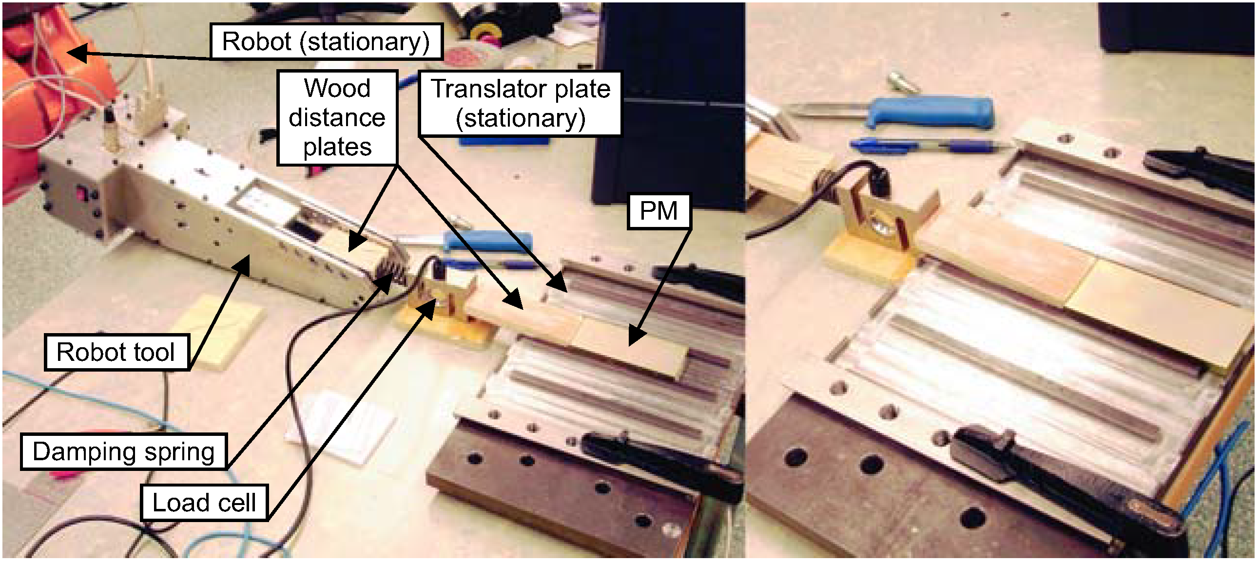
2.1.1. PM Assembly Force Experimental Setup

Before an automation method can be developed, the requirements for the automation must be determined. For the PM surface mounting, it is essential to know the maximum required assembly force. A preliminary approximation of the required force was made by pulling a PM on a steel plate using a dynamometer. Later, the prototype PM mounting robot tool was used in a more controlled assembly force experiment. The robot tool was then held by the IRB4400 robot, while pushing a PM inside a translator plate slot. A load cell, recording the push force, and a damping spring, used to get a softer and more controlled PM movement, were mounted between the tool and the PM. The experimental setup is shown in Figure 2.
Figure 2. The PM assembly force experimental setup. (Left) The PM is being pushed forward; (Right) the PM has reached is final position.
Machines 02 00219 g002

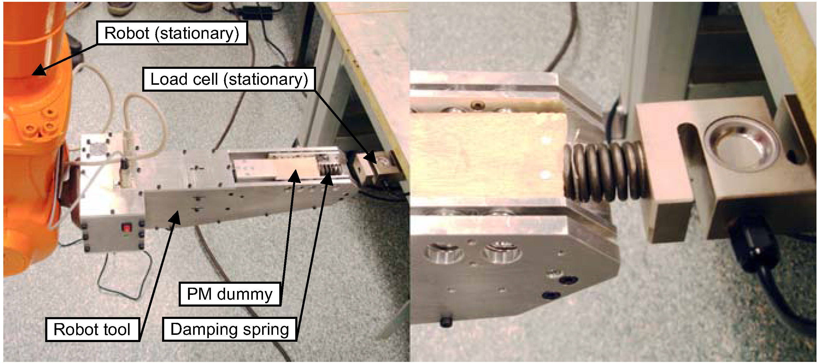
2.1.2. Robot Tool Assembly Force Experimental Setup

The available assembly force, provided by the PM mounting robot tool independently from the robot, was determined for the final tool prototype using the experimental setup shown in Figure 3. In this setup, the robot tool was positioned by the IRB4400 robot to push a PM dummy, made from plastic and wood, against a fixed load cell. A damping spring was mounted between the dummy and the load cell. In the experiment, the spring was compressed until the maximum available feeding force, recorded by the load cell, was reached.
Figure 3. The robot tool assembly force experimental setup. (Left) The slide is in its home position; (Right) it has been fed forward pushing against the load cell.
Machines 02 00219 g003

2.1.3. Economic Calculations

In the economic comparison between the presented automation method and manual assembly, the net present value (NPV) and the payback period were calculated. With manual assembly as a base scenario, the NPV was used to predict the economic value of changing to automated assembly, and the payback time was used to predict when the investment started to be profitable. The NPV is given through:
Machines 02 00219 i001
Where n is the economic lifetime of the investment, Ct is the net cash flow at time t and I is the discount rate. Solving the equation:
Machines 02 00219 i002
gives the payback period, T.

2.2. Requirements on the Automation

Below follows a summary of the most important requirements for automated PM surface mounting on the UU WEC translator. The requirements were defined through manual assembly experience, and the required assembly force was preliminary approximated, as presented in Section 2.1.1.
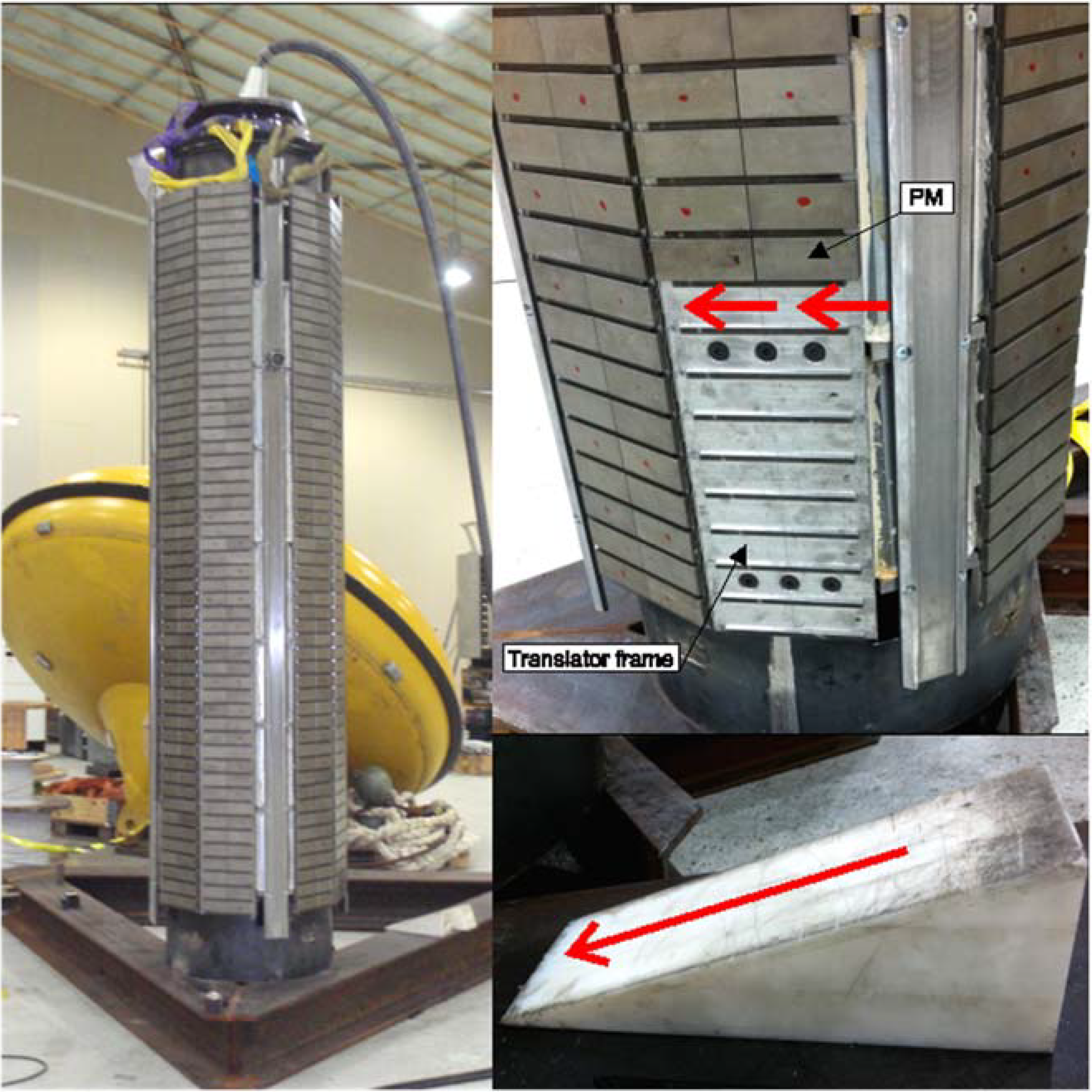
  • In total, 848 PMs should be mounted on the eight sides of the translator, with a shifted PM polarization direction for every PM row.
  • The required force for sliding one PM into the translator frame was determined to be about 100 N.
  • Mechanical collateral fixation of the PMs on the translator sides is required.
  • Damaging the PMs during the assembly must be avoided.
  • Strong magnetic forces between the PMs, between the PMs and the translator and between the PMs and other equipment must be handled.
  • Separation of individual PMs from delivered stacks, with PMs separated by wood plates, is required.
  • Simple, robust and not unnecessarily expensive equipment is desired.
  • A flexible automation method that can be adapted for other rotor designs is desired.

2.3. Robot Cell and Equipment Design

This section presents the final versions of the developed robot cell and the constructed prototype equipment.

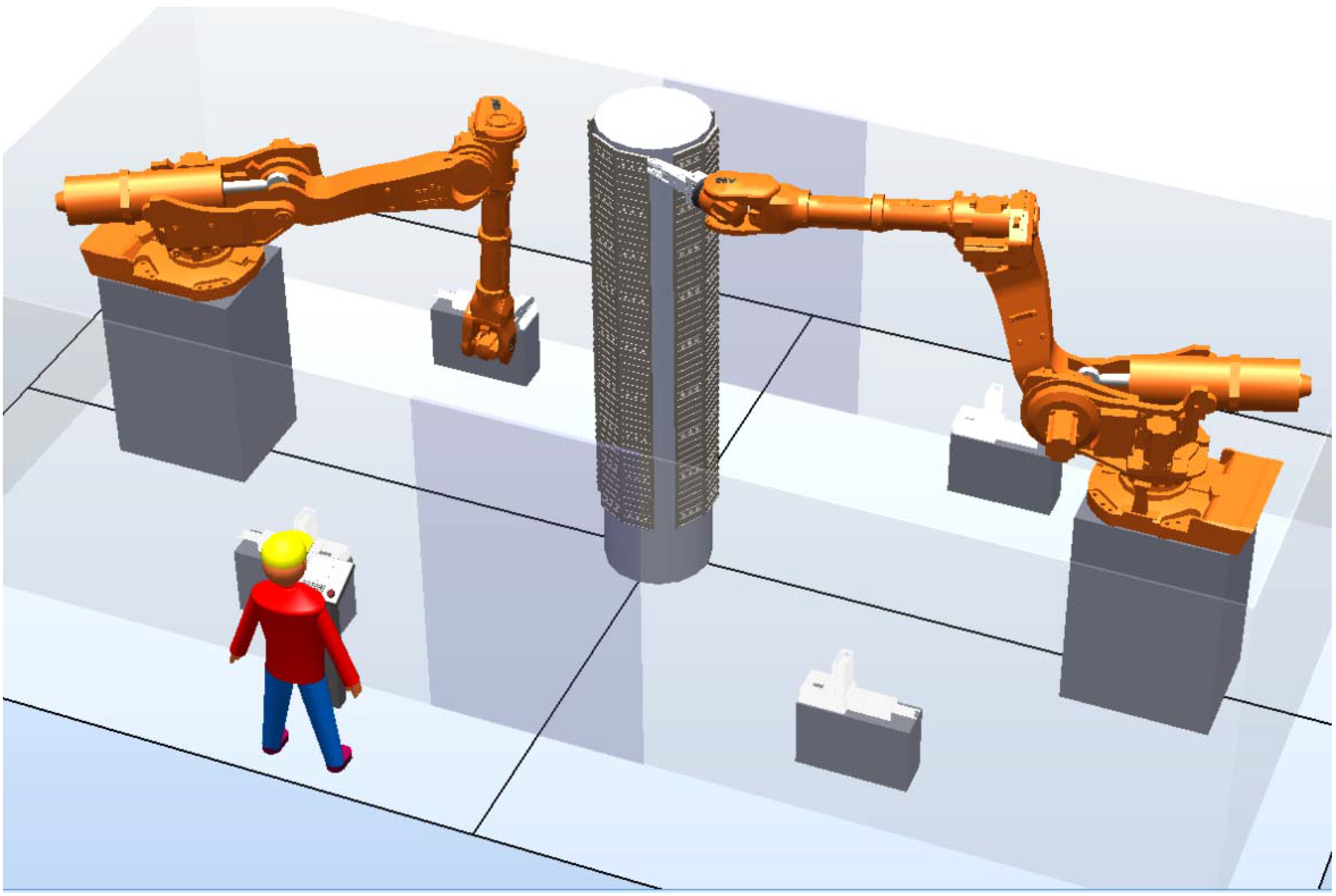
2.3.1. Robot Cell Layout

From the requirements presented in Section 2.2, a robot cell layout for automated PM surface mounting on the UU WEC translator is suggested. Figure 4 shows a RobotStudio model of the cell, including all equipment and programming. In this cell, two ABB IRB6650S-125 kg/3.5 m IRC5 M2004 robots are mounting PMs on two sides of the translator simultaneously. The robots are equipped with PM mounting tools, while the PMs are separated and delivered in four PM delivery stations. Two delivery stations are assigned each to one robot, while the two stations each carry one direction of polarization. The robots are placed on 1.5 m-high pedestals, so each has a full reach over one half of the translator.
Figure 4. A RobotStudio model of the developed robot cell.
Machines 02 00219 g004
The assembly process starts with an empty translator being transported into the cell, e.g., using a gantry, and being placed with high positional accuracy between the robots while the PM delivery stations are being loaded manually. The PM assembly process consists of the robots picking up one PM each from the delivery stations and mounting it on the translator frame. This process is then repeated until all translator sides are completely covered with PMs. Finally, the translator is transported out of the cell. All programmed robot targets were related to different work object coordinate systems, defined and adjusted for the translator and PM delivery stations in the robot programming. Hence, new robot targets could automatically be created when needed, using offset values to the defined equipment dimensions.

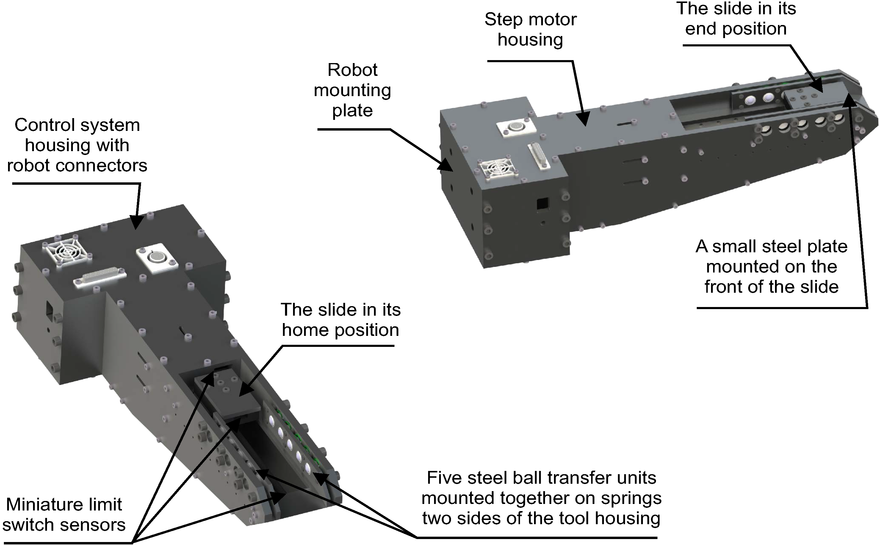
2.3.2. PM Mounting Robot Tool Design

The PM mounting robot tool design, explained in Figure 5, is the heart of the suggested robot cell. Standard mechanical components are used in the design, and the tool housing is made mainly from flat parts in high-strength aluminum, which are screwed together. Hence, a low-density and, to large extent, non-ferromagnetic tool is achieved, and the total component cost for one tool prototype is limited to about 5000 EUR.
Figure 5. The developed PM mounting robot tool design and its main components.
Machines 02 00219 g005
Picking up a PM with high accuracy is achieved using a passive method with steel ball transfer units mounted on the tool. To pick up a PM from the delivery station, the robot turns its tool upside down and then lowers it down over the PM from above. As the tool approaches the PM, the attraction force between the steel balls and the PM rises, until it is larger than the gravity force acting on the PM, and the PM jumps into the tool. The ball transfer units are mounted on the tool housing with springs. As a result, a high accuracy PM position inside the tool is achieved, and full contact between the steel balls and the PM is assured. A small steel plate is mounted on the front of the tool slide, attracting the PM being picked up and thereby pulling it against the slide. A miniature limit switch sensor mounted on the front of the slide detects when a PM is in position.
The PM is pushed onto the translator by moving the slide, which is mounted on two miniature linear guiding systems, with a stepper motor-driven ball screw. Two miniature limit switch sensors detect when the slide has reached the end positions in the tool.

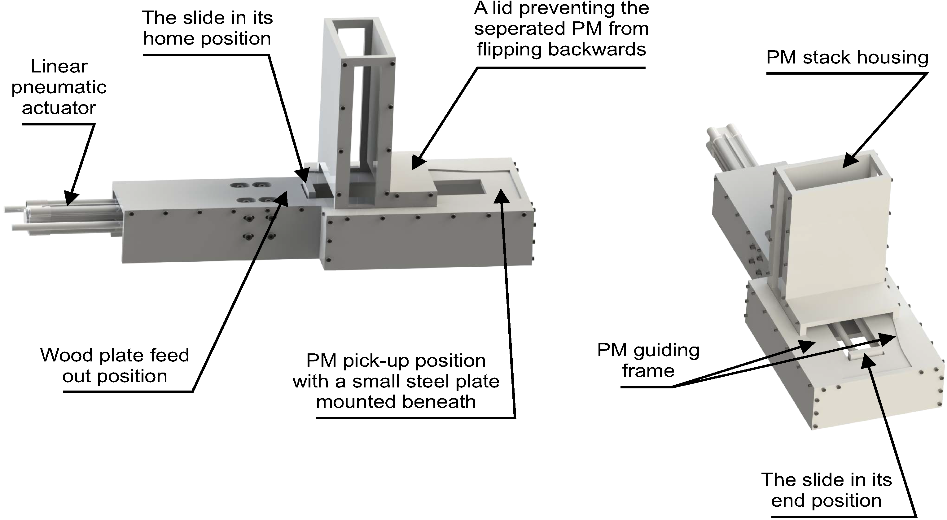
2.3.3. PM Delivery Station Design

The PM delivery station design is presented in Figure 6. Standard mechanical components are used in the design, and the housing is made mainly from flat parts in plastic, which are screwed together. This limits the total component cost for one delivery station prototype to about 2500 EUR.
Separating an individual PM from the PM stack, holding up to 10 PMs, is achieved using a linear pneumatic actuator. As the slide is pushed forward, the bottom PM is separated from the stack and directed by the guiding frame to the pick-up position. The stack then moves downwards due to its weight force, and the bottom wooden plate is pushed away in the opposite direction as the slide returns. The process is monitored in the robot programming. A small steel plate is mounted under the PM pick-up position, holding down the PM when the robot tool approaches from above and, thereby, reducing the mechanical pulse while the PM is jumping into the tool.
Figure 6. The developed PM delivery station design and its main components.
Machines 02 00219 g006

2.3.4. PM Mounting Frame Design

To simplify the assembly, a redesigned slot pattern on the translator is introduced, making it possible to eliminate the support bars used to fix the PMs onto the translator. The new pattern provides full collateral PM support, while still being adapted for machining, i.e., without sharp corners. The PM mounting frame prototype can hold up to 10 PMs.

3. Results and Discussion

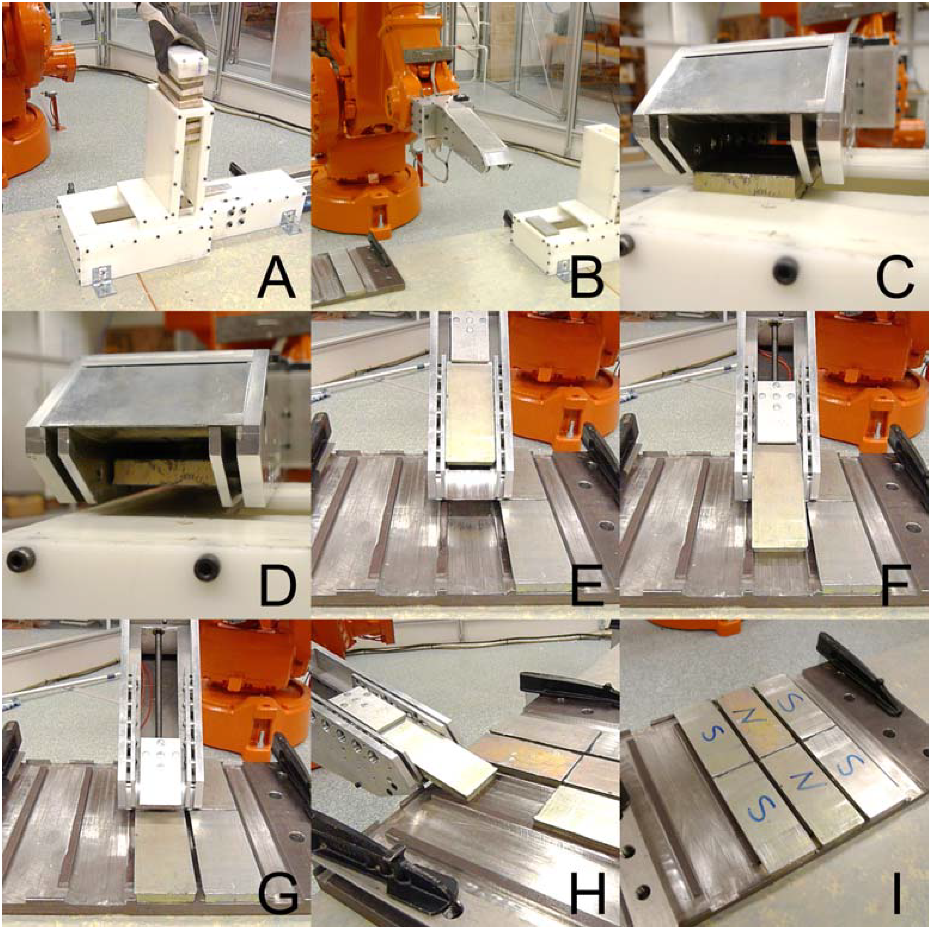
3.1. Experimental Results

The function of the constructed equipment prototypes and the suggested PM assembly procedure were validated through robotized PM surface mounting experiments. Photos of the full assembly procedure are shown in Figure 7. Online teach pendant programming was used to visually adjust the robot targets to the mounting frame geometry. The assembly process was deemed to be robust, but high positioning accuracy was necessary to avoid errors. There was no indication of the PMs being damaged during the assembly. The required force for sliding one PM into the translator frame was determined to be about 300 N by using the experimental setup presented in Section Section 2.1.1. The available assembly force in the robot tool was determined to be about 700 N, using the experimental setup presented in Section 2.1.2. Simulations in RobotStudio validated that the chosen placement and model of the robots provided sufficient robot reach around the full translator frame to complete the full assembly.
Assembling six PMs on the PM mounting frame prototype was completed in 78 s, excluding the time for the manual loading of PMs in the delivery station. Sliding off one PM from the tool onto the mounting frame and pulling back the slide in the tool took slightly less than 9 s, picking up a PM from the delivery station took slightly less than 2 s, and the remaining time was used for moving the tool from the delivery station and positioning against the mounting frame. Combining the experimental cycle time results with the RobotStudio simulation gives a total PM mounting cycle time estimation of about 110 min per translator or about 15 s per PM. Including time estimations for the manual transporting of the translator into and out of the cell and the manual loading of the PM delivery stations, the total PM assembly cycle time for one UU WEC translator in the suggested robot cell is estimated to be about 160 min. It is then assumed that the PM delivery stations are redesigned to hold stacks with at least 212 PMs each, so that reloading during the assembly can be avoided. This cycle time gives a production pace of six translator PM assemblies per day with double-shift work and full utilization of the capacity. From earlier assembly experience, the cycle time for manual PM assembly of one UU WEC translator is estimated to be about 20 h with four workers. Hence, in terms of capacity, the suggested robot cell is equal to 7.5 manual assembly stations.
Figure 7. The full assembly process performed with the prototype robot cell: the PM delivery station is manually loaded (A); the PM mounting robot tool is turned upside down (B); a PM is picked up into the tool (C,D); and six PMs are mounted on the PM mounting frame (EI).
Machines 02 00219 g007

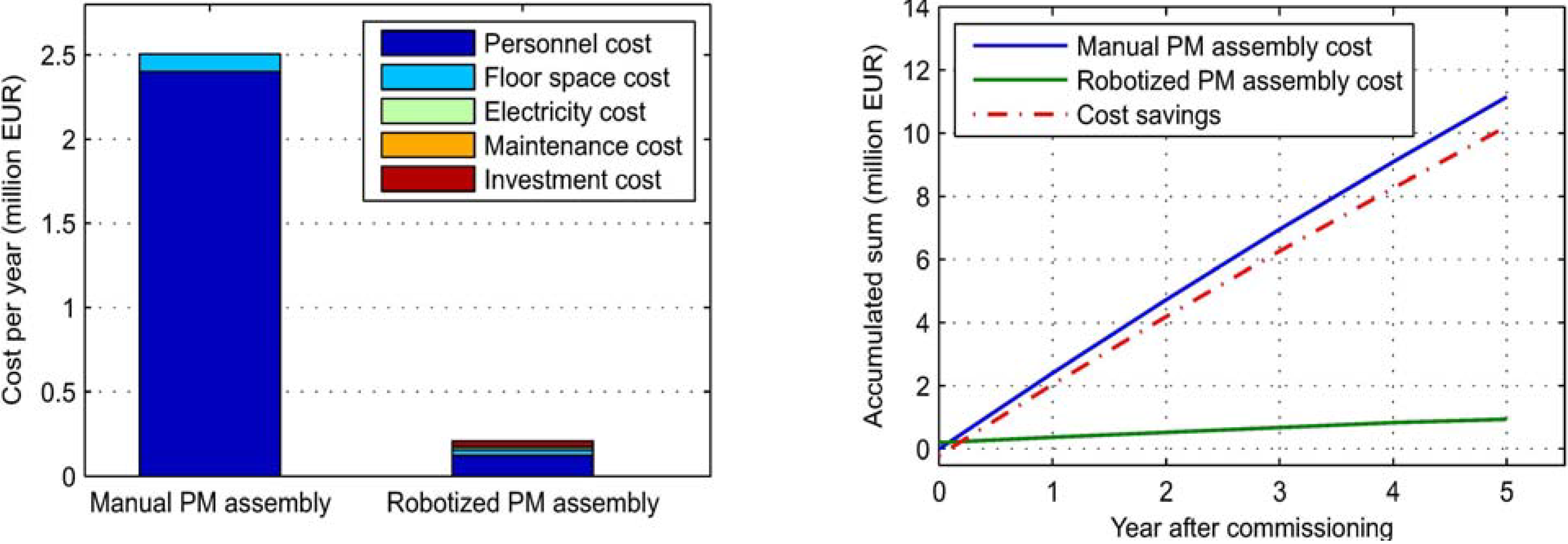
3.2. Economic Analysis

From the estimated investment costs presented in Table 1, including an increased PM delivery station cost, due to the necessary redesigning of the station, the total robot cell cost is estimated to be 200,000 EUR. Comparing one robot cell to 7.5 manual stations, using Equations (1) and (2) with the running cost parameters presented in Table 1 and assuming full capacity utilization gives an NPV of about 10,000,000 EUR and a payback period of about one month for the suggested PM assembly method. The PM assembly cost per translator can easily be calculated to be about 140 EUR with automated assembly and 1670 EUR with manual assembly, indicating a cost saving of over 90%. Figure 8a presents the total cost per year for manual and automated PM assembly, divided into major cost units, while Figure 8b presents the accumulated costs during the economic lifetime of the investment.
Table 1. Investment costs and running costs for robotized and manual PM assembly.
ParameterValue
Robotized assembly investment cost units per cell
Industrial robots including pedestals150,000 EUR
PM mounting robot tools20,000 EUR
PM delivery stations20,000 EUR
Cell enclosure, safety, control and installation10,000 EUR
Robotized assembly running cost parameters per cell
Number of personnel1
Personnel cost30 EUR/h
Factory floor space required36 m2
Power consumption20 kW
Yearly maintenance10,000 EUR
Investment economical lifetime5 years
Investment discount rate4%
Investment rest value40,000 EUR
Manual assembly running cost parameters per station
Number of personnel4
Personnel cost20 EUR/h
Factory floor space required16 m2
Shared running cost parameters
Factory floor space cost0.1 EUR/m2/h
Electricity cost0.1 EUR/kWh
Yearly production time4000 h
Figure 8. (a) Yearly costs divided into major cost units. (b) Accumulated costs and cost saving.
Machines 02 00219 g008

3.3. Discussion

The layout and prototype equipment used in the experimental setup presented in Section 3.1 differ somewhat from the suggested robot cell layout presented in Section 2.3.1. The most important differences are that another industrial robot model is used, only one robot and one PM delivery station are used, the robot pedestal is missing and the PM mounting frame prototype is placed on a table instead of a translator standing on the floor. Nevertheless, the presented experimental and simulation results are still argued to validate the complete suggested robot cell. It could be pointed out that PM mounting on a standing translator frame has not been demonstrated in the experiments. However, the only difference between these assemblies is the direction of the gravity force relative to the assembly, which only has a marginal effect on the PM compared to the actual assembly force. It is therefore assumed that the placement of the PM mounting frame prototype does not influence the PM mounting.
The preliminary approximation of the required assembly force was about one third of the experimentally-decided maximum required assembly force. The main reasons for this difference are probably that, in the first experiment, a plane steel plate without slots was used with older PMs, perhaps being somewhat demagnetized due to wear. Therefore, the second experimental assembly force result is assumed to be a better approximation. The experimentally-determined available assembly force in the PM mounting robot tool prototype was more than twice the required assembly force. This margin provides some robustness to the robot cell. The presented economic comparison is very sketchy; it is not aiming to include all of the details, but rather to provide rough estimations. Still, the presented results strongly indicate that the presented robot cell automation would bring substantial cost savings compared to manual assembly. Apart from the economic analysis, another benefit with robotized PM assembly is that very repetitive, heavy and possibly hazardous manual tasks are eliminated. It can be argued that by implementing the presented automation, manual labor opportunities are lost. On the other hand, for the UU WEC concept to be commercialized at all, assembly automation is likely necessary, especially if the production is to be placed in high salary countries. Moreover, new jobs related to the robot cell are created.
Using industrial robots brings high flexibility to the robot cell compared to using some of the existing stiffer equipment for PM surface mounting [6]. Different robot models, more robots or, e.g., a rotational table can be used to achieve sufficient reach for other translator geometries. The process can thus easily be adjusted to such changes by adjusting some parameters of the programming. Changing the number of robots also affects the investment cost, running costs, cycle time and floor space footprint. The suggested robot tool and PM delivery station designs are scalable and can consequently be adjusted for reasonable changes to the PM size. However, for other PM shapes, considerable equipment redesigning might be necessary. A possibly limiting parameter is that it must be possible to slide the PMs onto the rotor. If additional PM fixation is required, such as gluing or clamping, the presented method must be adapted for the integration of this extra assembly step [13,14]. Mounting the PMs from above onto the rotor, i.e., without sliding, could facilitate gluing fixation [5]. This would result, though, in a much higher assembly force, bringing with it the need for more robust and, thereby, more expensive equipment and increasing the risk of damaging the PMs. In some applications, e.g., for PMs buried in the rotor body, mounting from above is not possible.
Before the suggested robot cell can be integrated in a production line, a solution making it possible for the robots to know the exact position of different translators placed in the cell must be integrated. The translator body itself comes with high geometrical accuracy, but is likely to be difficult to position with sufficient accuracy. An accurate positional calibration for the translator, where the work object coordinate system assigned to the translator in the robot programming is automatically adjusted to the actual translator position, must therefore be performed. Two alternative positional calibration methods that are likely to be suitable are to use a proximity sensor mounted on the robot tool [15] or to use a machine vision system [16].
From the robot cell experiment experience, some suggestions for further improvements to the robot cell are obtained. To begin with, the robot tool could be improved in several ways. The most obvious improvement would be to speed up feeding a PM off the tool by changing to a motor delivering sufficient torque at higher rotational velocities. Two other possibilities are to integrate the PM delivery station into the robot tool or to redesign the tool to achieve the mounting of several PMs at the same time. The latter change might, however, reduce the flexibility of the automation. As suggested in Section Section 3.1, a simple, but important improvement to the PM delivery station would be to increase its capacity. Introducing chamfers to the PM mounting frame design, guiding the PMs into the slots, could improve the robustness of the PM mounting operation and lower the demands on the positional accuracy of the robot tool vis-à-vis the translator. Replacing the small steel plate mounted under the pick-up position on the PM delivery station with an electromagnet (holding down the PMs more effectively) could result in further controlled picking up of the PM. Adding extended sensor supervision to the robot cell, e.g., to confirm that the PM polarization direction is correct, to check the PMs for defects before being mounted and to use a machine vision system to prevent assembly errors during the PM mounting onto the translator could also improve its robustness [17].
The investigated UU WEC translator design includes a very large number of Nd-Fe-B PMs. With a growing demand and limited resources for these PMs, the price has risen lately and is likely to continue to rise. Hence, for the UU WEC concept, it might be necessary to change to, e.g., a completely redesigned ferrite magnet translator. This would also require a new assembly method. It is likely that some of the presented findings can be used in such future work. Furthermore, it is also likely that electric machines using Nd-Fe-B PMs will continue to be used, at least in other applications.

4. Conclusions

A robotized PM surface mounting assembly method for electric machine rotors has been presented and validated through experiments in an experimental robot cell setup using equipment prototypes and through offline robot simulations. The translator of the UU WEC generator has been used as an example of a rotor with surface-mounted PMs. Compared to manual assembly, it is indicated that the presented automation method could bring substantial cost savings, while eliminating repetitive, heavy and possibly hazardous manual tasks. The presented robot cell can be adjusted for different machine geometries and sizes, including rotating machines. Suggestions for further work for successfully taking the robot cell into service have been discussed, including the integration of a positional calibration system.

Acknowledgments

The authors are grateful to David Gombrii, Gerda Sidwall Thygesen, Marcus Linder and Senad Apelfröjd for contributing to this work. This work was supported by the Swedish Research Council under Grant Number 621-2009-3417.

Author Contributions

E.H. contributed to the design and validation of the developed equipment and process and was responsible for the analysis of the experimental results and for writing the article. D.S. is the main person responsible for the design and validation of the developed equipment and process and has been responsible for constructing the prototype equipment. E.H. and D.S. contributed equally to the assembly force experiments. M.L. was responsible for defining the project and supervised and gave input.

Conflicts of Interest

The authors declare no conflict of interest.

References

  1. Haring, T.; Forsman, K.; Huhtanen, T.; Zawadzki, M. Direct drive – opening a new era in many applications. In Conference Record of the 2003 Annual Pulp and Paper Industry Technical Conference, Charleston, USA, 16–20 June 2003; pp. 171–179.
  2. Hsieh, M.F.; Hsu, Y.C.; Dorrell, D.G. Design of large-power surface-mounted permanent-magnet motors using postassembly magnetization. IEEE Trans. Ind. Electron. 2010, 57, 3376–3384. [Google Scholar]
  3. Itagaki, T.; Hiwasa, H.; Haga, K. Design and manufacturing technology of Fuji Electric’s large-capacity, air-cooled turbine generator. Chall. Power Eng. Environ. 2007, 1–2, 395–399. [Google Scholar]
  4. Uchida, H.; Amemiya, Y. FANUC—The planning and development of a highly advanced robotized production system for servo motors. Assem. Autom. 1998, 18, 270–274. [Google Scholar]
  5. Franke, J.; Tremel, J.; Kühl, A. Innovative developments for automated magnet handling and bonding of rare earth magnets. In Proceedings of the 2011 IEEE International Symposium on Assembly and Manufacturing ISAM, Tampere, Finland, 25–27 May 2011; pp. 1–5.
  6. Joseph, E.; Tremel, J.; Hofmann, B.; Meyer, A.; Franke, J.; Eschrich, S. Automated magnet assembly for large PM synchronous machines with integrated permanent magnets. In Proceedings of the 3rd International Electric Drives Production Conference, Nuremberg, German, 29–30 October 2013; pp. 1–6.
  7. Tremel, J.; Hofmann, B.; Risch, F. Handling and fixation of permanent magnets. Adv. Mater. Res. 2013, 769, 3–10. [Google Scholar]
  8. Sugimori, Y.; Kusunoki, K.; Cho, F.; Uchikawa, S. Toyota production system and Kanban system materialization of just-in-time and respect-for-human system. Int. J. Prod. Res. 1977, 15, 553–564. [Google Scholar]
  9. Hong, Y.; Hultman, E.; Castellucci, V.; Ekergård, B.; Sjökvist, L.; Soman, D.E.; Krishna, R.; Haikonen, K.; Baudoin, A.; Lindblad, L.; et al. Status update of the wave energy research at Uppsala University. In Presented at the 10th European Wave and Tidal Energy Conference (EWTEC), Aalborg, Denmark, 2–5 September 2013.
  10. Egaña, I.; Elosegui, I.; Rico, A.G.; Echeverrfa, J.M.; Martinez-Iturralde, M. Flat magnets in surface-mounted permanent magnet machines: Influence and design. In Proceedings of the International Symposium on Power Electronics, Electrical Drives, Automation and Motion (SPEEDAM), Ischia, Italy, 11–13 June 2008; pp. 697–701.
  11. Hultman, E.; Leijon, M. Utilizing cable winding and industrial robots to facilitate the manufacturing of electric machines. Robot. Comput. Integr. Manuf. 2013, 29, 246–256. [Google Scholar]
  12. Hultman, E.; Ekergård, B.; Leijon, M. Electromagnetic, mechanical and manufacturing properties for cable wound direct-drive PM linear generators for offshore environments. In Presented at the 31st International Conference on Ocean, Offshore and Arctic Engineering, Rio de Janeiro, Brazil, 1–6 July 2012.
  13. Aleksashkin, A.; Mikkola, A. Literature Review on Permanent Magnet Generators Design and Dynamic Behaviour; Research Report 77; Lappeenranta University of Technology: Lappeenranta, Finland, 2008. [Google Scholar]
  14. Binder, A.; Schneider, T.; Klohr, M. Fixation of buried and surface-mounted magnets in high-speed permanent-magnet synchronous machines. IEEE Trans. Ind. Appl. 2006, 42, 1031–1037. [Google Scholar]
  15. Hultman, E.; Leijon, M. Six-degrees-of-freedom (6-DOF) work object positional calibration using a robot-held proximity sensor. Machines 2013, 1, 63–80. [Google Scholar]
  16. Chen, S.; Li, Y.; Ming Kwok, N. Active vision in robotic systems: A survey of recent developments. Int. J. Robot. Res. 2012, 30, 1343–1377. [Google Scholar]
  17. Okumura, S.; Take, N.; Okino, N. Error prevention in robotic assembly tasks by a machine vision and statistical pattern recognition method. Int. J. Prod. Res. 2005, 43, 1397–1410. [Google Scholar]

