3.2. Mechanical Design and Feasibility of Construction
Once the basic topology of the rotor part of the magnetic circuit had been chosen, consideration was given to how it should be implemented. The rotor topology chosen was a spoke design with tangentially magnetized PMs placed between pole shoes. It was decided that the pole shoes should be fastened with bolts on their inner side. Rough calculations of the forces expected to act upon the pole shoes gave the minimum bolt diameter required, limiting the minimum width of the inward side of the pole. This constraint was then used in the electromagnetic design.
A technical perspective drawing of the rotor design can be seen in
Figure 1.
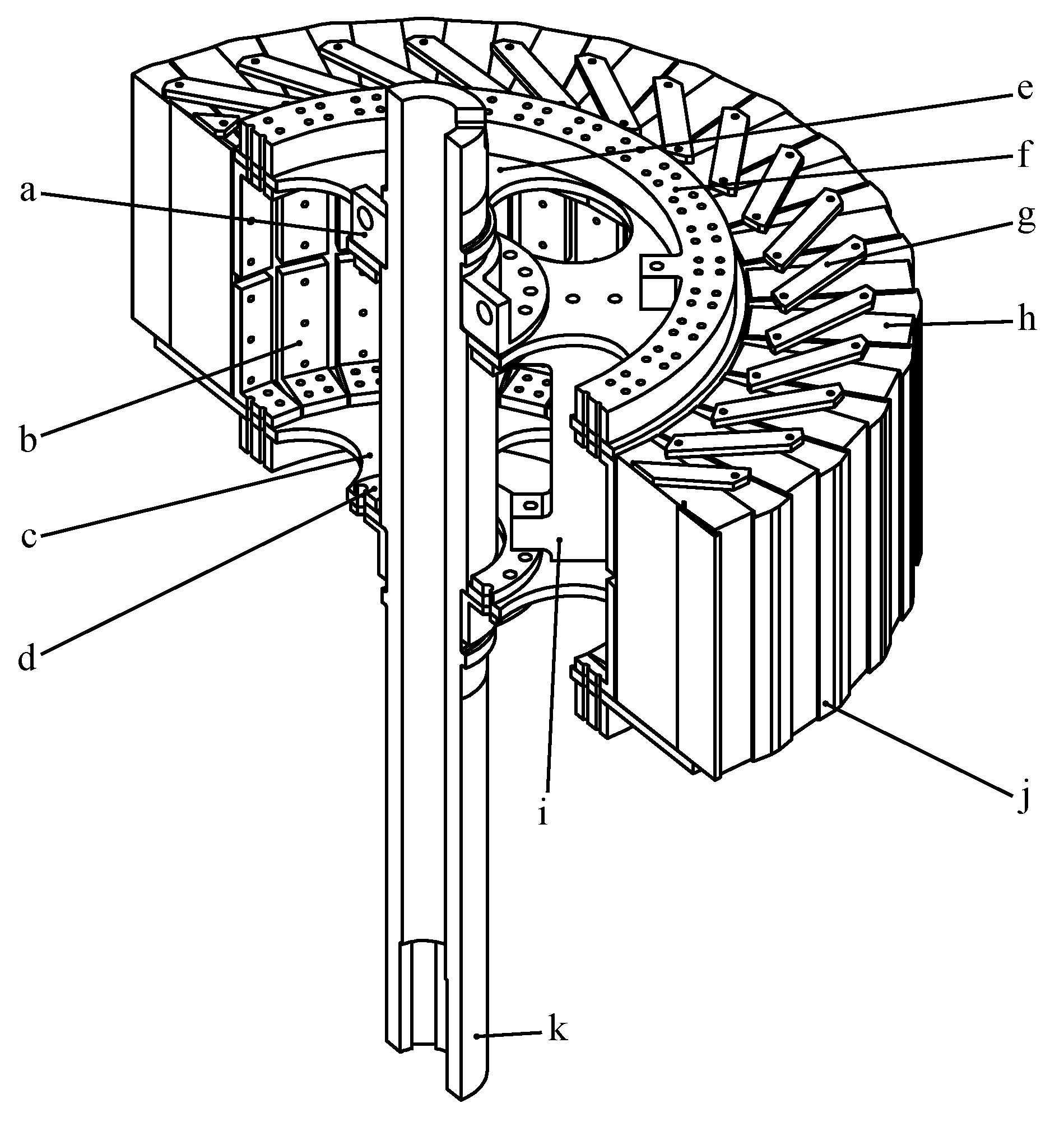
Figure 1.
Isometric cut-away view of the ferrite rotor design. Half of the rotor has been removed to make the internal structure more visible. Parts indicated are: (a) fastening flange; (b) L-shaped pole shoe holder; (c) rotor bottom plate; (d) small stiffening ring; (e) top rotor end plate; (f) large stiffening ring; (g) bar for holding the magnet in place; (h) permanent magnet; (i) inner supports; (j) pole shoe; and (k) shaft.
For ease of assembly and structural reasons, laminated poles were opted against, in favor of solid poles. Eddy currents in the solid poles is not expected to pose a problem, since the magnetic flux does not vary significantly in the rotor poles. The pole shoes were mounted on a support structure, consisting of two rotor end plates with plate struts in-between, using a pair of L-shaped holders per pole (in
Figure 1c,e,i,b, respectively). The rotor support structure is then fastened to the generator shaft using two flanges (a in
Figure 1) that are bolted together. Aluminum was used for most of the support structure, due to lower weight and ease of manufacture, as aluminum is considered to be easier than nonmagnetic steel to machine into required shapes. The lower fatigue resistance of aluminum is not a problem, since long time operation of the research prototype is not expected.
The bolted joints were calculated in a simplified manner with factors of safety in the range of 3 to 7. The friction between the clamped parts should be sufficient to transfer the shearing forces to avoid shearing the bolt. To ensure this the shearing force times a friction coefficient was added to the tension force to get the required minimum clamping force.
In the final stages of the mechanical design the design was reviewed and plans for how it should be assembled was made, to ensure that all parts could be mounted.
The forces and torques on the pole shoes and rotor as a whole were obtained from the electromagnetic simulations for the three cases: Normal operation, three phase short circuit to ground and two-phase phase-to-phase short circuit. The case with the largest force was then used when computing the stresses. The force imbalance resulting from an off-center rotor was also calculated.
The force on a single pole shoe during normal operation varies between 1400 N and 1500 N for the radial component and around 65 N for the tangential component. Worst case loading, the two phase short circuit, gives the radial component at about 2000 N. Torque on the rotor during normal operation is 930 Nm with a ripple at six times the electrical frequency. During a two-phase short circuit the torque can rise to as much as 8300 Nm. A 3 mm displacement of the rotor from being concentric with the stator creates a force unbalance of 10 kN.
The rotor end plates have holes to allow access to the interior of the rotor, which is needed both for assembly and for later experiments with the generator. Slotted spring pins are used to position the pole shoes relative to the bottom rotor end plate. Radial positioning of the bottom rotor end plate relative to the shaft is done with a tight clearance fit. All joints in the design are held together by bolts.
To hold the rotor relative to the stator two composite boards and eight steel bars (not shown in
Figure 1) are used. The steel bars are fastened to the stator using dove tail keys. The composite boards are fastened to the bars using bolts and positioned using ledges on the end of the bars. The bearing housings are positioned by a narrow clearance fit with the composite boards and held in place with bolts.
The height of the pole shoes is the same as the height of the stator, 224 mm. The average PM will be slightly higher since a slightly too high magnet had to be chosen to ensure the PM always is the full height of the pole shoe because of tolerances. The size of the magnets in the plane of rotation is 38 mm by 122.5 mm with magnetization parallel with the shorter side.
The initial material thickness of the L-shaped holders, b in
Figure 1, was chosen as 10 mm because of available standard extruded aluminum profiles. The thickness of the rotor end plates, c and e in
Figure 1, was chosen as 10 mm. The shaft was chosen to have the same outer diameter 95 mm outer diameter as the old design. These material thicknesses gave sufficient strength to withstand the expected magnetic and inertial loads on the structure during the worst case fault, a two-phase short circuit at rated speed. The strength was also sufficient to keep deformations under acceptable values.
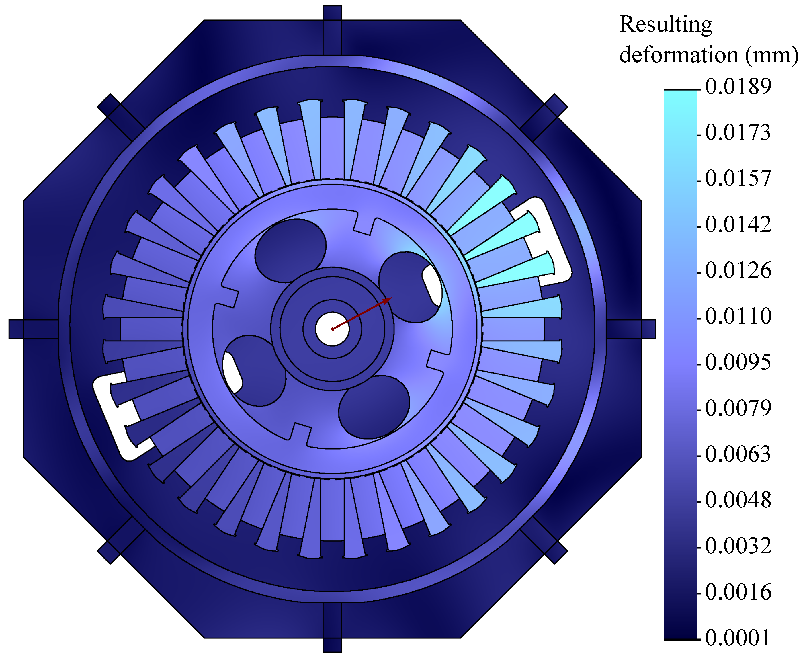
The stiffness against an unbalanced magnetic pull was also investigated. Simulations were made with the force imbalance of 10 kN, calculated for a 3 mm off-center displacement of the rotor, applied to the undeformed generator. To realistically distribute the force on the poles, the unbalanced magnetic pull was superimposed to the attractive force between rotor and stator at nominal air gap. The change in force on each pole from the force at normal air gap was assumed to be proportional to the change in air gap width when the rotor is displaced and directed in the radial direction. The reaction force on the stator was modeled similarly but with a continuous stress distribution rather than discrete forces acting on segments. The magnetic forces are modeled as acting on the surface of the poles and stator. On the poles the surface stress is constant for each pole and applied normal to the air gap face of the pole. On the stator a continuously varying surface stress distribution is used to apply the magnetic force. The magnetic force on the rotor and stator are matched so that there is no net magnetic force. To simplify simulations the stator teeth were removed from the model since it is mainly the yoke of the stator that holds the stator together. Results of the simulations can be seen in
Figure 2.
Figure 2.
Deformation of the generator under the mechanical loading predicted for a 3 mm off-center rotor applied to the undeformed geometry. The resultant 10 kN force on the rotor is directed along the red arrow. Some parts of the generator geometry have been hidden to make the relevant parts more visible.
The simulation showed that the unbalance in magnetic pull will only cause displacements smaller by more than one order of magnitude than the displacement required to create it, meaning that the structure is sufficiently stiff. If this was not the case, an off-center displacement or rotor eccentricity would give an unbalanced magnetic pull that resulted in a magnetic force that grew faster with deformation than the mechanical force needed to cause the deformation, resulting in the structure collapsing.
Simulations to investigate the natural vibrations of the structure showed modes of vibration at frequencies below the frequency of the torque ripple. The simulations were not expected to give accurate values of the frequencies, due to their simplified nature, but rather to identify modes of vibration that can cause problems. The first mode is shown in
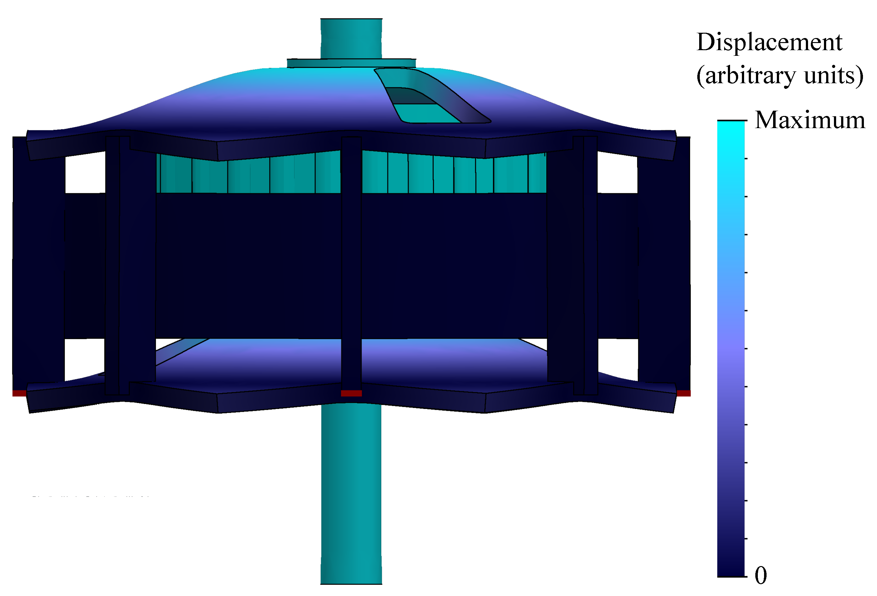
Figure 3 and has a frequency of 53 Hz according to simulations. The structure is held in place by considering four of the lower end of the bars joining the stator and end boards fixed. The stator has been simplified by removing the teeth, the density of the material was then set to keep the mass of the stator constant.
Figure 3.
First natural mode of vibration. Deformations are not to scale and exaggerated to show the shape of the mode. The red boxes indicate where the structure is fixed.
Figure 3.
First natural mode of vibration. Deformations are not to scale and exaggerated to show the shape of the mode. The red boxes indicate where the structure is fixed.
In order to reduce the risk of the discovered modes of vibrations causing problems parts were added to make the structure stiffer. The inner supports, in
Figure 1i, were added to counteract the first mode, where the pole shoes and PMs moves up and down relative to the stator by flexing the rotor end boards, in
Figure 1c,e, and the composite generator end boards, not shown. The thickness of the generator end boards was also increased to 30 mm, from the 20 mm used in the old design. The inner supports also stiffen the structure against modes where the rotor oscillates by tilting relative to the shaft. The large stiffening ring,
Figure 1f, was added to prevent the rim of the rotor from oscillating in a transversal motion but also positively impacts the tilting modes. To counteract a mode where the rotor oscillates in the plane of rotation by bending the shaft the diameter of segment of the shaft inside the rotor was increased to 110 mm. The inner diameter of the shaft was also decreased from 85 mm to 55 mm.
In the final stages of the mechanical design the design was reviewed and plans for how it should be assembled was made, to ensure that all parts could be mounted.
3.3. Electromagnetic Properties
The electromagnetic performance of the new design has been predicted through time stepped FEM simulations. A plot showing the magnetic flux density in the generator at load can be seen in
Figure 4.
Figure 4.
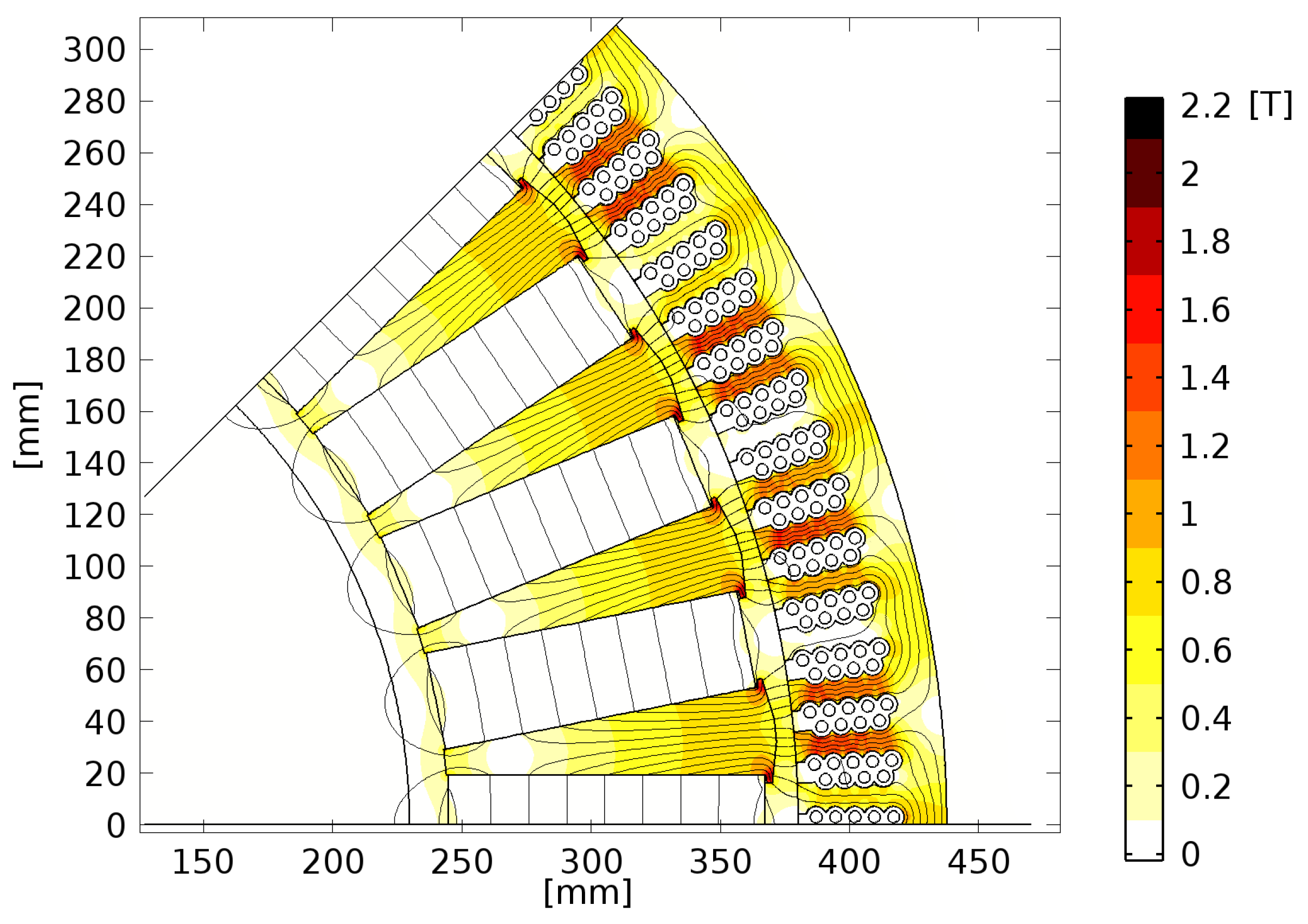
Magnetic flux density and field lines at load, for a 45° sector of the geometry, obtained through Finite Element Method (FEM) simulations. The axis are position relative to the center of rotation and the color scale is magnetic flux density.
Figure 4.
Magnetic flux density and field lines at load, for a 45° sector of the geometry, obtained through Finite Element Method (FEM) simulations. The axis are position relative to the center of rotation and the color scale is magnetic flux density.
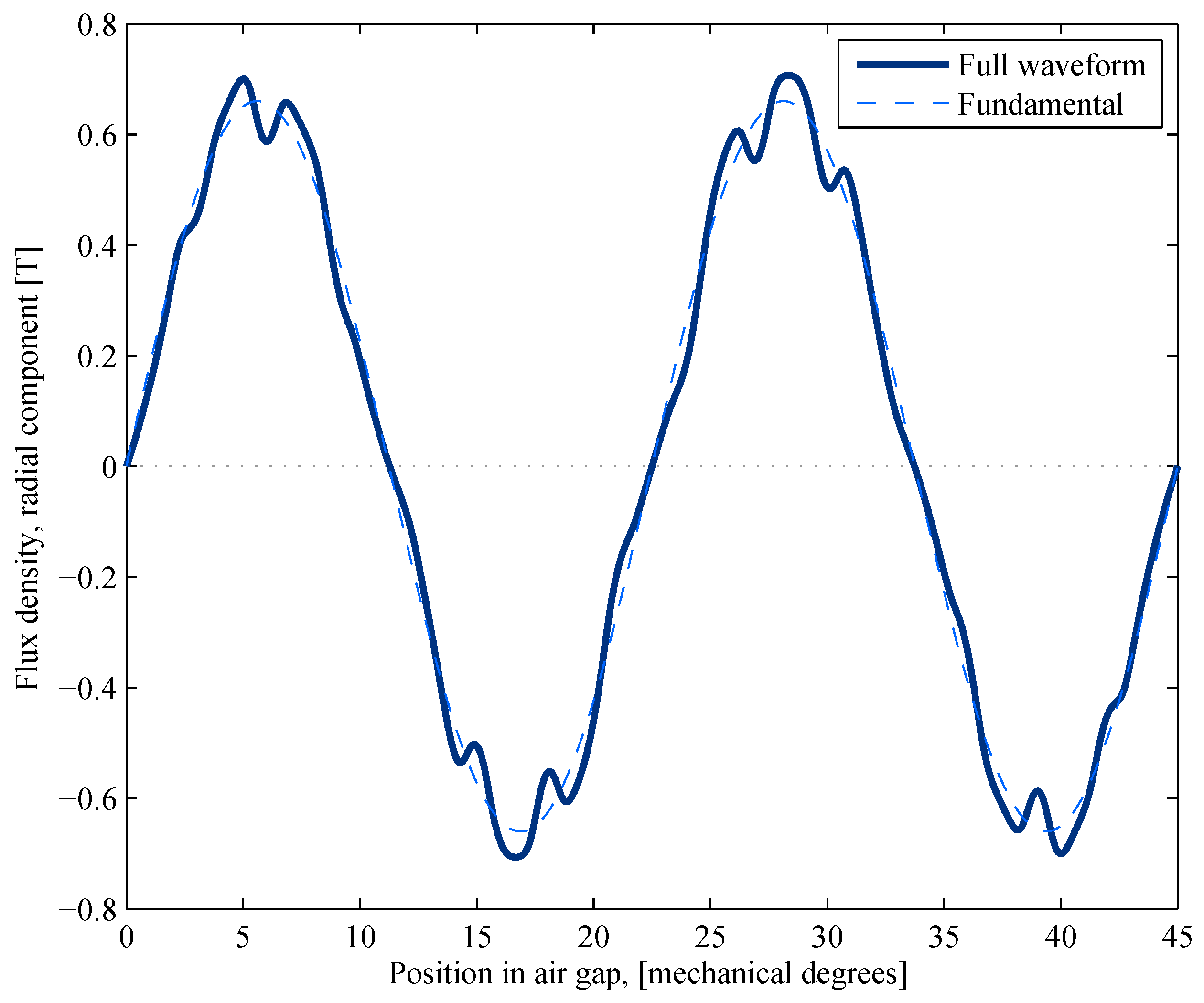
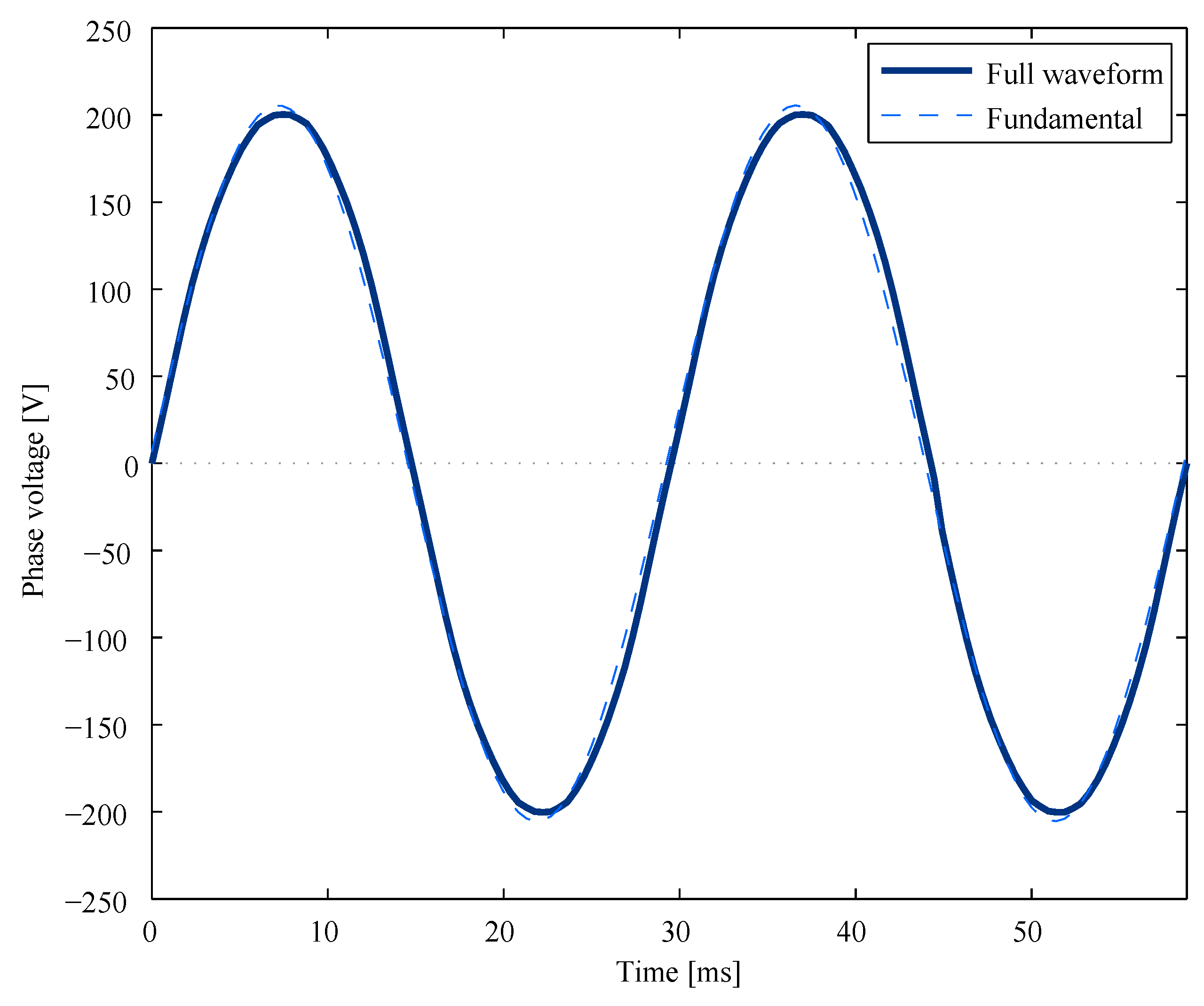
The radial component of the air gap flux density, at no-load, is shown in
Figure 5 and the no-load voltage is shown in
Figure 6.
Figure 5.
The radial component of the air gap flux density waveform and the fundamental of the waveform at no-load, from FEM simulations.
Figure 5.
The radial component of the air gap flux density waveform and the fundamental of the waveform at no-load, from FEM simulations.
Figure 6.
The phase voltage at no-load with the fundamental shown, from FEM simulations.
Figure 6.
The phase voltage at no-load with the fundamental shown, from FEM simulations.
A comparison between the new and original design can be found in
Table 2. All data for the new design are from dynamic simulations with the method described in
section 4, apart from the iron losses which are taken from stationary simulations with the in-house program KALK. The data for the original design are from dynamic simulations with in-house program KALK apart from the iron losses which are taken from stationary simulations.
Table 2.
A comparison of the characteristics of the new design, using ferrite permanent magnets (PMs), and the original design, using neodymium-iron-boron (NdFeB) PMs. Values are at rated load and speed. Data for the new design are from simulations. Data for the original design are from simulations except for weights. Data for the PMs are manufacturers specifications (Sura Magnets AB, (
www.suramagnets.se), for the NdFeB PMs and BJA Magnetics, (
http://www.bjamagnetics.com), for the ferrite PMs).
Table 2.
A comparison of the characteristics of the new design, using ferrite permanent magnets (PMs), and the original design, using neodymium-iron-boron (NdFeB) PMs. Values are at rated load and speed. Data for the new design are from simulations. Data for the original design are from simulations except for weights. Data for the PMs are manufacturers specifications (Sura Magnets AB, (www.suramagnets.se), for the NdFeB PMs and BJA Magnetics, (http://www.bjamagnetics.com), for the ferrite PMs).
| Quantity | NdFeB (Old) Design | Ferrite (New) Design |
|---|
| Rated power [kW] | 12 | 12 |
| Phase voltage, no load (rms) [V] | 172 | 146 |
| Phase voltage (rms) [V] | 167 | 141 |
| Armature current (rms) [A] | 23.9 | 28.5 |
| Armature winding current density (rms) [] | 1.49 | 1.78 |
| Amplitude of air gap flux density fundamental at no load [T] | 0.79 | 0.66 |
| Resistive losses [W] | 275 | 390 |
| Iron losses [W] | 254 | 159 |
| Electromagnetic efficiency [%] | 95.8 | 95.6 |
| Minimum air gap [mm] | 10 | 7 |
| Mass of rotor [kg] | 130 | 407 |
| Mass of PM [kg] | 41 | 158 |
| Moment of inertia [kg/ m] | 16.9 | 34.2 |
| PM material grade | N40 | Y40 |
| Remanence of PM [T] | 1.27 | 0.45 |
| Maximum energy product [kJ/m] | 310 | 47.6 |
The magnetic flux per pole in the 3D simulations was about 10% lower than that of the 2D simulations. There was little variation in flux per pole as the armature current was changed from none to rated load current. The results are in line with prior results obtained [
8].

