Article

Electromagnetic Vibration Analysis and Mitigation of FSCW PM Machines with Auxiliary Teeth

1
School of Mechanical Engineering, Tiangong University, Tianjin 300387, China
2
National and Local Joint Engineering Research Center for Hi-Efficiency and Hi-Performance Electrical Machine System Intelligent Design and Manufacturing, Tianjin 300387, China
*
Author to whom correspondence should be addressed.
Machines 2025, 13(9), 867; https://doi.org/10.3390/machines13090867
Submission received: 5 August 2025 / Revised: 5 September 2025 / Accepted: 12 September 2025 / Published: 18 September 2025
(This article belongs to the Special Issue Advances in Analysis, Control and Design of Permanent Magnet Machines)

Abstract

Auxiliary teeth are usually used in fractional-slot concentrated winding (FSCW) machines for fault tolerance. However, the influence of auxiliary teeth on torque and electromagnetic vibration performance differs with different slot–pole configurations. Thus, this paper investigates electromagnetic vibration and mitigation methods in FSCW permanent magnet (PM) machines with auxiliary teeth. The relationship between yoke forces and tooth parameters of two dual three-phase (DTP) FSCW-PM machines with 12-slot/14-pole configuration and 12-slot/10-pole configuration is studied and compared. Results reveal that (1) the 2p-order airgap electromagnetic force reduces second-order yoke force in the 12-slot/14-pole machine but increases it in the 12-slot/10-pole machine. (2) Through optimized tooth width, slot harmonics can be mitigated, but the fundamental winding magnetic field in the 12-slot/10-pole machine is also weakened, whereas the 12-slot/14-pole machine achieves fundamental field preservation or enhancement. Based on these findings, auxiliary tooth optimization and rotor pole profile shaping are proposed for vibration reduction in 12-slot/14-pole machine. Electromagnetic–mechanical coupled simulations conducted in ANSYS Maxwell/Workbench 2023 demonstrate that the optimized design reduces the cogging torque peak from 11.4 mN·m to 2.9 mN·m (74.6% reduction), suppresses housing surface vibration acceleration by 21%, and maintains the average output torque without reduction.

1. Introduction

With the widespread application of motors in electric vehicles and electric vertical take-off and landing (eVTOL), there has been increasing attention on motors with high power density, high reliability, and low electromagnetic vibration [1,2]. Compared to three-phase integer-slot distributed winding motors, multiphase fractional-slot concentrated winding (FSCW) motors exhibit higher efficiency and reliability due to their shorter end-windings and winding redundancy [3]. However, the FSCW motor inherently contains abundant spatial harmonic components in the magnetic field, leading to significant vibration. Consequently, vibration analysis and optimization for FSCW permanent magnet (PM) motors have become a popular topic of research [4,5,6].
The excitation of low-order electromagnetic vibrations in FSCW-PM motors is mainly generated by the interaction between the fundamental magnetic field and slot harmonics. Therefore, suppressing the slot harmonics can effectively mitigate electromagnetic vibrations [7,8]. In [9], a 20-slot/18-pole V-type interior permanent magnet motor used an eccentric pole design with auxiliary slots on the stator and rotor, suppressing the 11th-order slot harmonic and significantly reducing second-order vibration. In [10], a 12-slot/10-pole (12s10p) single-layer concentrated winding motor suppressed the 7th-order slot harmonic and associated second-order eletromagnetic vibration through unequal tooth-width optimization. However, this method increased cogging torque. In [11], an 18-slot/16-pole double-layer winding motor introduced inter-phase auxiliary teeth, which suppressed 10th-order slot harmonic-induced second-order vibration without sacrificing output torque but doubled torque ripple. Reference [12] proposed intra-slot auxiliary teeth to suppress winding short-circuit fault currents and slot harmonics, but reduced output torque by 33%.
Furthermore, high order airgap electromagnetic forces contribute to low-order vibrations through the tooth modulation effect [13]. Reference [14] compared a 12s10p surface-mounted PM motor with bread-loaf magnets versus conventional magnets. The results indicate that the bread-loaf design produced stronger 2p-order (where p is pole pairs) forces, causing higher second-order vibration. Reference [15] suppressed the 2p-order airgap electromagnetic force by enhancing the 3p, 5p, and 7p harmonics in PM magnetic field, thereby reducing the second-order vibration. The above references show that the 2p-order airgap electromagnetic force enhances the second-order vibration due to the tooth modulation effect. However, high-order airgap forces can also suppress the low-order vibration due to a different tooth modulation effect [16]. Reference [17] reveals that the tooth modulation effect varies with slot opening width, and an analytical model of the tooth modulation effect was proposed in [18] by mapping the tooth-surface radial airgap force to the yoke. However, neglecting the slot-opening force leads to significant errors in tangential force analysis [19].
In summary, the auxiliary teeth (unequal teeth) can reduce slot harmonics and enhance fault tolerance, but they introduce drawbacks such as increased cogging torque [10], higher torque ripple [11], and reduced output torque [12]. Furthermore, existing studies focus on the tooth modulation effect in the equal teeth stator [16,17,18], but analysis with unequal teeth remains scarce.
This paper aims to clarify the impact of auxiliary teeth on electromagnetic vibration in two types of FSCW-PM machines (12s14p and 12s10p) whose slot and pole combinations satisfy 2 p = Q s ± 2 (where Q s denotes the number of slots). The equivalent yoke force model is developed based on the rigid-body theory detailed in Section 2. Then, in Section 3, the impact of auxiliary teeth on winding magnetomotive force (MMF), airgap permeance, and tooth modulation effects is analyzed. Specifically, tooth modulation coefficients incorporating auxiliary teeth are further proposed based on the equivalent yoke force model, which quantifies the transfer mechanism from high-order airgap forces to low-order yoke forces. Based on this analysis, a synergistic approach combining auxiliary tooth-width optimization and rotor shaping is proposed in Section 4 to mitigate electromagnetic vibrations in 2 p = Q s + 2 machines. Finally, in Section 5, Electromagnetic–mechanical coupled simulations conducted in ANSYS Maxwell/Workbench to verify the effectiveness of the optimal design.

2. Equivalent Yoke Force Model

It is well known that electromagnetic forces are mainly acting on the airgap and tooth interface. Forces are transferred by teeth, acting on the yoke, and then cause radial vibration. For convenience of analysis, some simplifications are made as follows [20,21]:
  • The motor’s stator core and housing undergo small elastic deformation;
  • The teeth are considered rigid bodies; under this assumption, forces acting on the teeth are transferred to the interface of teeth and yoke (no deformation-induced force loss);
  • Bending moments can be equivalent to a pair of forces that have the same amplitude, opposite directions, and parallel non-collinear action lines.
According to the assumption 1 to 3, the force equivalence relationships are illustrated in Figure 1. Radial forces are directly mapped to the yoke, while tangential forces are transferred with additional bending moments and then converted into equivalent to radial forces. Since the accuracy of the equivalent forces depends on the stiffness of the teeth and yoke, and the stiffness of the teeth is related to the width, length and elastic modulus, the results of the calculated yoke forces based on the rigid-body assumption may be higher than actual yoke force values under the condition of lower stiffness of the teeth.
The equivalent concentrated forces F r n , F t n and bending moments M n on the tooth shoulders are derived by [16,22]:
F r n = r g θ n Δ θ / 2 θ n + Δ θ / 2 f r cos θ θ n f t sin θ θ n d θ , F t n = r g θ n Δ θ / 2 θ n + Δ θ / 2 f r sin θ θ n + f t cos θ θ n d θ , M n = r g 2 θ n Δ θ / 2 θ n + Δ θ / 2 f t d θ r g F t n .
where f r and f t are the radial and tangential airgap force, respectively, θ n denotes the angular position of the nth tooth, Δ θ denotes the slot pitch of the tooth, r g and r y denote the radii of the airgap and yoke centerline, respectively. Furthermore, based on the rigid-body theory, the concentrated forces and bending moments in (1) are transferred to the yoke centerline, with bending moments expressed as
M y n = M n ( r y r g ) F t n = r g 2 θ n Δ θ / 2 θ n + Δ θ / 2 f t d θ r y F t n .
The bending moment M y n can be equaled to forces F M n , acting on the yoke centerline [21], and the following relationship is established:
M y n = 2 F M n r y sin Δ θ / 2 .
Then, the equivalent radial forces of the bending moment on the yoke can be expressed as
F M r n = F M n + 1 F M n cos Δ θ / 2 = M y n + 1 M y n 2 r y cos ( Δ θ / 2 ) sin ( Δ θ / 2 ) .
Finally, the airgap forces can be equivalently represented as radial force pulse trains with π / Q s spacing acting on the yoke:
f ¯ yr θ , t = n = 0 Q s 1 F r n δ θ 2 n π Q s + n = 0 Q s 1 F M r n δ θ 2 n + 1 π Q s .
Obviously, after the airgap forces are transmitted through the teeth, the distribution and harmonic content of the forces will differ. This phenomenon is called the tooth modulation effect. The harmonic order relationship between airgap forces and yoke forces is detailed in the following sections.

3. Electromagnetic Force Harmonics Analysis

3.1. Airgap Forces and Their Harmonics

The magnetomotive force (MMF) generated by PM and the fundamental component of the winding current across the slotless airgap can be expressed as
F pm θ , t = μ = 2 k + 1 F μ cos μ p θ μ ω e t , k . F wd θ , t = v F v cos v θ ω e t φ 0 .
where μ p and v denote the space orders, p is the pole pairs of the machine, and μ is the odd integer owing to the symmetry in the PM MMF distribution. The electrical angular velocity of the rotor satisfies ω e = 2 π f e , where f e represents the electrical frequency. φ 0 is the initial phase and φ 0 = π / 2 with the control strategy that i d = 0 . The winding MMF spatial orders v are determined by
v = 2 m p d k + p , k . q = Q s 2 m p = N d .
where m denotes the number of winding phases. The numerator N and the denominator d in the slot per pole per phase q are coprime. The neglective value of v denotes the reverse rotating direction.
The harmonic amplitudes of the PM MMF and winding MMF satisfy the relationship:
F μ 1 μ sin μ α p π 2 , F v sin v τ / v .
where α p denotes the pole arc coefficient, sin v τ is the pitch coefficient, 2 τ is the coil pitch.
The greatest common divisor (GCD) of poles and slots satisfies G C D 2 p , Q s = 2 p / d , details are provided in Appendix A. For 2 p = Q s ± 2 FSCW-PM machines, G C D 2 p , Q s = 2 . Thus, the winding MMF spatial orders in (7) can be represented as
v = k Q s N + p = 2 m k + p , k .
According to the MMF-permeance method and Maxwell stress tensor method, the radial airgap force is calculated by
f r θ , t B r 2 2 μ 0 = F pm + F wd 2 λ 2 θ , t 2 μ 0 = λ 2 θ , t 2 μ 0 μ 1 μ 2 F μ 1 μ 2 cos μ 1 ± μ 2 p θ μ 1 ± μ 2 ω e t Pm-Pm + μ v F n v cos μ p ± v θ μ ± 1 ω e t φ 0 Pm-Wd d + v 1 v 2 F v 1 v 2 cos v 1 ± v 2 θ 1 ± 1 ω e t φ 0 ± φ 0 Wd-Wd .
where the airgap permeance λ θ , t is represented as
λ θ , t = λ s θ , t λ r θ , t = λ s 0 λ r 0 + k λ r 0 λ s k cos k Q s θ + n λ s 0 λ r n cos 2 n p θ 2 n ω e t + n k λ r n λ s k cos 2 n p + k Q s θ 2 n ω e t
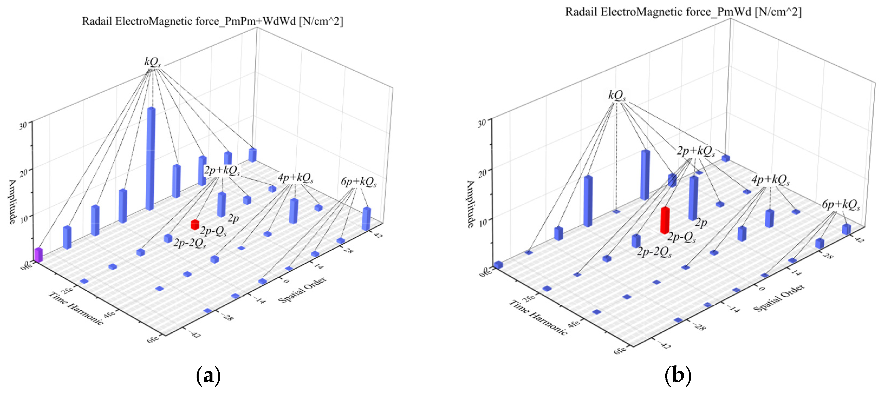
For DTP FSCW PM machines with 12s10p configuration and 12s14p configuration, the winding MMF spatial orders v are given by v = p + k Q s . For concise expression, the notation ( x , y ) is used to represent the harmonic components with spatial order x and temporal harmonic y. According to (10) and (11), the airgap force components follow the 2 n p + k Q s ,   2 n f e order–frequency relationship. Table 1 shows all the deduced airgap force components.
Components independently generated by PM and armature fields exhibit initial phases of 0 or π , corresponding to the real components of the airgap force complex Fourier series (Figure 2a), while components generated by the interaction of PM and armature fields show ± π / 2 phases, corresponding to the imaginary components (Figure 2b). The second order ( 2 p Q s ) components (red highlighted in Figure 2) are considered to be the most significant contributors to vibration and mainly come from the following.
  • The interaction between PM’s pth-order field and armature’s slot harmonic component p Q s .
  • Stator permeance modulation of 2p-order forces (from PM/winding self/interaction effects) generating lower-order 2 p Q s components.

3.2. Yoke Forces and Tooth Modulation Coefficients

As expressed in Section 2, distributed forces can be equivalently represented as concentrated forces [20,21]. For convenience of harmonic analytical analysis, taking a vth order radial airgap force with 2 f e electrical frequency v , 2 f e as an example and neglecting the curvature effects of the tooth structure, the resulting radial tooth concentrated forces (1) become
F v n = r g θ n τ θ n + τ f v cos v θ 2 ω e t ϕ d θ = r g 2 sin v τ v f v cos v θ n 2 ω e t ϕ ,
where 2 τ denotes the integration region of the tooth, ϕ is the initial phase.
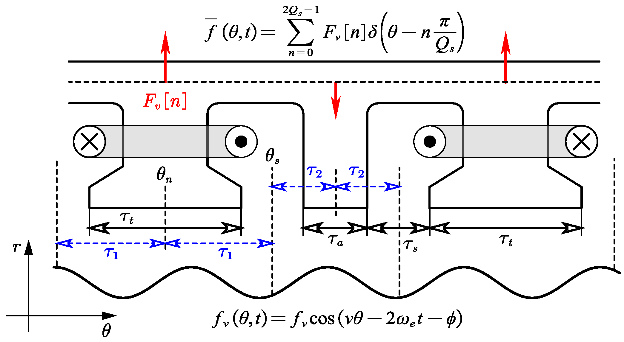
For the stator with auxiliary teeth shown in Figure 3, the stator tooth axis positions satisfy θ n = π n / Q s , where Q s stands for the number of wound teeth (auxiliary teeth excluded). Slot opening width is depicted by τ s , and τ a , τ t are the widths of wound teeth and auxiliary teeth, respectively. Two integration regions exist for concentrated forces: 2 τ 1 for wound teeth and 2 τ 2 for auxiliary teeth, with the following relationship:
2 τ 1 + 2 τ 2 = 2 π / Q s .
As described in (5) in Section 2, the concentrated forces are pulse trains with π / Q s spacing acting on the yoke:
f ¯ θ , t = n = 0 2 Q s 1 F v n δ θ n π Q s .
The Fourier series of (14) are
Y i = 1 2 π 0 2 π f ¯ θ , t e j i θ d θ = 1 2 π n = 0 2 Q s 1 F v n e j i n π Q s = r g Q s f v 2 π v sin v τ 1 + e j k π sin v τ 2 e j 2 ω e t j ϕ , i = v k Q s , r g Q s f v 2 π v sin v τ 1 + e j k π sin v τ 2 e j 2 ω e t + j ϕ , i = k Q s v .
With the transmission through stator teeth, the vth-order airgap force not only induces its inherent spatial order but also generates additional spatial orders in the stator yoke. These additional forces are called tooth modulation forces, whose spatial order i satisfies the relationship i = v k Q s (where k Z , an arbitrary integer). Therefore, the force density form of the ith-order yoke force can be expressed as
f ¯ i θ , t = Y i e j i θ + Y i e j i θ = r g Q s sin v τ 1 + 1 k sin v τ 2 π v f v cos ( i θ 2 ω e t ϕ ) .
Compared with the ith-order modulated force (16) and the original airgap force, the tooth modulation effect can be expressed by the modulation coefficient K i , v :
K i , v = r g Q s π sin v τ 1 + 1 k sin v τ 2 v , i = v k Q s .
The tooth modulation coefficient represents the amplitude and phase relationship between the vth-order airgap force f v θ , t and the modulated ith-order yoke force f ¯ i θ , t . Under a specific airgap force order v , the tooth modulation coefficient varies with the slot pitch 2 τ 1 of wound teeth in a trigonometric pattern. For given slot pitches, 2 τ 1 and 2 τ 2 , the tooth modulation coefficient changes with airgap force order v for a sinc function profile. In the special case that τ 1 = π / Q s ,   τ 2 = 0 , the stator becomes the traditional equal-teeth and double layer winding machine. The tooth modulation coefficient of the traditional equal-teeth geometry is
K i , v = r g sin v π / Q s v π / Q s , i = v k Q s .

4. Auxiliary Teeth Impact Analysis and Vibration Optimization

According to the analysis in Section 3, the second-order yoke force in 2 p = Q s ± 2 FSCW-PM machines can be concluded as
f ¯ 2 nd K 2 , 2 F 2 p Q s λ 0 Caused by   p pm   and   p Q s wd + K 2 , 2 F 2 p λ s 1 Permeance modulated + K 2 , 2 p F 2 p λ 0 Tooth modulated .
where the slot harmonic force, permeance-modulated force and tooth modulated force are related to auxiliary teeth structural parameters.

4.1. Influence of Auxiliary Teeth on Winding MMF and Stator Permeance

The pitch factor sin v τ in the winding MMF (8) directly related to the coil span 2 τ . For FSCW-PM machines with auxiliary teeth, the coil span is the slot pitch 2 τ 1 of the wound-tooth and varies simultaneously with the auxiliary teeth slot pitch 2 τ 2 . Their variation satisfies the relationship in (13). The normalized amplitude variations in fundamental and low-order slot harmonics in winding MMF for 12s10p and 12s14p DTP machines are presented in Figure 4a. As the slot pitch 2 τ 1 decreases, the 7th-order winding MMF initially increases, reaches maximum at 2 τ 1 = π / p ( 25.7 ° ), then decreases, while the 5th-order amplitude exhibits a monotonically decreasing trend. For 12s10p machine, the fundamental winding MMF corresponds to v = 5 , with the low-order slot harmonics at p + k Q s = 7 , 17 , 19 ; for the 12s14p machine, the fundamental is v = 7 , and low-order slot harmonics are p + k Q s = 5 , 17 , 19 . Therefore, an optimized auxiliary teeth width can suppress slot harmonics (5th, 17th, and 19th orders) of the 12s14p machines, and thus the slot harmonic force in (19), while maintaining or enhancing the fundamental MMF.
The permeance of the stator with auxiliary teeth satisfies the following relationship:
λ s k Q s 2 π τ t / 2 τ t / 2 e j k Q s θ d θ + π / Q s τ a / 2 π / Q s + τ a / 2 e j k Q s θ d θ = 2 k π cos k Q s τ 1 sin k Q s τ s 2 .
By fixing the slot opening τ s , the variations in permeance harmonics (tooth-number order and double-tooth-number order) versus the wound tooth slot pitch 2 τ 1 are shown in Figure 4b. As 2 τ 1 decreases from π / Q s = 30 ° , the tooth-order permeance harmonics exhibit a decreasing trend and become zero at 2 τ 1 = 15 ° , where the widths of auxiliary teeth and wound teeth are equal.

4.2. Influence of Auxiliary Teeth on Tooth Modulation Effect

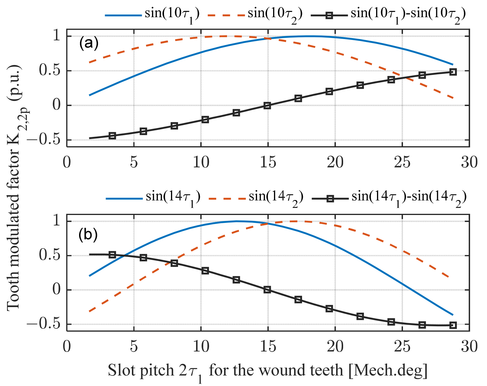
In actual machines, the wound tooth is wider than the auxiliary tooth ( 2 τ 1 > 2 τ 2 ). For the 2 p -order airgap force, the sign of the tooth modulation coefficient K 2 , 2 p ( v = 2 p ,   i = 2   a n d   k = 1 in (17)) satisfies the following relationship:
K 2 , 2 p < 0 , 2 p = Q s + 2 . K 2 , 2 p > 0 , 2 p = Q s 2 .
Detailed proof of (21) is provided in Appendix A. The phase of the modulated second-order force remains consistent with that of the original 2p airgap force when the tooth modulation coefficient K 2 , 2 p > 0 , but exhibits a 180-degree phase shift when K 2 , 2 p < 0 . The variation trends of the tooth modulation coefficient K 2 , 2 p with slot pitch 2 τ 1 in 12s10p and 12s14p machines are shown in Figure 5. A few values of K 2 , 2 p in (17) are shown in Table 2. Results show that the tooth modulation coefficient K 2 , 10 > 0 for 12s10p machine when 2 τ 1 > 2 τ 2 ( 2 τ 1 > 15 ° ), and K 2 , 14 < 0 for 12s14p machine. These trends are consistent with the relationship in (21).
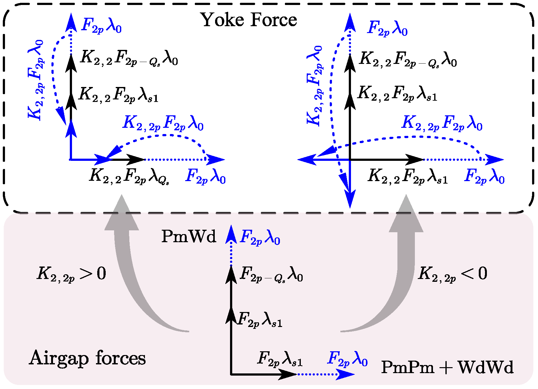
According to (6), the 2 p and 2 p Q s order airgap forces from the interaction between the pth-order PM field and p , p Q s th order armature field are phase-synchronized. In addition, according to (20), the tooth number permeance λ s 1 > 0 , which means that the permeance-modulated force F 2 p λ s 1 aligns with the 2p-order force F 2 p λ 0 as shown in Figure 6. For 2 p = Q s + 2 machines, the tooth modulation coefficient K 2 , 2 p < 0 results in the tooth-modulated force K 2,2 p F 2 p λ 0 suppressing both permeance-modulated force K 2 , 2 F 2 p λ s 1 and slot harmonic force K 2 , 2 F 2 p Q s λ 0 . Conversely, 2 p = Q s 2 machines with K 2 , 2 p > 0 exhibit force enhancement.

4.3. Vibration Mitigation Method

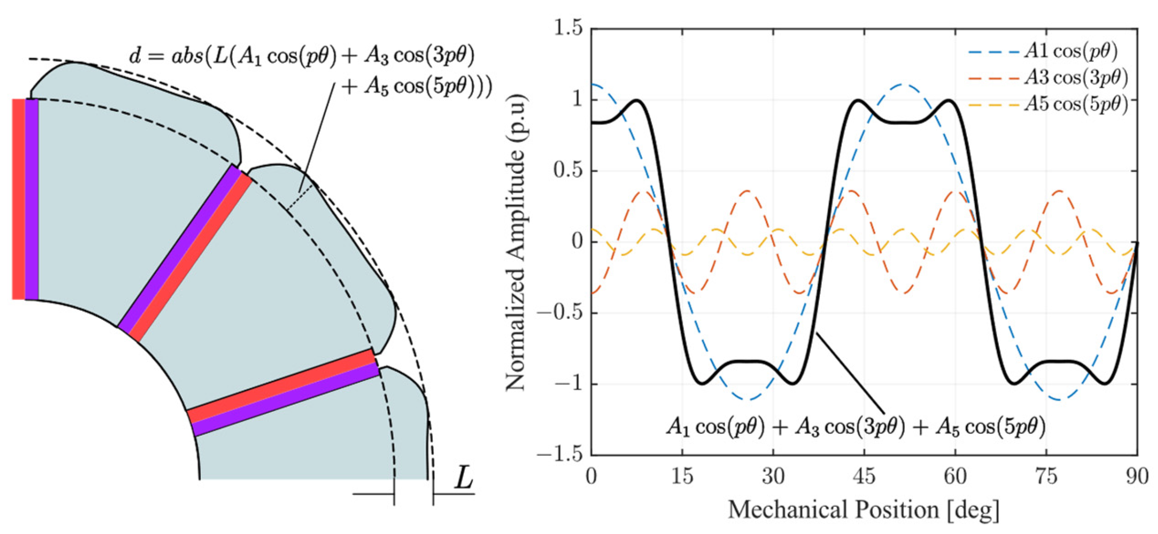
This section therefore focuses on vibration optimization for 12s14p machines. As discussed in Section 4.2, optimal auxiliary teeth width and enhancement of 2p-order airgap force can effectively suppress second-order electromagnetic vibrations. For spoke-type PM machines, adjusting the rotor magnetic pole shape modifies the p, 3p, and 5p airgap magnetic harmonics, thereby adjusting the 2p-order electromagnetic force. The thickness of the magnetic pole is defined as
d = abs L A 1 cos p θ + A 3 cos 3 p θ + A 5 cos 5 p θ .
where L denotes the max thickness of the magnetic pole, A 1 , A 3 , A 5 represent the amplitudes of the injected 1st, 3rd, and 5th harmonics, respectively, as shown in Figure 7.
Structural parameters (auxiliary teeth width A t , slot opening S o , injected harmonic amplitudes A 1 , A 3 , A 5 ) are difficult to optimize theoretically. Thus, a multi-objective NSGA-III algorithm is employed to maximize torque, minimize 2nd- and 4th-order forces, and determine the optimal parameter combination. To satisfy the winding coil placement requirements and ensure the structural rigidity of auxiliary teeth, the optimization objectives and constraints are formulated as follows:
Function : Min   f 1 f 2 n d , Min   f 2 f 4 t h , Max   f 3 T o u t , Constraints : S o > 2 mm , A t > 2 mm ; A 1 [ 1 , 1.5 ] , A 2 [ 0 , 0.8 ] , A 5 [ 0.1 , 0.15 ] ; max ( d ) L .
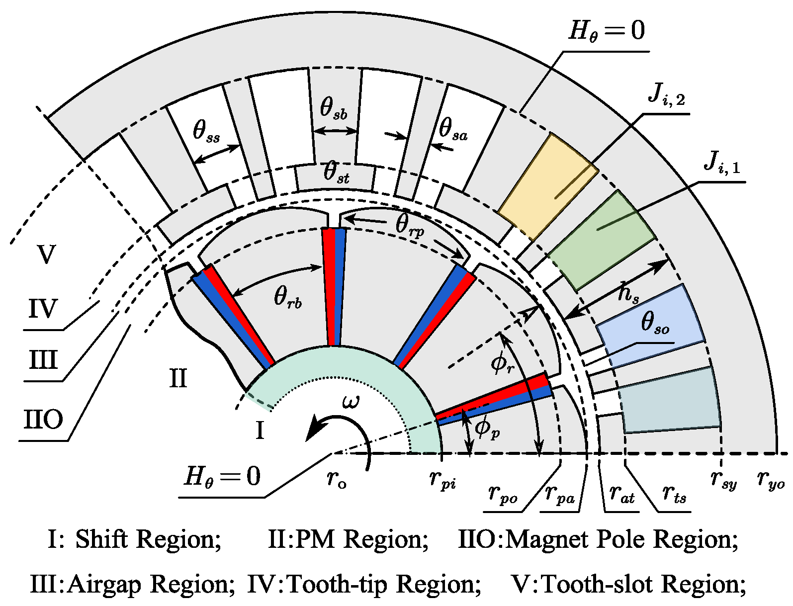
Since genetic algorithm optimization explores the Pareto front through population-based crossover/mutation operations, requiring intensive magnetic field computations. Thus, this study employs the semi-analytical dimension-reduced harmonic modeling (DRHM) method in [23] for rapid magnetic field calculations. The simplified machine topology is shown in Figure 8, and the non-optimized structural parameters detailed in Table 3. The number of coil turns of the winding is designed to be 15, and the rated operating current is 12 Arms. The motor is driven by the i d = 0 control strategy and the rotating velocity is 1200 Rpm.
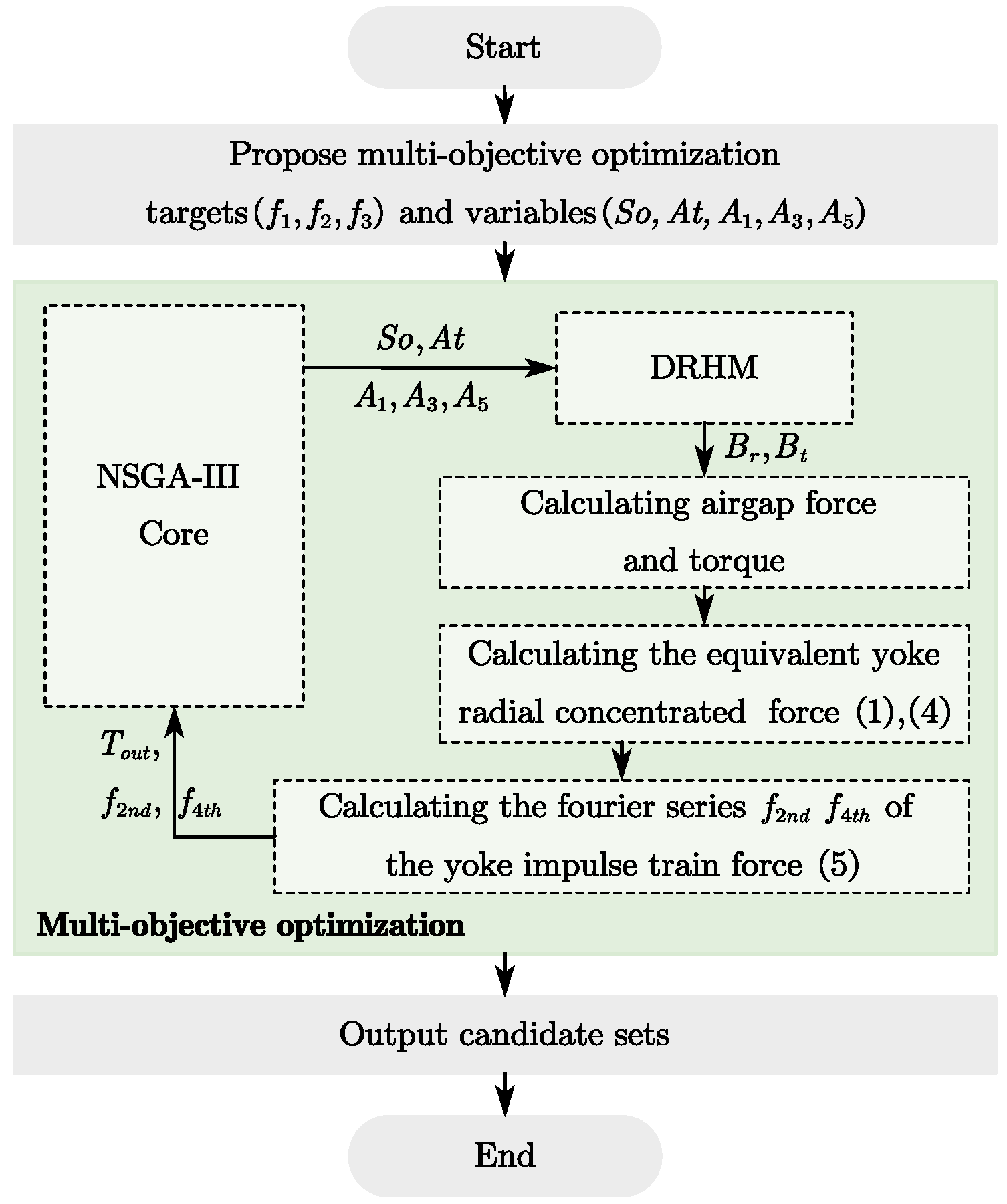
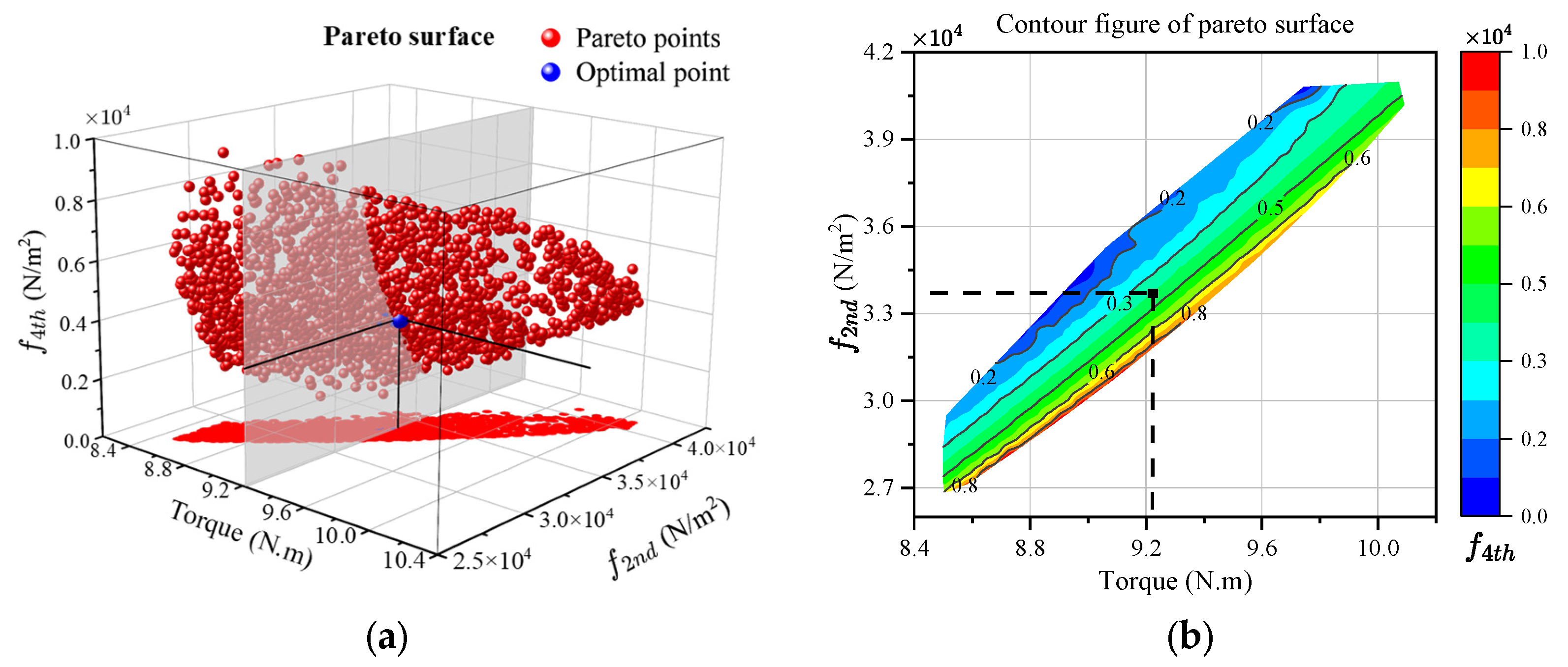
The parameter optimization process is shown in Figure 9, the DRHM calculates the airgap flux density components ( B r , B t ) for each candidate design generated by NSGA-III, which varies the slot opening ( S o ), auxiliary tooth width ( A t ), and injected harmonic amplitudes ( A 1 , A 3 , A 5 ). Based on the airgap flux density, the motor’s torque and the amplitudes of 2nd- and 4th-order radial force components ( f 2 n d ,   f 4 t h ) are derived according to the precise yoke forces (1), (4), and (5) described in Section 2. NSGA-III performs non-dominated sorting of the results, yielding a set of candidate solutions (red points in Figure 10a), whose surface forms the Pareto front.
As evident from Figure 10, a mutually constrained relationship exists among the second-order force ( f 2 n d ), fourth-order force ( f 4 t h ), and output torque ( T o u t ). Therefore, a compromise between torque performance and vibration mitigation is essential. For a comparative analysis with conventional equal teeth machines, structural parameters are chosen under equivalent output torque conditions. The conventional design in Table 3 has a peak torque of 9.2 N∙m at a slot opening width ( S o = 5   mm ), serving as a benchmark for parametric optimization. Through compromising between f 2 n d and f 4 t h forces, the structural parameters corresponding to the blue data point in Figure 10a are selected as the optimized design, with the following specifications: S o = 2.0   mm , A t = 2.5   mm , A 1 = 1.079 , A 3 = 0.212 , and A 5 = 0.036 .

5. Optimal Design Verification Via Finite Element Analysis

To validate the effects of auxiliary tooth and rotor pole shape optimization on both output performance and electromagnetic vibration in 2 p = Q s + 2 type machines as discussed in Section 4, this section established 2D electromagnetic and structural vibration simulation models for a 12s14p spoke-type DTP-PM motor on the ANSYS, as shown in Figure 11. In Maxwell 2D simulations, the airgap forces are calculated as concentrated forces and bending moments that act on the center of each tooth surface. Subsequently, the temporal harmonics of the concentrated forces and bending moments are transferred to ANSYS Mechanical as vibrational excitation for structural vibration response calculation.
The simulation models include (a) Maxwell2D models which include three configurations: stator with traditional equal teeth and rotor pole sine-shaped (TraTooth + SinePole), stator with auxiliary teeth and rotor pole sine-shaped (AuxTooth + SinePole), and stator with auxiliary teeth and rotor pole profile harmonic injection (AuxTooth + HarInject); (b) Structural vibration models include stator with traditional equal teeth and stator with auxiliary teeth. The differences in parameter values among the three configurations are listed in Table 4.
The structural vibration simulation model comprises the housing and stator. Fixed constraints are applied to the blue positioning holes at both housing ends, and a tied connection is established between housing and stator. Windings are modeled as additional mass on stator teeth, and the stator laminations could be replaced by a solid with orthotropic elastic parameters [24]. The material parameters are listed in Table 5, where ρ is the mass density; E r , E t , and E z are Young’s modulus in radial, tangential and axial directions, respectively. ν r t , ν r z , and ν t z are Poisson’s ratios in the direction of r t , r z , and t z , respectively. As shown in Table 6, nature frequencies of stators with auxiliary teeth are lower than those of traditional stators. These frequency shifts are caused by the increased mass due to the auxiliary teeth and may result in a higher vibration response under the same force.

5.1. Comparison of Electromagnetic Performance

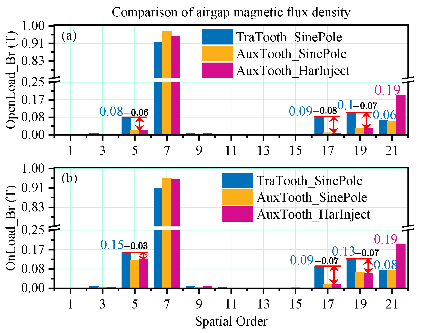
The airgap flux density harmonics of the three types of motors under open load and rated load are shown in Figure 12. As shown in Figure 12a, the application of the auxiliary teeth reduced the permeance of tooth-number and double tooth-number orders, leading to 75%, 89% and 70% reductions in the 5th-order ( p Q s ), 17th-order ( p 2 Q s ), and 19th-order ( p + Q s ) harmonics, respectively. The increase in pth order airgap flux density is caused by the increase in zero-order permeance and pth-order winding MMF. Following the injection of 3rd and 5th spatial harmonics into the magnetic pole profile, the 3p-order airgap magnetic flux density harmonics exhibit approximately threefold amplification. Compared to the open load condition, the 5th-order harmonic amplitude in Figure 12b demonstrates a significant increase under the rated load due to the presence of ( p Q s ) winding slot harmonic.
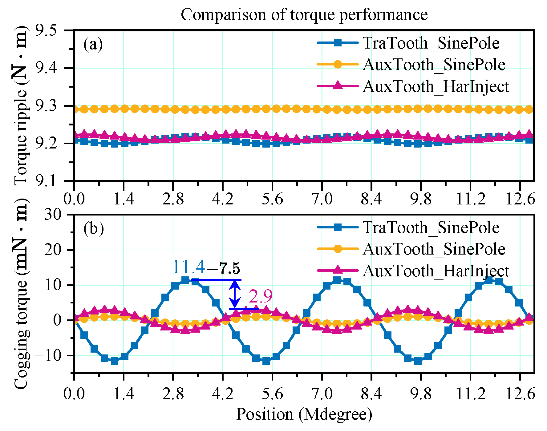
The influence of the auxiliary teeth and rotor pole profile harmonic injection on both motor output torque and cogging torque is illustrated in Figure 13. The standalone auxiliary teeth configuration improved the average output torque due to the enhanced fundamental magnetic flux density. However, the application of rotor pole profile harmonic injection led to an increase in 3p-order harmonic magnetic flux density, which reduced the average output torque.
The cogging torque satisfies the following relationship:
T c = R 2 L c o r e μ 0 0 2 π B r B t d θ λ 0 λ s k sin 2 n ω e t , when   2 n p k Q s = 0 .
The cogging torque is related to the stator permeance, and the primary part is obtained when k = 7 and n = 6 . According to (20), λ s k = 0 when mod k Q s τ 1 , π = π / 2 , indicating that the cogging torque becomes zero. In the optimal design, S o = 2   mm , A t = 2.5   mm , 2 τ 1 = 23.55 ° , and λ s 7 0 . Thus, as shown in Figure 13b, after applying auxiliary teeth, the cogging torque amplitude decreased from 11.4 mN·m to 2.9 mN·m, achieving a 74.6% amplitude reduction.

5.2. Comparison of Electromagnetic Force and Vibration Response

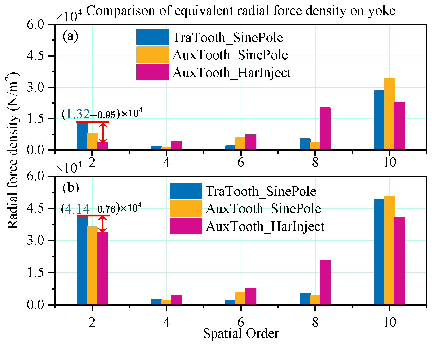
The harmonic components of equivalent yoke force for three configurations under both open-load and rated-load conditions are comparatively presented in Figure 14. Through the synergistic application of auxiliary teeth and rotor pole profile harmonic injection, the second-order electromagnetic force components are both reduced, specifically, from 4.14 × 10 4 N/m2 to 3.38 × 10 4 N/m2 under rate load (phase current 12 Arms and load angle 90 ° , i.e., i d = 0 ), representing an approximate 18% reduction. Although the 4th-, 6th-, and 8th-order components exhibit increases in magnitude, their higher spatial orders result in a limited amplitude growth of electromagnetic vibration response.
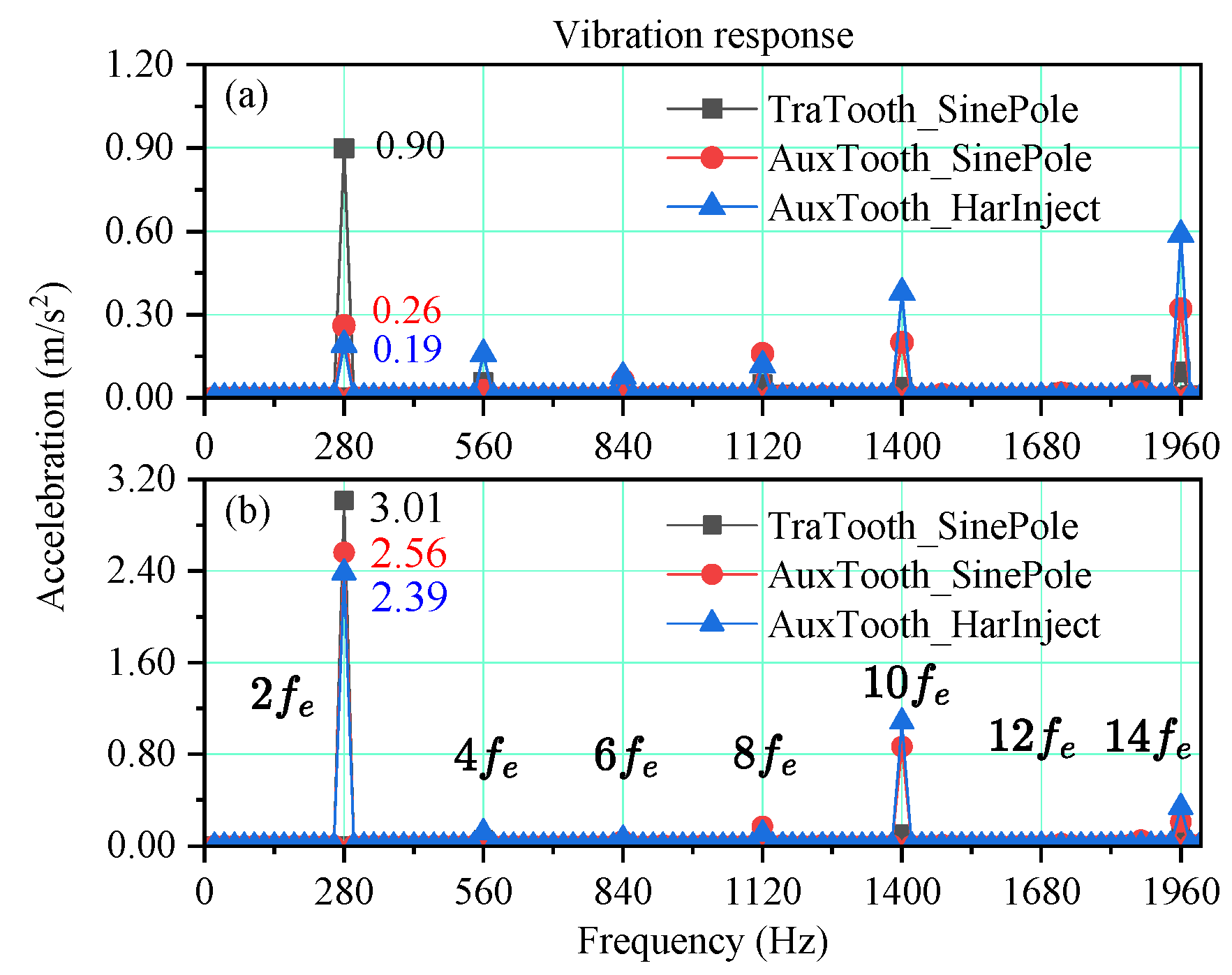
The vibration response amplitudes at different positions on the motor surface differ. Thus, a fixed measurement point (black triangle in Figure 11b) is selected for comparing the trends of the three configurations. Radial vibration acceleration responses under open-load and rated-load conditions are shown in Figure 15. At a mechanical speed of 1200 rpm, the second-order electromagnetic force rotating at twice the electrical frequency ( 2 f e = 280 Hz) dominates the vibration spectrum. The vibration response trends of the three configurations match the electromagnetic force magnitude variations as shown in Figure 14. Compared to the conventional structure, the synergistic application of auxiliary teeth and rotor profile harmonic injection reduces the second-order electromagnetic vibration acceleration under a rated load (from 3.01 m/s2 to 2.39 m/s2), with a 21% amplitude reduction.
The amplitude of vibration responses under multi-speed and Campbell diagram of the equivalent radiated power levels from 900 to 1500 rpm are shown in Figure 16. Except for the main vibrations at frequencies 2 f e , 4 f e , 6 f e , and 10 f e , resonance appears around 2067 Hz (elliptical marked) which is the 2nd-order natural frequency of the structure.

6. Conclusions

This study has analyzed the effects of auxiliary teeth on FSCW-PM machines with 2 p = Q s ± 2 slot–pole combinations through three key aspects: winding MMF, stator permeance, and tooth force modulation effect. The auxiliary teeth have been shown to effectively reduce slot-order permeance harmonics and suppress electromagnetic forces caused by permeance modulation. For 2 p = Q s ± 2 configurations, optimized auxiliary teeth width has demonstrated the ability to mitigate slot harmonics without sacrificing fundamental MMF amplitude.
Furthermore, based on the equivalent yoke force model, tooth modulation coefficients for airgap electromagnetic forces have been established. Comparative analysis reveals distinct modulation effects in 2 p = Q s ± 2 machines:
  • For 2 p = Q s 2 configurations, the tooth modulation coefficient K 2 , 2 p > 0 , where 2p-order airgap forces enhance second-order electromagnetic vibrations;
  • In 2 p = Q s + 2 machines, K 2 , 2 p < 0 , resulting in 2p-order forces suppressing second-order vibrations.
Based on these characteristics, this study proposes a synergistic approach utilizing optimal auxiliary teeth width and rotor pole profile harmonic injection to further optimize electromagnetic vibrations in 2 p = Q s + 2 spoke-type machines. The NSGA-III genetic algorithm was employed to obtain the optimal Pareto front for three key parameters: auxiliary tooth width, slot opening width, and rotor pole harmonic injection coefficients. With optimized parameters, the cogging torque and second-order electromagnetic vibrations were reduced by 74.6% and 21%, respectively, while maintaining uncompromised output torque.
The core of this method lies in utilizing the characteristic that the slot pitch of the motor with 2 p = Q s + 2 is larger than the pole pitch, as well as the suppression effect of the 2p-order airgap electromagnetic force on the 2nd-order yoke force through the tooth modulation effect. Therefore, this method is valid for other 2 p = Q s + 2 FSCW tooth coil motors. The method proposed in this paper verifies the trends in vibration variation before and after optimization through simulations. However, the auxiliary tooth may also reduce the slot area and increase the slot filling, which may, in turn, impact mechanical performance. Moreover, there are still some differences between the simulation model and actual motor, such as the neglected endcap and the simplified connection between housing and stator core. Therefore, further experimental verification is still necessary and will be one of the follow-up research directions from this paper.

Author Contributions

H.Z. wrote this manuscript; W.W. proposed the methodology and conceptualization; X.L. reviewed and edited this manuscript; Z.W. was responsible for the funding acquisition. All authors have read and agreed to the published version of the manuscript.

Funding

This research was funded by: (1) The National Natural Science Foundation of China, grant number 52477060 and 52077155; (2) The Shandong Provincial Technology Innovation Guidance Program, grant number YDZX2024097.

Data Availability Statement

The original contributions presented in this study are included in the article. Additionally, the NSGA-III software is openly available in https://github.com/lfarizav/NSGA-III (accessed on 15 May 2024). Any questions about the DRHM method or further inquiries can be directed to the corresponding author.

Conflicts of Interest

The authors declare no conflicts of interest. The funders had no role in the design of the study; in the collection, analyses, or interpretation of data; in the writing of the manuscript; or in the decision to publish the results.

Nomenclature

f r Radial airgap force density [ N / m 2 ]. p Pole pairs
f t Tangential airgap force density [ N / m 2 ]. Q s Slot number
f ¯ y r Radial force density on yoke [ N / m 2 ]. θ n Position of the nth tooth.
r g Radius of airgap central circle [m]. Δ θ Slot pitch of the tooth.
r y Radius of yoke central circle [m]. τ 1 Slot pitch of wound teeth.
F r n Radial concentrated forces [N/m]. τ 2 Slot pitch of auxiliary teeth.
F t n Tangential concentrated forces [N/m]. τ a Auxiliary teeth width.
M n Bending moments on tooth shoulder. τ t Wound teeth width.
M y n Bending moments on yoke. τ s Slot opening width.
F M n Equivalent forces by M y n .mWinding phases number.
F M r n Equivalent radial forces by M y n . λ Airgap permeance.
λ s k k Q s -th order stator permeance. ω e Electrical angular velocity.
λ r n 2 n p -th order rotor permeance. f e Electrical frequency.

Appendix A

Appendix A.1. Proof of Equation Q s / G C D 2 p , Q s = m k , k Z

The greatest common divisor of slot and pole numbers G C D 2 p , Q s can be calculated by:
Q s 2 p = Q 0 N t 2 p 0 N t .
where N t = G C D p , Q s is the number of unit motors, Q 0 , p 0 are slots and pole-pairs number of the unit motor, respectively. Then, GCD 2 p , Q s satisfies:
GCD 2 p , Q s = N t , Q 0 is odd , 2 N t , Q 0 is even .
Obviously, when Q 0 is odd,
Q s GCD 2 p , Q s = Q 0 = m k ,
where k is an integer. When Q 0 is even, for the symmetrical winding, Q 0 = 2 m k is existing, thus:
Q s GCD 2 p , Q s = Q 0 2 = m k .
According to (A3) and (A4), the relationship Q s / G C D 2 p , Q s = m k is established.

Appendix A.2. Proof of Equation G C D 2 p , Q s = 2 p / d

The number of slots per pole per phase q can be expressed by:
q = Q s 2 m p = Q s / m 2 p = N t d t ,
where t is calculated by:
t = 2 p d = GCD 2 p , Q s m .
According to the proof in Appendix A.1, for a machine with symmetrical winding, it holds that:
GCD 2 p , Q s m = GCD 2 p , k GCD 2 p , Q s GCD 2 p , Q s .
And due to,
GCD 2 p , Q s m GCD 2 p , Q s .
Thus, according to (A5)–(A8),
2 p d = GCD 2 p , Q s m = GCD 2 p , Q s .

Appendix A.3. Sign Derivation of Tooth Modulation Coefficient K 2,2 p

According to (13) and (17), tooth modulation coefficient K 2,2 p satisfies the following relationship:
K 2 , 2 p sin 2 p τ 1 sin 2 p τ 2 2 cos p π Q s sin 2 p τ 1 p π Q s
Since the relationship of poles and slots 2 p = Q s ± 2 , (A10) can be rewritten as
K 2 , 2 p sin π Q s cos 2 p τ 1 π Q s , 2 p = Q s + 2 sin π Q s cos 2 p τ 1 + π Q s , 2 p = Q s 2
Obviously, sin π / Q s > 0 is true. In general, the slot pitch 2 τ 1 of wound-tooth satisfies the following relationship:
π Q s < 2 τ 1 and 2 τ 1 < 2 π Q s .
Thus,
π 2 < 2 p τ 1 π Q s < π + 2 π Q s , 2 p = Q s + 2 π 2 < 2 p τ 1 + π Q s < π 2 π Q s , 2 p = Q s 2
The slot number of three-phase 2 p = Q s ± 2 FSCW-PM machines satisfy Q s 6 , then, π 2 π / Q s lies in the second quadrant and π + 2 π / Q s lies in the third quadrant. Therefore,
cos 2 p τ 1 π / Q s < 0 , 2 p = Q s + 2 cos 2 p τ 1 + π / Q s < 0 , 2 p = Q s 2
According to (A11)–(A14), the following relationship is valid:
K 2 , 2 p < 0 , 2 p = Q s + 2 K 2 , 2 p > 0 , 2 p = Q s 2

References

  1. Hua, Y.; Wang, C.; Liu, Y.; Zhang, Z.; Kong, X.; Han, J. Comparative Study of High Torque Density Spoke-Type PM In-Wheel Motors for Special Vehicle Traction Applications. IEEE Trans. Ind. Appl. 2022, 58, 1952–1962. [Google Scholar] [CrossRef]
  2. Zou, J.; Liu, M.; Xu, Y.; Yu, G.; Lan, H. Vibration Contribution Analysis of Radial and Tangential Electromagnetic Force Harmonic of Permanent Magnet Synchronous Motor. IEEE Trans. Appl. Supercond. 2024, 34, 5207605. [Google Scholar] [CrossRef]
  3. Guo, L.; Xu, J.; Wu, S.; Xie, X.; Wang, H. Analysis and Design of Dual Three-Phase Fractional-Slot Permanent Magnet Motor with Low Space Harmonic. IEEE Trans. Magn. 2022, 58, 8100112. [Google Scholar] [CrossRef]
  4. Kim, J.-H.; Won, Y.-J.; Lim, M.-S. Analysis and Reduction of Radial Vibration of FSCW PMSM Considering the Phase of Radial, Tangential Forces and Tooth Modulation Effect. IEEE Trans. Transp. Electrif. 2024, 11, 2976–2987. [Google Scholar] [CrossRef]
  5. Zhu, S.; Zhao, W.; Ji, J.; Liu, G.; Lee, C.H.T. Design to Reduce Modulated Vibration in Fractional-Slot Concentrated-Windings PM Machines Considering Slot–Pole Combination. IEEE Trans. Transp. Electrif. 2023, 9, 575–585. [Google Scholar] [CrossRef]
  6. Xu, Z.; Shi, D.; Gu, D.; Liu, Z.; Chen, G.; Hu, C.; Sun, X.; Sun, P.; Zhu, B. Innovative approach to mitigating vibration and noise in an external rotor permanent magnet synchronous motor. J. Vib. Control. 2024, 57, 1–18. [Google Scholar] [CrossRef]
  7. Zhao, W.; Zheng, J.; Ji, J.; Zhu, S.; Kang, M. Star and Delta Hybrid Connection of a FSCW PM Machine for Low Space Harmonics. IEEE Trans. Ind. Electron. 2018, 65, 9266–9279. [Google Scholar] [CrossRef]
  8. Zhao, B.; Gong, J.; Tong, T.; Xu, Y.; Semail, E.; Nguyen, N.-K.; Gillon, F. A Novel Five-Phase Fractional Slot Concentrated Winding with Low Space Harmonic Contents. IEEE Trans. Magn. 2021, 57, 8104605. [Google Scholar] [CrossRef]
  9. Wu, Z.; Fan, Y.; Lee, C.H.; Gao, D.; Yu, K. Vibration Optimization of FSCW-IPM Motor Based on Iron-Core Modification for Electric Vehicles. IEEE Trans. Veh. Technol. 2020, 69, 14834–14845. [Google Scholar] [CrossRef]
  10. Zhu, S.; Ji, N.; Zhao, W.; Zheng, J.; Mao, Y.; Liu, G. Unequal Teeth Design to Reduce Electromagnetic Vibration in Fractional-Slot Concentrated-Windings Permanent-Magnet Machine. J. Magn. 2019, 24, 657–667. [Google Scholar] [CrossRef]
  11. Wu, M.; Zhao, W.; Ji, N.; Zheng, J.; Luo, J. Reduction of Tooth Harmonic in Fractional-Slot Concentrated-Winding Permanent-Magnet Machines Using New Stator Design. J.Magn. 2018, 23, 218–228. [Google Scholar] [CrossRef]
  12. He, Y.; Zhao, W.; Tang, H.; Ji, J. Auxiliary teeth design to reduce short-circuit current in permanent magnet generators. Trans. Electr. Mach. Syst. 2020, 4, 198–205. [Google Scholar] [CrossRef]
  13. Fang, H.; Li, D.; Qu, R.; Yan, P. Modulation Effect of Slotted Structure on Vibration Response in Electrical Machines. IEEE Trans. Ind. Electron. 2019, 66, 2998–3007. [Google Scholar] [CrossRef]
  14. Zhu, S.; Zhao, W.; Ji, J.; Liu, G.; Mao, Y.; Liu, T. Investigation of Bread-Loaf Magnet on Vibration Performance in FSCW PMSM Considering Force Modulation Effect. IEEE Trans. Transp. Electrif. 2021, 7, 1379–1389. [Google Scholar] [CrossRef]
  15. Zhao, W.; Zhu, S.; Ji, J.; Liu, G.; Mao, Y. Analysis and Reduction of Electromagnetic Vibration in Fractional-Slot Concentrated-Windings PM Machines. IEEE Trans. Ind. Electron. 2022, 69, 3357–3367. [Google Scholar] [CrossRef]
  16. Kim, J.-H.; Park, S.-H.; Ryu, J.-Y.; Lim, M.-S. Comparative Study of Vibration on 10-Pole 12-Slot and 14-Pole 12-Slot PMSM Considering Tooth Modulation Effect. IEEE Trans. Ind. Electron. 2023, 70, 4007–4017. [Google Scholar] [CrossRef]
  17. Kim, J.-H.; Ryu, J.-Y.; Park, S.-H.; Cha, K.-S.; Won, Y.-J.; Park, C.-S.; Lim, M.-S. Investigation on Radial Vibration of FSCW PMSM According to Pole/Slot Combination Considering Phase of Radial, Tangential Force and Moment. IEEE Trans. Ind. Appl. 2024, 60, 439–449. [Google Scholar] [CrossRef]
  18. Liang, W.; Wang, J.; Luk, P.C.-K.; Fei, W. Analytical Study of Stator Tooth Modulation on Electromagnetic Radial Force in Permanent Magnet Synchronous Machines. IEEE Trans. Ind. Electron. 2021, 68, 11731–11739. [Google Scholar] [CrossRef]
  19. Pile, R.; Devillers, E.; Le Besnerais, J. Comparison of Main Magnetic Force Computation Methods for Noise and Vibration Assessment in Electrical Machines. IEEE Trans. Magn. 2018, 54, 8104013. [Google Scholar] [CrossRef]
  20. Andreou, P.; Hajjaj, A.Z.; Mohammadpour, M.; Theodossiades, S. Analytical Multiphysics Methodology to Predict Vibroacoustics in PMSMs Combining Tangential Electromagnetic Excitation and Tooth Modulation Effects. IEEE Trans. Transp. Electrif. 2024, 10, 5997–6009. [Google Scholar] [CrossRef]
  21. Hong, J.; Gui, L.; Cao, J. Analysis and Experimental Verification of the Tangential Force effect on Electromagnetic Vibration of PM Motor. IEEE Trans. Energy Convers. 2023, 38, 1893–1902. [Google Scholar] [CrossRef]
  22. Fang, H.; Li, D.; Guo, J.; Xu, Y.; Qu, R. Hybrid Model for Electromagnetic Vibration Synthesis of Electrical Machines Considering Tooth Modulation and Tangential Effects. IEEE Trans. Ind. Electron. 2021, 68, 7284–7293. [Google Scholar] [CrossRef]
  23. Zhang, H.; Wang, W.; Li, X.; Wang, Z. Semi-Analytical Model for Spoke-Type PM Motor Nonlinear Magnetic Field Calculation with Irregular Magnetic Pole Shape. IEEE Trans. Magn. 2024, 60, 8204709. [Google Scholar] [CrossRef]
  24. Xing, Z.; Wang, X.; Zhao, W. Fast Calculation of Electromagnetic Vibration of Surface-Mounted PMSM Considering Teeth Saturation and Tangential Electromagnetic Force. IEEE Trans. Ind. Electron. 2023, 71, 316–326. [Google Scholar] [CrossRef]
Figure 1. Airgap force mapping model.
Machines 13 00867 g001
Figure 2. Radial airgap forces of 12s14p: (a) PmPm + WdWd; (b) PmWd.
Machines 13 00867 g002
Figure 3. Airgap force transformation in the stator with auxiliary teeth.
Machines 13 00867 g003
Figure 4. Influence of auxiliary teeth: (a) Winding MMF; (b) Stator permeance.
Machines 13 00867 g004
Figure 5. Variation in tooth modulation coefficient K 2,2 p with slot pitch: (a) 12s10p; (b) 12s14p.
Machines 13 00867 g005
Figure 6. Second-order phase relationship of 2 p = Q s ± 2 machines.
Machines 13 00867 g006
Figure 7. Harmonic injection of magnetic pole shape.
Machines 13 00867 g007
Figure 8. Spoke-type PM machine structure with auxiliary teeth.
Machines 13 00867 g008
Figure 9. Structure parameters based on multi-object optimization.
Machines 13 00867 g009
Figure 10. Results of multi-objective optimization: (a) Pareto surface; (b) Contour figure of pareto surface.
Machines 13 00867 g010
Figure 11. ANSYS simulation model: (a) Maxwell2D models; (b) Structural vibration simulation models for the traditional equal-teeth stator and the auxiliary teeth added stator.
Machines 13 00867 g011
Figure 12. Airgap radial flux density comparison: (a) Open load; (b) On load.
Machines 13 00867 g012
Figure 13. Torque performance comparison: (a) Output torque; (b) Cogging torque.
Machines 13 00867 g013
Figure 14. Comparison of equivalent yoke force density: (a) Open load; (b) On load.
Machines 13 00867 g014
Figure 15. Comparison of vibration response: (a) Open load; (b) On load.
Machines 13 00867 g015
Figure 16. Vibrations under multi-speed: (a) vibration amplitude; (b) Campbell diagram.
Machines 13 00867 g016
Table 1. The airgap forces of 12s10p and 12s14p DTP-PM machines.
λ 2 θ , t Pm-PmPm-WdWd-Wd
2 n p , 2 n f e 2 n p + k Q s , 2 n f e k Q s , 0 2 n p + k Q s , 2 f e
0 , 0 2 n p , 2 n f e 2 n p + k Q s , 2 n f e k Q s , 0 2 n p + k Q s , 2 f e
k Q s , 0 2 n p + k Q s , 2 n f e 2 n p + k Q s , 2 n f e k Q s , 0 2 n p + k Q s , 2 f e
2 n p , 2 n f e 2 n p , 2 n f e 2 n p + k Q s , 2 n f e 2 n p + k Q s , 2 n f e 2 n p + k Q s , 2 n f e
2 n p + k Q s , 2 n f e 2 n p + k Q s , 2 n f e 2 n p + k Q s , 2 n f e 2 n p + k Q s , 2 n f e 2 n p + k Q s , 2 n f e
Initial phase 0   o r   π ± π / 2 0   o r   π
Table 2. Values of K 2 , 2 p of the 12s10p and 12s14p spoke-type PM motors.
2 τ 1 5 ° 10152025
12s10p−0.006−0.003300.00330.006
Sign K 2 , 10 < 0 K 2 , 10 = 0 K 2 , 10 > 0
12s14p0.00520.00320−0.0032−0.0052
Sign K 2 , 14 > 0 K 2 , 14 = 0 K 2 , 14 < 0
Table 3. Parameters of the 12s14p spoke-type PM motor.
ParametersValuesParametersValues
r y o (mm)62Tooth Height h s 16 mm
r s y (mm)56Tooth body width 12 A t mm
r t s (mm)43Rotor Opening2 mm
r a t (mm)40Rotor Insert (L)1.5 mm
r p a (mm)39PM Insert1.5 mm
r p o (mm)37.5PM Length15 mm
r p i (mm)22.5PM Thickness2.5 mm
B r e   T 1.395Axial Length80 mm
Table 4. Design parameters of the three types of motors.
ParametersTraTooth
+ SinePole
AuxTooth
+ SinePole
AuxTooth
+ HarInject
Slot open width S o (mm)522
Auxiliary teeth width A t (mm)-2.52.5
Magnet poles inset L (mm)1.51.51.5
Magnet pole shape parameters A 1 --1.079
A 3 --−0.212
A 5 --0.036
Table 5. Material parameters.
NameParametersEquivalent StatorHousing
Mass density ρ   ( k g / m 3 ) 73722770
Young’s modulus E r , E t (GPa)19471
E z (GPa)67.371
Shear modulus G r t (GPa)74.6526.7
G r z , G t z (GPa)25.926.7
Poisson’s ratio ν r t , ν r z , ν t z 0.30.33
Table 6. Modal shapes and nature frequencies.
Modal Order234
Traditional teethMachines 13 00867 i001Machines 13 00867 i002Machines 13 00867 i003
Nature frequency2091 Hz3056 Hz4854 Hz
Auxiliary teethMachines 13 00867 i004Machines 13 00867 i005Machines 13 00867 i006
Nature frequency2067 Hz3012 Hz4777 Hz
Disclaimer/Publisher’s Note: The statements, opinions and data contained in all publications are solely those of the individual author(s) and contributor(s) and not of MDPI and/or the editor(s). MDPI and/or the editor(s) disclaim responsibility for any injury to people or property resulting from any ideas, methods, instructions or products referred to in the content.