Article

Influence of Previous Turning on the Surface Integrity Stability of Diamond-Burnished Medium-Carbon Steel

1
Department of Material Science and Mechanics of Materials, Technical University of Gabrovo, 5300 Gabrovo, Bulgaria
2
Center of Competence “Smart Mechatronic, Eco-and Energy-Saving Systems and Technologies”, Technical University of Gabrovo, 5300 Gabrovo, Bulgaria
3
Department of Mechanical Engineering Equipment and Technologies, Technical University of Gabrovo, 5300 Gabrovo, Bulgaria
4
Department of Industrial Design and Textile Engineering, Technical University of Gabrovo, 5300 Gabrovo, Bulgaria
*
Author to whom correspondence should be addressed.
Machines 2025, 13(9), 864; https://doi.org/10.3390/machines13090864
Submission received: 24 August 2025 / Revised: 15 September 2025 / Accepted: 16 September 2025 / Published: 17 September 2025
(This article belongs to the Section Advanced Manufacturing)

Abstract

There is a lack of information in the literature on the influence of technological heredity on surface integrity characteristics after diamond burnishing (DB). The present study fills this gap. Here, we present the effects of DB on the roughness parameters and surface microhardness of heat-treated C45 steel under conditions of changing initial roughness (Rainit) due to wear on the cutting insert in the previous turning. The aim was to quantitatively assess the ability of DB to maintain sustainable surface integrity characteristics. We found that the service life of the cutting insert up to complete wear or fracture when operating at an optimal feed rate and cutting velocity was 163 min, at which point the roughness changed unevenly from an average roughness (Ra) value of 0.38 to 1.31 μm and an average height of the profile microroughness (Rz) value of 2.21 to 6.13 μm. Under conditions of an artificially created Rainit (through different combinations of feed rate and cutting velocity) of 0.308 to 10.688 μm, DB provided Ra values in the range of 0.042 to 0.316 μm, with the surface microhardness varying from 461 to 568 HV. Stable Ra values were maintained from 0.042 μm to 0.089 μm, after which the Rainit increased to 3.379 μm. Under production conditions, where the previous turning was performed at an optimal feed rate of 0.05 mm/rev and a cutting velocity of 180 m/min, DB provided a stable Ra of ≤0.059 μm of a resulting mirror-like surface during the first 90 min of operation of a new (unused) cutting insert, after which the Ra values increased linearly from 0.059 to 0.133 μm in the 150th minute. After 30 min of operation, until the cutting insert was completely worn, the microhardness after DB varied from 676 to 795 HV, the high surface microhardness resulting from a complex process of surface thermo-mechanical strengthening (including strain and transformation hardening) in the previous turning due to wear on the cutting insert.

1. Introduction

The operating behaviour (fatigue, wear, corrosion) of metal machines and structural components depends on a set of properties affecting their surface layers, known as surface integrity (SI). The characteristics of SI are geometric, mechanical, physical, chemical and metallurgical, and are the result of an appropriate heat treatment, surface thermo-chemical diffusion, mechanical surface treatment or a combination of these. The cheapest and most effective finishing is static surface plastic deformation (SPD), in which a hard deforming element is pressed with constant force against the surface being processed, moving relative to it, and the temperature is below that of recrystallisation for the respective material. The kinematics of static SPD is simplest when the tangential contact between the deforming element and the machined surface is sliding friction. In this case, the SPD is known as slide burnishing [1]. When the deforming element is a natural or synthetic diamond, the method is called diamond burnishing (DB), which was introduced by General Electric in 1961 [2]. Diamond is the hardest mineral on the 10-point Mohs scale; therefore, DB can be applied to even the hardest alloys [1]. Typically, DB is applied to all types of steels and non-ferrous alloys to reduce the height roughness parameters, increase the surface microhardness and introduce useful compressive stresses into the surface and subsurface layers.
Over the last six decades, DB has been the subject of numerous theoretical [3,4], finite-element [5,6,7,8,9,10], and experimental studies. Most often, the experimental studies are devoted to the effects of the magnitudes of the governing factors on the resulting SI [11,12,13,14,15,16,17,18,19,20], while correlations between the governing factors and operating behaviour have been studied less frequently [21,22,23,24]. There has also been little investigation into the influence of DB conditions (flood lubrication, dry, cryogenic-assisted, and cool-assisted) on the SI [25] and operating behaviour [25]. The thermo-mechanical nature of DB is the least studied [26].
Typically, DB is applied after a previous turning, resulting in a corresponding initial roughness (Rainit). In some studies, this roughness is specified (usually as an average value of the roughness parameter, Ra), while this information is missing from others. It is important to note that the mentioned studies were conducted under laboratory conditions and that detailed information about the previous turning was generally not included.
Where a large number of experimental samples have been processed using a single cutting insert, the roughness obtained after turning cannot be a constant value due to insert wear. This feature of the Rainit (before DB) becomes even more pronounced under production conditions, where the roughness deteriorates unevenly with wear on the cutting insert. Thus, for each specific case (material, part, and machined surface), the presumption has been that DB is performed using optimal values for the governing factors; these, however, were obtained under laboratory conditions (i.e., with practically constant Rainit). In reality, under production conditions, the Rainit progressively deteriorates due to wear on the insert, raising a question about the extent to which the subsequent DB can provide stable SI characteristics. There is no answer to this question in previous publications on DB.
Some findings on the influence of Rainit on the ability of surface cold working finishing to improve some SI characteristics are contained in Kato et al. and Abdallah et al. [27,28]. However, these studies did not focus on DB. Kato et al. [27] applied slide burnishing with a spherical-ended non-diamond-based deforming element (silicon nitride ceramic S i 3 N 4 ) to finish the front (plane) surface of a disk-type sample (the track diameter of the burnished area was 38–52 mm). These authors established that the smoothing effect of burnishing has a limit, and that the limited maximum height roughness for burnishing smoothing increases under a higher burnishing force and with a larger radius of the deforming element. Abdallah et al. [28] studied the influence of the initial surface profile on surface roughness and roundness in ball burnishing with undefined motion using cylindrical specimens. These authors found that the percentage of improvement in surface roughness ranged from 67 to 91%, while the reduction in out-of-roundness reached 75%. However, there is a lack of information on how well DB can provide consistent SI characteristics under production conditions when the Rainit progressively deteriorates due to cutting insert wear. Thus, the main aim of the present study was to use a holistic approach to evaluate the ability of DB to provide stable SI characteristics under conditions of continuously deteriorating Rainit due to wear on the cutting insert in the previous turning.
The material being machined was heat-treated C45 steel, chosen due to its universality and wide application. This steel has good machinability under hot-rolled or heat-treated conditions. Normalisation is applied to refine the structure and reduce internal microstresses, which improve its machinability and impact toughness. The hardness and static and dynamic strength of C45 steel are also significantly improved after quenching and high-temperature tempering. The literature contains detailed information on the effects of heat treatments on the microstructure and mechanical properties of C45 steel [29,30,31,32,33,34,35,36,37,38].
The present study was conducted in four stages: (1) investigation of the previous turning, including the effect of governing factor magnitude on the Ra value (1.1), the influence of cutting insert wear on the Ra (1.2) and the selection of combinations of governing factor values providing Ra values in the range established in (1.2) (1.3); (2) optimisation of the DB process (finding the optimal governing factor sizes) for an Rainit recommended in the literature; (3) influence of the Rainit (when changed over an artificially created wide range) on the SI characteristics, obtained through DB, implemented using the optimal governing factor sizes; and (4) verification of the stability of the DB process under production conditions, where the Rainit changed depending on the wear of the cutting insert. A flowchart of the study is provided in Figure 1.

2. Materials and Methods

2.1. Materials Used

The C45 steel was received as a hot-rolled cylindrical bar with a diameter of 28 mm and a length of 3 m. The bar was cut into workpieces 150 mm long, and these were subjected to heat treatment in the following sequence: (1) N—heating to 840 °C, holding for 45 min and then air-cooling to room temperature; (2) Q—heating to 840 °C, holding for 45 min and quenching in water; and (3) T—heating to 500 °C for 1 h and subsequent air-cooling.
The chemical composition was measured as mass percentages using an optical emission spectrometer (Foundry-Master Optimum, HITACHI, Tokyo, Japan) with resolution of 0.001. The tensile strength, yield limit and elongation were determined as arithmetic means of the results from three tests performed at room temperature using a Zwick/Roell Vibrophore 100 testing machine (Ulm, Germany). The impact toughness was established using a KM-30 Charpy universal impact tester (SU) with 300 J of impact energy. The tensile and impact toughness specimen geometries used were based on [39,40]. The hardness was established using a VEB-WPM (WPM Werkstoffprüfsysteme Leipzig GmbH, Markkleeberg, Germany) tester with a spherical-ended indenter with a diameter of 2.5 mm, loading of 62.5 kg and holding time of 10 s, the value based on the arithmetic mean of five measurements.

2.2. Turning and DB Implementation

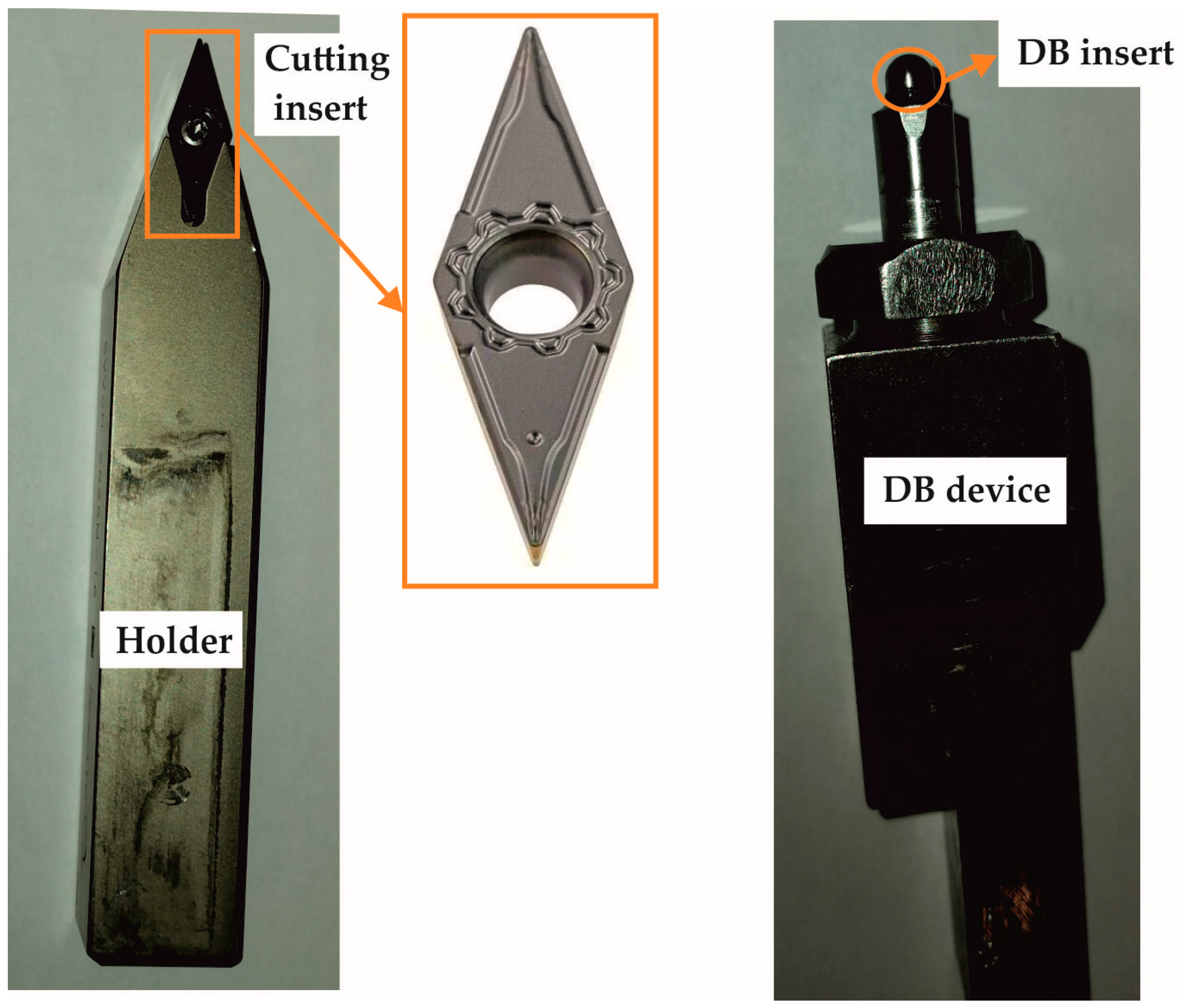
The turning and DB processes were performed on an Index Traub CNC lathe (Esslingen am Neckar, Germany) using flood lubrication and Vasco 6000 lubricant. The equipment for performing both processes is shown in Figure 2.
The cutting inserts used for the previous turning were of the VCMT 160404–F3P carbide type (main back angle α 0 = 7 ° ; radius at tool tip 0.4 mm). An SVVCN 2525M–16 holder was used, with main and auxiliary mounting angles of, respectively, χ c = 72.5 ° and χ c = 72.5 ° . The cutting inserts and the holder were supplied by ISCAR Bulgaria. The turning as pre-machining and DB were carried out in one clamping process. The burnishing device provided an elastic normal contact between the deforming diamond insert and the treated surface. The DB was implemented using spherical-ended polycrystalline diamond inserts.

2.3. Measurement of SI Characteristics

The two-dimensional roughness parameters were measured using a Mitutoyo Surftest SJ-210 surface roughness tester (Kawasaki, Japan) and the average arithmetic values from the measurements on six equally spaced sample generatrixes were obtained. A ZHVμ Zwick/Roell microhardness tester (Ulm, Germany) was used to establish the surface microhardness (0.05 kgf loading and 10 s time holding). The final surface microhardness value was considered to be the median of the clustering of 12 measurements of a specimen.
A Bruker D8 Advance diffractometer (Billerica, MA, USA) and Bruker DIFFRAC.Dquant V1.5 and Bruker.Eva V.5.2 software were used for the X-ray diffraction (XRD) analysis. The microstructure was observed via scanning electron microscopy (Zeiss Evo 10, Jena, Germany).

3. Experimental Results

3.1. Material Identification

The major chemical composition of the C45 steel is shown in Table 1. The remaining chemical elements (complementing up to 100 wt%) are Ti, V, W, Co, Pb, Zn, Zr, Bi and Ca. Table 2 lists the main mechanical characteristics for different material states. Normalisation improves the C45 steel machinability by cutting, refines the structure, reduces the static strength, retains the hardness and increases the ductility and impact toughness relative to the as-received state. The quenching and high-temperature tempering of the normalised structure significantly increased the hardness and the static and dynamic strength, but reduced the ductility.
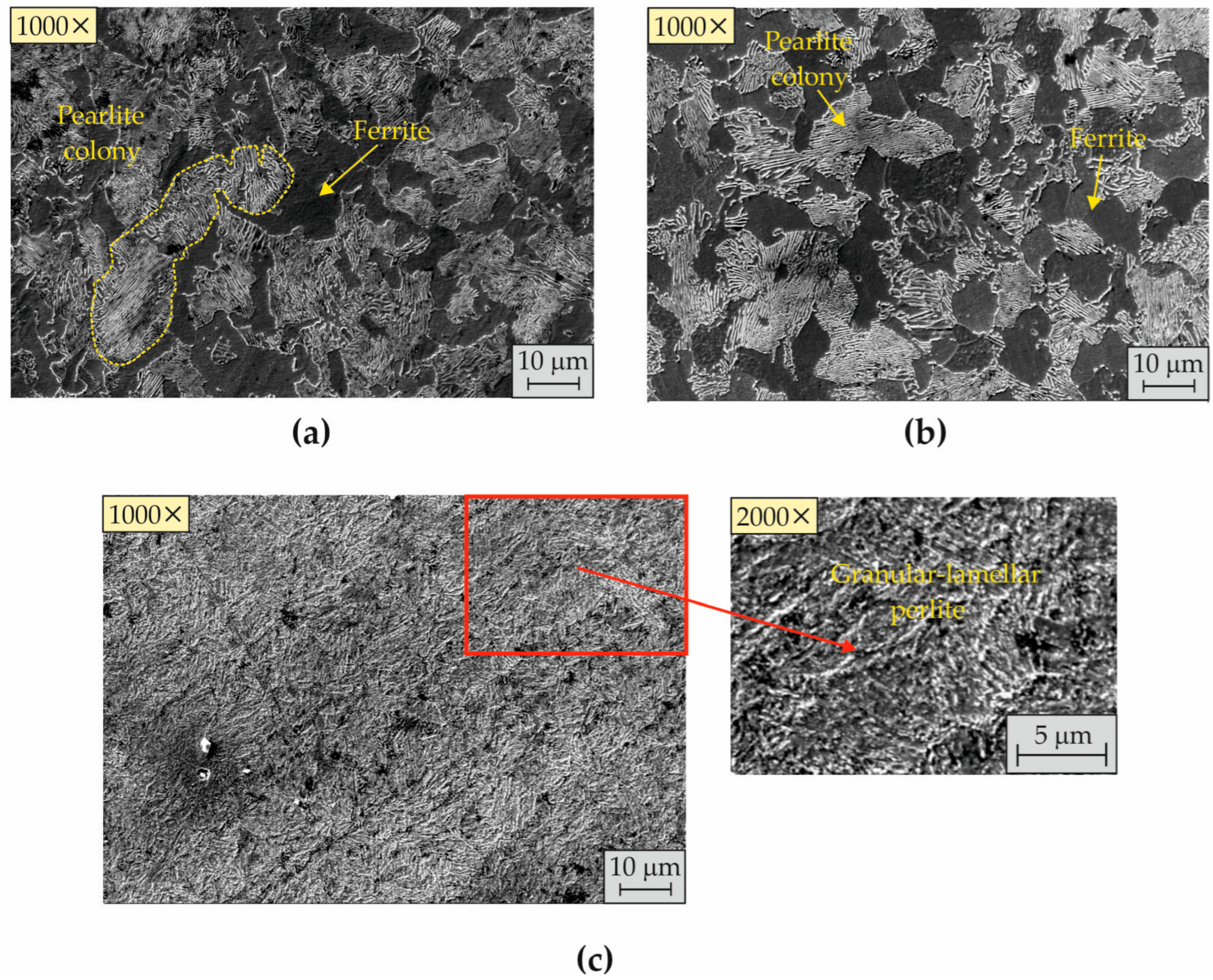
Figure 3 illustrates the evolution of the structure of the C45 steel resulting from heat treatments. The steel structure in the as-received condition was coarse-grained and inhomogeneous in terms of its ferrite–pearlite distribution (Figure 3a). After normalisation, a relatively finer homogeneous ferrite–pearlite structure was observable (Figure 3b). The structure resulting from the normalisation, quenching and high-temperature tempering was fine-grained, lamellar, homogeneous pearlite (Figure 3c).
The results of the XRD analysis are shown in Figure 4. The broadening of the ferrite lines of the N + Q + T specimen was caused by the remaining amount of cubic martensite, which explains the relatively high hardness and static strength (see Table 2). All further studies were performed on heat-treated (N + Q + T) cylindrical C45 steel specimens with a nominal diameter of 26 mm.

3.2. Investigation of the Previous Turning

3.2.1. Governing Factors, Levels and Objective Functions

The governing factors selected from the previous turning process were feed rate (f), cutting velocity ( v c ) and cutting depth ( a c ) (Table 3). The variation intervals were selected in accordance with the manufacturer’s recommendations regarding the limit values of these three turning parameters (https://www.hoffmann-group.com/GR/el/pangakis/p/261392-IC807, accessed on 14 September 2025). The objective function (Y) was the Ra. An experiment was carried out using a second-order optimal composition design. A new cutting insert was used, which had only been in operation for a few minutes before the experiment began.

3.2.2. Analysis of Variance Outcomes

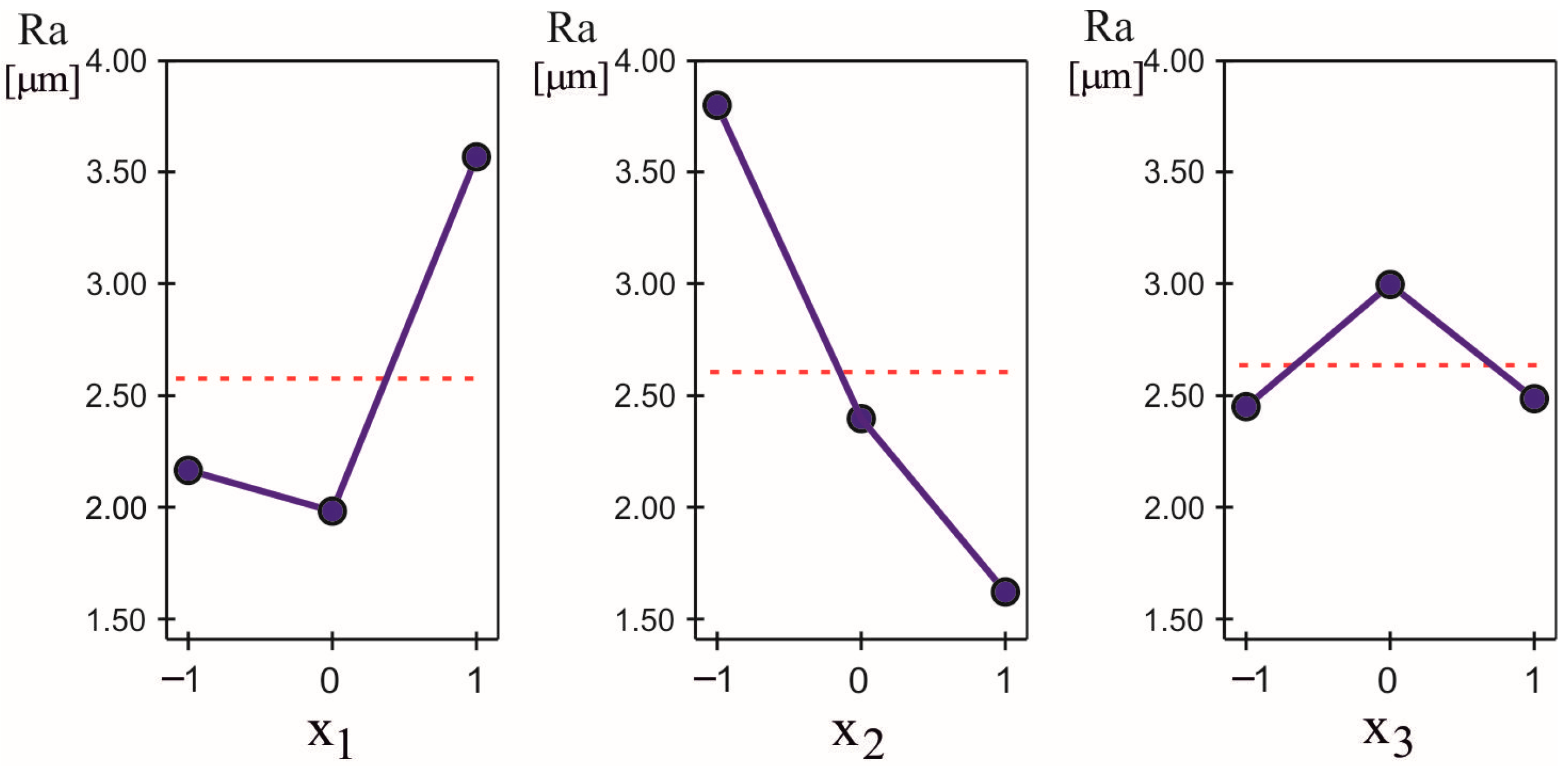
The obtained experimental results are shown in Table 4. An analysis of variance (ANOVA) was performed using QStatLab software version 6.1.1.3 [41] and Figure 5 shows the main effect—that is, the significance (degree of influence)—of each governing factor on the objective function. The most significant factor is cutting speed, and the least significant is cutting depth.

3.2.3. Dependence of the Ra on the Wear of the Cutting Insert

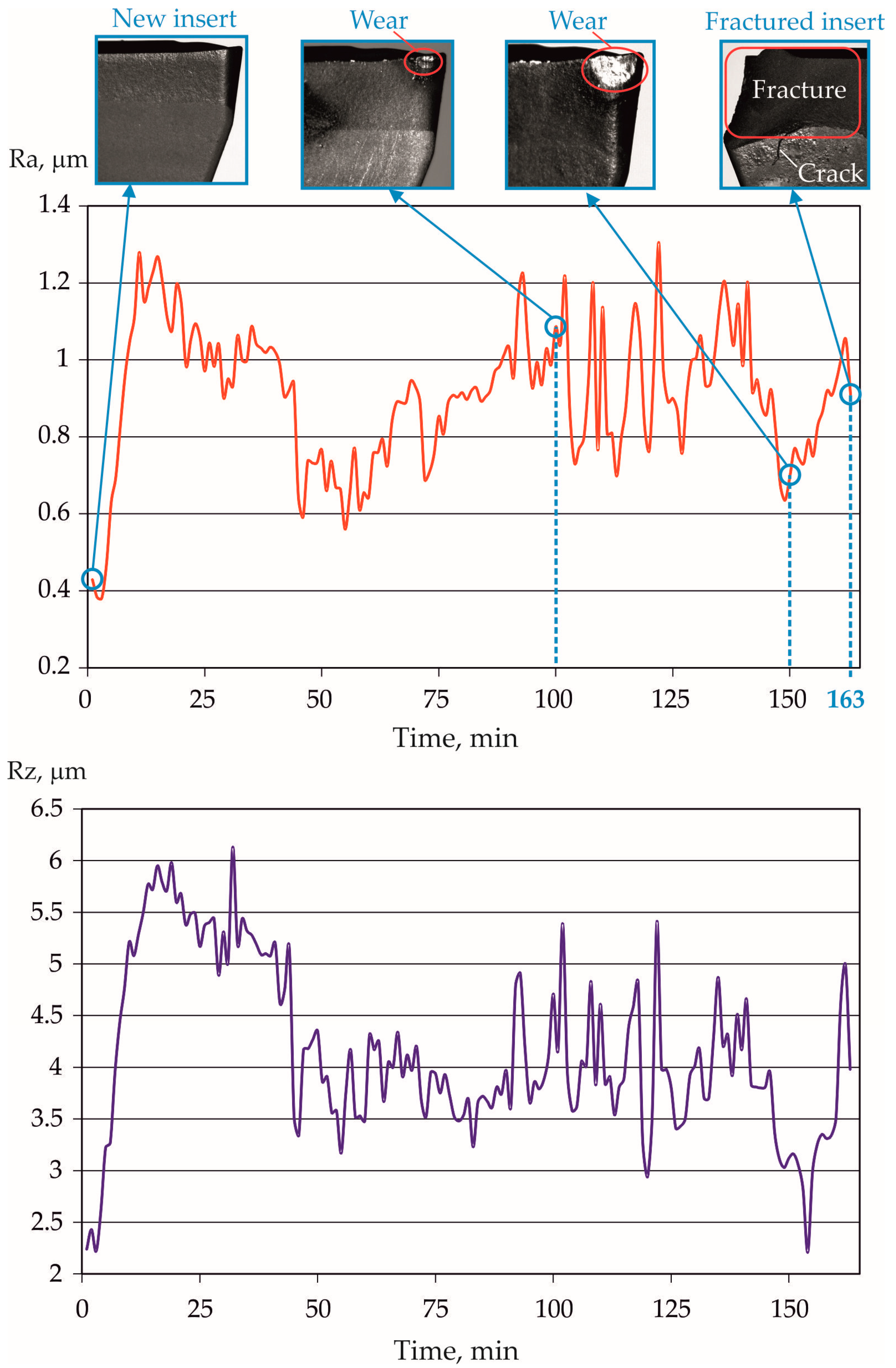
To reduce the auxiliary time of the experiment, we used C45 steel workpieces with a chemical composition similar to that shown in Table 1. The heat treatment parameters are given in Section 2.1. The workpieces had initial diameters of 85 mm and lengths of 200 mm. One end was fixed in a hydraulic chuck, the other supported by a rotating centre. The values of the governing factors of the turning process were selected from Table 4—the third experimental point, providing a minimum Ra of 0.614 μm—and comprised a feed rate of 0.050 mm/rev and a cutting velocity of 180 m/min (see Table 3). The cutting depth was 0.5 mm, so that the wear on the rear surface of the cutting wedge of the insert could be recorded. As can be seen from Figure 5, the cutting depth had little effect on the Ra. The size of the spot on the rear surface was accepted as a criterion representing wear. Roughness measurements (Ra and Rz parameters) were taken every minute. After 100 min of operation, the wear was 0.07 mm. At the 163rd minute, the insert broke. The dependence of Ra and Rz on insert wear is illustrated in Figure 6. The Ra varied from 0.381 to 1.305 μm, and the Rz from 2.21 to 6.13 μm.

3.3. DB Process Optimisation

3.3.1. Selection of Rainit Value

According to Korzynski [1], the Rainit (before DB) for alloys with lower hardness should range between 0.63 and 2.5 μm, while for alloys with higher hardness, this range should be 0.32 to 1.25 μm. For the heat-treated C45 steel, the middle of the second interval was chosen (i.e., R a i n i t = 0.785 μ m ). The values of the governing factors of the turning process were selected from Table 4, which provided approximately this Rainit—experimental point 3, R a i n i t = 0.614 μ m , at a feed rate of 0.05 mm/rev, a cutting velocity of 180 m/min and a cutting depth of 0.1 mm. As can be seen from Figure 5, the influence of cutting depth on the obtained average roughness was weak. A new cutting insert was used for the pre-turning to eliminate the effect of wear on the results obtained.

3.3.2. Factors and Levels of the DB Process

The selected governing factors of the DB process were the diamond insert radius (r), the burnishing force ( F b ) and the feed rate (Table 5). The burnishing velocity was 60 m/min and one tool pass was used. The variation intervals were selected based on previous experience with the DB of medium-carbon and low-alloy steels [11,12,18,42,43,44]. The objective functions were the Ra ( Y R a ) and surface microhardness ( Y H V ). A planned experiment using second-order optimal composition design (Table 6) was performed. The Ra and surface microhardness results are listed in Table 6.

3.3.3. Study of Objective Functions Y R a and Y H V

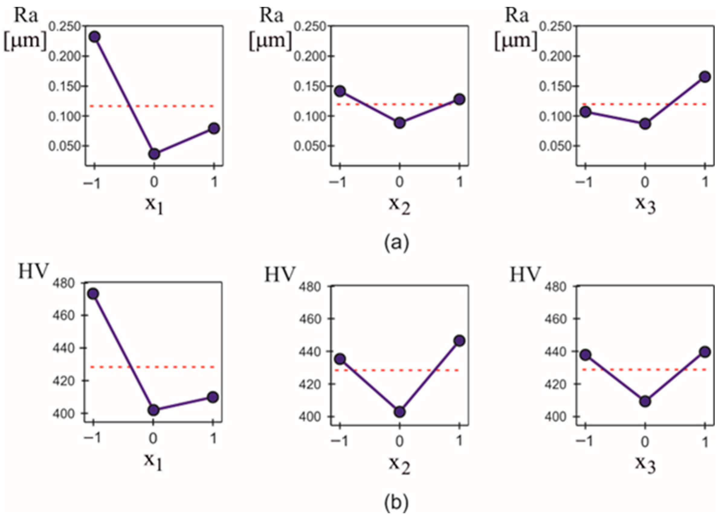
The experimental results from Table 6 were processed using an ANOVA and a regression analysis using QStatLab software. Figure 7 shows the main effects (influence of each factor on the objective functions) established by the ANOVA. The diamond insert radius had the strongest influence on the Ra, and the influence of the burnishing force was the weakest. The radius also had the strongest influence on the microhardness, with the feed having the weakest influence.
It has already been established [45] that to obtain correct results from regression analysis, the degree of the approximating polynomial must be one less than the number of levels of each of the governing factors. Regression models are second-order polynomials because the governing factors vary at three levels (see Table 5):
Y ( k ) X = b 0 ( k ) + i = 1 3 b i ( k ) x i + i = 1 2 j = i 1 3 b i j ( k ) x i x j + i = 1 3 b i i ( k ) x i 2 , k = 1 , 2
where X is the vector of the governing factors x i , and k = 1 , 2 shows the corresponding objective function of Y R a and Y H V , respectively.
The polynomial coefficients of the two objective functions are shown in Table 7. The probability of a coefficient being insignificant was p = 0.05. The correlation coefficients ( R 2 ) for the two objective functions ( Y R a and Y H V ) were 0.99092 and 0.99195, respectively, which shows good agreement between the models and the experimental results.
The absolute values of the coefficients b i ( k ) and b i i ( k ) are measures of the importance of the relevant governing factors. The numerical values in Table 7 confirm the results obtained by the ANOVA. The absolute values of the coefficients b i j ( k ) , i j , are measures of the interaction between the governing factors. The relatively smaller absolute values of the mixed coefficients, b i j ( k ) (see Table 7), compared to the absolute values of the corresponding coefficients, b i ( k ) and b i i ( k ) , are an indication of weak interactions between the factors. Figure 8 and Figure 9 show graphical visualisations of the models that confirm the conclusions drawn about the significance of the factors.

3.3.4. DB Optimisation

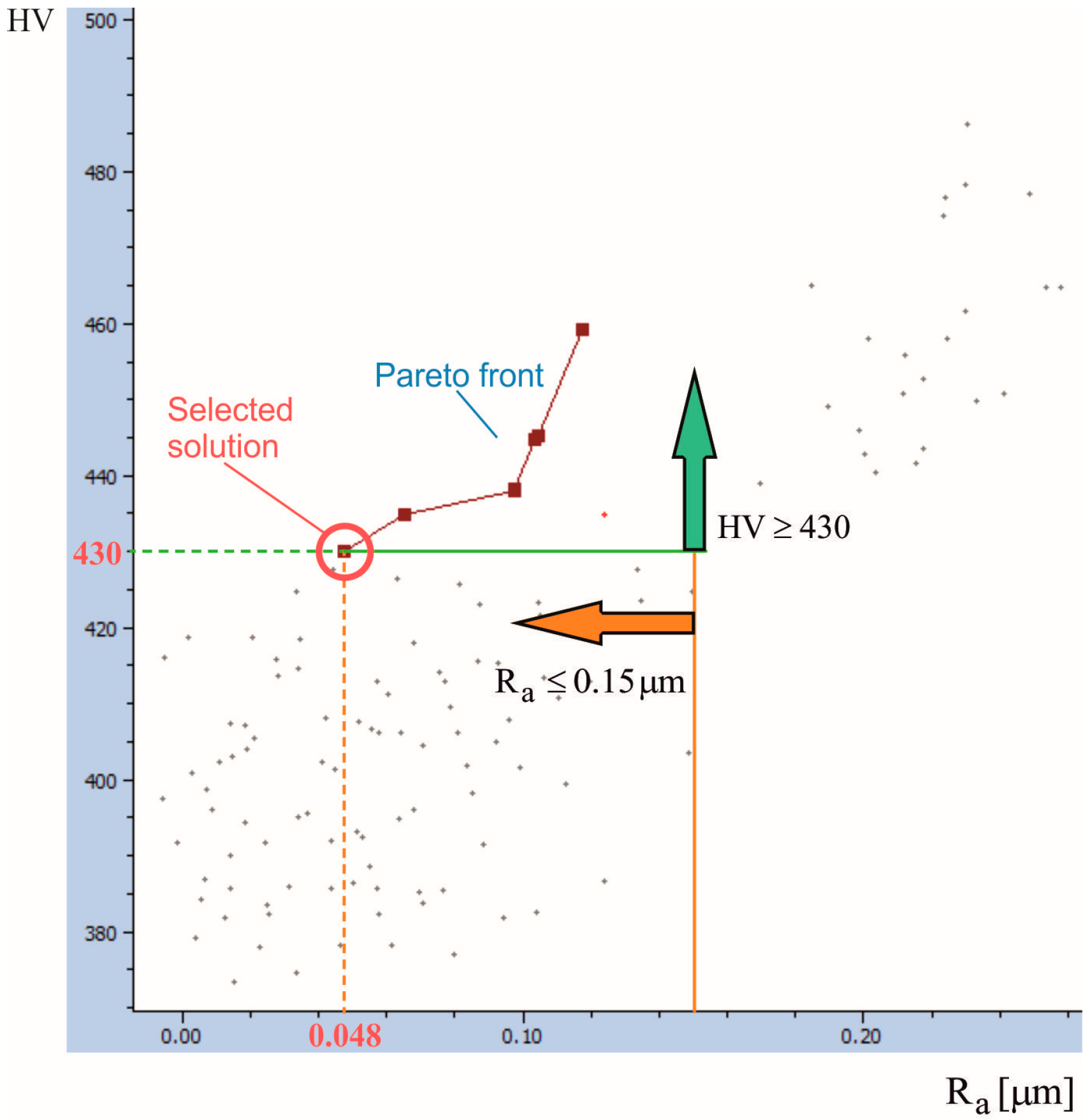
According to Korzynski [3], DB can be implemented as a smoothing, hardening or mixed process. Smoothing DB pursues a mirror-like surface (i.e., minimal roughness height parameters) while the hardening effect is less pronounced. Conversely, the hardening DB aims for maximum strain hardening, leading to maximum surface microhardness and maximum depth of the compressive residual stress zone. In the present study, a mixed process was chosen, based on a compromise optimal solution—that is, the goal was to simultaneously obtain a low (but not minimum) average roughness and a high (but not maximum) surface microhardness. The following dual-objective optimisation task was defined. The vector of the objective functions Y X = Y R a   Y H V T is set. The compromise optimal sizes of the governing factors x i * , i = 1 , 2 , 3 must be found, for which Y R a X * min and Y H V X * max , where x 1 * (diamond insert radius) can only accept integer values. The functional restrictions Y R a < 0.15 μ m and Y H V > 430 were imposed. A Pareto optimal solution approach was chosen. QStatLab and the SCAN method [41] were used because this method is suitable where any of the variables can only take integer values. The Pareto front is shown in Figure 10. The selected compromise optimal solution provided an integer value for the diamond radius of x 1 * = 0 , x 2 * = x 3 * = 1 —that is, r * = 3   m m , F b * = 200    N and f * = 0.08    m m / r e v . The DB was implemented in further studies using these governing factor values. The compromise optimal values of the objective functions were Y R a * = 0.048    μ m and H V * = 430 .

3.4. Influence of the Rainit on the SI Characteristics After DB

3.4.1. Providing a Different Rainit

To reduce the duration of the experiment, different Rainits were obtained using different combinations of feed rate and cutting velocity (based on Figure 5)—that is, the different Rainits were obtained artificially, and were not a consequence of the natural wear of the cutting insert. A new (unused) cutting insert was used to eliminate the effects of its wear on the roughness parameters and surface microhardness.

3.4.2. Influence of Rainit on Surface Roughness and Microhardness

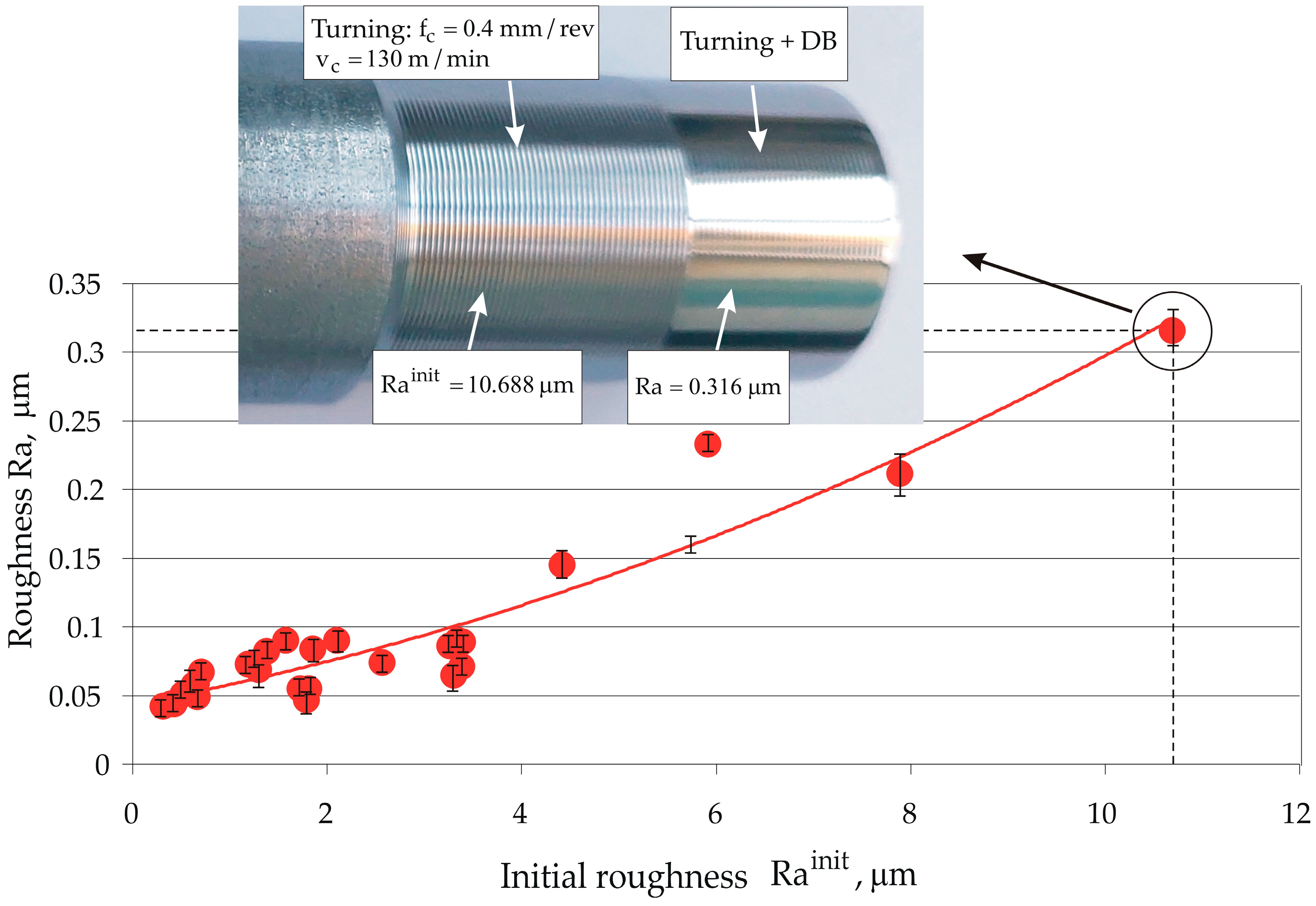
The trendline of the dependence of the Ra on the R a i n i t shows a continuous increase in Ra, from 0.042 to 0.316 μm, according to a nonlinear law (Figure 11). The Ra maintained stable values, from 0.042 to 0.089 μm, when the R a i n i t increased to 3.379 μm, then it smoothly increased to 0.316 μm when R a i n i t = 10.688 μ m . This latter illustrated the ability of DB to drastically reduce the height parameters of the initial roughness—that is, the reduction being by approximately 34 times. To obtain mirror-like surfaces, R a i n i t < 3.379 μ m .
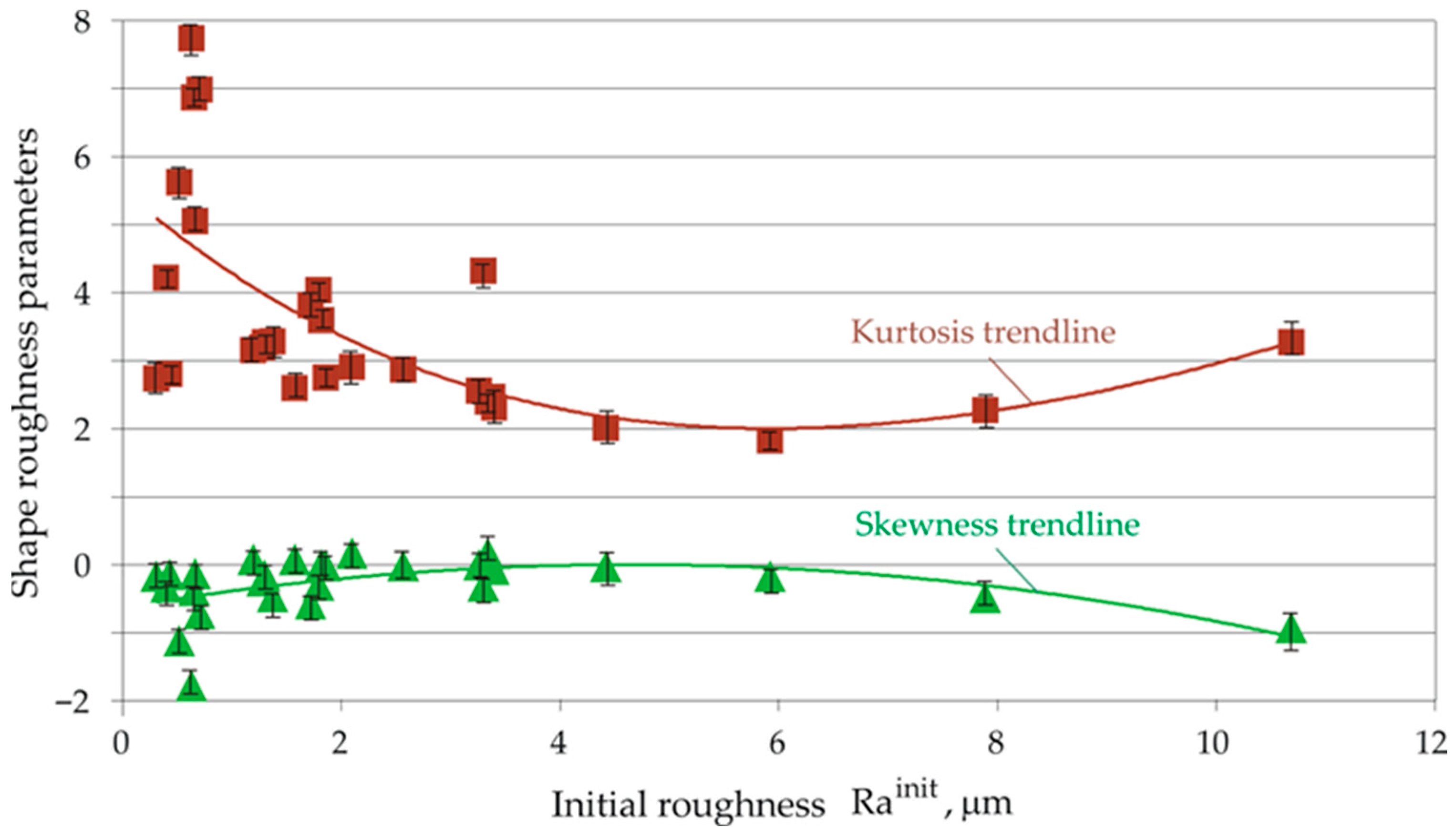
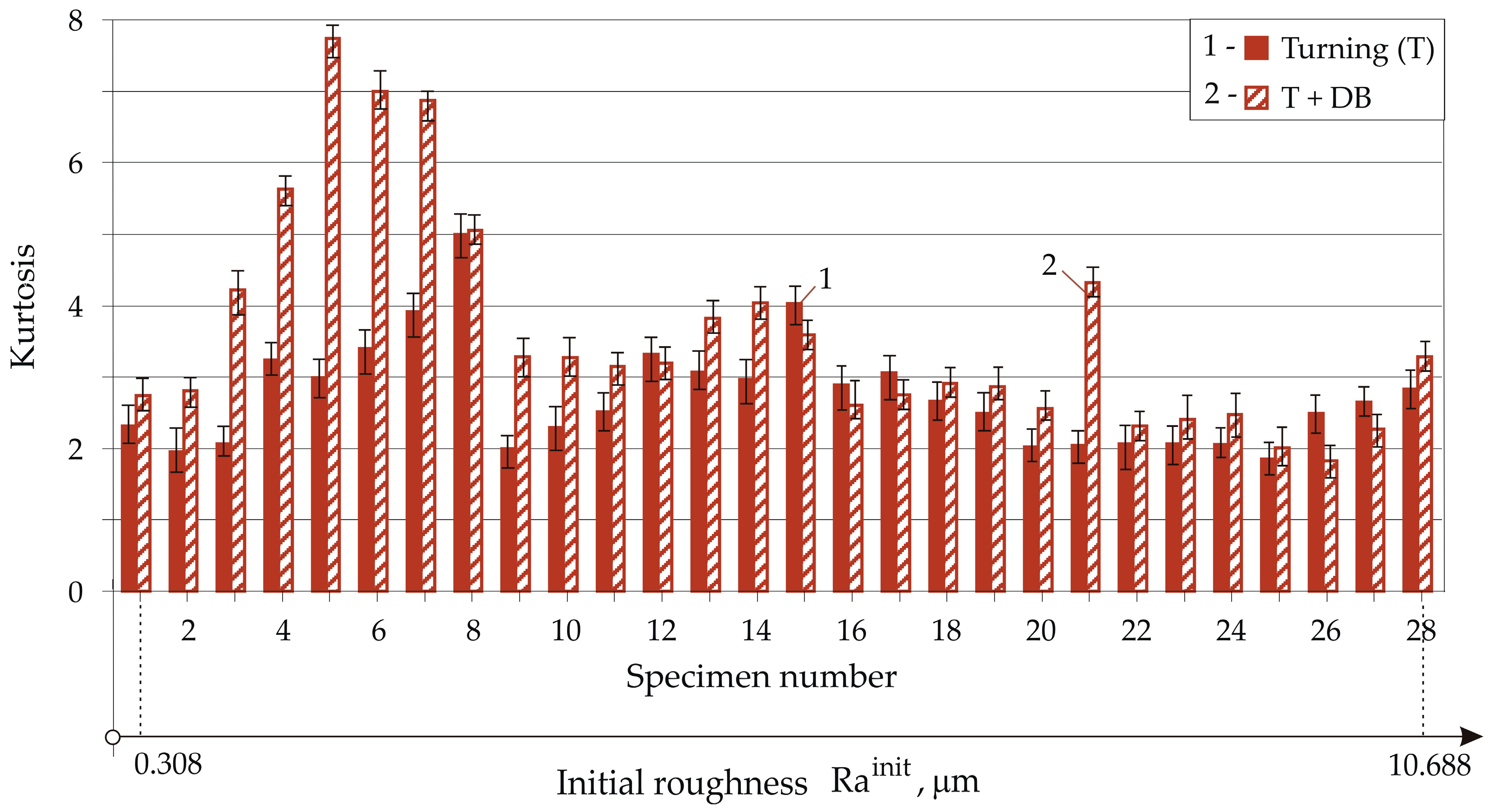
Over the entire range of variation in the Rainit, DB provided stable negative values of the skeweness (Figure 12). More negative skewness occurred at the beginning and end of the R a i n i t variation interval. The trendline of change in kurtosis (which can only take positive values) was the opposite to the skewness trend, with higher kurtosis values corresponding to more negative skewness. When the skewness was close to zero, the kurtosis took on minimal values. It is known [46] that the skewness and kurtosis are of significant importance in the tribological behaviour of the machined surface. A combination of more-negative skewness and kurtosis greater than three increases the wear resistance of the surface under boundary lubrication friction conditions [47,48]. Therefore, when the goal is to increase the wear resistance of a diamond-burnished surface under boundary friction conditions, the R a i n i t should be less than 0.7 μm.
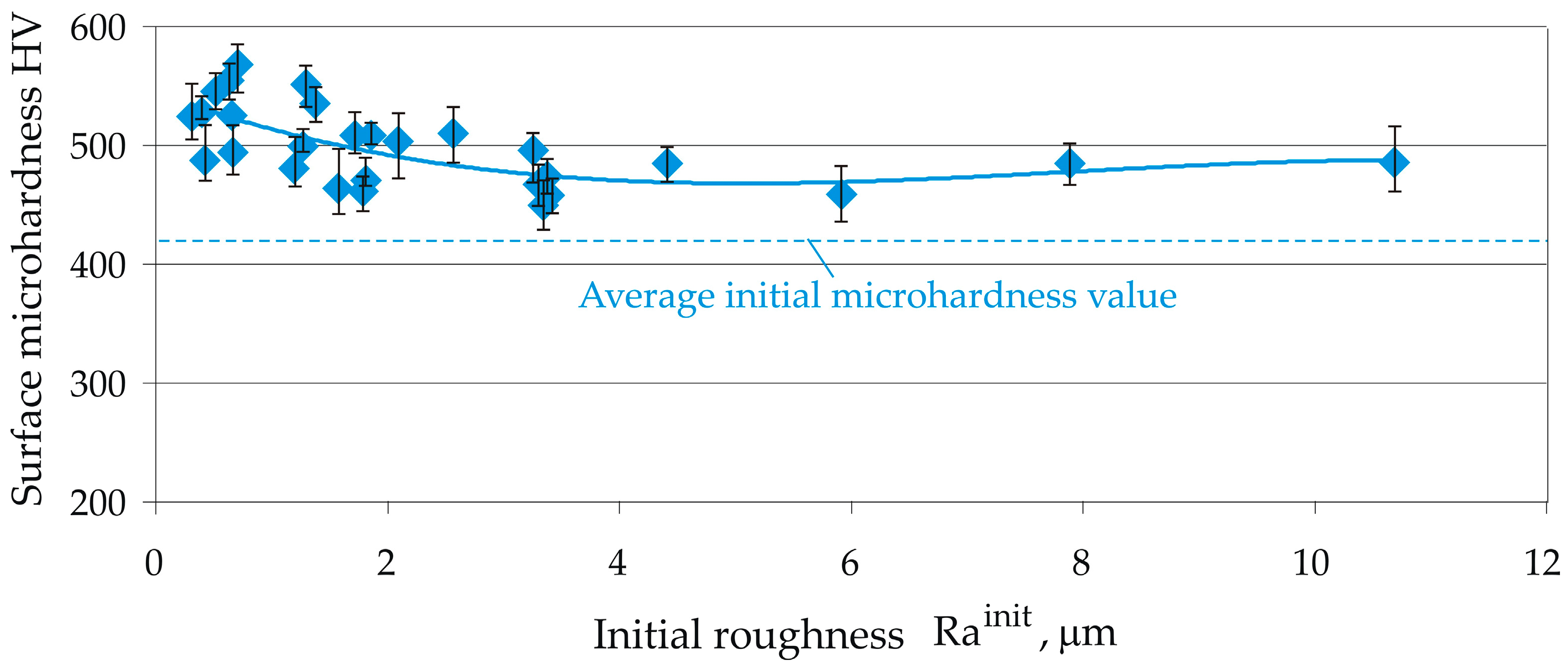
Figure 13 and Figure 14 illustrate the evolution of the skewness and kurtosis after successive turning and DB depending on the Rainit. With three exceptions, which were very close to zero, the turning provided positive skewness. By contrast, DB transformed the skewness from positive to negative. This, together with the significant reduction in the roughness height parameters (see Figure 11), favoured the tribological behaviour of the DB surface. When the Rainit was below 5 μm, there was a consistent tendency for DB to increase the kurtosis values obtained after turning. Exceptions to this trend were observed at higher values of Rainit.
As the Rainit increased to approximately 3.4 μm, the microhardness decreased smoothly, then remained relatively constant (Figure 15). To achieve maximum surface microhardness, the Rainit should be less than 0.8 μm.

3.5. Verification of the SI Stability Under Production Conditions

The effects of the Rainit on the SI characteristics after DB are reported in detail in Section 3.4. Different Rainit values were created artificially by varying combinations of the feed rate and cutting velocity in the previous turning. Under production conditions, the previous turning was performed using constant (optimal) values for the governing factors.
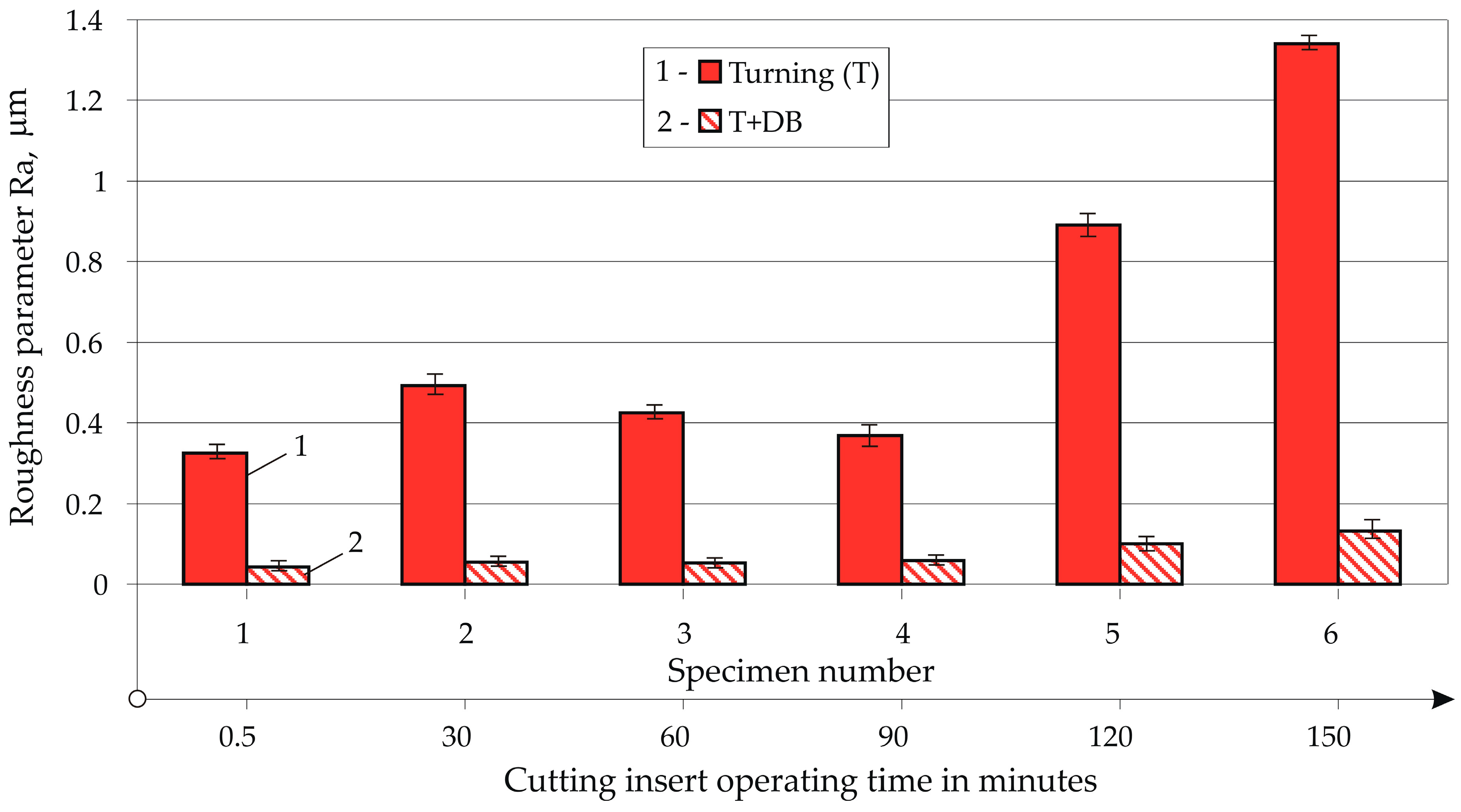
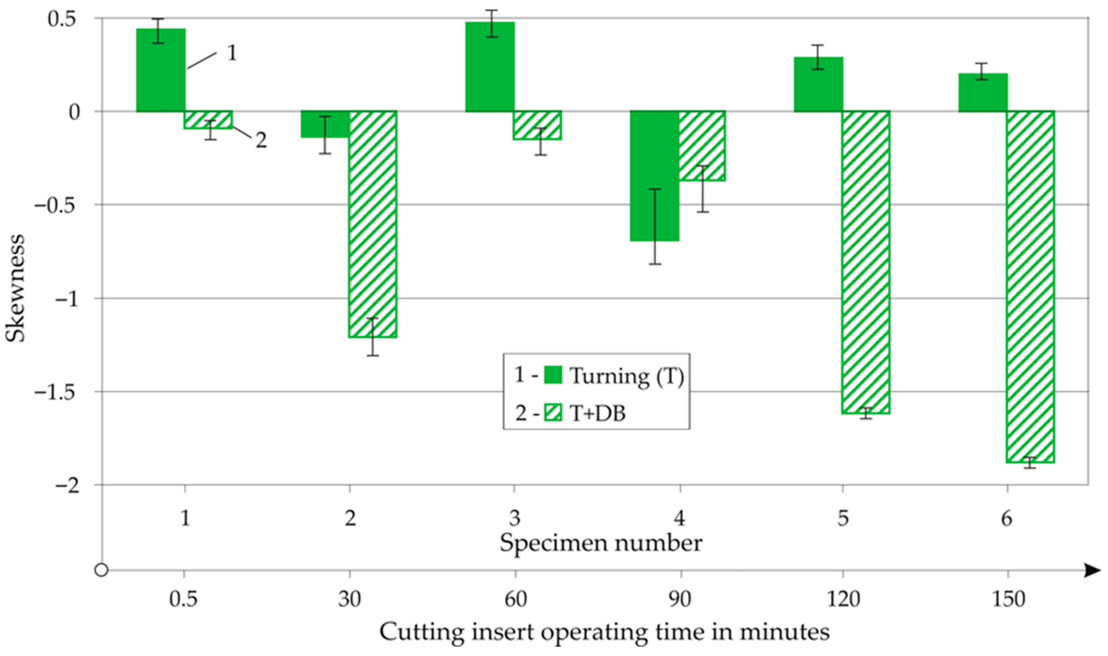
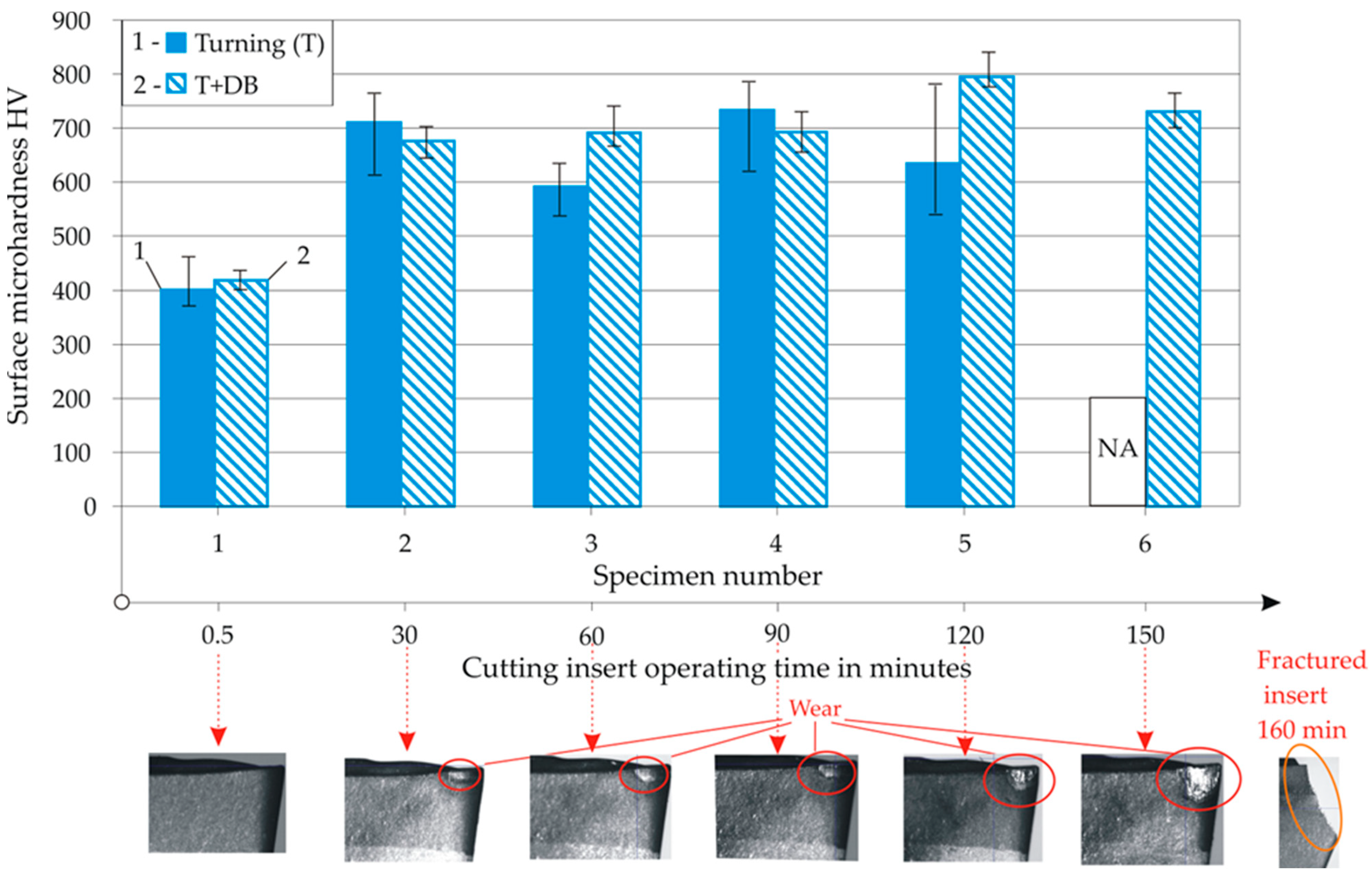
The turning was implemented using a feed rate of 0.05 mm/rev and a cutting velocity of 180 m/min because this combination provides a minimum Ra roughness parameter (see Table 4). The experiment was started with a new (unused) cutting insert. The Ra and microhardness were measured after turning and DB were performed on the first part, and then, after every 30 min of cutting insert operation, the Ra and surface microhardness were measured on the corresponding parts until the insert was completely worn (at the 160th minute). The results for the roughness parameters and surface microhardness are shown in Figure 15, Figure 16, Figure 17 and Figure 18.
During the first 90 min of cutting insert operation, the turning provided stable values of Rainit in the range of 0.325–0.493 μm (Figure 16). Over the same time range, the subsequent DB achieved a mirror-like surface with Ra = 0.044–0.059 μm. From the 90th to 150th minutes, the Rainit showed a steady trend of linear increase (R2 = 0.998), from 0.368 to 1.341 μm. Over this time range, the Ra after DB also increased linearly (R2 = 1), from 0.059 to 0.133 μm. It can be concluded that DB can provide a stable Ra of 0.059 μ m of the resulting mirror-like surface during the first 90 min of operation of a new (unused) cutting insert.
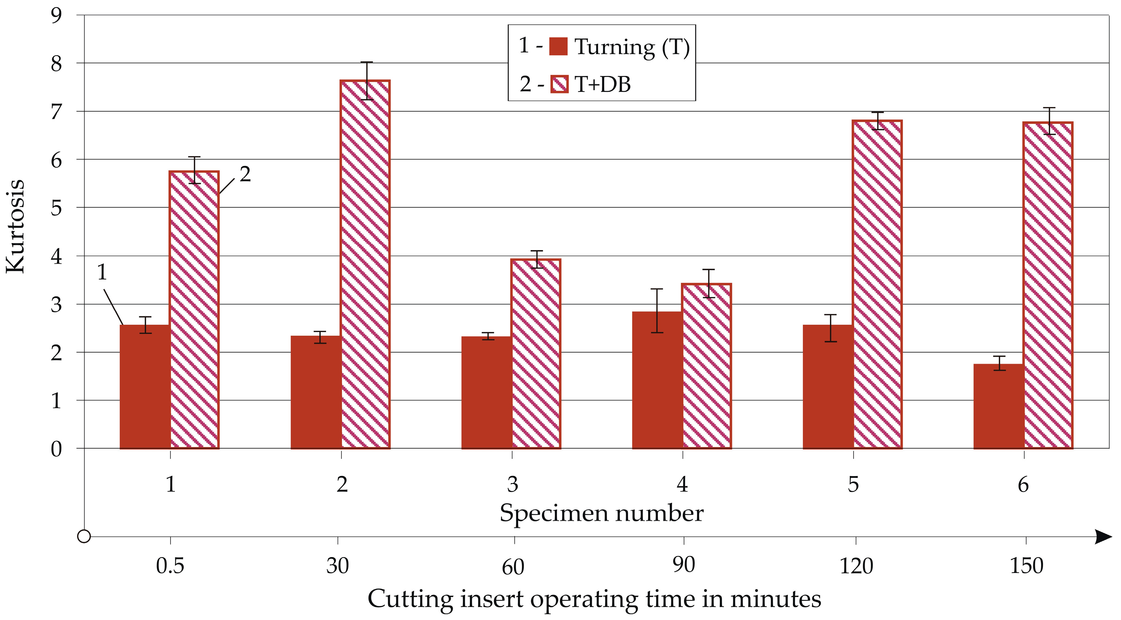
For the investigated service life (150 min) of the cutting insert, turning provided positive skewness (or negative with small absolute values) (Figure 17) and the kurtosis was less than three (Figure 18). The DB provided negative skewness and a kurtosis greater than three. This, combined with the low Ra, was a prerequisite for increased wear resistance of the diamond-burnished surface under boundary lubrication conditions [47,48].
Whereas the wear on the cutting insert did not significantly affect the roughness parameters obtained after DB (which are a geometric characteristic of SI), the effect of this wear on the surface microhardness was significant (Figure 19). In the first minute, when there was no wear on the rear surface of the cutting wedge of the insert, the microhardness after turning was 401 HV. The DB increased the microhardness to 418 HV. After the formation of a wear spot, recorded after 30 min of operation of the cutting insert, the microhardness after turning significantly increased to between 592 and 733 HV (due to the high Ra of 1.341 μm, the surface microhardness of the sixth sample (150 min) could not be measured correctly and, therefore, is not shown in Figure 18). After the subsequent DB, the microhardness varied from 676 to 795 HV. It should be noted that, for each specimen, the final surface microhardness value was considered to be the median of the clustering of 12 measurements of a specimen. Considering the scattering shown in Figure 19, DB provided significantly more-consistent microhardness values than the previous turning. However, the main reason for the high microhardness after DB was the high initial microhardness obtained after turning, when a wear spot was formed on the back surface of the cutting insert. The presence of wear caused an increase in the frictional work between the cutting insert and the machined surface for two reasons: (1) it changed the geometry of the cutting wedge; and (2) it increased the coefficient of friction due to the destruction of the coating on the insert. The increased frictional work dissipated into heat, which, given the changed colour of the chips (dark blue), was significant. This heat was concentrated in a small contact area for a very short time, which is why the temperature at the centre of the contact spot was characterised by high increasing and decreasing gradients given the significant peripheral speed (180 m/min) of the turned surface and the use of flood lubrication. There was also an effect of processing using concentrated energy flows (i.e., electron beam, laser beam, friction stir and others). In addition, the friction was accompanied by SPD. As a result, a complex mechanism of thermo-mechanical strengthening of the surface layer occurred, in which both strain hardening and transformation hardening took place.
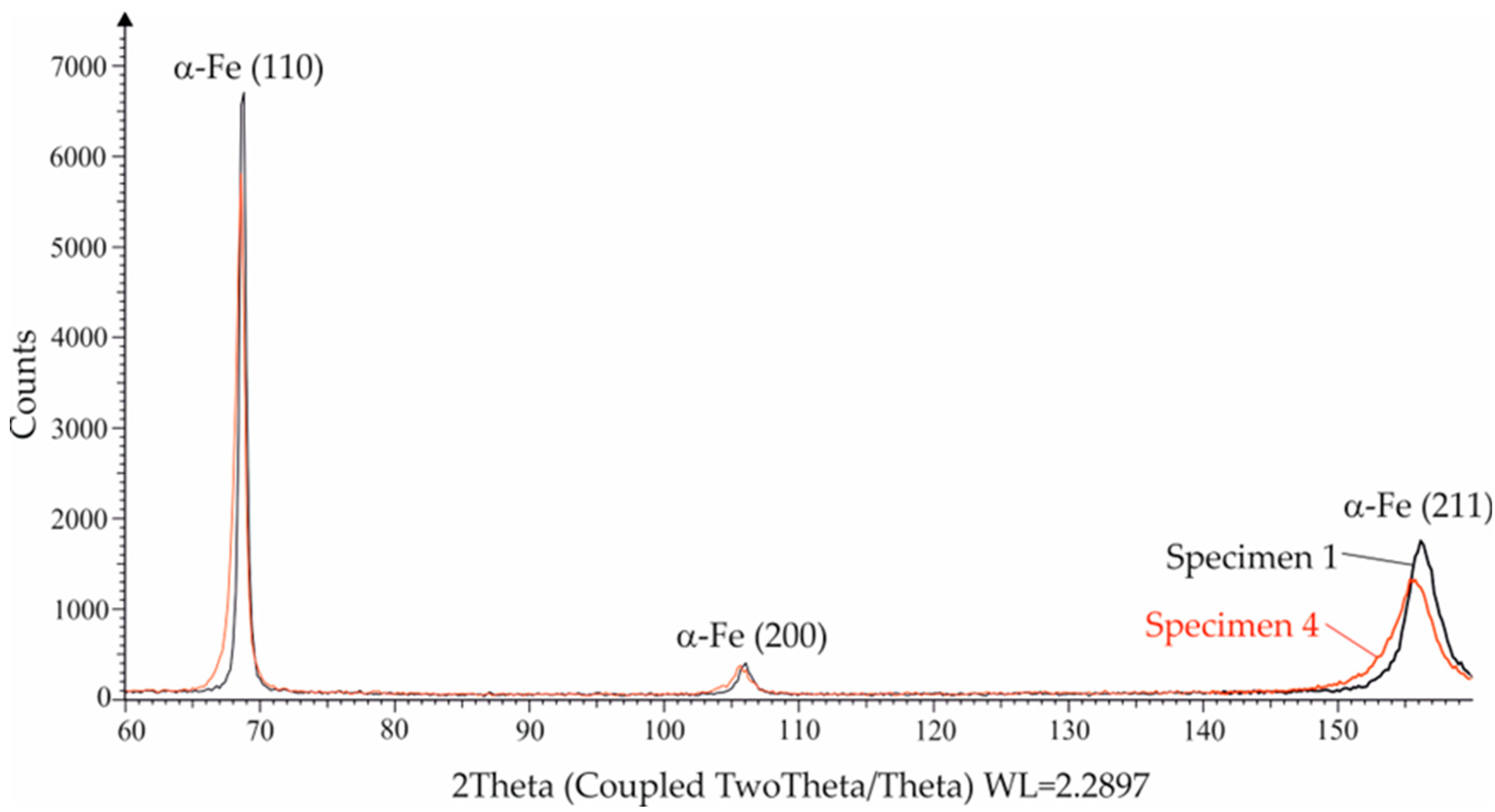
The presence of defects introduced into the crystal structure of the surface layer due to wear of the cutting insert during the previous turning was confirmed by the XRD analysis (Figure 20). The broadening of the ferrite lines of Specimen 4 compared to Specimen 1 (see Figure 19 for the specimen numbers) is an indication of such a change in the crystal structure, the cause of which could be surface texturing, strain hardening, transformation hardening, introduced residual stresses or other effects. In the presence of a sufficiently powerful heat flux (resulting from friction and plastic deformation), concentrated in a small contact area, martensitic transformation is possible, which would lead to a significant increase in the surface microhardness after previous turning. This process of thermo-mechanical strengthening, resulting from the wear of the cutting insert, is the topic of further in-depth study by the authors and subsequent publications will follow.

4. Conclusions

Using a holistic approach, the effects of DB on the roughness parameters and surface microhardness of heat-treated C45 steel under conditions of constantly changing Rainit due to wear of the cutting insert in the previous turning were established. Our most important findings are as follows:
  • The service life of the cutting insert to complete wear, when operating using optimal parameters in the turning process, is 163 min, during which time the Ra changed unevenly from 0.38 to 1.31 μm and the Rz from 2.21 to 6.13 μm.
  • Under conditions of artificially created Rainit values of 0.308 to 10.688 μm, DB provided stable Ra values from 0.042 to 0.089 μm when the Rainit increased to 3.379 μm. The skewness and kurtosis were weakly affected by Rainit. Whereas turning led to positive skewness and a kurtosis below three, DB provided sustained negative skewness and kurtosis values above three. This combination of skewness and kurtosis values, together with the low Ra (mirror-like surface), favoured the tribological behaviour of the diamond-burnished surface under boundary friction conditions. The surface microhardness varied from 461 to 568 HV.
  • Under production conditions, with the previous turning performed using optimal parameters, DB provided a stable Ra of ≤0.059 µm of the resulting mirror-like surface during the first 90 min of operation of a new (unused) cutting insert, after which the Ra values increased linearly, from 0.059 to 0.133 μm. After 30 min of operation up to the cutting insert being completely worn, the microhardness after DB varied in a range of 676 to 795 HV. The high surface microhardness was due to a complex process of surface thermo-mechanical strengthening (including strain and transformation hardening) in the previous turning caused by wear on the cutting insert.
  • The in-depth study of the process of thermo-mechanical strengthening due to cutting insert wear requires numerous additional studies, which will be conducted by the authors, and the results will be the subject of a subsequent publication.

Author Contributions

Conceptualization, J.M. and G.D.; methodology, J.M. and G.D.; software, J.M., G.D. and M.I.; validation, J.M., G.D., and K.A.; formal analysis, J.M. and G.D.; investigation, K.A., P.D., M.I., G.D., and J.M.; resources, J.M., G.D. and K.A.; data curation, J.M. and G.D.; writing—original draft preparation, J.M. and G.D.; writing—review and editing, J.M. and G.D.; visualization, J.M., G.D., M.I., and P.D.; supervision, J.M.; project administration, J.M. and G.D.; funding acquisition, J.M. and G.D. All authors have read and agreed to the published version of the manuscript.

Funding

This research was funded by the European Regional Development Fund under the Operational Program”Scientific Research, Innovation and Digitization for Smart Transformation 2021–2027”, Project CoC “SmartMechatronics, Eco- and Energy Saving Systems and Technologies”, BG16RFPR002-1.014-0005.

Institutional Review Board Statement

Not applicable.

Informed Consent Statement

Not applicable.

Data Availability Statement

The original contributions presented in the study are included in the article; further inquiries can be directed to the corresponding authors.

Conflicts of Interest

The authors declare no conflicts of interest.

Abbreviations

ANOVAAnalysis of variance
DBDiamond burnishing
SISurface integrity
SPDSurface plastic deformation
XRDX-ray diffraction

References

  1. Korzynski, M. (Ed.) Slide diamond burnishing. In Nonconventional Finishing Technologies; Polish Scientific Publisher: Warsaw, Poland, 2013; pp. 9–34. [Google Scholar]
  2. Hull, E.H.; Nerad, A.J. Irregular Diamond Burnishing Tool. United States Patent 2966722, 3 January 1961. [Google Scholar]
  3. Korzynski, M. Modeling and experimental validation of the force-surface roughness relation for smoothing burnishing with a spherical tool. Int. J. Mach. Tools Manuf. 2007, 47, 1956–1964. [Google Scholar] [CrossRef]
  4. Korzynski, M. A model of smoothing slide ball-burnishing and an analysis of the parameter interaction. J. Mater. Process. Technol 2009, 209, 625–633. [Google Scholar] [CrossRef]
  5. Felho, C.; Varga, G. CAD and FEM modelling of theoretical roughness in diamond burnishing. Int. J. Precis. Eng. Manuf. 2022, 23, 375–384. [Google Scholar] [CrossRef]
  6. Felho, C.; Varga, G. 2D FEM investigation of residual stress in diamond burnishing. J. Manuf. Mater. Process. 2022, 6, 123. [Google Scholar] [CrossRef]
  7. Chodor, J.; Kukielka, L.; Chomka, G.; Bohdal, L.; Patyk, R.; Kowalik, M.; Trzepiecinski, T.; Radchenko, A.M. Using the FEM method in the prediction of stress and deformation in the processing zone of an elastic/visco-plastic material during diamond sliding burnishing. Appl. Sci. 2023, 13, 1963. [Google Scholar] [CrossRef]
  8. Borysenko, D.; Welzel, F.; Karpuschewski, B.; Kundrák, J.; Voropai, V. Simulation of the burnishing process on real surface structures. Precis. Eng. 2021, 68, 166–173. [Google Scholar] [CrossRef]
  9. Bembenek, M.; Kopei, V.; Ropyak, L.; Levchuk, K. Stressed state of chrome parts during diamond burnishing. Met. Adv. Technol. 2023, 45, 239–250. [Google Scholar] [CrossRef]
  10. Jimenez-Garcia, J.I.; Gapilla, G.C.; Balvantin-Garciq, A.J.; Travieso-Rodriguez, J.A.; Ruiz-Lopez, I.; Saldana-Robles, A. A numerical investigation into the influence of the slide burnishing process on the real surface roughness and residual stress profiles of AHSS. J. Mater. Res. Techol 2024, 33, 1406–1419. [Google Scholar] [CrossRef]
  11. Saldana-Robles, A.; Plascencia-Mora, H.; Aguilera-Gomez, E.; Saldana-Robles, A.; Marquez-Herrera, A.; Diosdado-De la Pena, J.A. Influence of ball-burnishing on roughness, hardness and corrosion resistance of AISI 1045 steel. Surf. Coat. Technol. 2018, 339, 191–198. [Google Scholar] [CrossRef]
  12. Skoczylas, A.; Zaleski, K. Study on the surface layer properties and fatigue life of a workpiece machined by centrifugal shot peening and burnishing. Materials 2022, 15, 6677. [Google Scholar] [CrossRef]
  13. Bourebia, M.; Bouri, A.; Hamadache, H.; Achouri, S.; Laouar, L.; Gharbi, A.; Ghelloudj, O.; Bouhamla, K. Study of the effect burnishing on superficial hardness and hardening of S355JR steel using experimental planning. Energy Procedia 2019, 157, 568–577. [Google Scholar] [CrossRef]
  14. Koszela, W.; Balon, P.; Rejman, S.E.; Kielbasa, B.; Smusz, R.; Bembenek, M. The influence of structuring surfaces and slide burnishing on tribological properties. Met. Adv. Technol. 2023, 45, 403–421. [Google Scholar] [CrossRef]
  15. Hamadache, H.; Zemouri, Z.; Laouar, L.; Dominiak, S. Improvement of surface conditions of 36CrNiMo6 steel by ball burnishing process. J. Mech. Sci. Technol. 2014, 28, 1491–1498. [Google Scholar] [CrossRef]
  16. Kuznetsov, V.P.; Tarasov, S.Y.; Dmitriev, A.I. Nanostructuring burnishing and subsurface shear instability. J. Mater. Process Technol. 2015, 217, 327–335. [Google Scholar] [CrossRef]
  17. Zielecki, W.; Bucior, M.; Trzepiecinski, T.; Ochał, K. Effect of slide burnishing of shoulder fillets on the fatigue strength of X19NiCrMo4 steel shafts. Int. J. Adv. Manuf. Technol. 2020, 106, 2583–2593. [Google Scholar] [CrossRef]
  18. Kluz, R.; Antosz, K.; Trzepieciński, T.; Bucior, M. Modelling the Influence of Slide Burnishing Parameters on the Surface Roughness of Shafts Made of 42CrMo4 Heat-Treatable Steel. Materials 2021, 14, 1175. [Google Scholar] [CrossRef]
  19. Dunchev, V.P. Comprehensive model of the micro-hardness of diamond burnished 41Cr4 steel specimens. J. Tech. Univ. Gabrovo 2020, 60, 25–33. [Google Scholar]
  20. Taamllah, O.; Hamadache, H.; Mokas, N.; Amirat, A.; Hamadi, B. Investigation of the effect of slide diamond burnishing process on the mechanical performance of GCr15 steel. J. Fail. Anal. Prev. 2023, 23, 1101–1113. [Google Scholar] [CrossRef]
  21. Labanowski, J.; Ossowska, A. Influence of burnishing on stress corrosion cracking susceptibility of duplex steel. J. Achiev. Mater. Manuf. Eng. 2006, 19, 46–52. [Google Scholar]
  22. Kuznetsov, V.P.; Kosareva, A.V. Increase of wear and heat resistance of the AISI 304 steel surface layer by multi-pass nanostructuring burnishing. J. Mater. Eng. 2023, 1, 55–61. [Google Scholar] [CrossRef]
  23. Aliev, K.T.; Aslanov, T.I. The influence of diamond burnishing on the fatigue strength and wear resistance of the shafts of petroleum chains. Chem. Pet. Eng. 1979, 15, 459–461. [Google Scholar] [CrossRef]
  24. Argirov, Y.B.; Maximov, J.T.; Duncheva, G.V.; Anchev, A.P.; Dunchev, V.P.; Mechkarova, T.M. Evolution of surface integrity characteristics and mechanical behavior of diamond burnished and turned AISI 304 steel specimens after prolonged exposure to natural seawater. Coatings 2025, 15, 31. [Google Scholar] [CrossRef]
  25. Maximov, J.; Duncheva, G.; Anchev, A.; Dunchev, V.; Anastasov, K.; Argirov, Y. Sustainable Diamond Burnishing of Chromium–Nickel Austenitic Stainless Steels: Effects on Surface Integrity and Fatigue Limit. Appl Sci 2024, 14, 9031. [Google Scholar] [CrossRef]
  26. Maximov, J.T.; Duncheva, G.V.; Dunchev, V.P.; Anchev, A.P. Different strategies for finite element simulations of static mechanical surface treatment processes—A comparative analysis. J. Braz. Soc. Mech. Sci. Eng. 2021, 43, 371. [Google Scholar] [CrossRef]
  27. Kato, H.; Hirokawa, W.; Todaka, Y.; Yasunaga, K. Improvement in surface roughness and hardness for carbon steel by slide burnishing process. Mater. Sci. Appl. 2021, 12, 171–181. [Google Scholar] [CrossRef]
  28. Abdallah, A.; Abdelsalam, M.; Ibrahim, A.A.; Hassan, H.A.; Youssef, W.F. The effect of initial surface profile on the surface roughness and roundness in ball burnishing process. J. Eng. Sci. 2025, 53, 140–156. [Google Scholar] [CrossRef]
  29. Magnabosco, I.; Ferro, P.; Tiziani, A.; Bonollo, F. Induction heat treatment of a ISO C45 steel bar: Experimental and numerical analysis. Comput. Mater. Sci. 2006, 35, 98–106. [Google Scholar] [CrossRef]
  30. Blaoui, M.M.; Zemri, M.; Brahami, A. Effect of heat treatment parameters on mechanical properties of medium carbon steel. Mech. Mech. Eng. 2018, 22, 909–918. [Google Scholar] [CrossRef]
  31. Wozniak, W.; Sasiadek, M.; Jachowicz, T.; Edl, M.; Zajac, P. Studies on the mechanical properties of C45 steel with martensitic structure after a high tempering process. Adv. Sci. Technol. Res. J. 2022, 16, 306–315. [Google Scholar] [CrossRef]
  32. Bubphachot, B.; Premanond, V.; Keawtatip, P. Optimum heat treatment conditions for C45 steel in fine blanking process. Eng. Appl. Sci. Res. 2005, 32, 551–562. [Google Scholar]
  33. Laouissi, A.; Blaoui, M.M.; Abderazek, H.; Nouioua, M.; Bouchoucha, A. Heat treatment process study and ANN-GA based multi-response optimization of C45 steel mechanical properties: A. Laouissi et al. Met. Mater. Int. 2022, 28, 3087–3105. [Google Scholar] [CrossRef]
  34. Al-Qawabah, S.M.A.; Alshabatat, N.; Al-Qawabeha, U.F. Effect of annealing temperature on the microstructure, microhardness, mechanical behavior and impact toughness of low carbon steel grade 45. Int. J. Eng. Res. Appl. 2012, 2, 1550–1553. [Google Scholar]
  35. Omar, A.A.; El-Shennawy, M.; Elhabib, O.A. Effect of cyclic heat treatment on microstructure and mechanical properties of C45 steel. Int. J. Mech. Eng. 2014, 3, 69–76. [Google Scholar]
  36. Moravčíková, J.; Moravčík, R.; Palcut, M. Effect of heat treatment on the resulting dimensional characteristics of the C45 carbon steel after turning. Metals 2022, 12, 1899. [Google Scholar] [CrossRef]
  37. Ghiban, B.; Rucai, V.; Navodariu, N.; Saceleanu, V.; Bran, D.-T. The influence of the heat treatment over the mechanical behavior of steels used for alternator shafts. UPB Sci. Bull. Ser. B 2019, 81, 219–231. [Google Scholar]
  38. Kulawik, A.; Wrobel, J.; Sobiepanski, M. Experimental and simulation of C45 steel bar heat treatment with the GTAW method application. Heat Mass Transf. 2021, 57, 595–604. [Google Scholar] [CrossRef]
  39. ISO 6892-1:2019; Metallic Materials—Tensile Testing—Part1: Method of Test at Room Temperature. ISO: Geneva, Switzerland, 2019.
  40. ISO 26843:2015; Metallic Materials. Measurement of Fracture Toughness at Impact Loading Rates Using Precracked Charpy-Type Test Pieces. ISO: Geneva, Switzerland, 2015.
  41. Vuchkov, I.N.; Vuchkov, I.I. QStatLab Professional, version 6.1.1.3; Statistical Quality Control Software, User’s Manual; QStatLab: Sofia, Bulgaria, 2009. [Google Scholar]
  42. Ferencsik, V.; Varga, G. Examination of 3D surface topography of diamond burnished C45 workpieces. Cut. Tools Technol. Syst. 2019, 90, 158–167. [Google Scholar] [CrossRef]
  43. Skoczylas, A.; Klonica, M. Selected properties of the surface layer of C45 steel samples after slide burnishing. Materials 2023, 16, 6513. [Google Scholar] [CrossRef]
  44. Zaghal, J.; Molnar, V.; Benke, M. Improving surface integrity by optimizing slide diamond burnishing parameters after hard turning of 42CrMo4 steel. Int. J. Adv. Manuf. Technol. 2023, 128, 2087–2103. [Google Scholar] [CrossRef]
  45. Vuchkov, I.N.; Stoyanov, S.K. Mathematical Modeling and Optimization of Technological Objects; Technika: Sofia, Bulgaria, 1986. (In Bulgarian) [Google Scholar]
  46. Chang, L.; Jeng, Y.R. Effects of negative skewness of surface roughness on the contact and lubrication of nominally flat metallic surfaces. Proc. Inst. Mech. Eng. Part J J. Eng. Tribol. 2012, 227, 559–569. [Google Scholar] [CrossRef]
  47. Sedlacek, M.; Podgornik, B.; Vizintin, J. Correlation between standard roughness parameters skewness and kurtosis and tribological behaviour of contact surface. Tribol. Int. 2012, 48, 102–112. [Google Scholar] [CrossRef]
  48. Korzynski, M.; Dudek, K.; Kruczek, B.; Kocurek, P. Equilibrium surface texture of valve stems and burnishing method to obtain it. Tribol. Int. 2018, 124, 195–199. [Google Scholar] [CrossRef]
Figure 1. Flowchart of the study.
Machines 13 00864 g001
Figure 2. Holder, cutting insert and diamond burnishing device.
Machines 13 00864 g002
Figure 3. Evolution of the structure of the used C45 steel due to heat treatments: (a) as-received; (b) normalized; (c) normalized, quenched and tempered.
Machines 13 00864 g003
Figure 4. XRD patterns of the used C45 steel.
Machines 13 00864 g004
Figure 5. ANOVA main effects of the previous turning.
Machines 13 00864 g005
Figure 6. Dependence of Ra and Rz roughness parameters on the cutting insert wear.
Machines 13 00864 g006
Figure 7. ANOVA main effects: (a) average roughness Ra; (b) surface microhardness.
Machines 13 00864 g007
Figure 8. Graphical visualization of the average roughness Ra model.
Machines 13 00864 g008
Figure 9. Graphical visualization of the surface microhardness model.
Machines 13 00864 g009
Figure 10. Pareto front and selected compromise optimal solution.
Machines 13 00864 g010
Figure 11. Influence of initial roughness on Ra after DB.
Machines 13 00864 g011
Figure 12. Influence of initial roughness on shape roughness parameter skewness Rsk and kurtosis Rku after DB.
Machines 13 00864 g012
Figure 13. Evolution of the skewness.
Machines 13 00864 g013
Figure 14. Evolution of the kurtosis.
Machines 13 00864 g014
Figure 15. Influence of initial roughness on the microhardness after DB.
Machines 13 00864 g015
Figure 16. Verification of the Ra stability under production conditions.
Machines 13 00864 g016
Figure 17. Verification of the skewness stability under production conditions.
Machines 13 00864 g017
Figure 18. Verification of the kurtosis stability under production conditions.
Machines 13 00864 g018
Figure 19. Verification of the surface microhardness stability under production conditions.
Machines 13 00864 g019
Figure 20. XRD patterns of the cylindrical surfaces of samples 1 and 4.
Machines 13 00864 g020
Table 1. Chemical composition (in wt%) of the used C45 steel.
FeCSiMnPSCrNiMoCuAlNbSnOther
98.340.4200.2030.6710.0120.0040.0700.0690.0090.1140.0180.0130.034balance
Table 2. Main mechanical characteristics of the used C45 steel.
StateRm, MPaR02, MPaElongation, %Hardness, HB Impact Toughness , J / c m 2
AR74550320.720837
N69044920.920844
N + Q + T105589013.132080
AR—as-received; N—normalized; N + Q + T—normalized, quenched and tempered.
Table 3. Governing factors and their levels of the previous turning.
Governing FactorsLevels
Natural , x ˜ i Coded , x i
Feed rate f , m m / r e v x ˜ 1 0.0500.1250.200 x 1 −101
Cutting velocity v c , m / min x ˜ 2 130155180 x 2 −101
Cutting depth a c , mm x ˜ 3 0.100.551.00 x 3 −101
Table 4. Experimental design and results.
NoGoverning FactorsRa, μm
x 1 x 2 x 3
1−1−1−12.957
21−1−14.169
3−11−10.614
411−13.032
5−1−113.190
61−114.707
7−1110.370
81112.857
9−1003.717
101003.089
110−103.944
120101.232
1300−11.460
140011.287
Table 5. Governing factors and their levels of DB process.
Governing FactorsLevels
Natural ,   x ˜ i Coded ,   x i
Diamond radius r [mm] x ˜ 1 234 x 1 −101
Burnishing force F b [ N ] x ˜ 2 100150200 x 2 −101
Feed rate f   [ m m / r e v ] x ˜ 3 0.020.050.08 x 3 −101
Table 6. Experimental design and DB results.
NoGoverning FactorsRa, μmHV
x 1 x 2 x 3
1−1−1−10.188470
21−1−10.034420
3−11−10.221476
411−10.062430
5−1−110.286475
61−110.162406
7−1110.249510
81110.079408
9−1000.219435
101000.058385
110−100.038406
120100.031410
1300−10.026393
140010.051399
Table 7. Regression coefficients.
Y k b 0 ( k ) b 1 ( k ) b 2 ( k ) b 3 ( k ) b 11 ( k ) b 22 ( k ) b 33 ( k ) b 12 ( k ) b 23 ( k ) b 13 ( k )
Y R a 0.02569−0.0768−0.00660.02960.112810.008810.01281−0.00637−0.022620
Y H V 382.312−31.75.7027.687525.687513.6875−3.6252.625−9.375
Disclaimer/Publisher’s Note: The statements, opinions and data contained in all publications are solely those of the individual author(s) and contributor(s) and not of MDPI and/or the editor(s). MDPI and/or the editor(s) disclaim responsibility for any injury to people or property resulting from any ideas, methods, instructions or products referred to in the content.