1. Introduction
The rapid advancement of microsystem technologies has created an urgent demand for high-precision actuation systems capable of delivering ultra-fine resolution, compactness, and reliability in constrained environments. Among the diverse classes of precision actuators, piezoelectric stick–slip actuators (PSSAs) have emerged as particularly promising due to their ability to achieve nanometer-scale positioning, low power consumption, and superior miniaturization capabilities. These characteristics make PSSAs highly suitable for a wide range of applications, including micro-manipulation, biomedical devices, optical alignment systems, and micro-assembly platforms [
1,
2]. Since the pioneering work of Pohl in 1986 [
3], PSSAs have undergone substantial design and performance improvements. Numerous prototypes have been developed that integrate various structural and functional enhancements [
4,
5,
6,
7,
8,
9]. Currently, significant theoretical research has focused on aspects such as actuator miniaturization, control strategies, modeling accuracy, and optimization of performance metrics [
6,
7,
8,
9]. Despite these advances, there is a persistent research gap in the dynamic modeling of PSSAs, particularly those that incorporate flexure hinge mechanisms, a design feature increasingly adopted for its ability to enhance displacement amplification and adjust contact forces adaptively during actuation cycles.
In recent years, a substantial body of literature has explored the integration of flexure-based mechanisms into PSSA designs to improve their performance [
10,
11,
12,
13,
14,
15,
16,
17,
18,
19]. Flexure hinges offer dual functional advantages: they amplify the output displacement of piezoelectric stacks, thereby increasing the actuator stepping speed, and they provide compliant control over the normal contact force between the actuator and the slider. This not only enhances step length but also minimizes undesired backward motion (back-slip), reduces friction during the slip phase, and increases the actuator’s load-carrying capacity. In doing so, they extend the operational lifespan by mitigating wear at the contact interface.
However, the use of flexure hinge mechanisms introduces additional complexities. Their inherently low stiffness can lead to low-frequency resonances, posing challenges in achieving stable high-speed control. The dynamic response of such systems is highly dependent on the geometric and mechanical properties of the flexure design. Therefore, the development of a comprehensive dynamic model that accurately captures these interactions is essential for performance prediction, controller design, and further optimization.
Most recent studies on flexure-based PSSAs [
8,
9,
10,
11,
12,
13,
14,
15,
16,
17,
18,
19] have concentrated on introducing new geometric designs, typically evaluated through finite element analysis (FEA) of quasi-static performance and then verified experimentally. While these works have significantly advanced actuator structures, they often overlook the strongly coupled dynamics among the piezoelectric stack, flexure hinges, frictional interfaces, and the slider, which ultimately govern transient stick–slip behavior.
Li et al. [
10] demonstrated that FEA can effectively capture hinge deformation and locomotion accuracy in a two-stage flexure structure. Ding et al. [
11] emphasized the importance of time-domain analysis for achieving smoother transient motion. Huang et al. [
12] and Wang et al. [
13,
14] used FEA to assess structural symmetry, hinge geometry, and bio-inspired configurations, while Yang et al. [
15] introduced perforated hinges and quantified compliance through FEA simulations. Optimization-driven approaches were also reported, with Ye [
16] adopting distributed compliance and Zhang et al. [
17] applying parallelogram mechanisms, both validated via FEA-based parametric studies. Sun et al. [
18] and Yuan et al. [
19] highlighted the role of FEA in evaluating compact and hybrid- drive actuators.
Although these contributions underscore FEA’s effectiveness in structural design and validation, most analyses are limited to quasi-static or harmonic conditions, focusing on deformation, stress distribution, or modal behavior. Only a few studies attempt to perform transient simulations capable of capturing non-linear frictional interactions, stick–slip transitions, or chaotic dynamics at higher frequencies. This gap underscores the need for efficient dynamic models that balance physical accuracy and computational feasibility. To address this challenge, a unified modeling framework is needed that integrates the theory of compliant mechanisms with non-linear friction dynamics, providing a scalable and accurate approach for the transient analysis of flexure-based PSSAs.
Dynamic modeling efforts in the literature can generally be divided into two main approaches. The first relies on finite element analysis (FEA) [
10,
11,
12,
13,
14,
15,
16,
17,
18,
19], which is effective for capturing local stresses, modal behavior, and quasi-static deformation of flexure-based mechanisms. However, FEA-based transient analyses that resolve non-linear friction and stick–slip transitions are rarely reported, mainly due to the high computational cost associated with wide frequency sweeps. The second approach employs lumped-parameter formulations, where the flexure hinge system is simplified as a mass–spring–damper (MSDM) model [
20,
21,
22,
23,
24,
25]. These models are computationally efficient and convenient for system-level simulation and control-oriented studies, yet they cannot represent the distributed compliance and non-linear stiffness intrinsic to flexure mechanisms. To address these limitations, this work introduces a structurally consistent pseudo-rigid body model (PRBM) [
26], integrated with Lagrangian formulation and a friction model, to capture the coupled electromechanical and frictional dynamics of flexure-based PSSAs in the transient regime.
Table 1 summarizes the two main dynamic modeling approaches for flexure-hinge-based PSSAs, and highlights how the proposed PRBM–LuGre framework differs in terms of friction modeling, flexure representation, and system-level dynamic coupling.
Several friction modeling approaches have been applied in the context of PSSAs. The classical Coulomb model is simple to simulate but cannot capture key effects such as presliding displacement, Stribeck behavior, and viscous friction [
30,
31]. Contact mechanics combined with the dimensionality reduction method [
31,
32,
33,
34] provides a more detailed description of friction phenomena with reduced computational cost, though it is restricted to specific cases such as sphere–plane contacts. Single-state dynamic models, such as the Dahl-based formulation [
27,
28,
29], are more widely used since they can be applied to arbitrary contacts and allow rapid dynamic simulations. For actuators operating at the micrometer scale, these models have proven sufficient in many studies [
20,
21,
22,
35,
36,
37,
38]. Given these requirements and prior findings, adopting a dynamic bristle formulation like the LuGre model [
28] is particularly suitable for flexure-based PSSAs, as it combines presliding hysteresis with Stribeck and viscous effects while remaining computationally tractable.
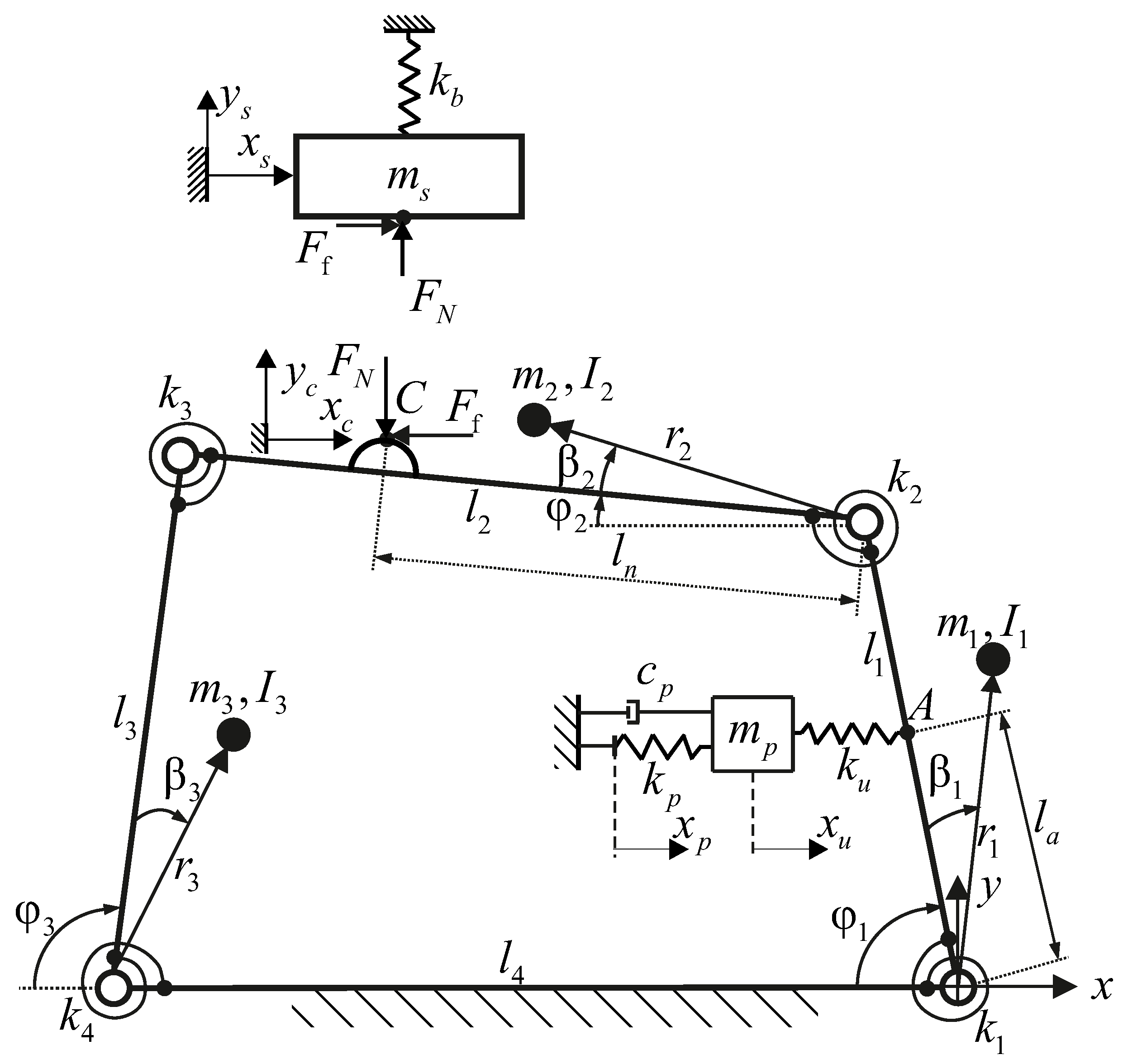
This study seeks to bridge the aforementioned gap by proposing a novel and unified dynamic modeling framework for flexure-based PSSAs. Unlike previous works that rely on lumped parameter models, our approach integrates a multi-domain representation encompassing rigid-body dynamics, flexural deformation, and non-linear friction behavior. Specifically, the dynamics of the slider and piezoelectric actuator are formulated using Newtonian mechanics. The flexure hinge mechanism is modeled using the PRBM in conjunction with the second-kind Lagrange equations, enabling an accurate capture of elastic deformation while preserving computational tractability. The frictional interaction between the slider and the guide surface is described using the LuGre dynamic friction model [
28], which allows for capture of both spring-like characteristics and velocity-dependent hysteresis effects.
To demonstrate the generalizability and effectiveness of the proposed methodology, we select a previously published flexure-based PSSA prototype introduced by Sun et al. [
18] as a representative case study. The integrated dynamic model is implemented and numerically simulated in MATLAB Simulink version 2021a, and its predictions are validated against experimental results reported in [
18]. Sensitivity analyses are performed to quantify the influence of critical design parameters, including the preload force, friction coefficient, tangential contact stiffness, flexure joint stiffness, center-of-mass positioning, and slider mass, on the actuator’s frequency–velocity performance.
The key contributions of this work are as follows:
We develop a comprehensive dynamic model of a flexure-based PSSA that rigorously captures the coupled dynamics of its constituent subsystems.
We introduce a hybrid modeling approach that combines PRBM, Newtonian dynamics, Lagrangian mechanics, and the LuGre friction model in a unified framework.
We provide a quantitative analysis of the effects of design parameters on dynamic behavior, offering valuable guidelines for actuator optimization.
We establish a generalized modeling strategy that can be readily extended to a wide variety of PSSA designs that employ flexure hinge mechanisms.
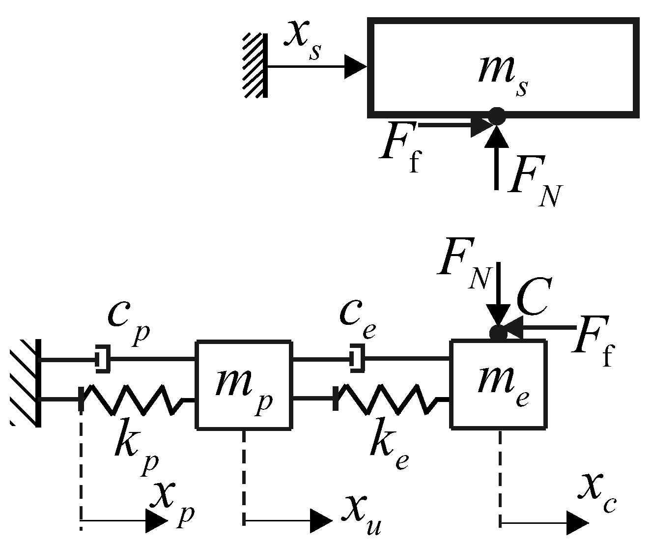
To further highlight the advantages of the proposed modeling approach, a simplified mass–spring–damper model (MSDM) is also developed and evaluated in parallel. This benchmark model, commonly adopted in prior studies, treats the flexure-based actuator as a lumped second-order system with equivalent stiffness and damping. By comparing simulation outcomes from both models under identical input conditions, we systematically assess modeling accuracy, computational efficiency, and sensitivity to design parameters.
This research provides a foundational step toward predictive modeling, design automation, and intelligent control of next-generation PSSAs. By highlighting the dynamic interdependencies within these systems, our work enables both researchers and engineers to achieve enhanced performance and reliability in micro-positioning applications.
3. Numerical Simulation and Validation
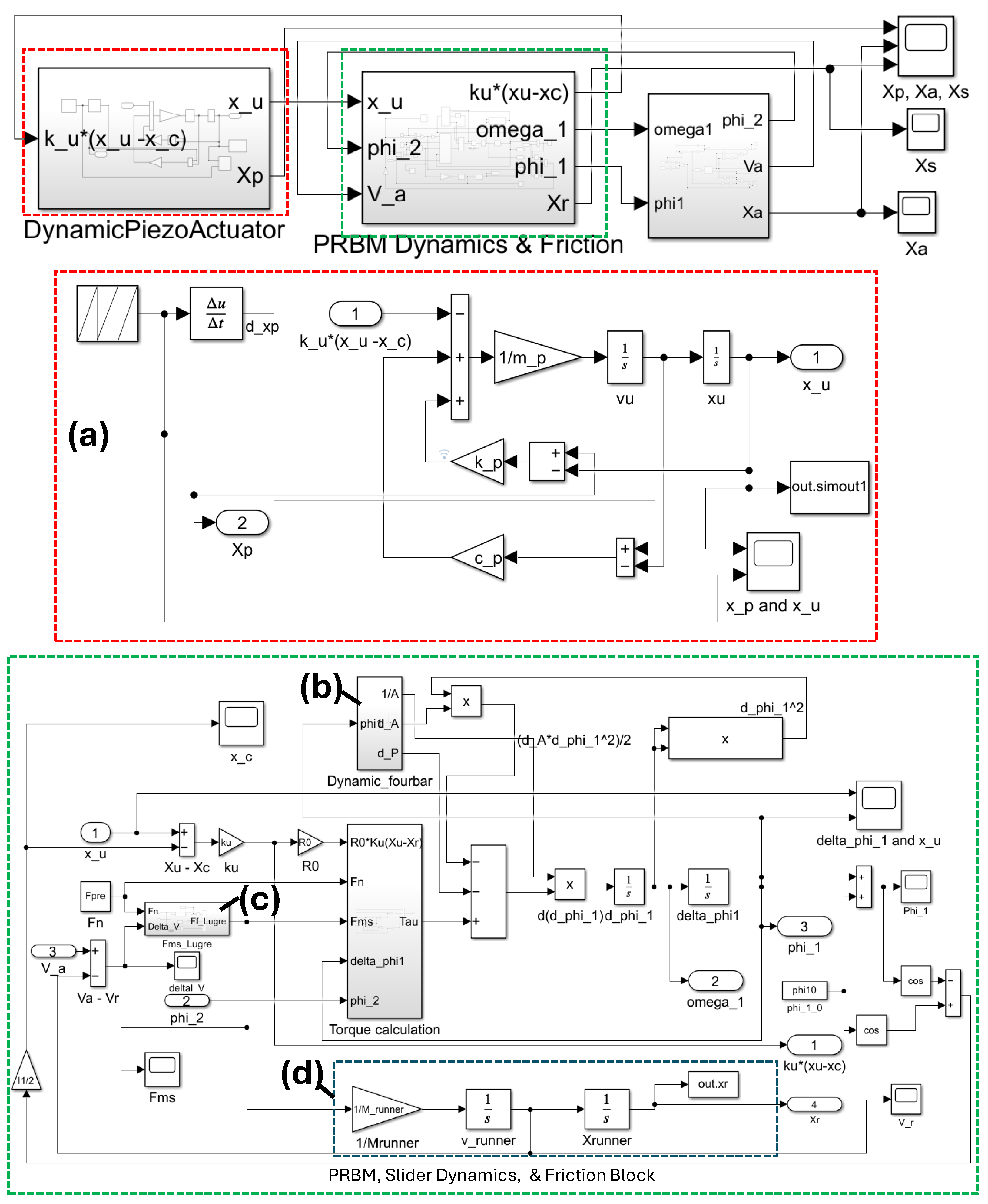
To simulate and validate these complex dynamics, a comprehensive numerical model was developed in MATLAB Simulink, as illustrated in
Figure 4. The Simulink model consists of four main subsystems: piezoelectric input, flexure compliance, LuGre friction, and load mass. The outputs include the displacements of the piezo stack (
), flexure point (
), and slider (
), together with velocity signals from which frequency–velocity responses are computed. Full simulation details are available upon request. Parameter values were carefully selected and, where applicable, derived from empirical data reported in [
18], ensuring realistic modeling fidelity. These are summarized in
Table 1,
Table 2,
Table 3 and
Table 4, and the simulation parameters are calculated and chosen as in
Table 2 for the LuGre friction model,
Table 3 for the piezo-element and the slider, and
Table 4 for the four-bar mechanism.
A fundamental aspect of the dynamic behavior of piezoelectric stick–slip actuators (PSSAs) is the presence of micro-vibrations that emerge immediately after the slip phase. These high-frequency oscillations are primarily induced by the rapid reversal in the deformation of the piezoelectric element, which dynamically interacts with the flexure hinge mechanism of the system and the frictional characteristics at the guiding interface. The interplay of these factors, namely, the inertia and compliance of the flexure structure, the piezoelectric actuation, and the stick–slip contact friction, governs the system’s transition into either stable or chaotic regimes.
When the actuator is driven at low excitation frequencies, the micro-vibrations are efficiently suppressed during the subsequent stick phase because of the inherent damping and frictional resistance. This leads to a periodic linear motion, and the system operates predictably and stably. In contrast, at higher driving frequencies, the residual micro-vibrations are no longer fully attenuated before the next actuation cycle begins. This incomplete damping causes cumulative oscillations that eventually result in chaotic motion of the slider, severely affecting positioning precision and system stability [
2,
33,
34,
36].
To characterize and visualize this phenomenon, dynamic simulations were performed at two representative frequencies, 1.5 kHz and 1.405 kHz, as shown in
Figure 5. At each frequency, both the displacement trajectories of the slider and the piezoelectric element, which depend on the time, are shown. In both cases of simulated frequency, residual micro-vibrations from the preceding cycle significantly influenced the starting condition of the subsequent cycle, thereby altering the net step length of the slider. The relative phase shift between the slider and the piezo-element was found to either augment or diminish the displacement per cycle, depending on their direction of motion. Specifically,
Figure 5a illustrates a case where opposing motions lead to a reduction in step length, while
Figure 5b shows a scenario in which aligned motions cause an increase.
The average velocity of the slider, which depends on frequency and step length, is determined by Equation (
27). Thus, if the step length is constant, the slider’s average velocity increases linearly with increasing driving frequencies. However, at high driving frequencies, the residual micro-vibrations lead to variances in the step length. As a result, the slider’s average velocity will be unstable if the micro-vibration is not fully suppressed within the following stick phase. Furthermore, when the driving frequency increases beyond a certain threshold, called the critical frequency, a slip between the slider and the contact element can appear even in the current stick phase. This slip will lead to a large decrease in the step length, and consequently in the slider’s average velocity. The critical frequency is determined based on two conditions, including no residual micro-vibrations at the end of the following stick phase and no slip within the current stick phase. It can be seen in
Figure 6,
Figure 7,
Figure 8,
Figure 9,
Figure 10,
Figure 11,
Figure 12,
Figure 13 and
Figure 14 below that, beyond the critical frequency, the slider velocity will be reduced.
For the analysis of the design parameters, several testing scenarios were performed. In the first scenario, a simulation with the same parameters as in [
18] was performed and compared with the experimental data. In other scenarios, some important design parameters are changed to evaluate their influence on the dynamic behavior of the whole system, expressed by the frequency–velocity dependence. For each of the following scenarios, only one parameter is changed while the other parameters remain the same as in the first scenario. The values in parentheses are the changing parameters used in the simulations. The changed parameters include the following: preload
, center of gravity position of each bar
, contact position
, slider mass
, tangential stiffness
, friction coefficient
, and stiffness of the flexure hinge
.
A series of simulation trials were performed to systematically assess the influence of these parameters on the dynamic performance of the system, with a specific focus on the velocity–frequency response as a diagnostic metric to identify transition thresholds between stable and chaotic operation. To validate the simulation results, the results were compared with the experimental data obtained from [
18].
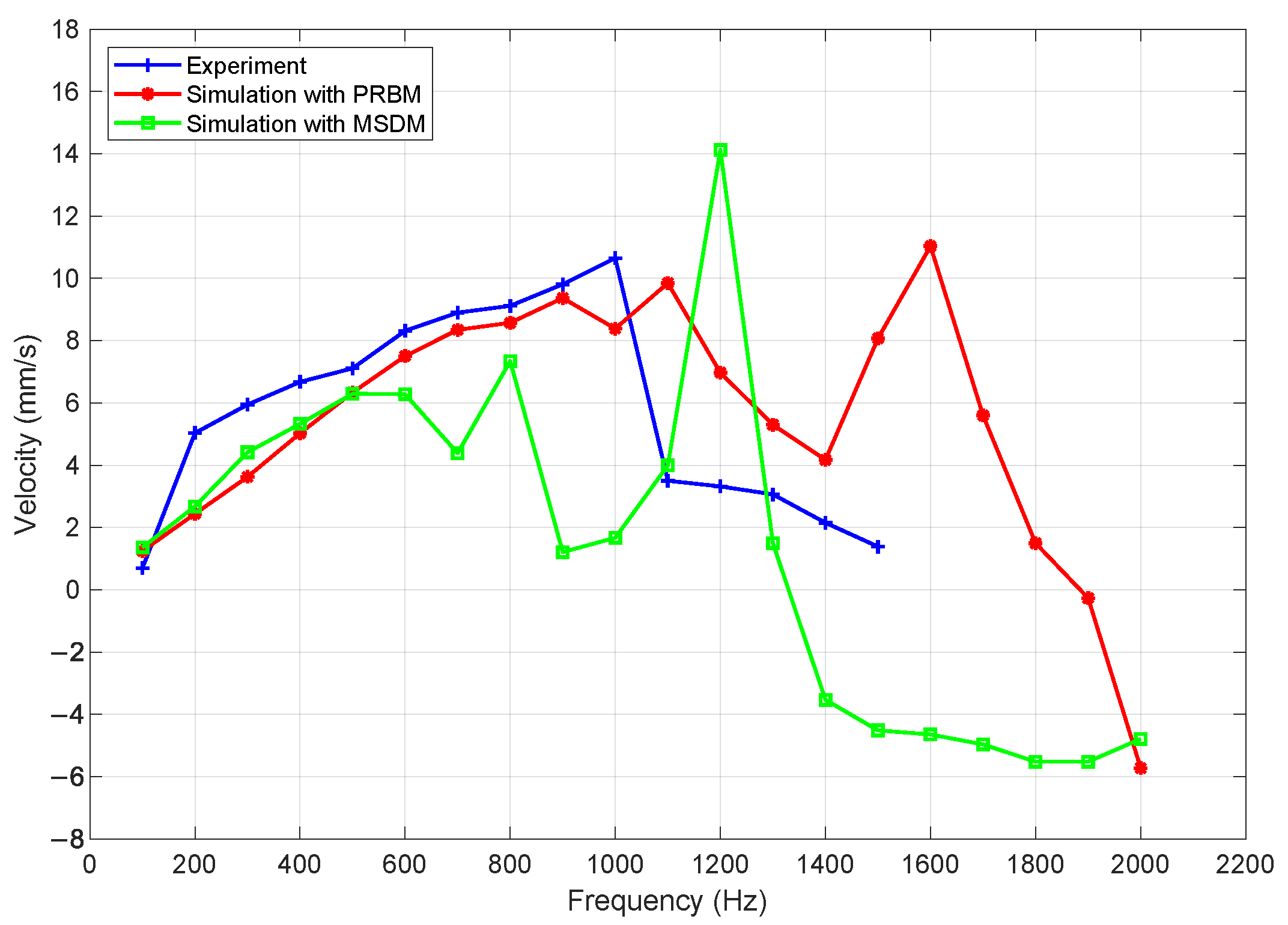
The measured and simulated slider velocities as functions of the driving frequency are presented in
Figure 6. In the experimental setup, the driving frequency was varied from 100 Hz to 1500 Hz in increments of 100 Hz. For the simulations, the frequency range was extended from 100 Hz to 2000 Hz using the same step resolution. The simulation results obtained using both the proposed PRBM and the MSDM are plotted alongside the experimental data for comparison. While validation is performed up to 1.5 kHz, simulations are extended to 2 kHz to illustrate the extrapolation capability of the model for potential future actuator designs. It is emphasized that results beyond 1.5 kHz are predictive in nature and not experimentally validated.
The simulation results obtained using the PRBM are analyzed and compared with the experimental data, as shown in
Figure 6. It is observed that, for frequencies below 900 Hz, the numerical simulation shows good agreement with the experimental results in terms of both trend and amplitude. In this frequency range, the frequency–velocity relationship exhibits predominantly linear behavior. This linearity can be explained by the fact that, at low driving frequencies, micro-vibrations are fully suppressed before the initiation of a new actuation cycle. As a result, the system remains stable without any chaotic behavior, and the step length of the slider remains constant. Consequently, the average velocity increases proportionally with frequency. In contrast, when the driving frequency exceeds 900 Hz, the time available in each cycle becomes too short to allow complete suppression of micro-vibrations. These residual micro-vibrations introduce instability into the system, which can lead to chaotic dynamics and cause the velocity response to become non-linear. Due to this non-linear nature, even a small change in the driving frequency can result in large, unpredictable variations in the slider’s velocity. Therefore, in practical applications, the device is typically operated within a frequency range where the frequency–velocity relationship remains linear to ensure predictable and stable performance. Moreover, at high frequencies, slipping can occur even during the stick phase due to the influence of residual micro-vibrations. This premature slip reduces the effective step length in each actuation cycle, resulting in a decrease in the average velocity of the slider. This explains why the velocity tends to decrease as frequency increases in this regime. The presence of such non-linear and chaotic behavior suggests that further model refinement is necessary to accurately capture the dynamics at high-frequency excitation.
It should be noted that the proposed framework has been validated against published experimental results [
18], ensuring its reliability without the need for additional prototype testing. Furthermore, the comparative analysis with the MSDM—commonly used in prior studies—reinforces the superior accuracy and adaptability of the proposed approach, highlighting its novelty and practical value.
The simulation results using the MSDM are also examined and compared with experimental data. As illustrated in
Figure 6, this model generally follows the same overall trend as the PRBM, capturing the linear frequency–velocity relationship at low frequencies. However, its accuracy is notably lower. Specifically, the MSDM only reliably replicates the linear behavior up to approximately 500 Hz, whereas the PRBM maintains good agreement up to 900 Hz. When comparing modeling accuracy, the MSDM exhibits a significantly larger deviation from the experimental results. A quantitative evaluation of the relative modeling error in the frequency range from 100 Hz to 1000 Hz reveals that the PRBM achieves a root mean square error (RMSE) of approximately
, while the MSDM results in a substantially higher error of around
.
This highlights the limited predictive capability of the MSD approach, particularly in capturing the dynamic response of the system beyond low-frequency excitation. The primary reason for this discrepancy lies in the fundamental simplicity of the MSDM. In this approach, the entire dynamics of the compliant four-bar mechanism are approximated using a lumped mass–spring–damper system. The dynamic parameters are estimated empirically through system identification techniques, rather than being derived from the actual structural and geometric properties of the mechanism. As a result, the model fails to capture the full range of dynamic behaviors exhibited by the real system, especially those influenced by the complex deformation characteristics of the flexure hinges. In contrast, the PRBM provides a more detailed and physically accurate representation of the mechanism. It incorporates essential design parameters of the compliant joints and better reflects the distributed flexibility and energy storage characteristics inherent in the structure. This enables the PRBM to more accurately simulate the system’s dynamic behavior across a wider frequency range. This distinction underscores the key advantage of the proposed PRBM-based modeling approach over simpler lumped-parameter alternatives, such as the MSDM.
It is important to note that the improved prediction accuracy of the PRBM is not merely a consequence of parameter fitting. To ensure a fair comparison, both the PRBM and MSDM models were initialized with identical parameter sets wherever possible. Key parameters such as the friction coefficients, preload force, and piezoelectric properties were derived directly from experimental data and reused consistently across both models. Only the lumped parameters required by the MSDM (i.e., equivalent stiffness, damping, and mass terms) were fitted separately, since these cannot be mapped structurally from the prototype geometry. Therefore, the superior performance of the PRBM should be attributed to its ability to capture flexure compliance, distributed stiffness, and non-linear stick–slip transitions with higher structural fidelity, rather than to differences in parameter mapping.
It should be noted that experimental uncertainties, such as sensor resolution, signal noise, and mechanical backlash, may slightly influence the RMSE values. Nevertheless, because the RMSE calculation spans multiple frequency points and both models are compared to the same experimental dataset, such errors do not alter the conclusion that the PRBM achieves a substantially lower modeling error than the MSDM.
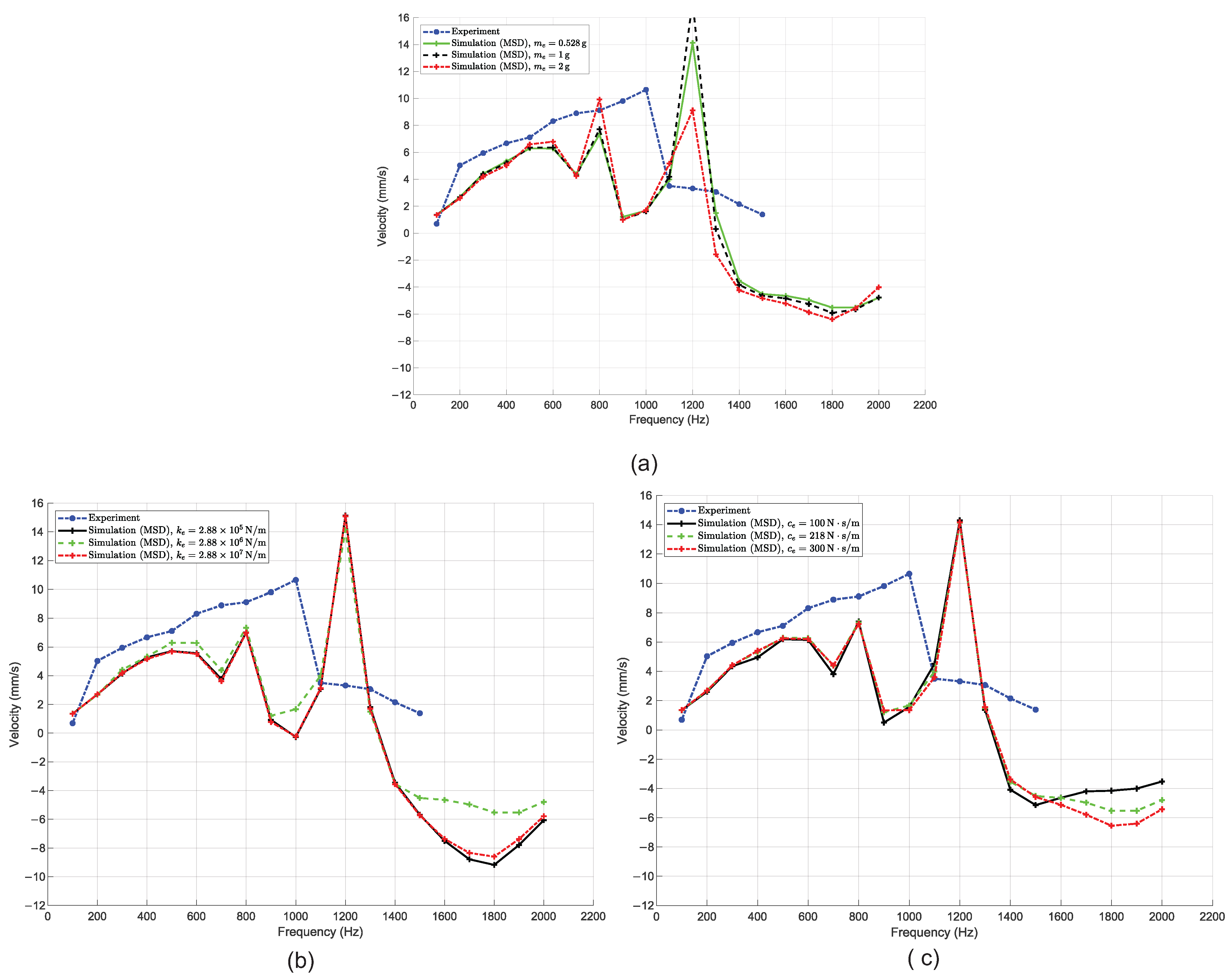
The three subfigures in
Figure 7 present a comparison between experimental data and numerical simulations using the MSDM under variations in three key parameters: the equivalent moving mass
, the equivalent stiffness coefficient
, and the equivalent damping coefficient
. The reason for investigating these three cases stems from the nature of the MSD modeling approach itself. When employing the MSDM, the real system is significantly simplified into an equivalent lumped model consisting of a mass, a spring, and a damper. The associated parameters are typically derived through a combination of dynamic system identification and engineering experience. The goal is to determine a reasonably optimal set of parameters that allows the simulation to approximate experimental behavior as closely as possible. However, in order to assess the sensitivity of the simulation results to each individual parameter, we deliberately varied them by approximately one order of magnitude above and below their nominal values. This allows us to observe how strongly the velocity–frequency response depends on each parameter and evaluate the robustness of the model.
From the results, it can be observed that varying the mass, stiffness, or damping values around the nominal set does not significantly change the general behavior of the simulation. The shape and trend of the velocity–frequency response remain relatively consistent across all three cases. These curves exhibit similar peaks, valleys, and non-linear characteristics, as previously seen in the simulation results with the baseline MSDM. While slight changes in amplitude and phase are present, they are not substantial enough to suggest high sensitivity. This finding reveals a key limitation of the MSD modeling approach. Since the model reduces a structurally complex and distributed-compliance mechanism into a simple lumped-parameter system, it lacks the fidelity to accurately reflect the nuanced effects of parameter variation. As a result, even significant changes to the mass, stiffness, or damping values yield limited variation in simulation outcomes. This reinforces the notion that while the MSDM may capture general trends, it lacks the precision and sensitivity needed for detailed dynamic analysis of compliant mechanisms.
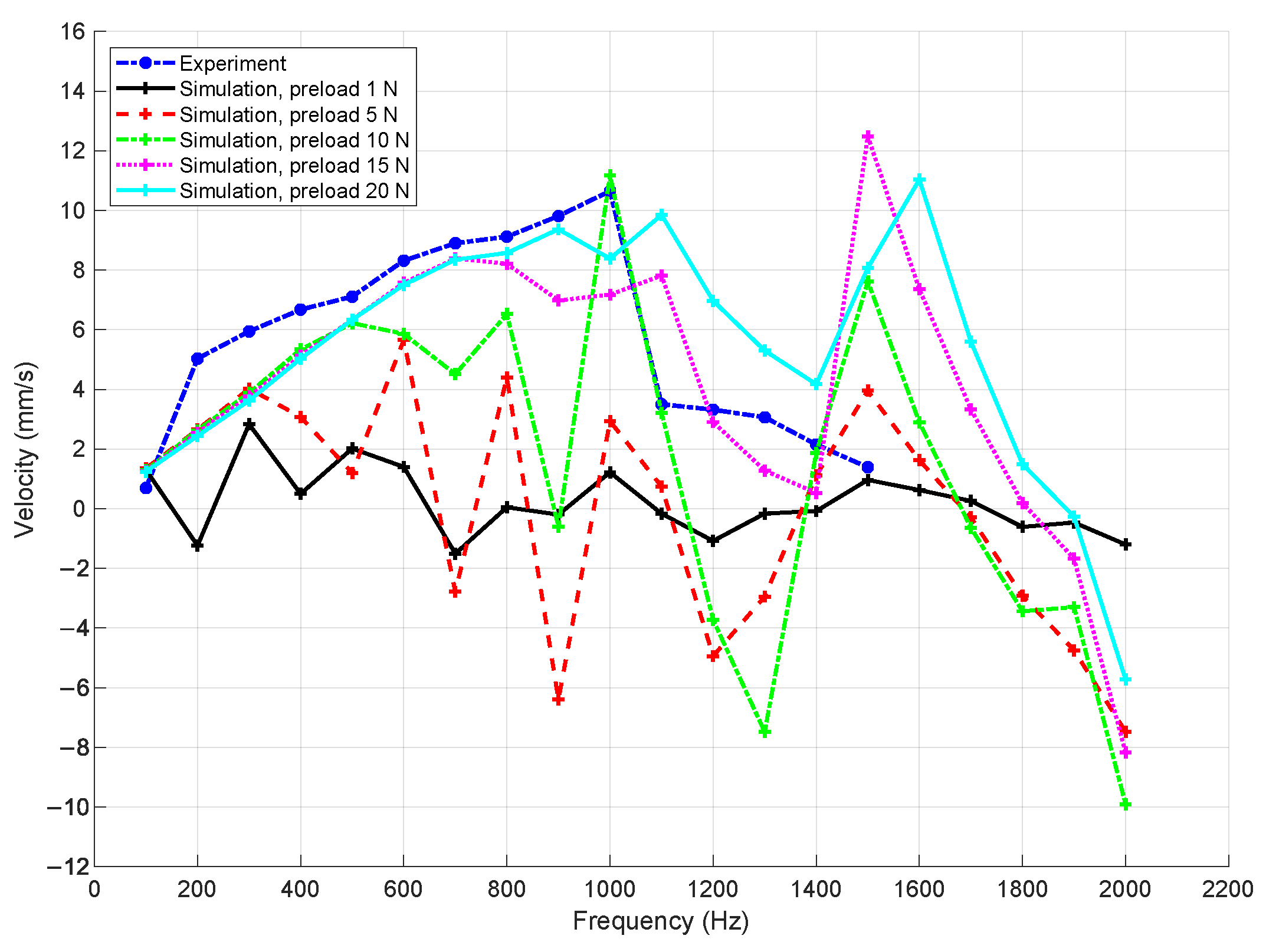
Preload is one of the key parameters that significantly affect the dynamic performance of the actuator. It plays a dual role: contributing to the generation of friction force and causing deformation in the overall system. On one hand, the friction force is essential for driving the slider; on the other hand, it helps suppress micro-vibrations. Therefore, the preload indirectly governs the velocity of the slider.
The relationship between the driving frequency and slider velocity under various preload values is shown in
Figure 8. In the numerical simulations, the preload was varied from 1 N to 20 N in increments of 5 N. At a low preload of 1 N, the system exhibits non-linear behavior even at low driving frequencies, with no clear linear trend in the velocity response. When the preload increases to 5 N, linear behavior is observed up to approximately 300 Hz, beyond which non-linearity dominates. As the preload is further increased to 10 N, 15 N, and 20 N, the linear response extends to higher frequencies of around 500 Hz, 700 Hz, and 900 Hz, respectively.
These simulation results show good agreement with the experimental data, validating the influence of the preload on the system dynamics. At small preload values, the corresponding friction force is insufficient to fully suppress micro-vibrations during the stick phase, even at relatively low frequencies, leading to chaotic behavior. As the preload increases, micro-vibrations are more effectively dampened, allowing the system to maintain linear behavior over a wider frequency range. However, beyond a critical frequency threshold, chaotic behavior emerges regardless of the preload level, resulting in unstable and unpredictable changes in slider velocity.
In addition to preload, the tangential contact stiffness
and the friction coefficients
(static) and
(kinetic) are key parameters that influence the frictional force and, in turn, the suppression of micro-vibrations during the stick–slip process. Their impact on the actuator dynamics is illustrated in
Figure 9 and
Figure 10.
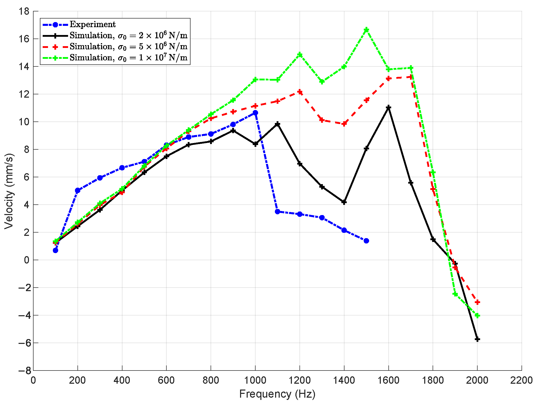
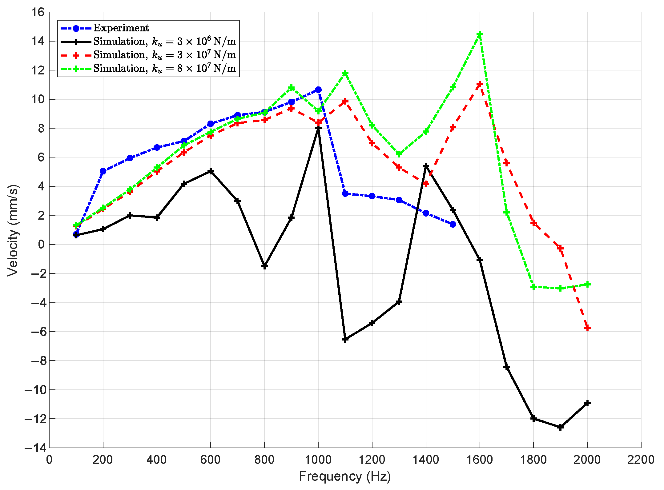
Figure 9 presents the simulated slider velocity responses for different values of tangential contact stiffness, specifically,
,
, and
. The results indicate that increasing
leads to an expansion of the linear regime in the frequency–velocity relationship. Higher tangential stiffness reduces micro-vibrations during contact transitions, enabling the system to maintain regular stick–slip motion over a broader frequency range. As a result, greater actuator velocities can be achieved at higher driving frequencies. This trend confirms the critical role of contact stiffness in governing the actuator’s dynamic response and optimizing its performance for high-speed applications.
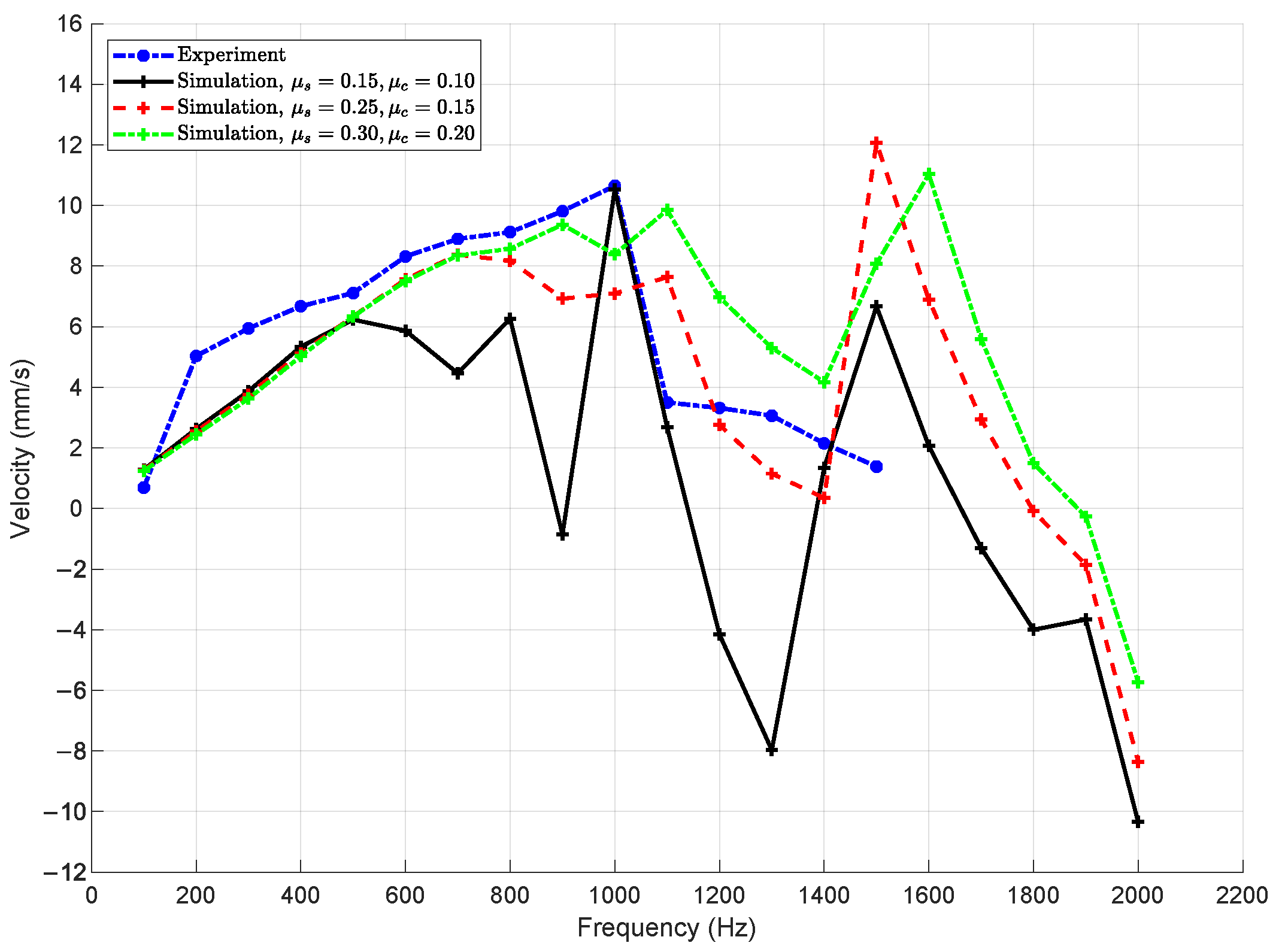
Figure 10 illustrates the effect of the friction coefficients on the dynamic response of the actuator. Numerical simulations were conducted for three combinations of static and kinetic friction coefficients:
,
, and
. The results indicate that increasing the friction coefficients significantly enhances the system’s ability to suppress micro-vibrations, leading to more stable slider motion over a broader frequency range.
Similar to the effect of preload, higher friction coefficients yield stronger frictional forces, which dampen chaotic oscillations during the stick–slip transitions. As a result, the actuator maintains linear velocity responses up to higher frequencies. However, beyond a certain frequency threshold, chaotic behavior emerges regardless of friction level, indicating intrinsic dynamic limits of the system. These findings reaffirm the critical role of frictional parameters in tuning the dynamic performance and stability of piezoelectric actuators.
The influences of the design parameters of the four-bar mechanism on the dynamic behavior of the actuator are validated through the simulation results presented in
Figure 11,
Figure 12 and
Figure 13. These results demonstrate a significant advantage of the proposed PRBM-based modeling approach: unlike conventional MSD methods, the PRBM allows for the incorporation of the geometric and material parameters of the flexure hinge mechanism directly into the model. This capability enables a detailed assessment of how individual design parameters affect the system’s dynamics, providing meaningful insights into structural optimization and performance enhancement. Such a feature aligns well with the objective of this study, which aims to establish a design-oriented dynamic model that bridges the gap between mechanical structure and system-level behavior.
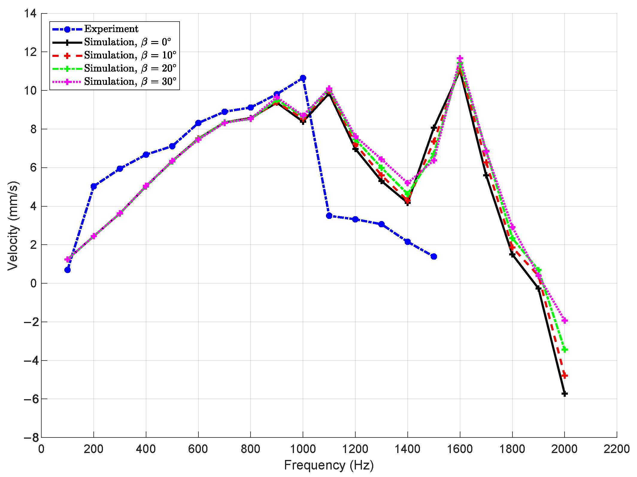
Figure 11 presents the simulation results for varying the position of the center of gravity of each bar in the four-bar mechanism, characterized by the parameter
(with
). The simulations were conducted with identical values of
and
applied across all bars. The influence of this parameter on the actuator’s dynamic behavior was evaluated through the frequency–velocity response curves.
The results reveal that in the low- to mid-frequency range (up to approximately 1200 Hz), the velocity curves for all cases are almost indistinguishable, indicating minimal sensitivity to the center of gravity position within this frequency range. As the driving frequency increases beyond 1200 Hz, slight deviations between the curves begin to emerge. However, these discrepancies remain small, and all simulations continue to follow a similar dynamic trend. This suggests that while the parameter may influence the local inertia distribution of the links, its effect on the overall slider motion is limited for the given mechanism and operating conditions.
This result further demonstrates the capability and advantage of the proposed PRBM-based modeling approach. Since the PRBM explicitly incorporates geometric and inertial parameters—such as the mass distribution and center of gravity—it allows for detailed assessment of individual design factors on system dynamics. This is a key advantage over simplified MSDMs, which cannot account for such structural influences. Consequently, PRBM provides a more comprehensive tool for design optimization and performance evaluation of compliant mechanisms.
The stiffness of the flexure joint, denoted as
, is a critical design parameter that directly influences the dynamic response of the compliant actuator.
Figure 12 presents a comparison between experimental measurements and simulation results obtained using different values of
, specifically
,
, and
. The parameter
corresponds to the stiffness of the soft joint connecting the piezoelectric actuator to the four-bar mechanism.
At the lowest stiffness value, , the simulation reveals highly unstable velocity responses, characterized by large oscillations and chaotic behavior even at moderate excitation frequencies. Irregular motion is evident from as low as 300 Hz, indicating that insufficient joint stiffness leads to inadequate constraint of the mechanism, resulting in poor transmission of actuation forces and diminished control over system dynamics.
In contrast, simulations performed with higher stiffness values, and , show significantly improved dynamic performance. The slider velocity remains stable and consistent across a broad frequency range up to 900 Hz, with pronounced resonance peaks observed near 1100–1300 Hz that closely match the experimental data. Among the tested values, yields the best agreement with experimental results, both in terms of amplitude and resonance location. The case with , while still stable, tends to overestimate velocity amplitudes and introduces secondary resonances not observed in the measurements.
These findings confirm that joint stiffness plays a decisive role in determining the actuator’s dynamic characteristics. A sufficiently high enhances system stability, improves the fidelity of actuation force transmission, and allows the mechanism to operate effectively under high-frequency excitation. Therefore, for reliable and predictable performance, the flexure joint must be designed with adequate stiffness that balances structural integrity with desired dynamic responsiveness.
The influence of the position of the contact point between the slider and the contact element attached to the four-bar mechanism—denoted by the parameter
—is evaluated and presented in
Figure 13. In the simulations,
is varied from 0 mm to 15 mm in increments of 5 mm. The results indicate that changes in
have negligible impact on the slider’s velocity within the linear frequency range, particularly for excitation frequencies below 900 Hz. In this region, the velocity–frequency curves for all values of
closely overlap, suggesting that the position of the contact point does not significantly affect the dynamic behavior of the system. At higher frequencies beyond 900 Hz, minor discrepancies begin to emerge among the curves. These variations may be attributed to changes in the effective moment arm introduced by altering the contact point position, which could slightly affect the force transmission and energy dissipation during dynamic interaction. Nevertheless, the overall influence remains limited compared to other design parameters, such as the joint stiffness or preload. This outcome reinforces the strength of the PRBM modeling framework, which allows detailed investigation of geometric parameters like
. Such analysis is not feasible with lumped-parameter models (e.g., MSD models), which abstract away structural geometry. Hence, the PRBM approach proves advantageous in evaluating the sensitivity of actuator performance to specific design features and supports design-oriented simulation analysis aligned with the objective of this study.
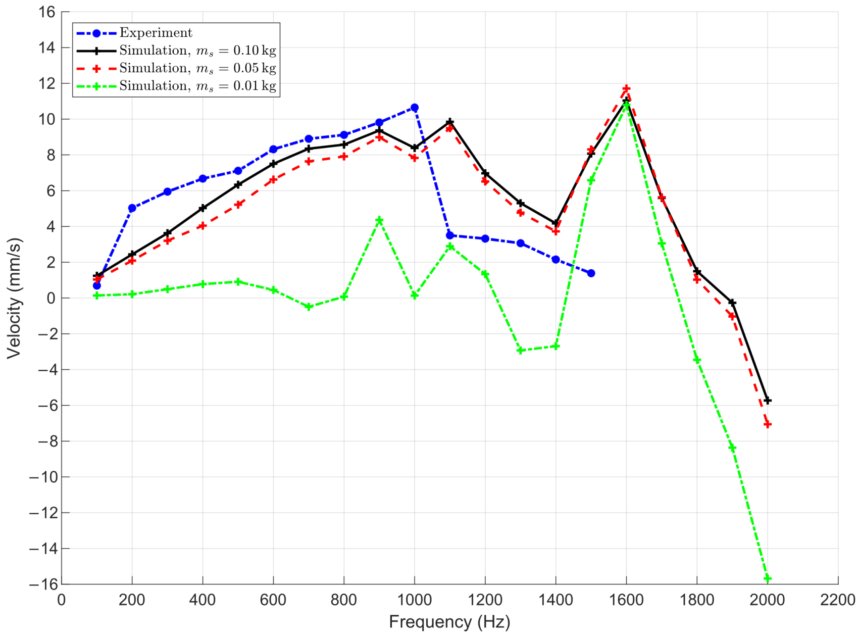
The effect of slider mass
on the dynamic behavior of the actuator is illustrated in
Figure 14. Simulations were carried out for three different masses:
,
, and
. The results show that a small slider mass of
leads to significant instability and reduced average velocity across the entire frequency range. This behavior is attributed to insufficient inertial force during the slip phase, which increases the susceptibility to backward motion and chaotic dynamics.
In contrast, with higher slider masses ( and ), the system maintains more stable performance with higher velocities, particularly in the range from 600–1800 Hz. The curves for these two masses closely match the experimental data, indicating that above a certain threshold, the influence of mass becomes negligible.
These findings highlight the importance of appropriate mass selection in actuator design. While excessively small mass degrades performance, moderately higher masses improve dynamic stability without adversely affecting velocity output.
Discussion of sensitivity results
The quantitative sensitivity analysis presented in
Table 5 clarifies the relative impact of key design parameters on the actuator’s dynamic performance. Among all factors, the preload force
exerts the strongest effect, with a sensitivity of about +15% per 10% change. This finding reflects its dual role: providing sufficient normal force to sustain stick–slip motion while simultaneously suppressing micro-vibrations, thereby extending the actuator’s linear operating range toward higher frequencies.
The friction pair also shows a significant positive sensitivity of approximately +10%. Increasing both the static and kinetic friction coefficients enhances damping at the contact interface, which broadens the frequency range over which stable and linear velocity responses are achieved. This indicates that properly tuned friction improves system robustness without overly compromising step length.
The tangential contact stiffness contributes a moderate effect, with an estimated sensitivity of +8%. A stiffer tangential contact reduces residual vibrations during transitions between stick and slip, enabling the system to maintain linearity and achieve higher velocities under elevated excitation frequencies. Similarly, the flexure joint stiffness demonstrates a sensitivity of about +12%. Notably, too low a stiffness induces chaotic motion and unstable transmission, while the nominal value of N/m yields the closest match with experimental data, highlighting the existence of an optimal stiffness threshold.
In contrast, geometric and inertial parameters, such as the mass distribution angle , slider mass , and contact position , have negligible impact, with sensitivities below 2–5%. Small slider masses (∼0.01 kg) may destabilize the system, but within practical ranges, variations in these parameters do not significantly shift the linear regime frequency limit.
Overall, the results establish a clear hierarchy of influence: preload force, joint stiffness, and tangential stiffness dominate actuator dynamics, while frictional parameters provide additional stabilization. Geometric factors such as , , and exert only minor effects. These findings demonstrate the predictive capability of the PRBM–LuGre model, which not only captures overall system behavior but also quantifies parameter sensitivities, thereby guiding structural optimization and performance enhancement of flexure-hinge-based stick–slip actuators.
Performance evaluation
Table 6 compares the computational performance of three dynamic modeling approaches for compliant mechanisms: the MSDM, the Standard PRBM, and our Enhanced PRBM. The comparison is based on simulation time under different time-step resolutions, alongside their accuracy relative to experimental data.
In the Standard PRBM, the system dynamics are formulated using the Lagrangian method (Equation (
1)). Kinetic and potential energies and their derivatives with respect to the generalized coordinate
are evaluated through Simulink functions and symbolic operations. While this ensures high accuracy, it incurs substantial computational overhead, especially at small time steps, where symbolic processing dominates runtime.
The Enhanced PRBM preserves the same modeling fidelity but improves computational efficiency by analytically reformulating the governing equations. Closed-form expressions are derived for the dynamic inertia coefficient
(Equations (
4)–(
6)) and potential energy terms, removing the need for symbolic computation. This reformulation enables faster simulations while maintaining identical accuracy to the Standard PRBM.
All simulations were conducted in MATLAB 2021a on a workstation with a 12th Gen Intel(R) Core(TM) i7-12700 CPU and 64 GB of RAM. Results confirm that MSDM runs the fastest due to its simplicity but suffers from high error (≈51.65%), limiting its predictive capability. Both PRBM approaches deliver accurate results (≈20.19% RMSE vs. experiment). However, the Standard PRBM requires over 3900 s to complete a run at s and fails at s, while the Enhanced PRBM completes the same simulations in just 1.185 s and 11.067 s, respectively.
These findings demonstrate that the Enhanced PRBM combines the accuracy of a full compliant mechanism model with computational efficiency one to two orders of magnitude faster than the Standard PRBM. This makes it particularly suitable for high-resolution dynamic analyses and scenarios requiring fine time-step resolution or near real-time performance.
Comparison of modeling strategies
Table 7 compares three major modeling strategies—FEA, MSDM, and the proposed Enhanced PRBM—based on their capabilities in dynamic analysis of compliant piezoelectric actuators. Each method exhibits distinct advantages and limitations.
Finite element analysis (FEA) provides the highest structural fidelity, capable of resolving detailed stress fields, local contact interactions, and modal responses. It can, in principle, perform transient dynamic simulations and parametric studies. However, these analyses are computationally expensive and become impractical when wide frequency sweeps or multi-parameter optimizations are required. Consequently, while FEA is valuable for validating structural integrity or local compliance, it is less suited for efficient system-level dynamic modeling.
In contrast, the mass–spring–damper model (MSDM) is computationally efficient and easy to implement for control design. Yet, its reliance on lumped parameters makes it structurally inconsistent. Flexure hinges are approximated by equivalent spring–damper elements, preventing the model from capturing non-linear geometric effects or assessing the direct influence of structural parameters. As a result, MSDM offers only qualitative agreement with experiments and lacks predictive capability for design optimization.
The proposed Enhanced PRBM offers a balanced alternative by combining structural fidelity with computational efficiency. Unlike MSDM, it explicitly incorporates the geometric and material properties of the flexure hinges, while avoiding the heavy computational load of FEA. Through analytical reformulation, the Enhanced PRBM retains the accuracy of the standard PRBM but runs orders of magnitude faster, enabling dynamic simulations, parametric sweeps, and sensitivity studies within practical time scales. This makes it particularly well suited as a design-oriented tool, bridging the gap between detailed structural modeling and efficient system-level prediction.
Overall, the comparison underscores that while FEA remains indispensable for local structural verification and MSDM for rapid prototyping, the Enhanced PRBM provides the most effective framework for dynamic analysis and optimization of compliant stick–slip actuators.
This section presents a comprehensive investigation into the influence of preload, contact properties, and structural design parameters on the dynamic performance of piezoelectric actuators. Through systematic simulations based on the pseudo-rigid-body model (PRBM), validated against experimental data, the study reveals the key factors that govern the stability, linearity, and transition to chaotic behavior in slider motion. The results underscore the critical role of preload and tangential contact stiffness in extending the frequency range over which the actuator can operate efficiently. Simultaneously, variations in friction coefficients are shown to significantly affect micro-vibration suppression and enable higher velocity responses at increased driving frequencies. In contrast, changes in the mass distribution (via center of gravity position), contact point location, and even slider mass (above a minimum threshold) exhibit relatively minor influence on system behavior within the linear regime. These insights highlight the advantage of the PRBM framework in capturing the nuanced effects of structural parameters and support its application in the design-oriented optimization of compliant, friction-driven actuators.

