1. Introduction
Permanent magnet (PM) electric machines have garnered significant attention in modern electromechanical applications due to their inherent advantages over traditional machines. These advantages include the elimination of field winding losses, simplified construction, enhanced efficiency, and increased torque density [
1]. The use of permanent magnets results in a consistent magnetic flux density across the air gap, contributing to improved dynamic performance [
2]. BLDC motors, which utilize permanent magnets for magnetic field excitation, have become widespread in applications such as electric vehicles (EVs) [
3,
4,
5], industrial compressors, and aerospace systems [
6,
7]. Their popularity is driven by reduced mechanical losses, lower maintenance requirements, and higher reliability. By 2030, electric machines are expected to replace traditional induction motors across various industries [
8]. Furthermore, the global demand for electric machines is projected to reach USD 15.2 billion by the end of 2025, driven by continued industrial expansion and technological advancements [
9,
10,
11].
Several methodologies are proposed for the parameter identification of the BLDC motors, ranging from simple offline experimental techniques to more complex model-based approaches and optimization algorithms [
12]. For example, resistance and inductance are measured using voltage–current relations under static conditions, while the back-EMF constant is typically estimated by operating the motor in generator mode and analyzing the voltage–speed characteristics [
13]. Kumpanya et al. present a study on parameter identification of BLDC motors using metaheuristic optimization techniques. The authors employ Adaptive Tabu Search (ATS) and Intensified Current Search (ICS) algorithms to estimate key motor parameters by minimizing the error between experimental and simulated speed data. Their approach demonstrates improved accuracy and efficiency in parameter estimation, highlighting the effectiveness of metaheuristic methods in motor modeling [
14]. Xiang et al. develop a practical system identification method for BLDC motors using only rotor speed and armature current data. Their approach combines frequency and time domain techniques to accurately estimate motor parameters, including nonlinear effects like cogging torque. Validation through experiments shows high model accuracy, providing a solid basis for advanced BLDC motor control design [
15].
In addition to parameter identification, Majdoubi et al. develop a method that combines acceleration and deceleration tests with a weighted recursive least squares algorithm to estimate BLDC motor parameters, including rotor inertia and electrical characteristics. The results validate the method’s accuracy for control applications through simulation [
16]. Similarly, Jimenez-Gonzalez et al. propose a method based on electromechanical testing and a standard RLS algorithm to estimate BLDC motor parameters. Their experimental validation confirms the accuracy of the identified values, demonstrating the method’s applicability for model-based control and dynamic analysis [
2]. Marcos-Andrade et al. propose an online algebraic estimation method for identifying parameters and disturbances in BLDC motors. The approach enables real-time estimation of key motor parameters and external disturbances without requiring a detailed motor model. Experimental results demonstrate the method’s effectiveness in enhancing control accuracy and robustness under varying operating conditions [
8]. Yang et al. develop a dynamic energy model and a two-stage RLS method for online parameter identification in permanent magnet synchronous motor (PMSM) driven belt conveyors. Their approach enhances accuracy and convergence by accounting for load variations and operating conditions. Hardware in the loop simulations validate the method’s effectiveness and robustness against measurement noise [
17]. In contrast, Khan et al. present a data-driven system identification approach for BLDC motors using least-squares estimation and NARX neural networks. Their study compares linear and nonlinear modeling techniques to accurately capture motor dynamics. Results show that the NARX-based model outperforms traditional methods in prediction accuracy and adaptability, making it well suited for advanced control and diagnostic applications [
18]. Li and Jian present an advanced hybrid optimization algorithm, known as the Chaotic Gaussian–Cauchy Rao-1 (CGCRAO), which combines chaotic mapping with Gaussian and Cauchy variation strategies to improve parameter identification in electric machines. Although applied to PMSMs, the method shows high accuracy and fast convergence, making it adaptable to BLDC motor applications [
19].
A wide range of control techniques is also suggested for BLDC motors, including PID and fuzzy logic controllers, artificial neural networks, genetic algorithm optimization, and sliding mode control [
20,
21,
22,
23]. These control schemes are developed to regulate or track rotor position, speed, or torque based on application requirements. Moreover, Kamde and Morey propose a speed control strategy for BLDC motors using a PI controller optimized through the Particle Swarm Optimization (PSO) algorithm. This approach enhances transient performance by reducing overshoot, steady-state error, and settling time. Simulation results in MATLAB/Simulink demonstrate that PSO-based tuning significantly outperforms conventional Ziegler–Nichols methods in terms of control accuracy and overall system stability [
24].
Recent studies on advanced control strategies for BLDC motors highlight various effective methods for improving speed regulation and dynamic performance. For instance, Shenbagalakshmi et al. propose a fuzzy logic–based speed control strategy for BLDC motors in electric vehicles that achieves faster response, smoother speed transitions, and eliminates steady-state error under variable load conditions, significantly outperforming conventional PID controllers in accuracy and stability [
25]. Similarly, Çelik and Karayel develop an effective speed control strategy for BLDC motors using a cascade 1PDf–PI controller, with parameters tuned by the Snake Optimizer algorithm. Their method improves dynamic performance and minimizes speed error under varying load conditions. Simulation results show superior accuracy and faster response compared to conventional controllers [
26]. In addition, Hafidh et al. propose a speed control enhancement strategy for BLDC motors in small electric vehicles by incorporating a Zeta converter. The system improves voltage regulation and dynamic response under varying load conditions. Simulation results show better speed stability, reduced overshoot, and the ability to maintain speed within a ±10% error margin under rated torque levels, making the setup suitable for low-power electric vehicle applications [
27]. Furthermore, Arivalahan et al. propose a hybrid control strategy combining Radial Basis Function Neural Network and Student Psychology Optimization Algorithm (RBFNN-SPOA) to tune PID controller parameters for BLDC motor speed regulation. The method improves dynamic response by reducing overshoot, achieving fast settling time, and minimizing steady-state error [
28].
Building on these developments, recent studies also present several advanced control strategies aimed at enhancing the robustness and precision of electric motor drives, particularly for PMSMs, which exhibit control challenges similar to those of BLDC motors. For example, an observer-based control scheme using a data-driven Radial Basis Function (RBF) neural network is proposed to achieve prescribed performance in PMSM speed regulation, offering improved adaptability and tracking accuracy in the presence of nonlinearities and uncertainties [
29]. In another study, a model-free current predictive control method is developed based on an ultralocal model, integrating a fixed-time observer and an extremum-seeking algorithm to enable fast convergence and model-independence [
30]. Additionally, observer-based fixed-time controllers are introduced to address parameter uncertainties in PMSMs, ensuring finite-time stability and robustness under dynamic operating conditions [
31]. Furthermore, autotuned nonlinear extended-state observers (NESOs) are employed within fixed-time control frameworks for servo motor systems, significantly improving transient response and disturbance rejection capabilities [
32]. While these techniques are primarily applied to PMSMs, their potential applicability to BLDC motor control is evident, particularly in scenarios requiring high performance under uncertainty or variable load conditions. The integration of such observer-based and intelligent control strategies represents a promising direction for future development in BLDC motor applications.
To address these gaps in the literature, this study presents a comprehensive modeling and control approach for a small-scale BLDC motor. A transfer function model is experimentally derived using identified electrical, mechanical, and electromagnetic parameters, ensuring accurate representation of the motor’s dynamics. Building on this model, a conventional PI controller combined with a low-pass filter (LPF) is designed to achieve smooth and responsive speed control. The proposed control strategy is validated through real-time implementation and experimental testing. Unlike previous studies that rely solely on simulations, this work offers a complete framework that bridges modeling, identification, and real-time control, thereby contributing both theoretical and practical insights to the field. The main contributions of this paper are as follows:
Complete experimental identification of the electrical, mechanical, and electromagnetic parameters of a small-scale BLDC motor using a controlled test setup and an AVL dynamometer.
Development of a transfer function model based on the identified parameters to accurately represent the motor’s dynamic behavior.
Validation of the model through comparisons between MATLAB/Simulink simulations and real-time experimental results under various input profiles, including exponential and sinusoidal waveforms.
Design and implementation of a conventional PI controller integrated with an LPF to enhance speed control performance by reducing high-frequency noise and improving transient response.
Real-time experimental demonstration of the effectiveness and robustness of the proposed closed-loop control system under varying operating conditions.
The rest of this paper is organized as follows.
Section 2 presents the mathematical model of the BLDC motor, including its electrical and mechanical components.
Section 3 describes the experimental setup and methodology, covering parameter identification procedures, MATLAB/Simulink implementation, and the design of a PI controller.
Section 4 discusses the experimental results, including model validation using various input profiles and speed regulation performance under fixed and variable speed conditions. Special emphasis is placed on the impact of integrating an LPF into the control loop to enhance the transient response and reduce overshoot and delay. Finally,
Section 5 concludes the study and outlines potential directions for future work.
3. Materials and Methods
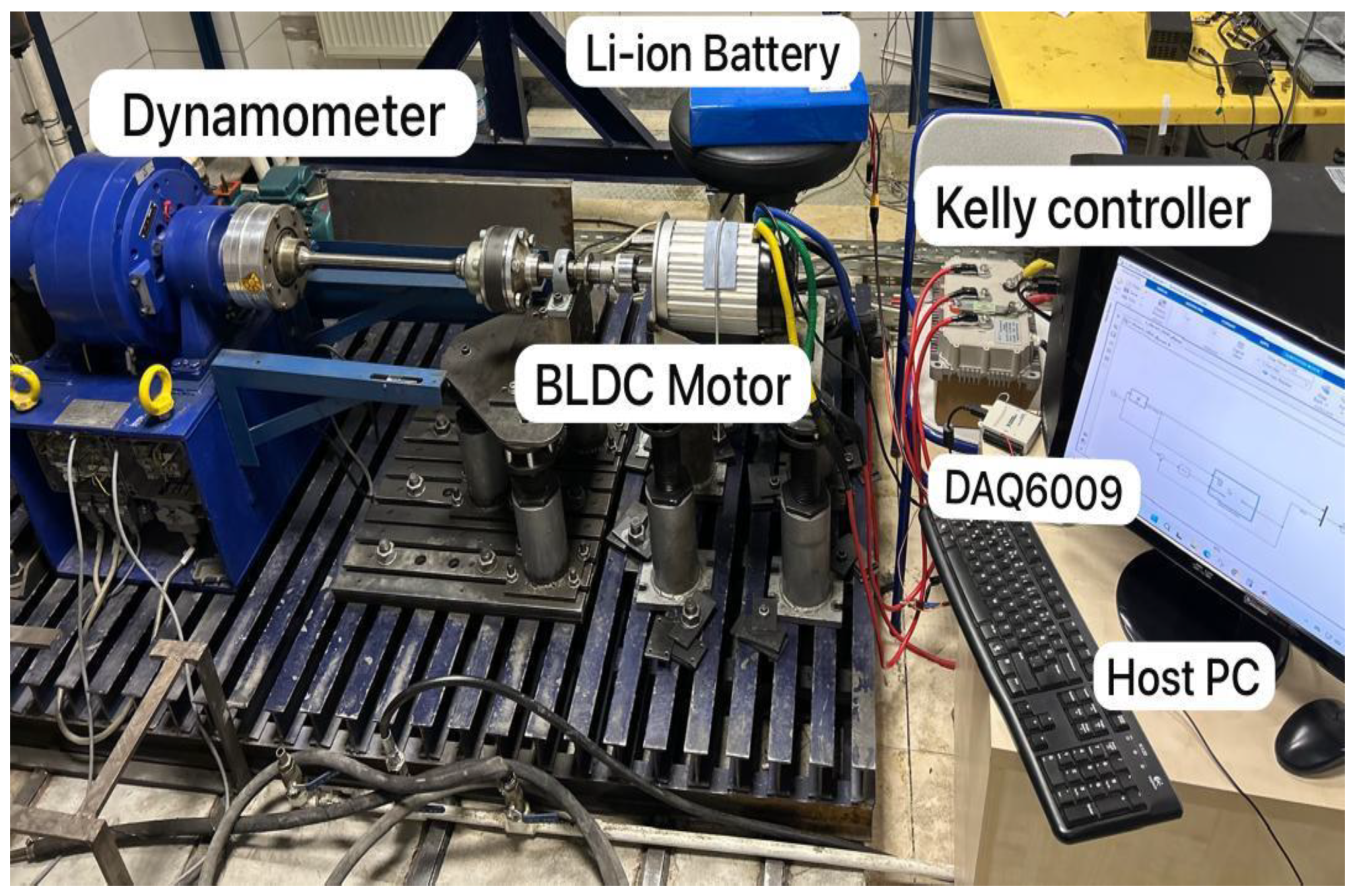
Figure 2 shows the complete experimental setup used in this study. The system consists of a 2.2 kW three-phase BLDC motor, whose detailed specifications are provided in
Table 1. A Kelly KLS12301-8080I motor controller (Kelly Controller Inc., Shanghai, China) was employed to drive the motor and monitor key parameters such as motor speed, battery voltage, and current. The controller was configured through its proprietary software interface to operate in speed control mode using a 0–5 V analog throttle input. Key input parameters included current limits, maximum speed, number of motor poles, and protection settings such as undervoltage cutoff and regenerative braking.
A data acquisition (DAQ) device (USB-6009, National Instruments, Austin, TX, USA) was used solely to generate and transmit the analog control signal that served as the throttle input to the Kelly KLS12301-8080I controller. The analog voltage signal (0–5 V), generated in MATLAB/Simulink using the Data Acquisition Toolbox, was used to set the reference speed of the BLDC motor. Although the NI USB-6009 has measurement capability, this functionality was not utilized in the present study. Instead, the device functioned purely as a control interface, enabling real-time implementation of speed commands during experimental testing.
A 60 V, 17.4 Ah, 16S-6P Li-ion battery pack (Aspilsan Enerji A.Ş., Kayseri, Türkiye) supplied stable DC power to the motor-controller system. MATLAB/Simulink functioned as the central control unit, executing control algorithms and interfacing with both the DAQ and the motor controller.
The eddy-current dynamometer (AVL List GmbH, Graz, Austria) operates based on the principle of electromagnetic induction. When the motor drives the dynamometer shaft, it causes a metal disc or rotor inside the dynamometer to rotate within a magnetic field. This interaction induces eddy currents in the rotor, which generate a resistive torque opposing the rotation. The magnitude of this braking torque can be precisely controlled by adjusting the magnetic field strength. The resulting torque and rotational speed are measured in real time using integrated sensors. In this study, the dynamometer served as a reliable speed reference source during back-EMF constant estimation and inertia measurement tests. Additionally, a digital multimeter, an AC power supply, and a DC power supply were employed during individual resistance, inductance, and back-EMF constant tests.
3.1. Parameter Identification
3.1.1. Phase Resistance and Inductance
To measure the phase resistance, a variable DC voltage is applied across two motor phases while the rotor remains stationary. The resulting current is recorded, and the phase resistance is calculated using Ohm’s law. On the other hand, the phase inductance can be measured by applying a variable AC voltage across two motor phases. After recording the applied voltage and the corresponding current, the impedance of the motor can be calculated using the following Equation (6):
Assuming the motor behaves as a series
circuit, the impedance is related to the resistance
and inductive reactance
as follows:
The inductive reactance
can then be determined as follows:
Finally, the phase inductance
L of the BLDC motor is calculated using the following relation:
where
is the frequency of the applied AC voltage, expressed in hertz (Hz).
3.1.2. Back EMF Constant
To determine the back EMF constant
of the BLDC motor, the motor is operated as a generator by mechanically coupling it to a dynamometer. By varying the rotational speed and measuring the resulting open-circuit voltage
and angular velocity
, the back EMF constant can be computed using the following Equation (10):
where
indicates the back EMF constant of the motor.
Additionally, to determine the number of poles in the BLDC motor, the steady-state angular frequency (
of the induced voltages is computed, then the number of poles can be calculated using Equation (11), as follows:
where
denotes the number of pole pairs of the motor and
represents the steady-state angular frequency. The steady-state rotor speed measurement is indicated as
.
3.1.3. Moment of Inertia of the BLDC Motor
The rotor inertia of the BLDC motor was measured by using a deceleration method; this method involves measuring the motor’s deceleration rate when power is cut off, and then using the relationship between torque, inertia, and angular acceleration as in Equation (12).
where
denotes the torque in (N.m) and
is the angular acceleration in
.
Finally, the estimated parameters will be substituted into Equation (5) to obtain the transfer function of the BLDC motor at no load.
3.2. MATLAB/Simulink Simulation and Experimental Comparison
The identified transfer function of the BLDC motor was implemented in MATLAB/Simulink for validation. During this stage, sinusoidal and exponential input signals were applied to both the model and the BLDC motor in order to enable a smooth and controlled comparison between simulated and experimental responses. These continuous waveforms facilitated accurate evaluation of the transfer function without introducing abrupt transients that could lead to nonlinear effects or excessive current surges in the open-loop configuration. In contrast, step input signals were later utilized during the closed-loop control experiments, specifically as reference speed commands, to assess the controller’s ability to track sudden changes in speed. This approach allowed for a comprehensive evaluation of the system’s tracking performance under practical operating conditions.
3.3. PI Controller Implementation
A classical PI controller was implemented in MATLAB/Simulink for closed-loop speed regulation of the BLDC motor. The controller parameters were tuned using a trial-and-error approach based on observed system behavior. Experimental testing was conducted to validate the performance of the control system. To further enhance the stability and robustness of the system, a first-order LPF that was integrated into the control loop. This addition helped attenuate high-frequency noise and contributed to improved transient response characteristics, including reduced overshoot, faster rise time, and lower steady-state error.
The mathematical model of the LPF is:
where
denotes the time constant in seconds.
4. Results and Discussion
4.1. Parameter Identification Procedures
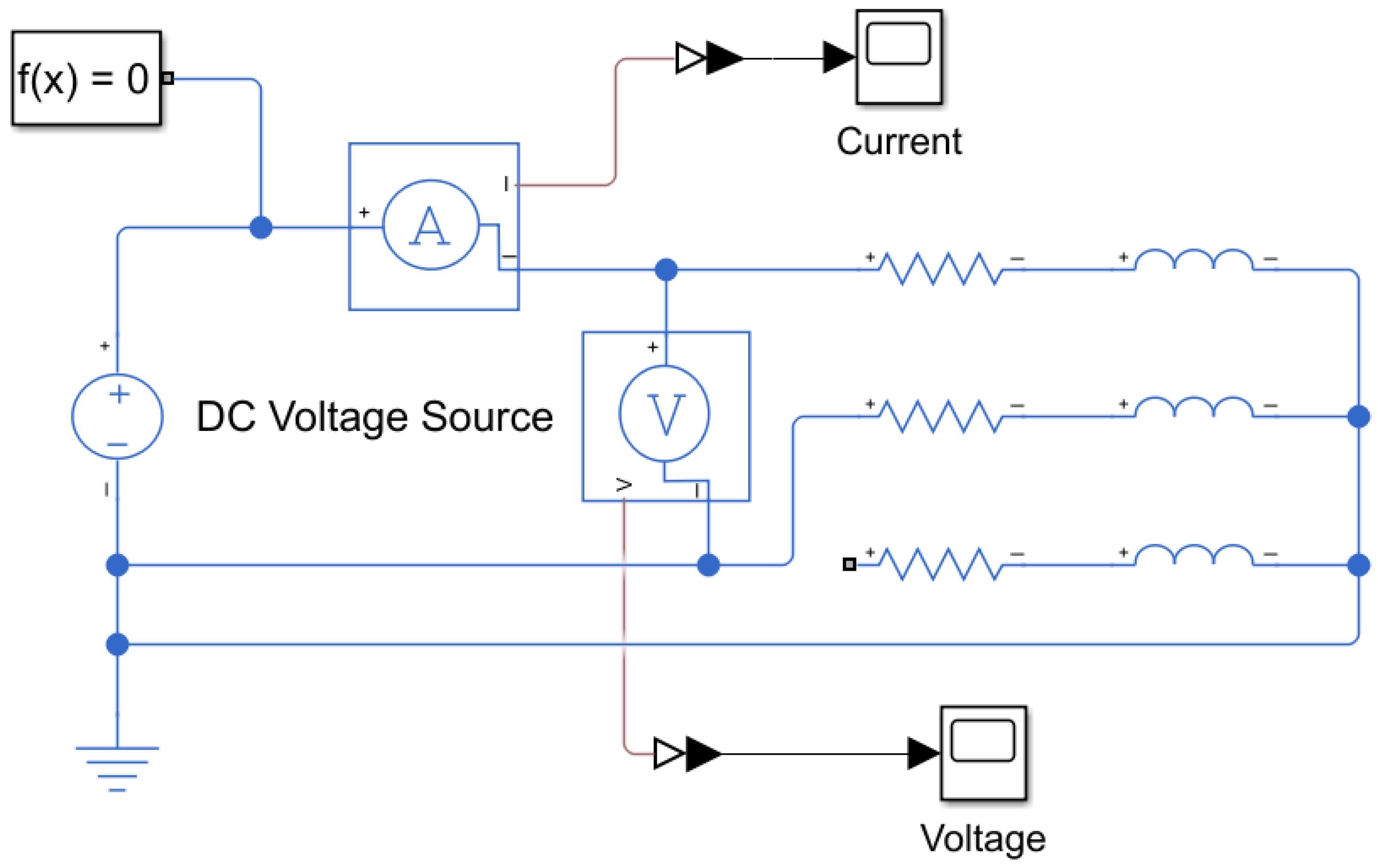
Phase resistance was measured by applying a variable DC voltage into two BLDC motor terminals and the current flow through the circuit was measured in each step while blocking the rotor, as shown in
Figure 3.
The measured and computed parameters used to determine the phase resistance of the BLDC motor are summarized in
Table 2.
To obtain an accurate measurement of the BLDC motor’s phase resistance, the effect of temperature rise due to winding heating must be considered. Therefore, the following equation was employed to ensure a high-precision estimation of the phase resistance:
where
and
.
The fourth column in
Table 2 illustrates the accurate phase resistance in Ohms.
By taking the average of the fourth column of
Table 2, the phase resistance is the following:
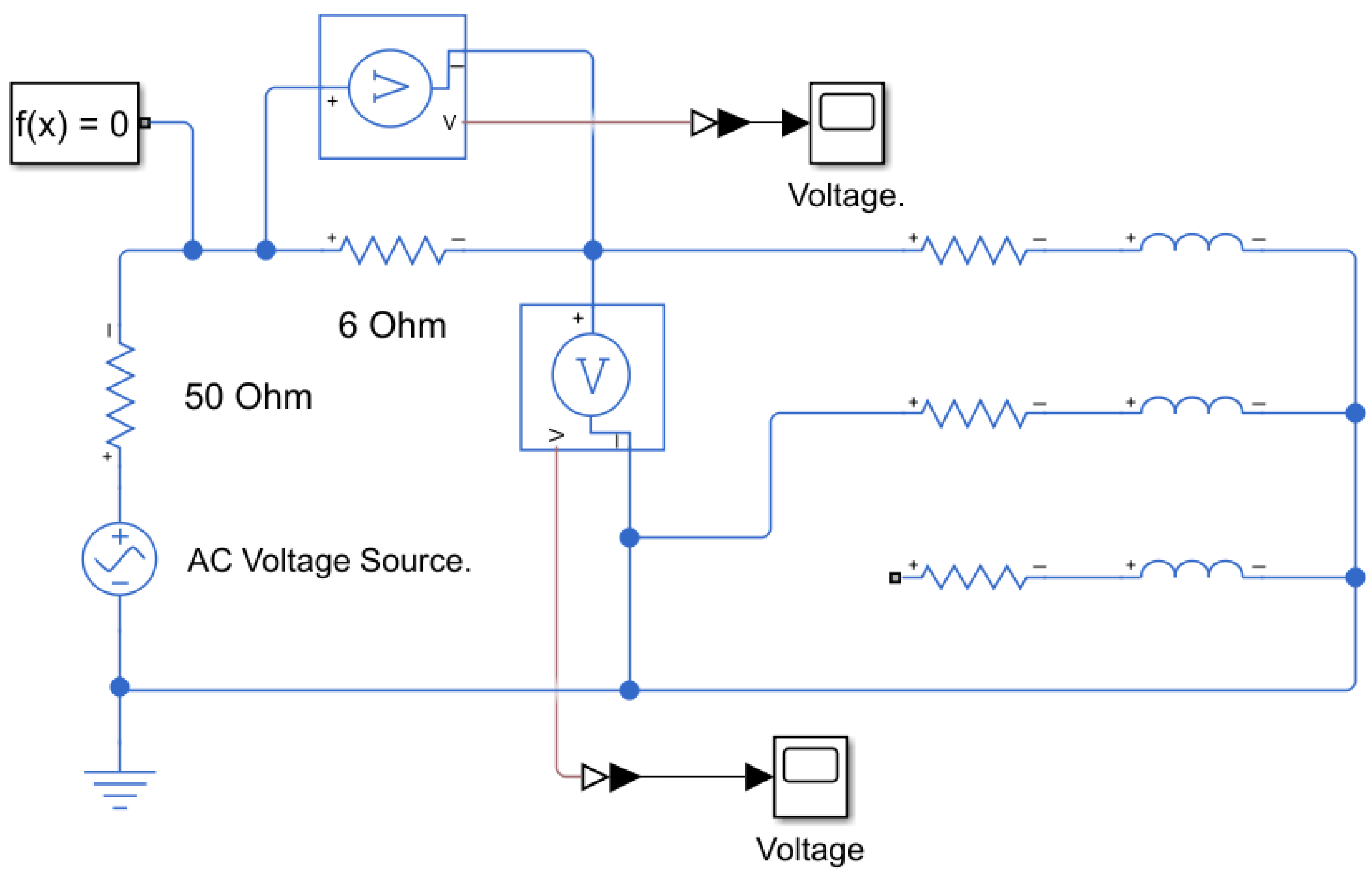
The phase inductance of the BLDC motor was experimentally measured by applying a variable AC voltage at 60 Hz across two of its terminals using a function generator with an internal resistance of 50 Ω. A 6 Ω resistor was connected in series with the motor terminals, as illustrated in
Figure 4. The voltage drop across the 6 Ω resistor was measured at each step to calculate the total current flowing through the circuit. To ensure the accuracy of the inductance measurements and eliminate the influence of back EMF, the rotor was mechanically locked during testing.
The measured and calculated values used to determine the phase inductance of the BLDC motor are summarized in
Table 3.
By taking the average of the phase inductance values presented in
Table 3, the phase inductance was determined to be the following:
The back EMF of the BLDC motor was measured by rotating the motor at a known rotational speed using an AVL dynamometer, while recording the corresponding line voltage. Based on this measurement, the back EMF constant was estimated using Equation (10).
The RMS line voltage of the BLDC motor was measured experimentally by using a digital multimeter at a rotational speed
, and it was
. Thus, the phase voltage was calculated by Equation (17), as follows:
The open-circuit voltage (
) was computed using Equation (18), as follows:
The number of pole pairs of the BLDC motor was measured by following the same procedure described previously, the electric frequency was measured at constant rotational speed. Thus, at
, the electric frequency was
, the number of poles of the BLDC motor was computed as follows:
Therefore, the number of pole pairs was the following:
The angular velocity in rad/s was the following:
Finally, the back electromotive force constant of the BLDC motor was the following:
The deceleration method was employed to estimate the moment of inertia of the BLDC motor. The motor was initially operated at various steady-state speeds and then allowed to decelerate under a constant load torque of 2.2 N.m applied by the AVL dynamometer. The angular deceleration was calculated during the coast-down phase. The total system inertia was determined using Equation (12). The inertia of the BLDC motor was then obtained by subtracting the known inertia of the dynamometer from the total inertia.
Table 4 presents the moment of inertia measurements of the BLDC motor obtained using this method.
By taking the average of the inertia column in
Table 4, the inertia of the BLDC motor is as follows:
In this study, the damping coefficient of the BLDC motor was neglected due to its minimal friction, which has an insignificant effect on the model accuracy. The estimated parameters were subsequently utilized to construct the transfer function of the BLDC motor as follows:
To assess the system’s stability, the poles of the transfer function were determined by solving the characteristic equation obtained from the denominator, as follows:
Using numerical root-finding methods, the poles were calculated as follows:
Since both poles of the identified transfer function are real and located in the left half of the complex s-plane, the system exhibits asymptotic stability. This implies that the BLDC motor’s speed response to step or continuous voltage inputs will remain bounded and converge to a steady-state value without exhibiting instability, sustained oscillations, or divergent behavior. The absence of imaginary components further indicates an overdamped response, which contributes to smooth and predictable speed transitions with minimal oscillatory effects. Such dynamic characteristics are essential for ensuring accurate speed regulation, especially under real-time operating conditions. Consequently, the identified model provides a reliable representation of the motor’s dynamic behavior, making it well-suited for the design and implementation of robust control strategies in practical applications.
The identified BLDC motor model was implemented in MATLAB/Simulink and evaluated under various input signals, as illustrated in
Figure 5. To validate the model, the same input signals were applied in real time using an experimental setup comprising the BLDC motor, Kelly controller, NI USB-6009 DAQ device, and a Li-ion battery. This setup enabled direct comparison between simulated and experimental speed responses, ensuring consistency and accuracy in model validation.
4.2. Input Signal Comparison
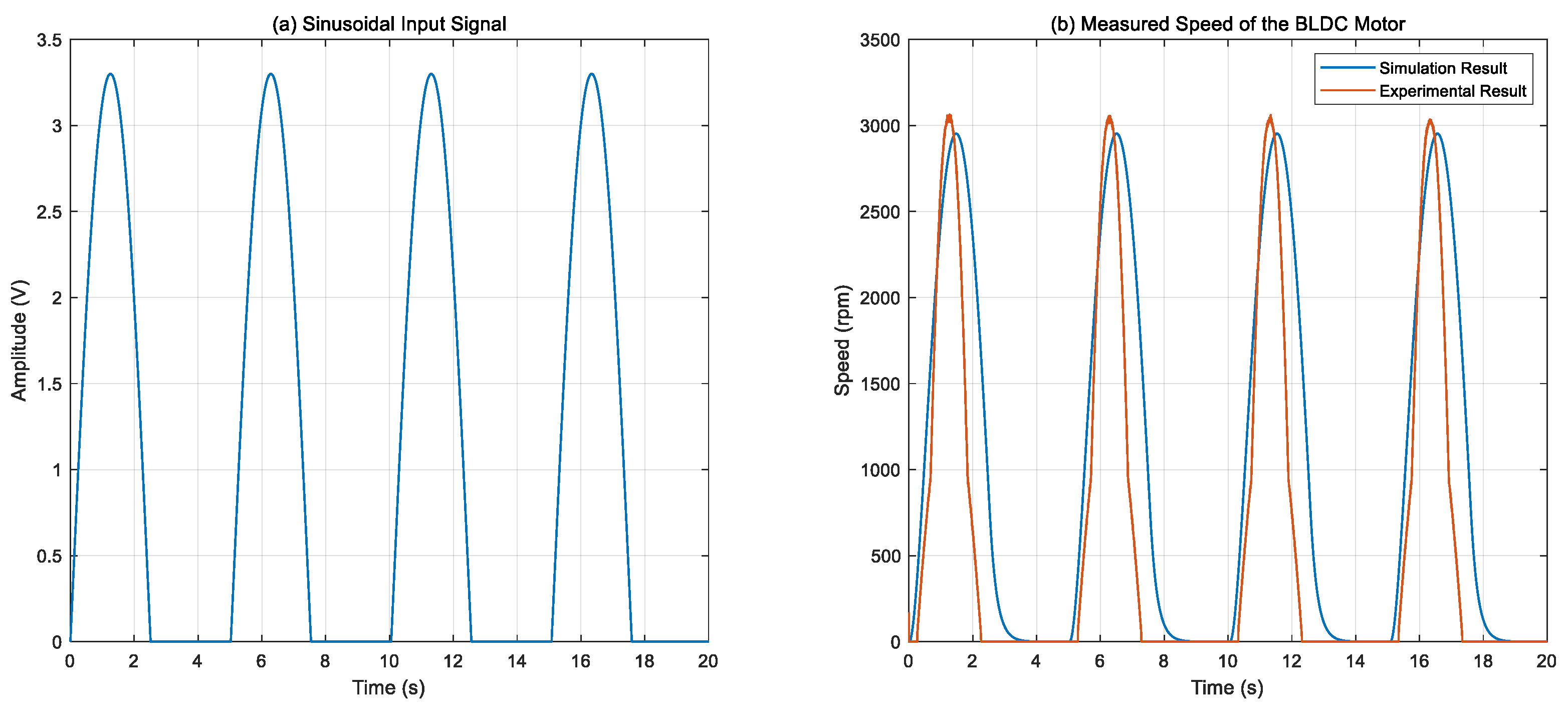
Figure 6 presents the comparison between the simulated and experimental speed responses of the BLDC motor when subjected to a sinusoidal input signal. As illustrated in
Figure 6b, both responses follow the sinusoidal input pattern over time; however, the experimental result shows a consistent phase lag and slightly slower rise and fall times compared to the simulation. These differences are mainly attributed to real-time factors such as mechanical friction, sensor latency, and dead-zone effects in the motor driver, which are not fully captured in the simulation model. Despite these discrepancies, the peak speed values and overall waveform shapes are closely aligned, demonstrating the model’s ability to accurately capture the motor’s dynamic behavior under time-varying input conditions.
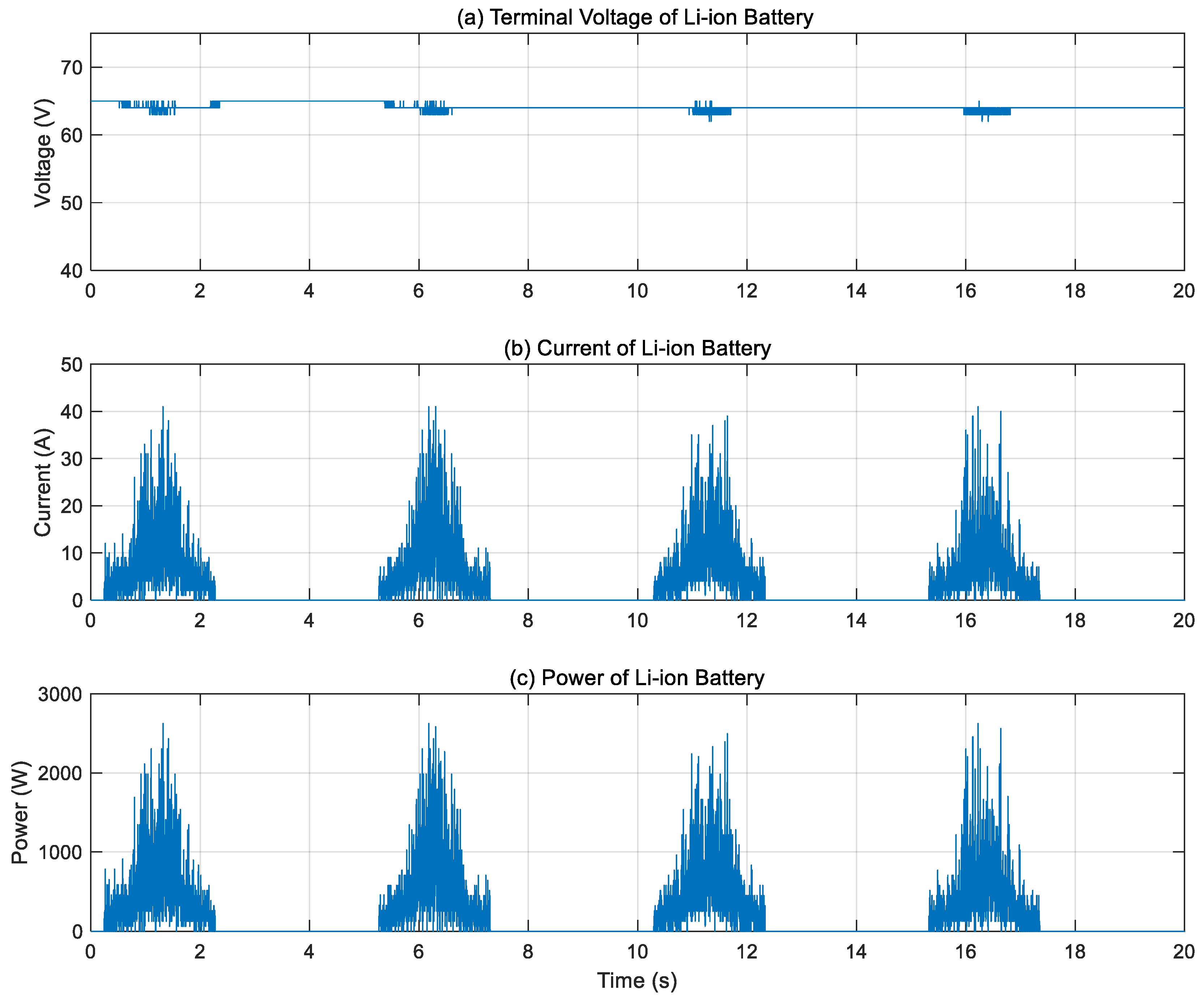
Figure 7 illustrates the dynamic performance of the Li-ion battery in terms of terminal voltage, current, and instantaneous power. As depicted in
Figure 7a, the terminal voltage remains relatively stable at approximately 64 V throughout the experiment, indicating a consistent power supply. In contrast,
Figure 7b shows significant current fluctuations ranging from 0 A to nearly 40 A. These current variations correspond to changes in motor speed in response to the applied time-varying input signals used for model validation.
Figure 7c presents the instantaneous power profile of the battery, computed as the product of the terminal voltage and current at each time instant. These results reflect the battery’s ability to respond dynamically and supply adequate power under varying operating conditions during open-loop testing.
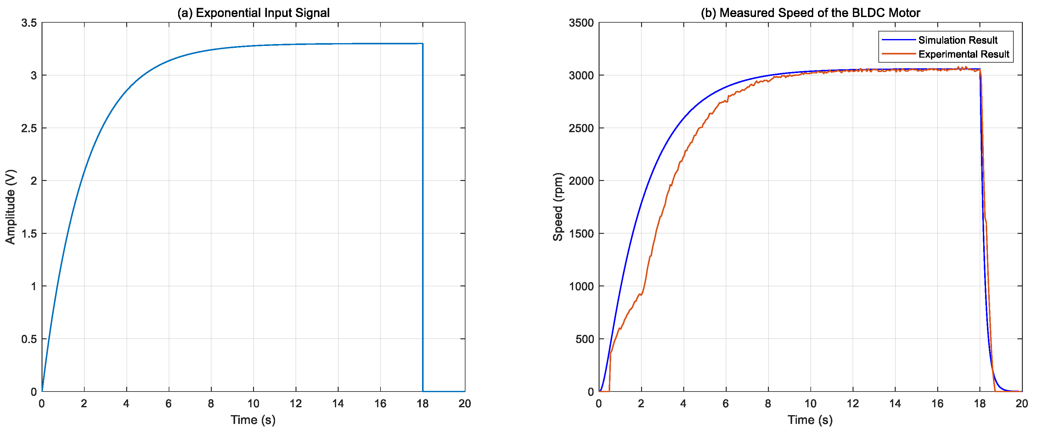
Figure 8 presents a comparison between the simulated and experimental speed responses of the BLDC motor under an exponential input signal. As shown in
Figure 8b, the simulation results demonstrate strong agreement with the experimental measurements, indicating the accuracy of the identified BLDC motor model. A slight phase lag is observed in the experimental response relative to the simulation, which can be attributed to real-time system dynamics such as mechanical friction, sensor latency, and inherent dead-zone effects in the motor driver. Despite these minor discrepancies, the overall transient and steady-state behaviors confirm the reliability of the model under dynamic input conditions.
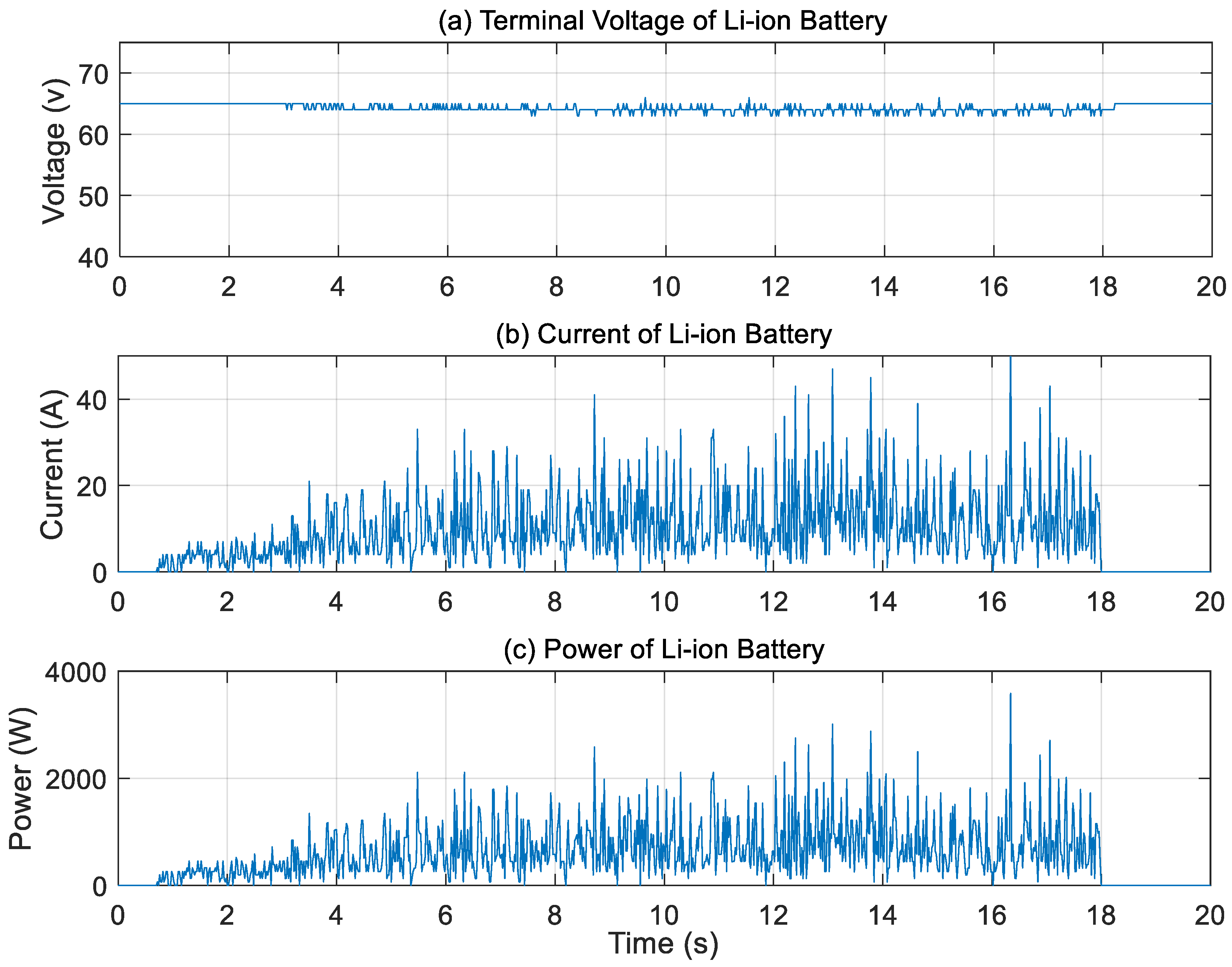
The Li-ion battery performance with respect to terminal voltage, current, and power is illustrated in
Figure 9. It is clear from
Figure 9a that the terminal voltage of the Li-ion battery is stable at approximately 64 V while the current fluctuates between 5 and 40 A, as shown in
Figure 9b, this current signal shows significant fluctuations along with a high magnitude during motor acceleration. Although no external load was applied and no feedback controller was used, the motor still draws increased current to overcome its own inertia during startup. In this open-loop configuration, an exponentially increasing voltage signal (0 to 3.3 V) was applied to the motor through the Kelly controller. The fluctuations in the current signal are primarily attributed to the PWM-based operation of the controller, which introduces high-frequency switching ripples. In addition, the BLDC motor’s inherent commutation events cause abrupt changes in current, especially at low speeds. Sensor noise and limited filtering in the data acquisition system may also amplify these variations. These combined factors explain the observed current signal fluctuations under the given test conditions.
Overall, under the exponential input, the BLDC motor exhibited a smooth and consistent acceleration profile in both the simulation and experimental tests, supporting the validity of the derived transfer function model. In the case of the sinusoidal input, the results demonstrated the motor’s ability to track a time-varying reference. While minor discrepancies in amplitude and phase were observed in the experimental response, likely due to non-ideal hardware effects such as control signal delays introduced by the Kelly controller, the simulation accurately reproduced the overall dynamic behavior. These findings confirm the effectiveness of the identified model in capturing the BLDC motor’s response under varying input conditions.
4.3. Speed Regulation of a BLDC Motor Using Closed-Loop Control
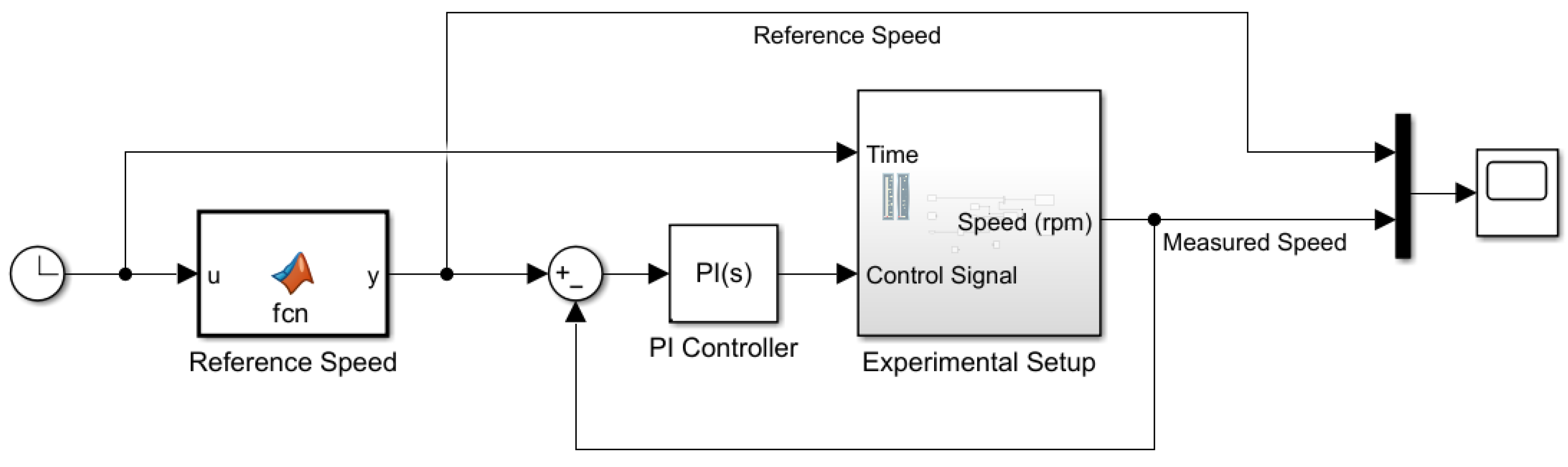
To regulate the speed of the BLDC motor, a conventional PI controller was experimentally implemented using MATLAB/Simulink, interfaced with the NI USB-6009 DAQ module and the Kelly motor controller. The control model developed in Simulink enabled real-time speed regulation by generating appropriate control signals based on the reference input. The implementation setup for BLDC motor speed control using MATLAB/Simulink is illustrated in
Figure 10.
First, a fixed reference speed of 1000 rpm was applied to evaluate the performance of the BLDC motor control system using a conventional closed-loop PI controller. The PI controller parameters were tuned using a trial-and-error approach to achieve satisfactory transient and steady-state performance. The controller was implemented in MATLAB/Simulink and integrated with the real-time hardware setup to facilitate both control execution and system monitoring.
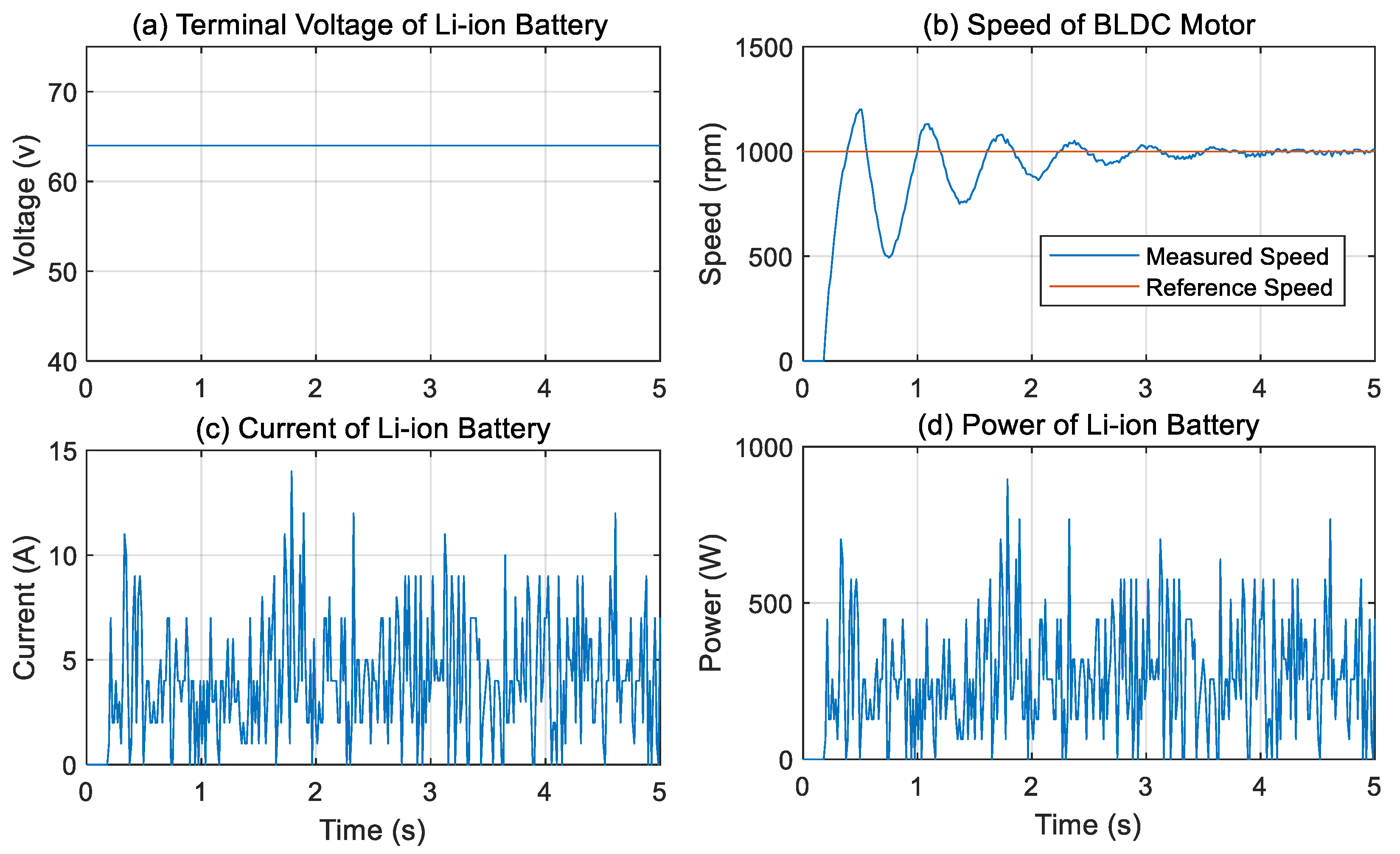
Figure 11 shows the experimental results of the BLDC motor and Li-ion battery.
Figure 11b presents the measured speed response of the BLDC motor in comparison with the reference speed profile. The motor reaches 1000 rpm at approximately 0.3 s, exhibiting a pronounced overshoot indicative of an underdamped response. This behavior is primarily attributed to sensor noise and inherent system nonlinearities. Moreover, the speed stabilizes after around 3 s and closely follows the reference signal, reflecting a minimal steady-state error. The controller demonstrates effective performance in correcting deviations and maintaining a stable operating point. Additionally, the terminal voltage and current of the Li-ion battery, extracted from the Kelly controller using a Python 3.12-based data acquisition script, are depicted in
Figure 11a and 11c, respectively.
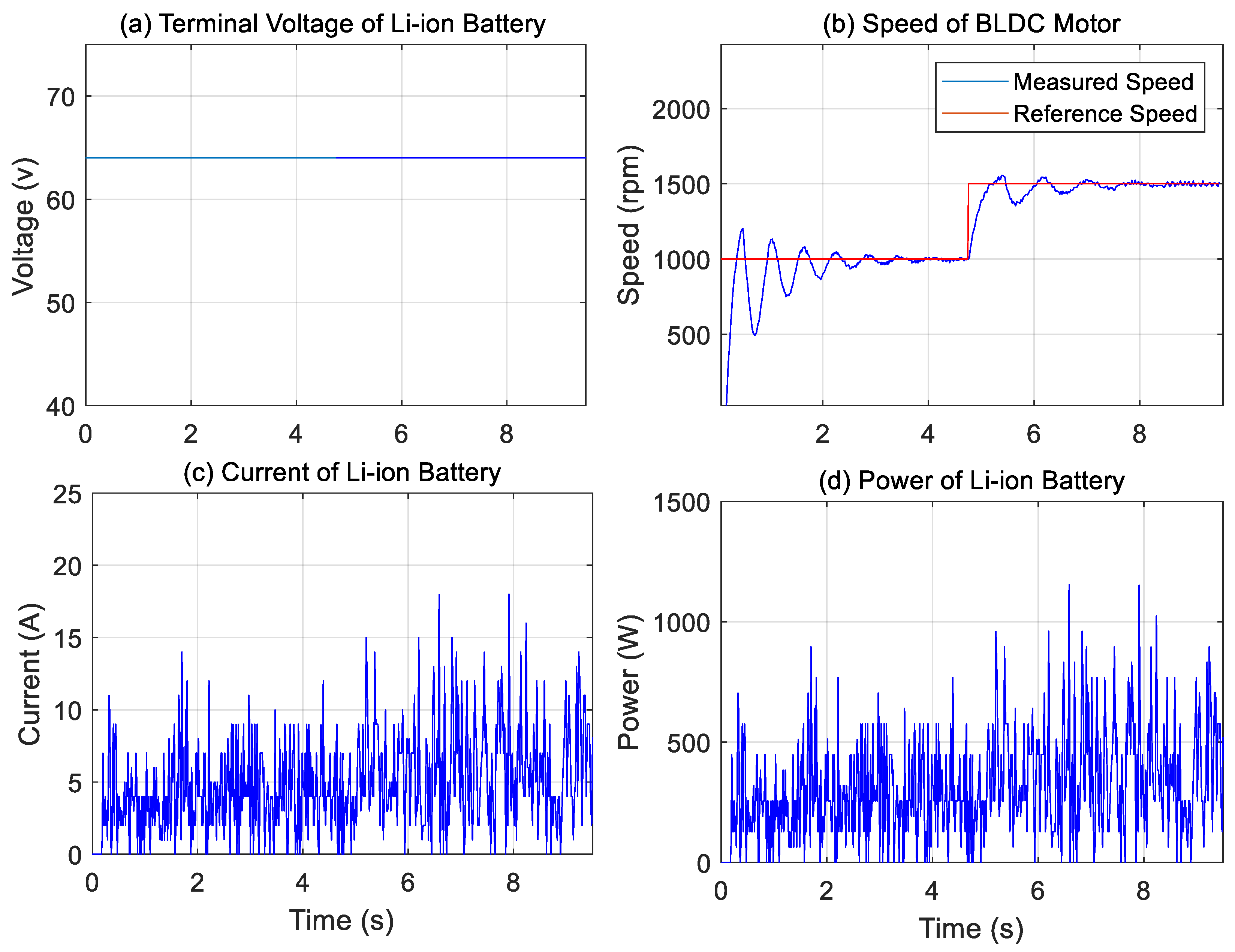
Second, two variable speed setpoints, 1000 rpm and 1500 rpm, were applied during this test using a conventional PI controller to evaluate the performance of the BLDC motor control system.
Figure 12b shows the measured speed response in comparison with the reference speed. The motor successfully tracks the reference with minor fluctuations, which are primarily attributed to sensor noise and system nonlinearities. The controller demonstrates effective performance in minimizing these deviations, thereby maintaining a stable operating point. Furthermore, a noticeable time delay is observed in the system response, as shown in
Figure 11b and
Figure 12b, with estimated values of approximately 0.2 s and 0.1 s, respectively. This delay is likely caused by sensor latency or the controller’s processing time.
On the other hand, the terminal voltage of the Li-ion battery, as illustrated in
Figure 11a and
Figure 12a, remains relatively stable throughout the experiment, fluctuating between 62 V and 64 V. This voltage stability indicates that the battery operated within its regulated limits, and the applied motor load did not result in significant voltage drops. These observations confirm the battery’s sufficient capacity and reliable power delivery capability during the testing conditions.
In contrast, the current profiles shown in
Figure 11c and
Figure 12c exhibit noticeable fluctuations, with values generally ranging between 5 A and 15 A. These variations correspond to changes in motor speed, particularly during acceleration phases, where increased current demand is expected. The observed fluctuations may also be partially attributed to sensor inaccuracies and the nonlinear behavior of the overall system. Furthermore,
Figure 11d and
Figure 12d present the instantaneous power of the Li-ion battery, calculated as the product of the terminal voltage and current at each time instant.
In the first and second experiments, a conventional PI controller was employed to regulate the BLDC motor speed. However, the system exhibited noticeable overshoot and response delay, indicating the need for improved control performance. To address these issues, a first-order LPF was integrated into the control loop during the third experiment. The filter, used in conjunction with the PI controller, effectively attenuated high-frequency components in the control signal and enhanced the overall robustness of the system. As a result, significant improvements were observed in transient response characteristics, including reduced rise time, faster settling time, and lower steady-state error.
The first-order transfer function of the LPF employed in this study is given by the following equation:
The time constant of the first-order LPF was tuned iteratively until the control signal exhibited satisfactory dynamic performance.
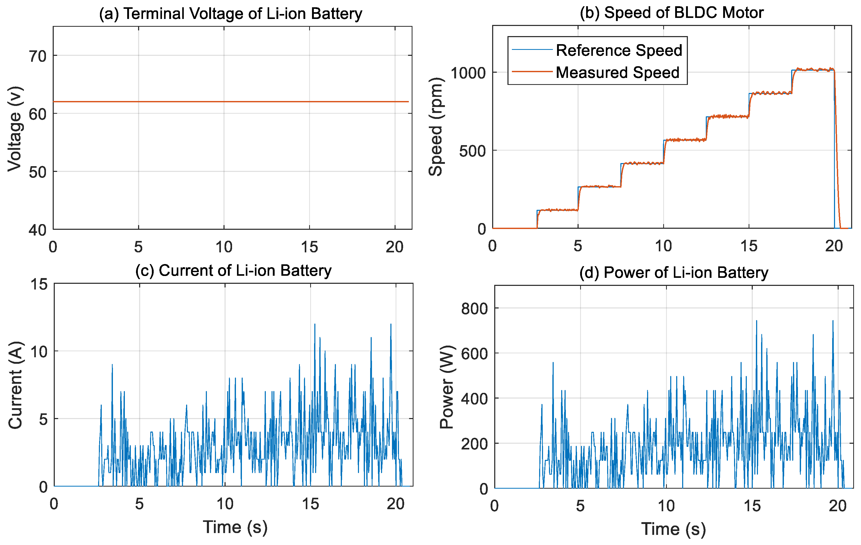
As shown in
Figure 13a, the terminal voltage of the Li-ion battery remains stable at approximately 62.5 V throughout the test, indicating reliable voltage regulation, while
Figure 13b presents both the reference and measured speeds of the BLDC motor. The measured speed closely follows the reference speed, demonstrating that the control system is well-tuned with minimal steady-state error.
Furthermore, the motor responds promptly to changes in reference input, reaching the desired speed within a short time without significant delay. No sustained oscillations or instability are observed, confirming that the system exhibits predictable and stable dynamic behavior.
Figure 13c illustrates the current profile of the Li-ion battery, where fluctuations are evident. These current variations correspond to motor acceleration phases, during which higher current is drawn. Some signal noise may also be attributed to sensor inaccuracies and nonlinearities within the system. Overall, the system demonstrates reliable performance with good tracking accuracy, fast dynamic response, and operational stability. Additionally,
Figure 13d illustrates the instantaneous power of the Li-ion battery. This power is calculated as the product of the terminal voltage and current at each time instant.
Figure 14 shows the behavior of the control signal in the BLDC motor control system before and after applying an LPF. Unfiltered control signal exhibits sharp high-frequency spikes and ripples, which are typical in control systems due to switching noise or sensor jitter. In contrast, the filtered control signal was significantly smoother and cleaner.
Overall, applying an LPF significantly improves control signal smoothness by removing undesirable high-frequency components while preserving the general control trend. This is crucial in practical motor control applications for ensuring smooth operation and protecting hardware.
5. Conclusions
In this study, a comprehensive experimental approach was employed to identify the electrical, mechanical, and electromagnetic parameters of a BLDC motor. Resistance and inductance were determined through DC and AC measurements, respectively, while the back EMF constant and moment of inertia were estimated using an AVL dynamometer. The back EMF constant was calculated by operating the motor in generator mode and measuring the open-circuit voltage at varying speeds. In contrast, the moment of inertia was derived using a deceleration-based method by analyzing the motor’s angular velocity decline after power cutoff.
Furthermore, the identified parameters were used to construct a transfer function model that accurately captures the dynamic behavior of the BLDC motor under no-load conditions. This model was implemented in MATLAB/Simulink and validated through real-time experimental testing using sinusoidal and exponential input signals. The close agreement between simulated and measured responses confirmed the validity and reliability of the identified model.
Moreover, a PI controller was developed for speed regulation and implemented using a cost-effective and accessible hardware setup comprising the NI USB-6009 data acquisition device and a Kelly controller. A first-order LPF was incorporated into the control loop to attenuate high-frequency noise and improve the transient response of the system. Experimental tests using a stepwise reference speed profile demonstrated precise speed tracking, reduced overshoot, and enhanced system stability under various operating conditions.
Finally, while the modeling and control techniques applied in this study are based on established methods, the novelty of the work lies in the integration of experimental parameter identification, model validation, and real-time control within a unified and practical framework. This replicable methodology provides a valuable foundation for future research and development in motor control systems, especially in contexts where high-end laboratory infrastructure may not be available. In future work, this framework may be extended to include advanced control strategies such as model predictive control, adaptive control, or data-driven methods. Additionally, incorporating real-time load variations and evaluating system performance under more dynamic operating scenarios would further enhance the robustness and applicability of the proposed system.


