1. Introduction
With the evolution of modern industrial technology toward lightweight and high-efficiency paradigms, lubrication technologies for transmission systems are undergoing fundamental reconfiguration and innovation. As a core unit of vehicle powertrains, gear reducers occupy a pivotal position in automotive transmission systems due to their compact structural design and high-efficiency power output. Comprising a functionally coupled assembly of precision components such as meshing pairs and bearing systems, the interfacial tribological performance and energy transfer efficiency of these devices directly govern vehicle energy consumption levels and operational reliability. Against this backdrop, reducing power losses through optimized transmission structural parameters and lubrication control mechanisms has become a critical pathway for enhancing the energy efficiency ratio and service lifespan of gear reducers. Studies have shown that hydrodynamic resistance effects induced by gear rotation in lubricating oil can lead to oil churning power losses accounting for 18–35% of the total transmission system energy consumption, a phenomenon particularly pronounced under high-speed, low-load operating conditions [
1,
2,
3]. Traditional splash lubrication relies on centrifugal forces generated by gear rotation to achieve oil self-circulation, requiring lubricants to simultaneously meet multiple demands under extreme operating conditions: maintaining Newtonian fluid characteristics at −40 °C, preserving oxidation stability at 150 °C, and achieving oil film load-bearing capacity across a wide temperature range through precise viscosity–temperature regulation [
4,
5,
6]. Therefore, investigating the mechanistic impacts of critical parameters, such as gear speed and oil immersion depth, on churning losses, and establishing quantitative correlation models between lubrication performance and energy dissipation characteristics, hold significant engineering value for advancing the design and performance optimization of gear transmission systems.
During the operation of gear reduction boxes, the rotational motion of gear mechanisms induces a splash effect in the lubricating oil. Through specially designed diversion structures within the housing, splashed oil droplets are effectively directed to wall-mounted oil collection grooves. The lubricant is then transported through dedicated oil passages to bearing lubrication zones before ultimately returning to the oil reservoir, thereby forming a complete lubrication circulation loop. The integrity of this circulatory system constitutes a critical factor in ensuring equipment lubrication safety: insufficient oil film formation in bearing areas may lead to abnormal temperature rises, aggravated vibration, and excessive noise, while lubrication failure at gear meshing interfaces can result in mechanical damage, such as adhesive wear. When the gear linear velocity increases, dynamic airflow generated by rotating components creates an air barrier effect. This gas–liquid coupling interaction impedes normal lubricant delivery to meshing zones, causing uneven oil film distribution and localized oil starvation phenomena. To achieve precise oil supply for internal components in gearboxes, it is essential to comprehensively understand the flow characteristics of lubricants within oil passages and the influence of various parameters on lubrication performance [
7,
8,
9]. Concurrently, under the premise of ensuring operational safety and reliability, structural optimizations, including adjustment of oil passage orientation angles, modification of groove dimensions, and optimization of orifice parameters, should be implemented to enhance overall lubrication effectiveness.
It is evident that the core constraints on gearbox system performance, durability, and service life fundamentally originate from the multiphase flow-coupling mechanisms and associated thermodynamic effects within its complex internal flow field environment. The dynamic interactions of this oil–gas multiphase medium not only directly influence lubrication efficiency and heat dissipation characteristics, but also significantly constrain the energy transmission efficiency of the drive system through boundary layer friction and hydraulic losses. Consequently, the establishment of engineering-predictive multiphysics coupling models during the design phase for the quantitative evaluation and optimization of lubrication cooling system performance has emerged as a critical technological breakthrough in modern gearbox design. Through CFD simulations, we can accurately reconstruct complex flow phenomena in gear meshing zones, including oil splashing, gas–liquid mixing, and turbulent dissipation, thereby obtaining three-dimensional spatiotemporal evolution characteristics of critical parameters such as lubricant film distribution and temperature gradient fields during early design stages. This flow field visualization-based reverse design approach not only provides data support for optimizing geometric parameters like the gear immersion depth and housing flow-guiding structures, but also enables innovative topology optimization of lubrication channels. By implementing parametric simulation models for multi-condition iterative calculations, the systematic reduction of churning losses and improvement of thermal equilibrium can be achieved while maintaining adequate tooth-surface lubrication, realizing the optimization objective of “efficiency enhancement with reduced consumption” in lubrication systems. This design paradigm, integrating fluid dynamics simulation with structural optimization, ultimately drives gear transmission systems toward advanced manufacturing directions characterized by low energy consumption, high reliability, and extended service life, providing technical assurance for the improvement of industrial equipment energy efficiency and sustainable development.
As the core component of mechanical transmission systems, the study of internal lubrication mechanisms in gearboxes has always presented unique challenges. Due to their sealed design and highly complex internal structures (containing meshing gear pairs, bearing assemblies, and multi-stage transmission components), researchers face difficulties in directly observing the dynamic distribution characteristics of lubricating oil during high-speed operation through conventional experimental methods. With advancements in computational power and numerical analysis techniques, CFD technology has emerged as a pivotal tool for investigating splash lubrication mechanisms in gearboxes. By establishing three-dimensional numerical models, this technology not only accurately simulates complex physical phenomena, such as oil splashing and gas–liquid mixing during gear engagement, but also significantly reduces experimental costs, providing crucial theoretical support for optimizing the design of gearbox lubrication systems [
10,
11,
12,
13]. Regarding specific applications of CFD technology, scholars have achieved a series of innovative breakthroughs. Shen et al. [
14] investigated churning power loss in meshing gear pairs under no-load conditions, systematically examining the effects of gear rotational speed, transmission ratio parameters, and tooth profile characteristics on churning loss. Hildebrand et al. [
15] conducted numerical analysis on heat transfer between gears and fluids, revealing that localized interactions, oil wettability, and circumferential velocity significantly influence heat transfer coefficients. Their work demonstrated that combining a “splash model” with numerical simulations of fluid flow characteristics could effectively enhance heat transfer prediction accuracy. Zhang et al. [
16] explored the injection angle, distance, and velocity in high-speed gearboxes under negative pressure, with the results indicating that appropriate negative pressure improves lubrication effectiveness, while closer injection distances and higher injection velocities yield superior lubrication performance. Lu et al. [
17] achieved coupled simulation of gear rotational motion and fluid dynamic responses by integrating the Multiple Reference Frame (MRF) method with an Eulerian multiphase flow model. By introducing turbulence correction factors to improve the convective heat transfer model, they obtained the temperature distributions of oil–gas two-phase flow under varying rotational speeds. Keller et al. [
18,
19] evaluated the influence of the injection velocity, angle, diameter, and volume on gearbox spray lubrication performance, using the maximum oil immersion area and lubricant spreading velocity on gear end faces as evaluation criteria. Hu et al. [
20,
21,
22,
23] investigated the splash lubrication characteristics of helicopter spiral bevel gearboxes under dynamic flight conditions, systematically analyzing the effects of oil immersion depth, rotational speed, oil temperature, and fuselage tilt angle on lubricant distribution. Their work revealed that dynamic gearbox motion deteriorates lubrication performance in meshing zones by suppressing oil pumping effects. Peng et al. [
24] established a three-dimensional simulation platform for gear lubrication systems using the VOF two-phase flow model, successfully capturing the microscopic spreading process of lubricant in tooth contact regions. Most scholars have focused on analyzing splash lubrication flow field distributions and churning loss in gearboxes, with limited research targeting small-scale engineering applications involving simple geometric configurations. These studies collectively demonstrate the broad applicability and high accuracy of CFD methods in gearbox splash lubrication analysis.
Despite significant advancements in CFD for gear lubrication, its application still faces multiple challenges: (1) Computational Complexity: The intricate geometric structure of gearboxes necessitates large-scale meshing, leading to poor transient solution convergence and substantial consumption of computational resources. (2) Modeling Limitations: The lack of precise models for the non-Newtonian behavior of lubricants and multi-field coupling mechanisms involving gas–liquid interfacial tension results in a disconnect between predictions of microscopic hydrodynamic pressure generation and macroscopic lubrication failure. (3) Transient Dynamics: Existing studies predominantly rely on steady-state assumptions, failing to characterize transient phenomena such as oil film oscillations and transport hysteresis induced by inertial forces. To address these challenges, this study establishes a three-dimensional dynamic multiphase flow simulation model based on CFD technology to systematically analyze the interaction mechanisms between turbulent flow fields and lubricant films under high-speed gear rotation. Special emphasis is placed on quantifying the influence of the oil injection distance on lubricant transport characteristics. The analytical results provide a quantitative evaluation methodology for the low-power consumption design of lubrication structures in high-speed transmission systems. Notably, engineering-oriented improvements for oil mist suppression and thermal management optimization are proposed, offering critical insights for enhancing gearbox transmission efficiency and operational reliability.
Aiming to enhance the lubrication performance and energy efficiency of high-speed gear reducers, this study developed a three-dimensional dynamic simulation model based on CFD. Utilizing the VOF two-phase flow model and the standard k-ε turbulence model, the research systematically investigated the influence of oil injection distance on oil film distribution, vortex viscosity, and turbulent kinetic energy within gear meshing zones. Numerical simulations revealed the transport characteristics of lubricating oil under centrifugal and shear forces. By overcoming the limitations of conventional steady-state analyses, the study establishes a dynamic correlation model between injection parameters and flow field properties, providing a theoretical foundation for low-power lubrication design and thermal management strategies in gearboxes. These findings hold significant engineering value for achieving energy savings and reliability improvements in transmission systems.
4. Numerical Results and Discussion
4.1. The Influence of Different Oil Injection Distances on the Oil Volume Fraction on Tooth Surfaces
In the dynamic observation of lubrication in gear transmission systems, the encapsulation morphology and dynamic evolution of lubricants in meshing zones are critical determinants of lubrication efficiency and anti-wear performance. Existing studies demonstrate that adjusting the oil injection distance to modify lubricant distribution in contact zones represents a technically simple yet effective optimization method. However, due to the coupling effects of complex interfacial hydrodynamic interactions and centrifugal force fields during gear meshing, the quantitative correlation mechanisms between oil injection distance parameters and lubrication efficacy remain insufficiently elucidated, which directly constrains the precision optimization of lubrication system parameters. To address this gap, this study dynamically captured the lubricant transport process in the
xz cross-section of meshing gears. By comparatively analyzing oil-phase distribution characteristics under varying oil injection distances, significant regulatory effects of nozzle positioning on lubricant film formation were observed, as illustrated in
Figure 4.
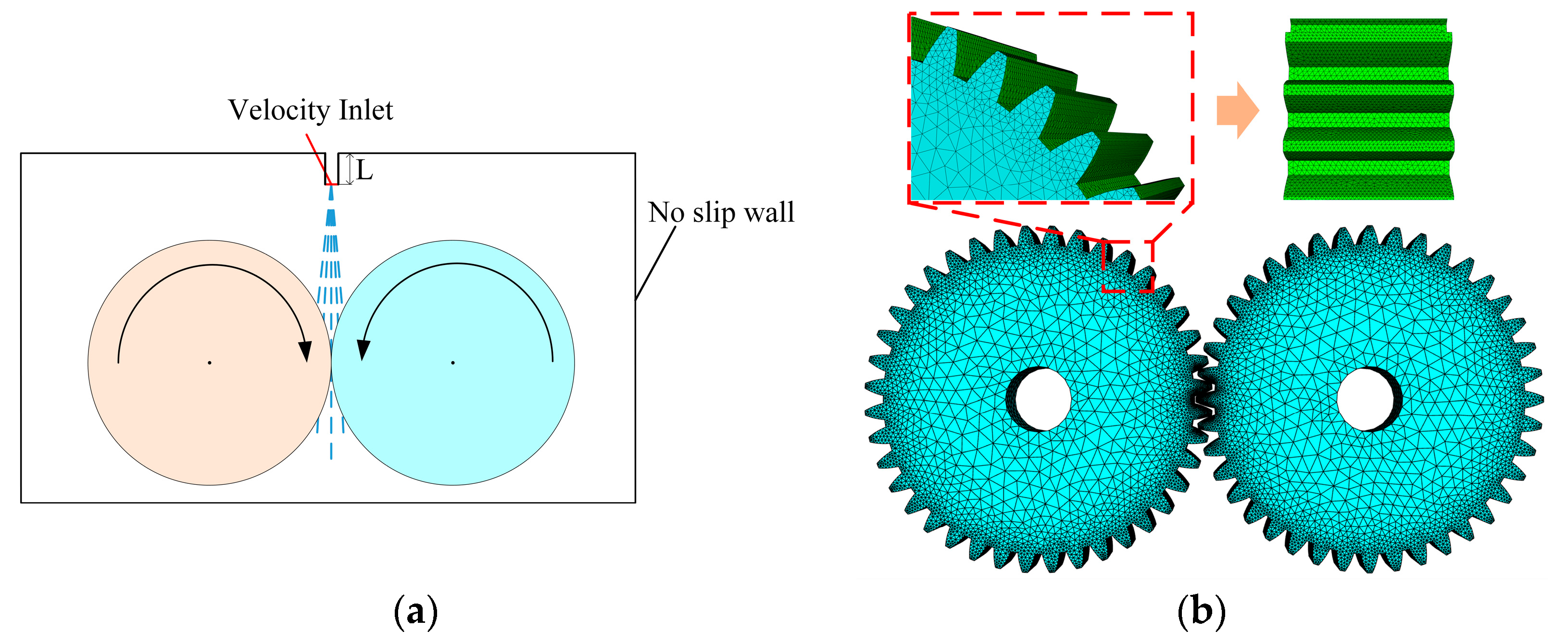
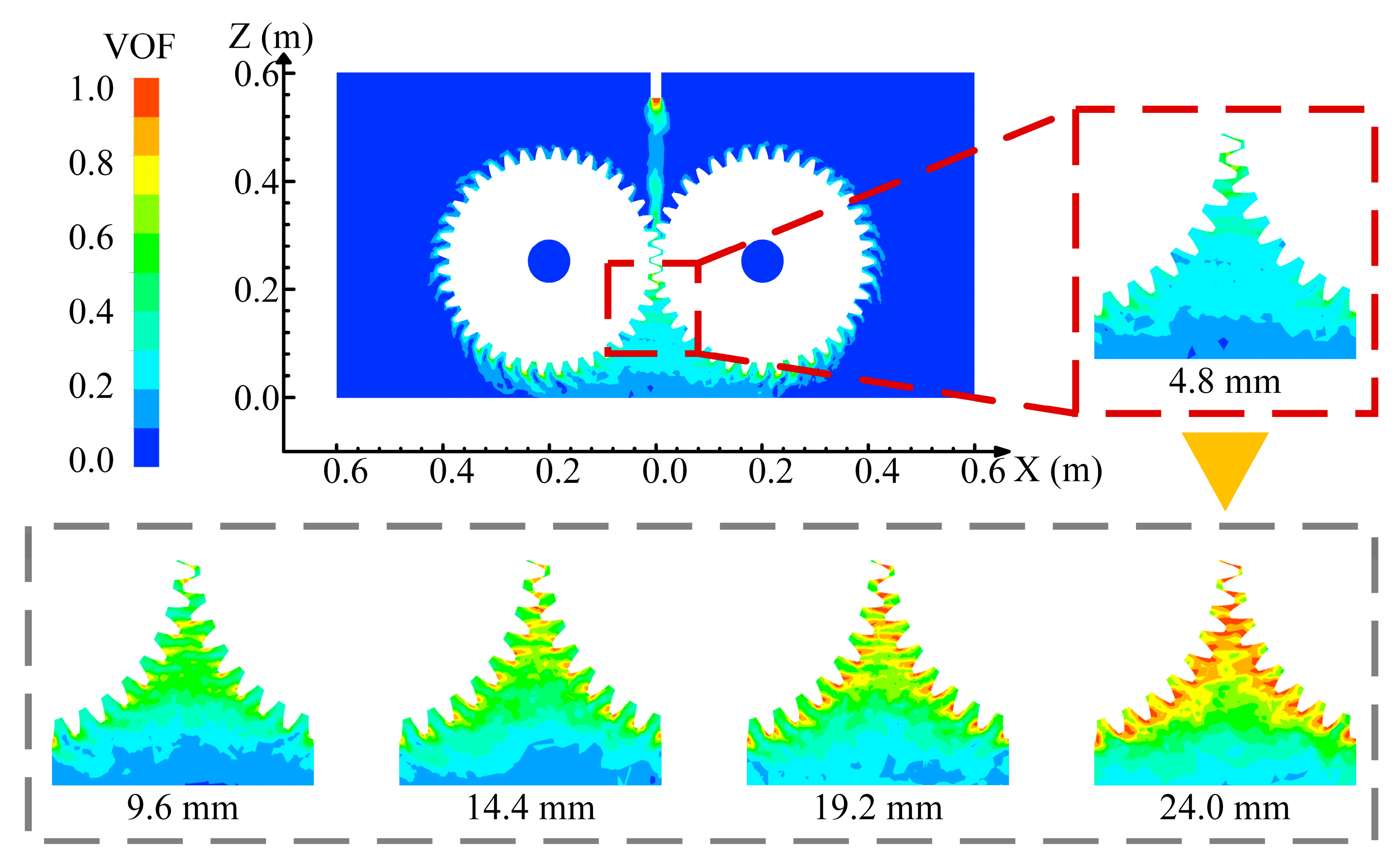
To quantitatively characterize the oil injection distance, this study adopted the vertical clearance between the nozzle outlet center and the upper wall of the gearbox as the measurement criterion. An increase in this parameter indicates that nozzle’s geometric position is approaching the gear meshing zone. Through the oil distribution nephograms in the axial section of the gearbox shown in
Figure 4, the coverage characteristics of lubricating oil in the meshing region under different injection distances can be visually observed. Under smaller injection distances (e.g., 4.8 mm), the oil distribution exhibits significant discrete characteristics: extensive low-concentration regions (represented by blue backgrounds) coexist with sporadic green high-concentration patches. This discontinuous distribution pattern is particularly pronounced in the tooth root area, revealing severe surface wetting defects. The fundamental mechanism lies in that excessive injection distance causes continuous kinetic energy attenuation of oil droplets due to air resistance, resulting in insufficient impact momentum when the oil flow reaches the meshing zone. In this state, the lubricant fails to form a complete oil film on tooth surfaces through centrifugal effects before undergoing secondary atomization at the high-speed rotating gear pair surfaces, ultimately forming discrete droplet clusters. This discontinuous medium distribution directly prevents the establishment of effective hydrodynamic lubrication between meshing surfaces, thereby exacerbating friction and wear risks in the gear system.
With a progressive reduction in the oil injection distance, the oil-phase distribution demonstrates significant structural transformations. At the 14.4 mm condition, the expansion of yellow zones indicates enhanced oil film continuity, where localized enveloping layers begin to form on tooth surfaces. When the distance decreases to 19.2 mm, closed-loop structures of red high-concentration regions emerge at the meshing entry side, signifying the establishment of stable transport channels within tooth-surface gaps. Particularly under the optimal 24 mm condition, the magnified observation area reveals distinctive peak-shaped distribution characteristics, where dense wedge-shaped oil films develop between tooth surfaces, effectively covering stress concentration zones. The underlying physical mechanism resides in near-field injection imparting higher initial kinetic energy to the oil, enabling both the gas–liquid interfacial tension to be overcome and the directional flow to be realized through tooth-surface rotation. Under the combined action of centrifugal and Coriolis forces, the oil extends along tooth profiles, fundamentally differing from the random splashing patterns observed in long-distance injection. Simultaneously, comparative analysis between main and magnified diagrams uncovers a critical principle—oil film quality depends not merely on overall coverage, but more crucially on the formation of local concentration gradients. As the injection distance shortens, high-concentration zones migrate from tooth tips toward meshing regions, creating medium-gradient distributions that are favorable for hydrodynamic lubrication.
The above results demonstrate that as the nozzle position approaches the meshing zone, enhanced droplet kinetic energy enables the oil to overcome external disturbances such as centrifugal forces and air turbulence, achieving stable retention and migration between tooth surfaces. Concurrently, elevated local oil-phase concentration facilitates the establishment and maintenance of wedge-shaped oil films, thereby realizing the transition from initial lubricant spreading to stable encapsulation.
The oil distribution characteristics and dynamic evolution processes within gear meshing zones constitute critical factors influencing the thermal management performance of gear transmission systems. Specifically, the coverage extent of lubricant and oil film formation capacity directly govern the thermal conduction efficiency in contact regions. Simultaneously, the lubrication status at tooth-surface contact interfaces significantly affects the interfacial thermodynamic behavior of friction pairs. The oil film thickness and pressure distribution not only determine contact-stress uniformity, but also decisively influence the overall thermal equilibrium of gear systems by modifying interfacial friction coefficients and heat flux density distributions. To investigate this mechanism, the present study conducted comprehensive analyses of the oil volume fraction in gear meshing zones, as illustrated in
Figure 5. This quantitative approach revealed spatial–temporal variations in lubrication media under operational conditions, providing essential insights into the coupled thermo-hydrodynamic interactions within precision gear engagements.
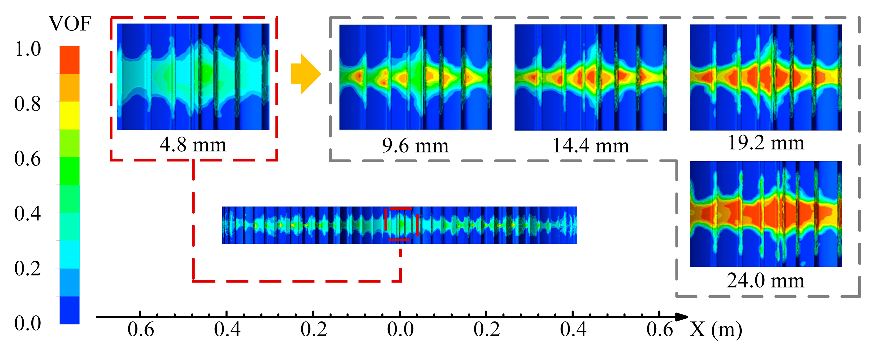
This study elucidates the spatiotemporal evolution patterns of oil distribution and thermodynamic regulation mechanisms in gear lubrication systems through visualized modeling. The oil volume fraction exhibits pronounced spatial heterogeneity along the gear axial direction: a concentration peak forms directly below the nozzle (x = 0 mm region), yet rapidly attenuates with axial distance, while displaying periodic fluctuation characteristics. This gradient distribution fundamentally reflects the dynamic interplay between centrifugal effects and viscous resistance during lubricant transport. When the oil injection distance is ≤14.4 mm, Coriolis force-dominated centrifugal separation induces oil film rupture (volume fraction fluctuation amplitude: 0.4–0.6), generating discrete lubrication islands in meshing zones. Such discontinuous coverage substantially compromises the gear’s intrinsic heat dissipation capacity.
The discrete oil distribution in gear meshing zones often leads to inadequate lubrication, which is particularly exacerbated under high-speed operation. During gear engagement, high-frequency mechanical contacts and collisions between gear pairs rapidly convert kinetic energy into thermal energy, causing localized temperature spikes. Insufficient or uneven oil coverage in these critical regions critically undermines the lubricant’s cooling and friction-reducing functions, accelerating surface wear and potentially inducing scuffing failures. Thus, ensuring sufficient and uniform oil coverage proves crucial for enhancing both lubrication efficiency and thermal management capabilities in gear systems. The findings reveal that smaller injection distances, while enabling oil delivery near gears, yield limited surface coverage due to insufficient kinetic energy. The lubricant predominantly exists as isolated droplets, resulting in low and discontinuous volume fractions that constrain lubrication effectiveness. With appropriate increase in the injection distance, the oil achieves superior momentum regulation during air-mediated transport, significantly improving distribution uniformity and coherence across tooth surfaces. This optimization elevates oil volume fractions in critical regions while establishing more continuous and stable oil films, not only enhancing lubrication performance, but also strengthening the heat dissipation capacity. The resultant improvements in thermal management effectively mitigate operational temperature rises and prolong gear service life. Consequently, rational optimization of oil injection distance proves paramount for advancing the comprehensive performance of gear transmission systems.
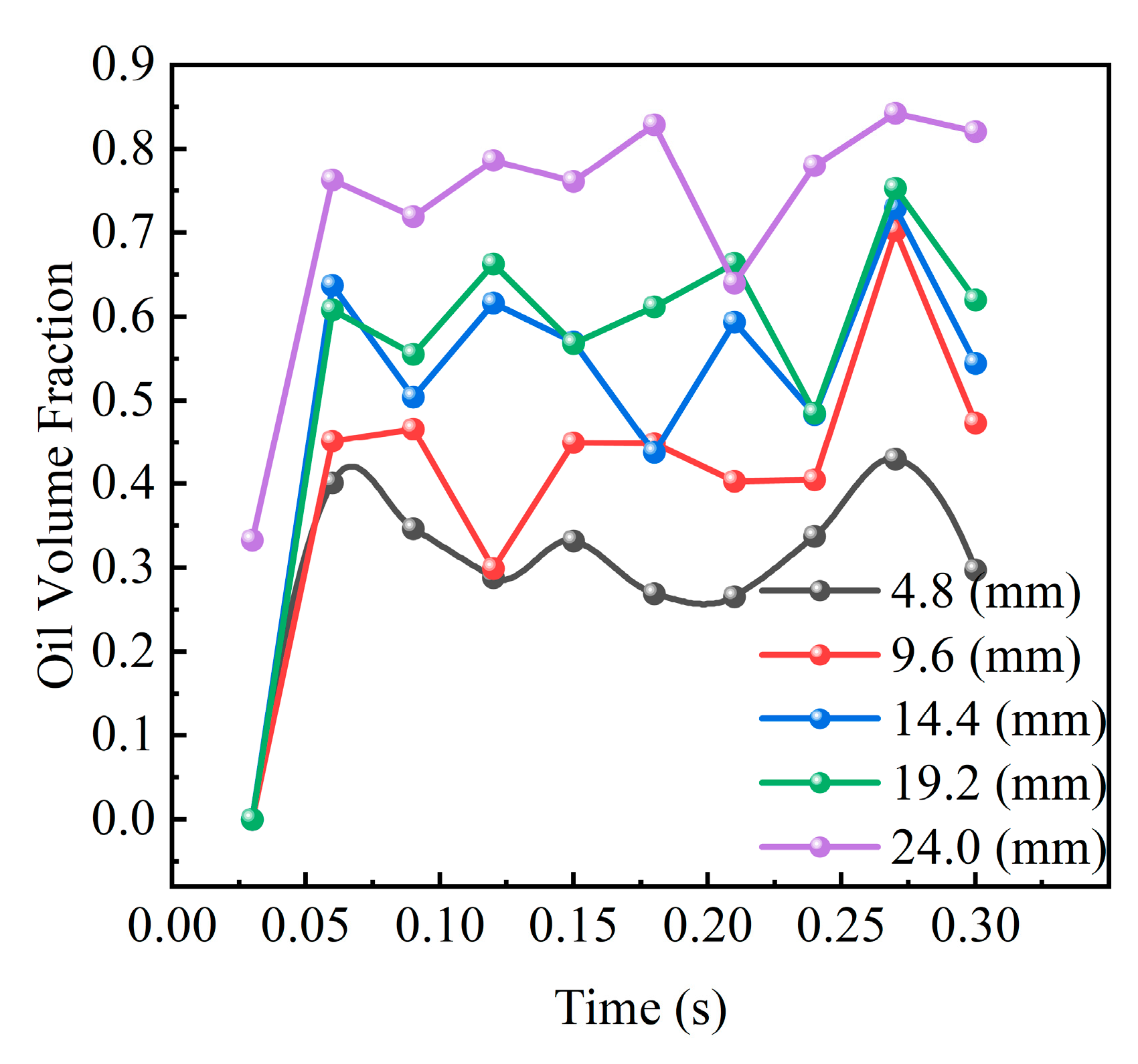
Then, the temporal evolution of oil volume fraction at monitoring point P was investigated, as depicted in
Figure 6. The figure illustrates the dynamic oil transport process during the initial lubrication phase under varying injection distances. The temporal profile reveals a rapid initial surge in the oil volume fraction at point P post lubrication commencement, indicating swift lubricant delivery and initial adhesion in the target zone. However, subsequent to this primary peak, all cases exhibit oscillatory fluctuations of varying magnitudes. This oscillation reflects the dynamic alternation between localized accumulation and drainage of lubricant under combined gear meshing motion and cyclic oil impingement, demonstrating the transient characteristics of lubrication distribution. These findings confirm significant coupling relationships among the oil injection distance, hydrodynamic parameters, and gear geometric configuration. Rational optimization of injection parameters and lubrication layout can effectively mitigate oil distribution heterogeneity. Such optimization enhances the integrity and stability of oil films in meshing zones, thereby improving both the system’s thermal management efficiency and operational reliability. The phase-dependent fluctuation patterns further suggest that synchronized control of injection timing with gear kinematics could potentially suppress transient distribution instabilities, offering new perspectives for precision lubrication strategies in high-performance gear systems.
4.2. The Influence of Different Injection Distances on the Oil Vortex Viscosity on Tooth Surfaces
In lubrication and thermal management studies of gear transmission systems, beyond investigating the dynamic characteristics of lubricant volume fraction distribution during gear meshing processes, the spatial distribution features of oil eddy viscosity—a critical parameter characterizing hydrodynamic behaviors—exert more profound influences on system performance through their underlying mechanisms. This section therefore specifically investigates the spatial distribution of oil eddy viscosity within the
xz-plane along the gear axial direction, as illustrated in
Figure 7. The analysis reveals distinct viscosity stratification patterns correlated with rotational dynamics and flow field interactions. High-viscosity zones predominantly concentrate near tooth engagement interfaces, while secondary vortices develop in inter-tooth spaces, demonstrating strong coupling between turbulent dissipation and centrifugal transport effects. Such viscosity heterogeneity fundamentally governs the energy transfer efficiency and thermal boundary layer development, providing critical insights for optimizing both lubrication supply strategies and heat dissipation architectures in precision gear systems.
At high-speed gear operation, the lubricant oil ejected from the nozzle exhibits an initially concentrated jet flow with substantial momentum, and subsequently undergoes gradual dispersion and expansion. Upon contacting rotating gears, the oil experiences intense shear and traction forces, being rapidly entrained into gear meshing zones to form vortex structures, and ultimately expelled from the system under centrifugal force. During this process, the oil’s eddy viscosity demonstrates pronounced spatial heterogeneity across different regions, particularly within the gear meshing zone and downstream areas where vorticity distribution manifests strong discreteness and complexity. At smaller injection distances, the oil fails to establish effective continuous flow structures, maintaining a low overall volume fraction. Consequently, the eddy viscosity displays highly discrete and chaotic distribution patterns. This unstable flow state reflects the lubricant’s inability to form continuous shear and adhesion layers on gear surfaces under such conditions, thereby compromising its capacity to mitigate shear-induced and frictional heat generation. As the oil injection distance increases (e.g., the 9.6 mm and 14.4 mm cases), the lubricant achieves improved momentum regulation and distribution uniformity, with its eddy viscosity gradually evolving toward ordered spatial patterns. Periodic “tooth-matching” structures emerge in the edge regions of gear tooth surfaces, indicating the formation of preliminary shear channels that facilitate oil adhesion and continuous flow. However, persistent gaps between the lubricant and gear surfaces, along with incomplete coverage in localized lubrication zones, suggest suboptimal lubrication performance at this stage. When the injection distance reaches 24 mm, the eddy viscosity distribution transitions to continuous patterns, particularly forming stable, extensive high-vorticity regions adjacent to tooth surfaces with enhanced flow stability. This characteristic distribution confirms that the lubricant not only establishes continuous oil films, but also develops favorable viscous shear properties. Such optimized flow features significantly enhance both the lubrication effectiveness and thermal transport efficiency, effectively mitigating the risks of thermal fatigue and wear induced by localized temperature spikes. The establishment of this coherent viscosity field demonstrates critical coupling between injection parameters and hydrodynamic performance, providing theoretical foundations for precision lubrication control in high-speed gear systems.
Additionally, this study further investigated the temporal evolution of the oil eddy viscosity at monitoring point P, with the results presented in
Figure 8. Located near the gear meshing zone, this monitoring point effectively captures the dynamic evolution of localized oil flow behavior and viscous characteristics during lubrication. The time-series data reveal a rapid escalation of eddy viscosity at point
P during the initial post-injection phase, indicating intensified local turbulence due to enhanced velocity gradients and shear effects as the lubricant initially coats tooth surfaces. Subsequently, the viscosity curve enters an oscillatory phase, before gradually approaching stabilization. This temporal pattern aligns closely with the spatial evolution of the oil velocity distribution and volume fraction discussed earlier, reflecting the viscous response of the lubricant during transient hydrodynamic processes such as vortex formation, adhesion, and detachment on tooth surfaces. The observed viscosity oscillations correlate with periodic gear engagement events, demonstrating frequency-locked behavior modulated by rotational kinematics. In conclusion, the oil injection distance exerts significant modulation effects on the evolutionary patterns of eddy viscosity. Rational parameter selection facilitates the establishment of continuous, stable lubricant vortex structures, thereby enhancing the dynamic lubrication performance and thermal stability of gear systems. The phase synchronization between viscosity stabilization and gear engagement frequency further suggests that optimized injection timing could amplify these benefits, offering a novel pathway for precision lubrication control in high-speed gear transmission.
4.3. The Influence of Different Injection Distances on the Turbulent Kinetic Energy of the Oil on Tooth Surfaces
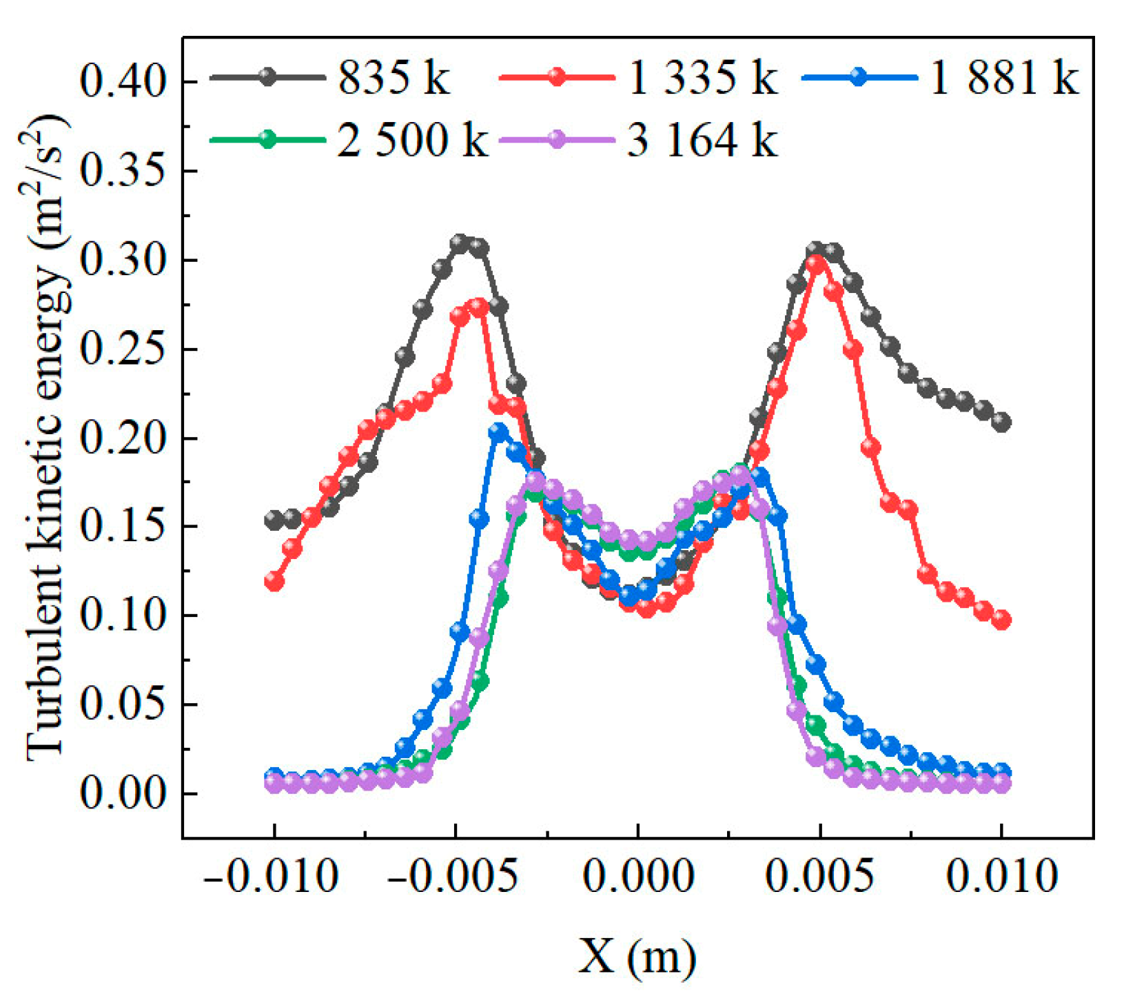
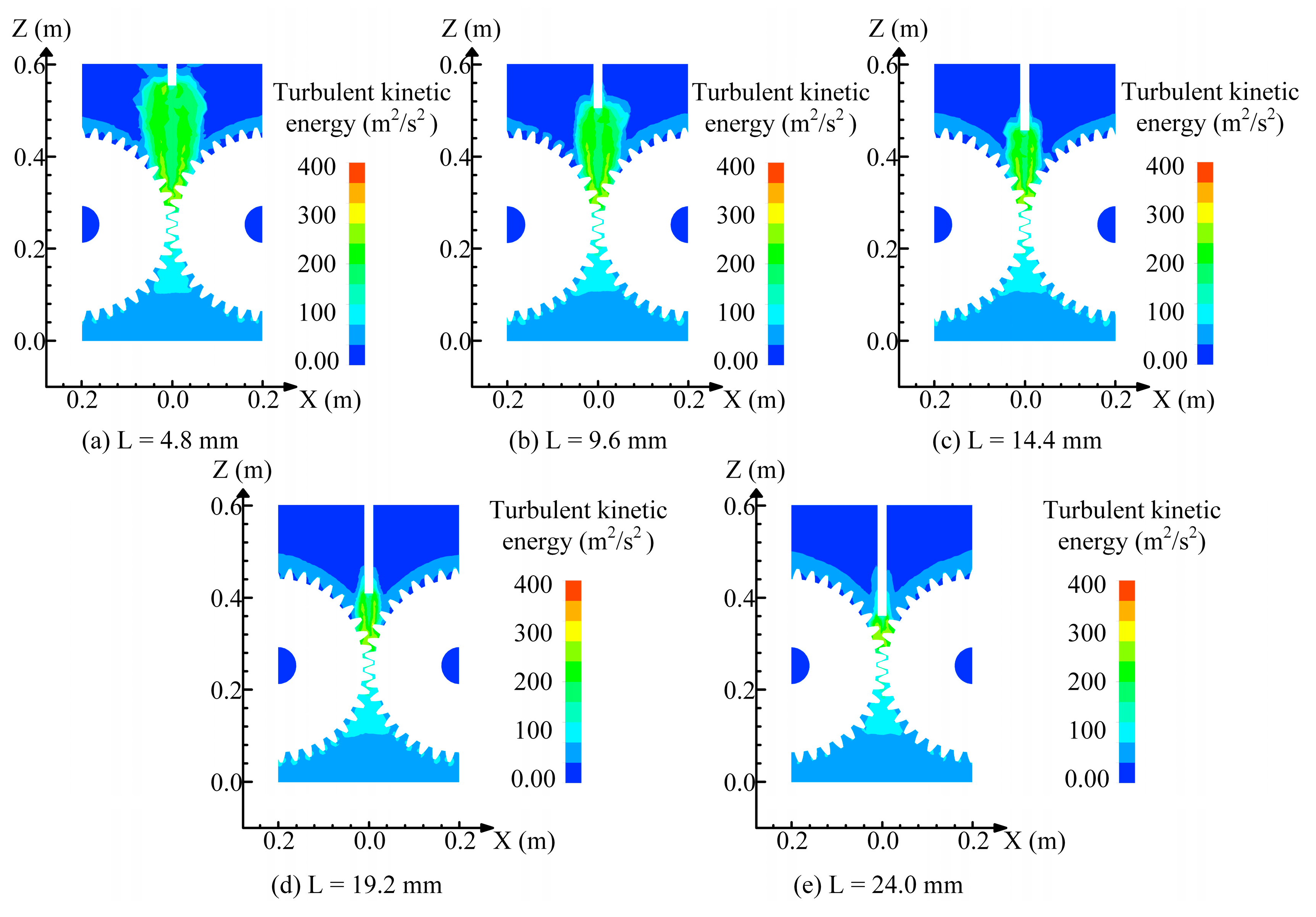
The turbulent kinetic energy at the nozzle exit constitutes a critical parameter governing oil jet characteristics, oil–tooth-surface interaction behaviors, and lubrication effectiveness. During high-speed gear lubrication processes, turbulent structures generated at the nozzle directly determine both the stability of oil transport to meshing zones and the formation of continuous and uniform lubricant films on tooth surfaces. To further elucidate the influence of injection dynamics on lubrication behaviors, this study conducted systematic investigations of turbulent kinetic energy spatial distributions under varying oil injection distances within the axial xy-plane of gears, as illustrated in
Figure 9.
The research demonstrates that under smaller oil injection distances (i.e., when the nozzle is positioned relatively far from gear surfaces), the lubricant undergoes significant velocity decay and flow field diffusion during its extended flight trajectory. This configuration allows fluid disturbances to accumulate and propagate freely in open space, resulting in spatially dispersed distributions of jet turbulent kinetic energy. Substantial turbulent energy dissipation occurs distantly from gear surfaces, leaving insufficient momentum and directional stability when the oil reaches tooth interfaces. Consequently, weak adhesion capability manifests during oil–surface contact, characterized by scattered and discontinuous lubrication patterns that degrade lubrication quality. Conversely, as the injection distance increases (i.e., the nozzle approaches gear surfaces), the oil maintains higher momentum and directional consistency along shortened trajectories. The turbulent kinetic energy becomes more concentrated near tooth surfaces, forming localized energy-accumulation zones that enable precise impingement on target lubrication areas. This spatial energy concentration significantly enhances oil spreading and adhesion capabilities on tooth surfaces. The centralized turbulent energy not only amplifies lubricant scouring efficiency, but also promotes the formation of continuous oil film structures. These optimized flow characteristics substantially improve both the lubrication performance and heat dissipation capacity in gear meshing zones. Mechanistically, the concentrated energy field facilitates synchronized interactions between turbulent momentum transfer and surface wettability, effectively bridging the gap between jet dynamics and interfacial lubrication requirements. This physical mechanism provides critical guidance for balancing injection parameters and tribological performance in high-speed gear systems.
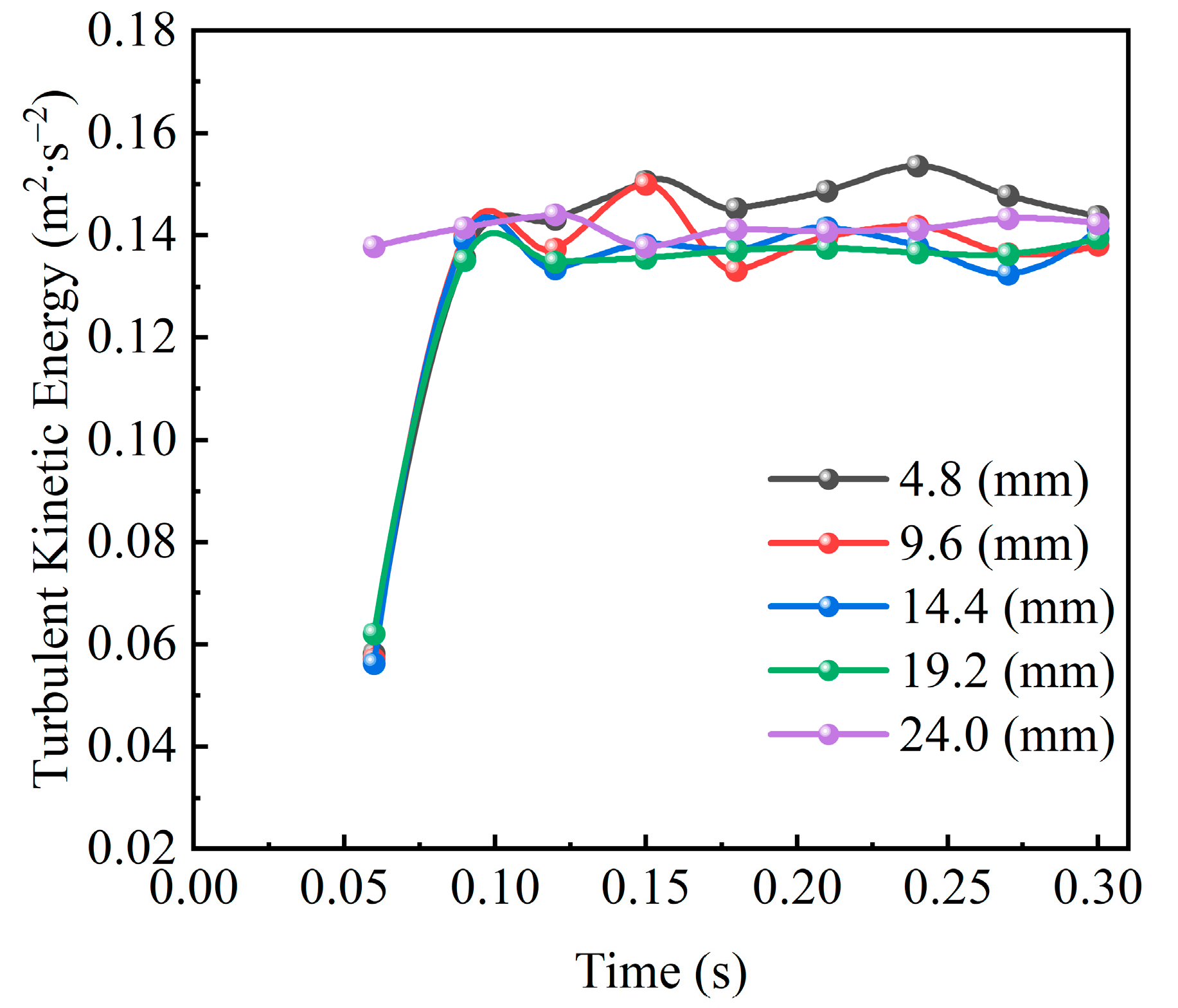
Moreover, the present study analyzes the temporal evolution of turbulent kinetic energy at monitoring point P, with the corresponding results illustrated in
Figure 10. This analysis provides deeper insights into how local flow field energy characteristics influence lubrication processes. Compared to the temporal variations in the oil volume fraction and eddy viscosity, the turbulent kinetic energy demonstrates relatively weak response discrepancies across different oil injection distances. The figure reveals that although all cases exhibit rapid initial escalation followed by oscillatory behavior during lubrication commencement, the overall fluctuation amplitudes and mean values show limited sensitivity to injection distance variations. These observations indicate that under rotational operating conditions, the oil injection distance does not predominantly govern the local turbulent intensity. Instead, local turbulence behaviors are likely co-regulated by the gear geometric configuration, lubricant inertia, and meshing-induced disturbances. The spectral analysis of turbulent energy fluctuations further demonstrates frequency components synchronized with gear rotational frequency, suggesting strong coupling between mechanical kinematics and hydrodynamic responses. In conclusion, while the oil injection distance significantly impacts the turbulent kinetic energy distribution—thereby influencing lubricant transport dynamics and lubrication performance—optimal lubrication system design requires holistic consideration of the matching relationship between injection parameters and gear structural features. Such integrated optimization enables synergistic enhancement of lubrication efficacy and thermal management capabilities, ultimately achieving balanced improvements in both the tribological performance and operational reliability of high-speed gear transmission systems. The frequency-dependent turbulence characteristics identified in this work additionally propose new criteria for vibration–lubrication coupling control strategies.
4.4. The Influence of Different Fuel Injection Distances on the Oil Velocity on Tooth Surfaces
To elucidate the effects of nozzle distance variations on oil motion behaviors, this study conducted comparative analyses of oil velocity field distributions under different nozzle distances, with the corresponding results presented in
Figure 11. The figure demonstrates significant impacts of oil injection distance on jet velocity distribution characteristics. When the oil injection distance is smaller (i.e., the nozzle is positioned farther from the gears, e.g., the 4.8 mm and 9.6 mm cases), the lubricant experiences substantial kinetic energy attenuation during extended flight paths before reaching the gears. The prolonged airborne propagation induces jet dispersion, resulting in a broader velocity field distribution with diluted main flow structures and reduced energy concentration. Conversely, with increased oil injection distances (i.e., the nozzle approaches the gears, e.g., the 19.2 mm and 24 mm cases), the contact path between the oil and tooth surfaces shortens significantly. The jet impinges on gear meshing zones before notable energy dissipation occurs, forming high-intensity, concentrated velocity cores. These optimized flow patterns enhance both adhesion efficiency and kinetic energy transfer in critical regions, creating favorable conditions for stable oil film formation. Mechanistically, the concentrated high-velocity jets promote synchronized momentum coupling between the lubricant and the rotating surfaces, effectively overcoming centrifugal separation effects. This dynamic interaction facilitates the establishment of coherent lubrication layers while suppressing secondary flow instabilities. The observed distance-dependent velocity modulation highlights the necessity for precision matching between injection parameters and gear rotational dynamics to achieve synergistic lubrication–thermal performance enhancements in high-speed transmission systems.
Furthermore, this study analyzed the temporal variation trend of the oil velocity at monitoring point P, with the relevant results illustrated in
Figure 12. The figure reveals periodic fluctuations in oil velocity over time. Notably, the oil velocity demonstrates limited sensitivity to nozzle distance. As the distance between the nozzle and the monitoring point gradually increases, the oscillation amplitude of the oil velocity decreases significantly, indicating that greater nozzle distances contribute to reduced velocity fluctuation magnitudes. This phenomenon correlates with fluid diffusion and enhanced stability during propagation. In conclusion, the nozzle distance exerts a substantial regulatory effect on both the oil velocity field distribution and lubrication performance. The rational selection of nozzle position therefore serves as one of the critical design parameters for optimizing gear lubrication systems.
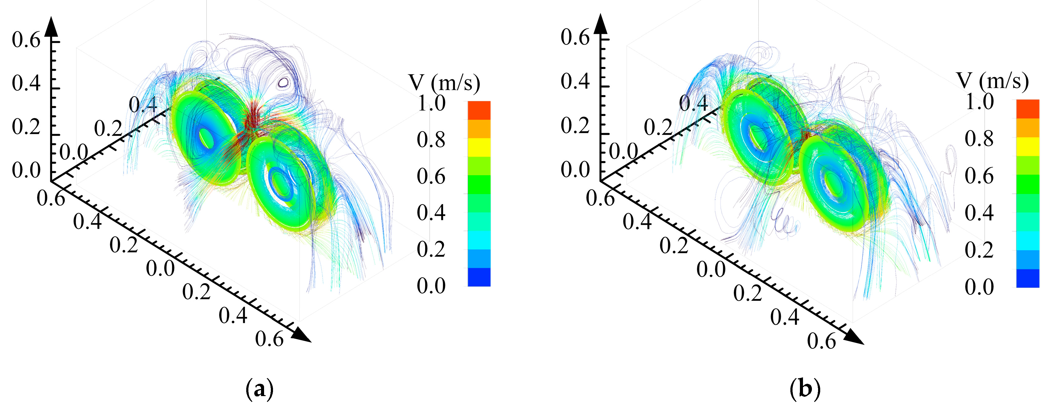
To further investigate the relationship between the oil injection distance and hydrodynamic behavior, this study conducted a detailed analysis of velocity streamline distributions under oil injection distances of 14.4 mm and 24 mm, as illustrated in
Figure 13. When the oil injection distance is 14.4 mm (
Figure 13a), the oil exhibits energy dissipation and rebound phenomena after impacting the meshing zone, in addition to entering the meshing region. Specifically, the oil experiences significant disturbances at this distance, with partial kinetic energy converting into thermal energy or redistributing through rebound effects. These rebound phenomena may lead to irregular streamlines, complicating the flow dynamics and potentially compromising the stability and efficiency of the oil injection system. In contrast, when the oil injection distance increases to 24 mm (
Figure 13b), the streamline distribution becomes more uniform and stable. At this distance, the oil flow demonstrates enhanced stability without noticeable streamline dispersion or rebound effects, allowing kinetic energy to transfer more efficiently to the target area. The extended injection distance reduces fluid disturbance and energy loss, resulting in more controllable and efficient hydrodynamic behavior. These findings highlight the critical influence of appropriate oil injection distances on hydrodynamic performance, emphasizing their role in minimizing unnecessary energy losses and improving the overall system efficiency. The results provide robust insights for optimizing the design of oil injection systems and regulating hydrodynamic behavior, offering practical significance for enhancing injection efficiency, reducing energy consumption, and achieving precise control.
5. Conclusions
This study addresses the optimization of lubrication performance in high-speed gear reducers. A lubrication dynamics model was constructed based on the VOF two-phase flow model and the standard k-ε turbulence model to analyze the influence of oil injection distance on the dynamic characteristics of oil films in gear meshing zones. Through parametric design, the regulatory mechanisms of oil injection distance on oil distribution, energy dissipation, and thermodynamic behavior were investigated, providing a theoretical foundation for the optimization of lubrication systems.
(1) A reduction in the oil injection distance significantly enhances both the coverage and continuity of tooth-surface oil films. When the injection distance decreases from 24 mm to 4.8 mm, the oil distribution in the meshing zone transitions from discrete droplets to a dense wedge-shaped oil film, accompanied by an increased peak volume fraction. Near-field injection imparts higher initial kinetic energy to the oil, overcoming air resistance and centrifugal separation effects while suppressing the risks of secondary atomization and lubrication failure. Concurrently, continuous high-vorticity zones emerge near tooth surfaces due to eddy viscosity, with turbulent kinetic energy concentrating in the near-field meshing region, thereby improving the oil film’s shear-load capacity and thermal conduction efficiency.
(2) An optimized oil injection distance markedly reduces oil velocity fluctuations and energy dissipation. Dynamic data from monitoring point P demonstrate that shorter injection distances decrease velocity oscillation amplitudes and significantly enhance flow field stability. Furthermore, reduced oil transport paths minimize turbulent kinetic energy diffusion losses in free space, directing energy more efficiently toward surface lubrication. At the 24 mm injection distance, stabilized oil flow avoids streamline rebound and disordered energy dissipation, improving the directional transport efficiency of the lubricant.
(3) Multiphysics coupled simulations revealed dynamic interaction mechanisms between injection parameters and lubrication performance. A reduced injection distance enhances the spatial stability of the eddy viscosity, curbs excessive turbulent energy dissipation, and optimizes oil film shear and thermal management characteristics. Synergy between the gear rotation and oil inertia promotes continuous oil film adhesion on tooth surfaces, while equilibrium between the gas–liquid interfacial tension and Coriolis forces governs the spatiotemporal evolution of oil distribution patterns.
This study establishes a quantitative evaluation framework for low-power-consumption design and thermal management strategies in gearbox lubrication systems. Precise control of the oil injection distance can substantially improve gear transmission efficiency, reduce churning losses, and extend service life. The findings not only advance theoretical understanding of lubrication mechanisms in high-speed transmission, but also provide technical support for the design of lightweight, high-reliability industrial equipment, offering significant engineering implications for advancing green manufacturing and sustainable development.


