Article

Study on Friction and Wear Performance of Bionic Function Surface in High-Speed Ball Milling

1
School of Mechanical and Electronic Engineering, Qiqihar University, Qiqihar 161006, China
2
Key Laboratory of Advanced Manufacturing and Intelligent Technology, Harbin University of Science and Technology, Ministry of Education, Harbin 150080, China
3
QiQiHar Heavy CNC Equipment Co., Ltd., Qiqihar 161005, China
4
The Engineering Technology Research Center for Precision Manufacturing Equipment and Industrial Perception of Heilongjiang Province, Qiqihar 161006, China
5
The Collaborative Innovation Center for Intelligent Manufacturing Equipment Industrialization, Qiqihar 161006, China
6
School of Mechatronics Engineering, Harbin Institute of Technology, Harbin 150001, China
*
Author to whom correspondence should be addressed.
Machines 2025, 13(7), 597; https://doi.org/10.3390/machines13070597
Submission received: 5 June 2025 / Revised: 2 July 2025 / Accepted: 7 July 2025 / Published: 10 July 2025
(This article belongs to the Section Friction and Tribology)

Abstract

During the service life of automotive panel stamping dies, the surface is often subjected to high loads and repeated friction, resulting in excessive wear. This leads to die failure, reduced machining accuracy, and decreased production efficiency. To enhance the anti-friction and wear-resistant performance of die steel surfaces, this study introduces the concept of biomimetic engineering in surface science. By mimicking microstructural configurations found in nature with outstanding wear resistance, biomimetic functional surfaces were designed and fabricated. Specifically, quadrilateral dimples inspired by the back of dung beetles, pentagonal scales from armadillo skin, and hexagonal scales from the belly of desert vipers were selected as biological prototypes. These surface textures were fabricated on Cr12MoV die steel using high-speed ball-end milling. Finite element simulations and dry sliding wear tests were conducted to systematically investigate the tribological behavior of surfaces with different dimple geometries. The results showed that the quadrilateral dimple surface derived from the dung beetle exhibited the best performance in reducing friction and wear. Furthermore, the milling parameters for this surface were optimized using response surface methodology. After optimization, the friction coefficient was reduced by 21.3%, and the wear volume decreased by 38.6% compared to a smooth surface. This study confirms the feasibility of fabricating biomimetic functional surfaces via high-speed ball-end milling and establishes an integrated surface engineering approach combining biomimetic design, efficient manufacturing, and parameter optimization. The results provide both theoretical and methodological support for improving the service life and surface performance of large automotive panel dies.

1. Introduction

With the advancement of biomimetic engineering concepts in the field of material surface science, more and more researchers are applying natural micro-nano structures to the design of wear resistance in machined surfaces. Biomimetic design shows great potential in improving surface performance, especially in enhancing wear resistance, corrosion resistance, and friction reduction. Zhang Wei et al. [1] used the surface structure of dung beetles as a prototype and fabricated a quadrilateral biomimetic pit structure through high-speed milling, finding that this structure significantly improved surface wear resistance. Yu Wang et al. [2] utilized femtosecond laser technology to create shark-skin textures on tool surfaces, enhancing the wettability and service life of the tools. Sheng et al. [3] pointed out that biomimetic microstructures significantly improve the wear resistance and service life of materials by enhancing their tribological properties. Specifically, biomimetic micro-pits and grooves effectively reduce friction and wear, showing potential for applications in cutting tool surfaces.
Wear is a key factor affecting the service life and performance of mechanical parts, and, therefore, optimizing surface structures to improve wear resistance has become a research focus. Zheng Xiaohui et al. [4], based on Archard’s wear theory and combined with DEFORM-3D simulation, analyzed the wear characteristics of hot stamping molds; simultaneously, orthogonal tests were used to optimize processing parameters, significantly improving die life. Lin Xiang et al. [5] used biological forms such as fish scales and shells as templates to create biomimetic micro-textures on medical titanium alloy surfaces, improving surface hardness and reducing wear by over 70%. Xiao et al. [6] systematically reviewed the optimization and application of micro-texture friction reduction technologies, emphasizing the key role of multi-physical field coupling simulation in biomimetic structure design. You C et al. [7] a biomimetic cutting tool was designed and prepared based on the microstructure of the dung beetle head. The biomimetic microstructure effectively reduced cutting force and friction coefficient, significantly improving the wear resistance and service life of the tool. Liu Jiangnan et al. [8] proposed a surface design scheme based on snake-scale-like hexagonal textures combined with a coal dust filling mechanism, achieving a synergistic improvement in the self-lubrication and wear resistance of steel. In addition, Sachin Kumar Sharma et al. [9] summarized the inspirations from natural surface structures, emphasizing that combining multi-scale structures and micro-nano texture technologies can effectively regulate friction and adhesion behavior at the contact interface, thereby slowing down the wear process.
High-speed milling, as an advanced machining method, is widely applied to improve material surface quality and performance. To enhance the wear resistance of workpieces and molds under harsh conditions, various surface reinforcement technologies, such as milling, laser processing, and electron beam treatments, are widely used in material surface processing. Zhao Changlong et al. [10] combined laser surface texturing with laser cladding technology, significantly improving the surface hardness and friction performance of Cr12MoV die steel under oil-deprived lubrication conditions, making the composite-treated sample exhibit optimal wear resistance. Hu et al. [11] studied the performance of self-lubricating micro-textured ball-end mills under dry cutting and micro-lubrication conditions, finding that it significantly reduced cutting forces and friction coefficients while improving machined surface quality. Additionally, Wang Rong et al. [12] regulated the microstructure of the material surface by scanning electron beam impact, not only reducing surface roughness but also effectively enhancing wear resistance, providing a new approach to improving the service life of cold work die steel. Etsion [13] used laser technology to prepare specific micro-textures on the surface of mechanical parts, significantly improving their tribological performance. Yerramareddy and Bahadur [14] investigated the effects of laser surface melting, nitriding, and nickel alloying on the tribological behavior of Ti-6Al-4V, demonstrating that these treatments significantly improved dry sliding wear resistance and altered the dominant wear mechanism from ploughing to adhesion. Similarly, Mondal et al. [15] applied Nd:YAG laser treatment to ACM720 magnesium alloy, achieving a twofold increase in surface hardness and notable reductions in both corrosion and wear rates, primarily attributed to grain refinement and solid solution strengthening. Kedong Zhang et al. [16] studied the impact of micro-nano texturing and MoS2 as a lubricant on the tribological performance of TiAlN coatings, demonstrating that surface texturing and lubricants can effectively improve coating wear resistance and reduce friction. Wang et al. [17] examined the influence of EDM-fabricated dimple geometries on friction under boundary and mixed lubrication conditions, revealing that circular dimples provided superior friction reduction compared to other shapes, highlighting the importance of dimple design in tribological optimization. Altug Bakirci et al. [18] systematically analyzed the high-feed milling of AISI H13 steel, clarifying the effects of feed rate and cutting speed on tool wear and residual stress, proposing optimized cutting parameters to extend tool life and improve residual stress distribution. José V. Abellán-Nebot et al. [19] analyzed various factors affecting surface roughness in machining and proposed strategies to improve machining sustainability by optimizing cutting conditions, selecting appropriate tools, and adopting eco-friendly cooling systems. Li Rongyi et al. [20] constructed an accurate milling force prediction model for the impact behavior of ball-end mills in the die splicing area and experimentally verified its impact on machining accuracy. Najeeb Ullah et al. [21] systematically summarized the critical role of milling in precision machining from a sustainable manufacturing perspective.
Although biomimetic non-smooth surfaces have made significant progress in enhancing material surface properties in recent years, there is still a lack of systematic research on the friction and wear behavior of biomimetic micro-textured surfaces fabricated by high-speed ball-end milling. Most existing studies focus on special processing techniques, such as laser machining, which, although capable of producing fine surface structures, suffer from high costs, limited processing areas, and heavy dependence on specialized equipment. These limitations hinder their applicability in the efficient and cost-effective manufacturing of large automotive stamping dies. Therefore, there is an urgent need to develop a biomimetic surface fabrication method with strong engineering adaptability. Inspired by the surface structures of typical crawling organisms, this study designed three types of biomimetic micro-textures with different dimple geometries, which were efficiently fabricated on Cr12MoV die steel using high-speed ball-end milling. The friction and wear performance of these surfaces was systematically evaluated through a combination of finite element simulations and dry sliding wear experiments. The aim of this study is to evaluate the friction and wear performance of different biomimetic surface textures and to identify the optimal structure and machining parameters for enhancing the surface performance of die steel. The novelty of this work lies in the introduction of high-speed ball-end milling—a conventional and efficient machining method—into the fabrication of biomimetic functional surfaces. This approach overcomes the limitations of special processing techniques in die manufacturing and expands the practical application of biomimetic design to the efficient production of large-scale dies. The results provide important engineering value and practical significance for improving the wear resistance and friction-reducing performance of die steel surfaces, extending tool life, and reducing manufacturing costs.

2. Materials and Methods

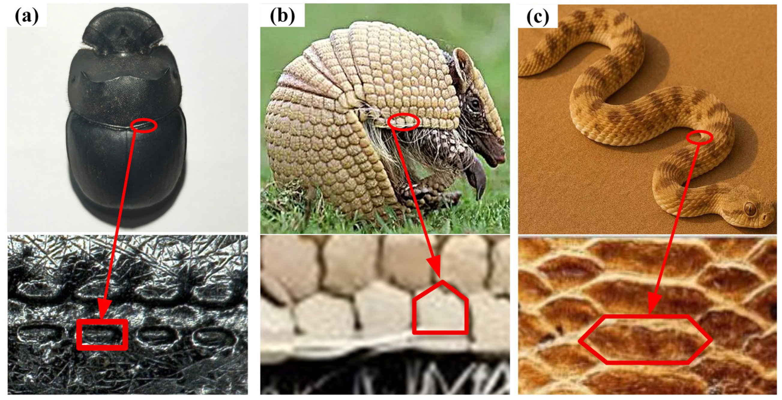
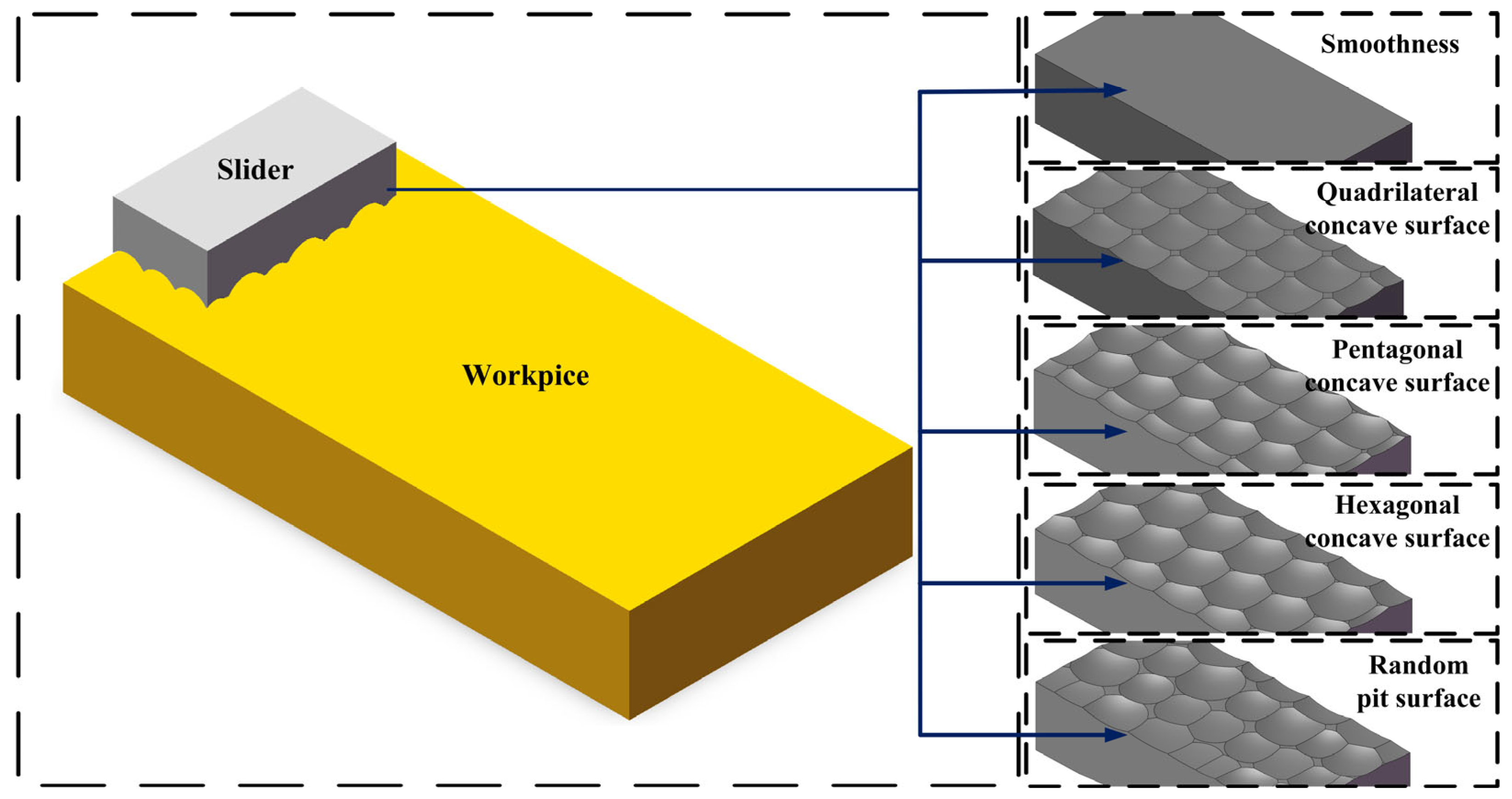
2.1. Selection of Biomimetic Prototypes and Establishment of Models

Research has shown that crawling organisms in nature, such as dung beetles, armadillos, and desert snakes, have gradually formed microstructures with excellent wear reduction and abrasion resistance on their surfaces over a long period of evolution. These structures exhibit excellent anti-adhesion, drag reduction, and anti-wear properties, and have important potential for engineering biomimicry. Therefore, this study selected these three animals as biomimetic prototypes and introduced their typical surface microstructures into the design of microstructure surface sliders, in order to improve their frictional performance. Specifically, during the process of pushing heavy objects (such as with dung balls), dung beetles are less likely to adhere to soil on their surfaces. Their backs are concentrated with quadrilateral pits, which can effectively reduce surface adhesion and friction by reducing the actual contact area and storing air. The surface of the armadillo is composed of sheet-like pentagonal scales, with small gaps between the scales, which endow its outer skin with both flexibility and rigidity; it can cushion external friction and impact during movement, disperse stress concentration, and demonstrate good wear resistance. The surface of the abdomen of desert venomous snakes presents a highly ordered, regular hexagonal scale arrangement, with tightly connected scales and certain sliding ability. Its geometric regularity and directionality help significantly reduce frictional resistance during the sliding process. The unique advantages of these animal body surface structures provide important biomimetic insights for the construction of high-performance wear-resistant surfaces. Figure 1 shows the biomimetic micro-pit structure morphology extracted based on three biological prototypes.
In this study, the surface characteristics of the dung beetle, armadillo, and sidewinder snake were selected as bionic prototypes to design three types of dimple structures: quadrilateral, pentagonal, and hexagonal. Corresponding 3D solid models were constructed using SolidWorks (Dassault Systèmes, Waltham, MA, USA, Version 2023), as shown in Figure 2. The upper specimen (slider) has dimensions of 4 mm × 2 mm × 1 mm, while the lower specimen measures 12 mm × 6 mm × 2 mm.

2.2. Friction and Wear Theory

A wear model under dry sliding friction conditions was established based on Archard’s classical wear theory [22]. This theory reveals a quantitative relationship between wear and material hardness, sliding distance, and load, as expressed in Equation (1).
V = K F s H
In the formula, V is the wear volume, F is the normal load, s is the sliding distance, H is the hardness of the softer material in contact, and K is the wear coefficient. The calculation formula for wear depth can be obtained from Formula (1) as follows:
A h = K F s H
where A is the actual contact area, h is the wear depth. After solving, the following formula was obtained:
h = K σ s H
where σ is the normal contact stress (Pa) applied during sliding. In the actual wear process, Wear is generally considered to increase with the accumulated sliding distance, which is the product of sliding speed and time v = d s / d t . By taking the derivative, we can obtain the following:
d h d t = K σ v H
The theoretical model of wear depth can be obtained by integrating Formula (4) as follows:
h = K σ v H d t

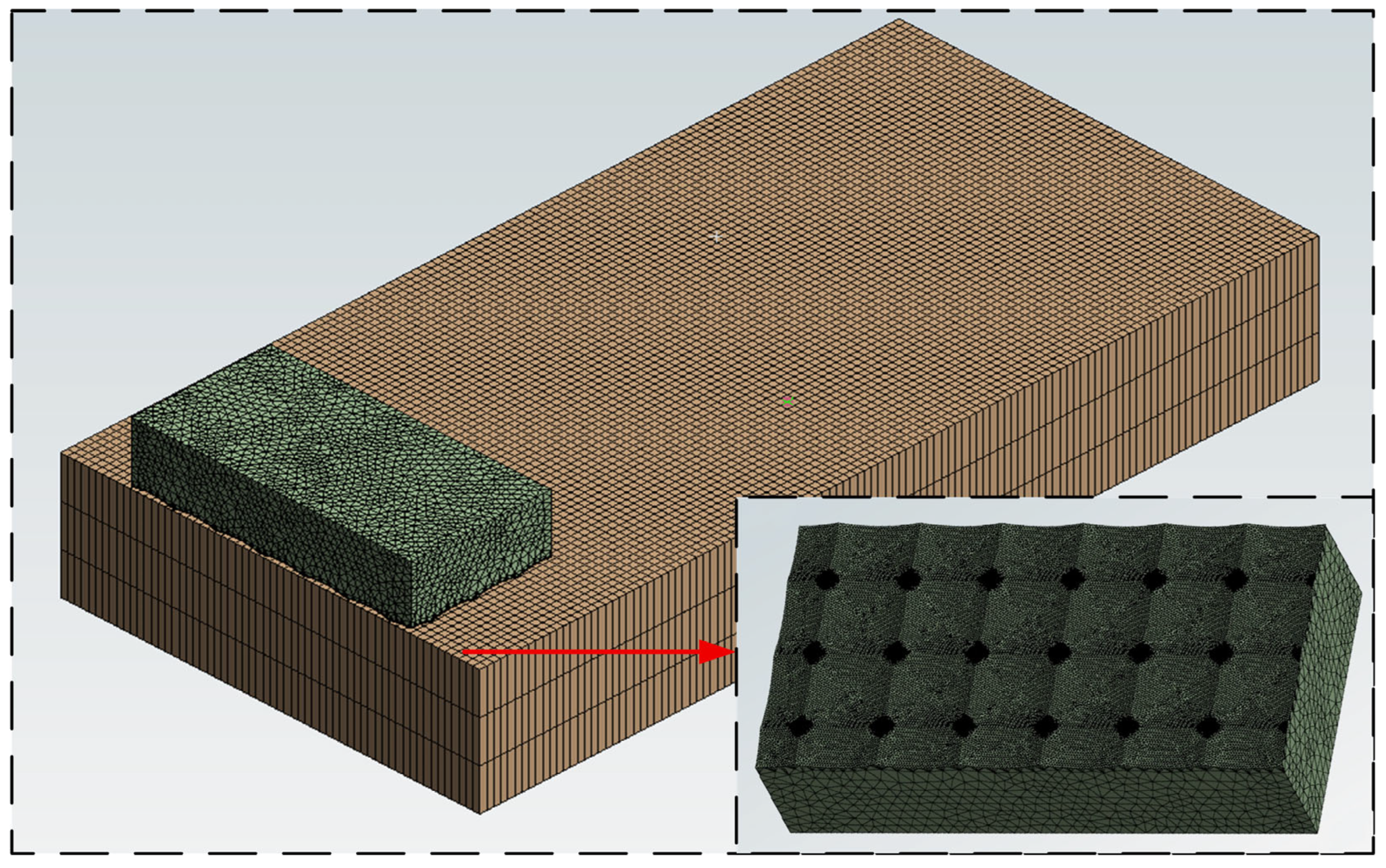
2.3. Preprocessing of Finite Element Simulation

The model was imported into ANSYS Workbench (ANSYS, Canonsburg, PA, USA, Version 2023) for finite element simulation of friction and wear behavior. In the finite element model, the specimen material was hardened Cr12MoV die steel, and its main chemical composition is listed in Table 1. To ensure the validity of comparative results, all bionic pit models maintained consistent parameters, such as pit size (side length and depth), array configuration (regular arrangement), and material properties, with only the geometric shape of the pits being varied.
In the contact settings of the friction pair, the upper specimen (the side containing the bionic pits) was defined as the contact surface, and the lower specimen (the workpiece surface) was defined as the target surface. The friction coefficient was set to the average value of 0.4 as determined by tribological testing [23]. The loading and boundary conditions were as follows: equivalent normal pressure and tangential friction force were applied on the top surface of the upper specimen to simulate the actual contact load in milling; frictionless supports were applied to both sides of the upper specimen, and the bottom of the lower specimen was fixed. Material parameters are listed in Table 2.
Table 1. Composition of Cr12Mov Material [24].
ElementCCrMoVMn
Content1.45–1.7011.00–12.500.4–0.60.15~0.30≤0.40
ElementSiNiCuSP
Content≤0.40≤0.25≤0.30≤0.030≤0.030
Table 2. Material Parameters [24].
Density
(kg/m3)
Young’s Modulus (GPa)Poisson’s RatioThermal Conductivity (W·m−1·K−1)Specific Heat Capacity (J·kg−1·K−1)
7.72180.2824460
To ensure the accuracy of the contact mechanics and wear simulation, a multi-scale meshing strategy was adopted in ANSYS Workbench. As shown in Figure 3, the bottom specimen (workpiece) was meshed uniformly with a global element size of 0.1 mm. For the upper specimen (slider), different mesh resolutions were applied depending on the functional role of each surface. All non-contact surfaces of the slider were meshed with a standard element size of 0.1 mm to maintain computational efficiency. The bottom surface of the slider, which interacts directly with the workpiece, was subdivided into two critical zones: the concave pit regions and the actual contact areas. The concave pit regions were meshed with a finer resolution of 0.02 mm to accurately replicate the complex geometry of the biomimetic textures. The contact regions were assigned an ultra-fine mesh size of 0.0005 mm to enhance the resolution of stress, temperature, and wear calculations. This hierarchical mesh configuration ensured both numerical convergence and high fidelity in capturing localized tribological phenomena.

2.4. Design of Experiments

In this study, the fabrication of biomimetic pit structures on Cr12MoV die steel specimens was carried out using a DMU 60 monoBLOCK five-axis high-speed vertical machining center(DMG MORI company, Pfronten, Bavaria, Germany), as illustrated in Figure 4. The cutting tool used in this experiment is a 20 mm diameter ball-end milling cutter produced by Daijie Company located in Tokyo, Japan. The machining parameters were set as follows: a tilt angle of 30°, radial line spacing (ae) of 0.45 mm, feed per tooth (fz) of 0.45 mm/tooth, axial depth of cut (ap) of 0.5 mm, and a spindle speed of 10,000 rpm. The resulting surface roughness (Ra) was measured to be in the range of 0.35–0.45 μm, indicating a high level of fidelity in replicating the designed micro-texture geometries. The milling morphology can be observed by a white light interferometer (Xiamen Jinlu, Xiamen, China) as shown in Figure 5a, where the surface pits of the beetle have a quadrilateral pit morphology with a depth of 10~20 μm, a length of 100~200 μm, and a width of 70~100 μm. The surface of the milled biomimetic quadrilateral pit is shown in Figure 5b.
The friction and wear tests were conducted using an MFT-5000 tribometer (manufactured by Rtec Instruments, San Jose, CA, USA) under dry sliding conditions. The sliding stroke was 25 mm, with a frequency of 5 Hz and a normal load of 80 N. The total test duration was 6 min. According to these parameters, the reciprocating sliding occurred approximately 4200 times, resulting in a total sliding distance of about 105 m. The experimental setup and procedure are illustrated in Figure 6a. To ensure the accuracy of the test results, all specimens (as shown in Figure 6b) were cleaned with an alcohol solution before and after testing, and their masses were measured using an electronic balance with a precision of 1 mg. The wear resistance of the specimens was evaluated by comparing the mass loss before and after the test.

2.5. Optimization Design of Milling Parameters

To further improve the wear reduction performance of the concave structure, this study optimized the machining parameters. Firstly, the Plackett–Burman (PB) experimental design was used to preliminarily screen the milling parameters, from which the three main influencing factors were determined to be the line spacing ae (A), feed rate fz (B), and cutting depth ap (C). Each factor is set at three levels (specific level values are shown in Table 3). Subsequently, using the wear volume as the response value, a Box–Behnken experimental design with three factors and three levels was adopted to construct a response surface model, and corresponding simulation experiments were completed (see Table 4 for the experimental plan and results) [25].

3. Simulation Analysis of Different Bionic Functional Surfaces

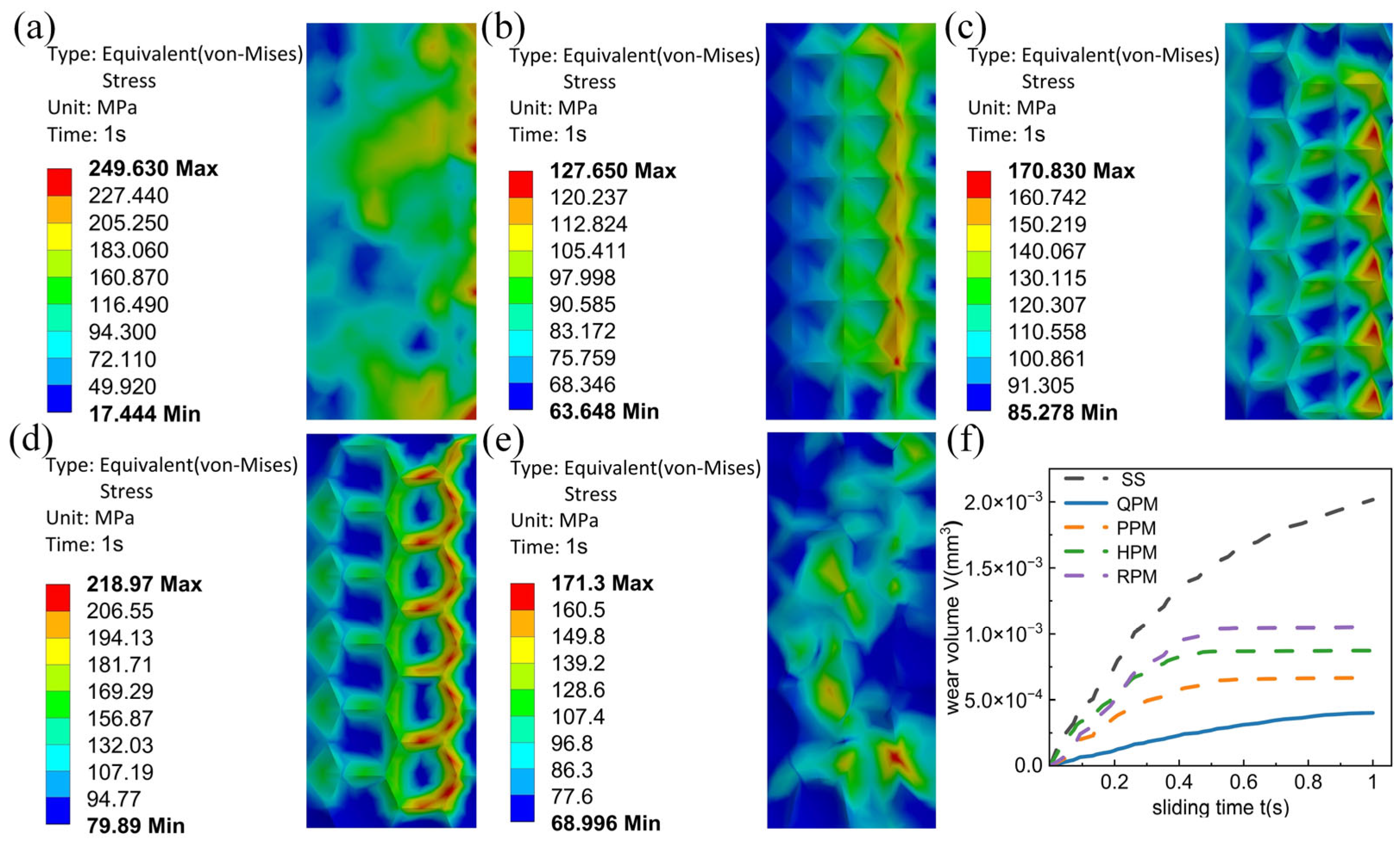
3.1. Simulation Analysis of Wear Volume for Different Bionic Functional Surfaces

Figure 7 compares the wear volume distribution contour maps and maximum wear volumes of different bionic functional surfaces under dry sliding contact. The smooth surface specimen Figure 7a exhibits the most severe wear, with a maximum wear volume reaching 2.02 × 10⁻³ mm3. The wear region is extensively distributed across the central area of the contact interface, indicating that the smooth surface lacks anti-wear capability and is highly prone to large-scale material loss. In contrast, the quadrilateral dimpled bionic surface Figure 7b demonstrates the best wear resistance, with a maximum wear volume of only 4.02 × 10⁻⁴ mm3, which is significantly lower than that of the other bionic surfaces. This performance can be attributed to the geometrical symmetry of the quadrilateral pit structure, which ensures even distribution of applied loads, reduces localized stress concentrations, facilitates efficient debris storage, and lowers the effective contact area, leading to lower friction coefficients, improved wear resistance, and reduced abrasive wear compared to irregular shapes like the random pit morphology [8]. The pentagonal and hexagonal dimpled surfaces Figure 7c,d show maximum wear volumes of 6.66 × 10⁻⁴ mm3 and 8.74 × 10⁻⁴ mm3, respectively. Although these values are markedly lower than that of the smooth surface, they are still higher than that of the quadrilateral dimpled surface, suggesting that their anti-friction effects are less effective. The randomly distributed dimpled surface specimen Figure 7e, due to uneven pit spacing and fluctuations in initial residual height, leads to localized stress concentrations and non-uniform wear distribution. Its maximum wear volume reaches 1.05 × 10⁻³ mm3, which is close to that of the smooth surface. In summary, among all the surface textures examined in this study, the quadrilateral dimpled bionic surface exhibits the most outstanding wear resistance performance.
Figure 7f shows the variation of wear volume over time for different biomimetic surface structures in sliding contact within 1 s. The overall trend shows that the wear volume of all samples accumulates continuously over time, but there are significant differences in the growth rate. Among them, the smooth surface (SS) consistently exhibits the highest wear volume, indicating that it is prone to severe plastic deformation and abrasive particle detachment during sliding. In contrast, the quadrilateral concave surface (QPM) has the lowest wear volume and the smoothest growth curve throughout the entire process, verifying its excellent anti-wear and drag reduction characteristics, which is highly consistent with the cloud map results. The pentagonal (PPM) and hexagonal concave (HPM) surfaces exhibit a moderate level of wear reduction ability, with higher wear resistance than smooth surfaces but lower than quadrilateral concave surfaces; the surface with randomly distributed pits (RPM) exhibits a certain wear suppression ability in the initial stage, but the overall wear volume is higher than that of regular structures and close to the level of smooth surfaces, indicating limited wear reduction performance of its structure. Overall, the quadrilateral concave biomimetic structure has the best anti-wear performance.

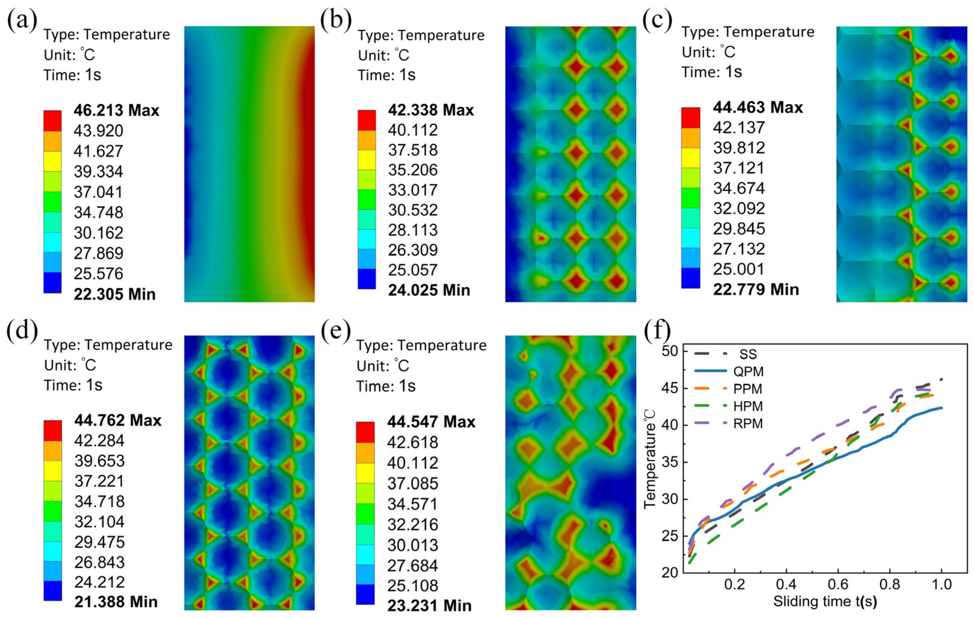
3.2. Simulation Analysis of Wear-Induced Temperature for Different Bionic Functional Surfaces

The friction-induced thermal behavior of different bionic surfaces is shown in Figure 8. The smooth surface Figure 8a exhibited the highest contact temperature, with a maximum value of 46.213 °C. The high-temperature region was extensively distributed across the contact area, indicating a strong tendency for thermal accumulation during friction. By comparison, the quadrilateral pattern exhibited in Figure 8b showed a significantly lower maximum temperature of only 42.338 °C. The temperature rise was primarily confined to the edges of the dimple units, and the overall temperature distribution was relatively uniform. This suggests that the quadrilateral dimple structure facilitates effective dissipation of frictional heat and reduces surface thermal accumulation. The maximum temperatures of the pentagonal Figure 8c, hexagonal Figure 8d, and randomly distributed dimpled surfaces Figure 8e were 44.463 °C, 44.762 °C, and 44.547 °C, respectively. These values were close to one another but slightly higher than that of the quadrilateral structure, indicating their relatively weaker ability to mitigate frictional heat generation. Overall, the quadrilateral dimpled bionic surface exhibited the best performance in reducing friction-induced temperature rise.
Figure 8f shows the temperature evolution trends of different bionic functional surfaces during 1 s of sliding contact. Overall, the surface temperatures of all samples continued to rise over time, reflecting the continuous accumulation of frictional heat. The smooth surface maintained the highest temperature throughout the process, consistent with the temperature contour maps, indicating that without surface texturing, interfacial frictional heat is difficult to dissipate, leading to thermal accumulation. Notably, the quadrilateral dimpled surface exhibited the best thermal dissipation performance, with the lowest rate of temperature rise. Its regular structure promotes air circulation and heat diffusion while reducing the actual contact area, effectively suppressing frictional heating. The pentagonal and hexagonal dimpled surfaces followed similar temperature rise paths, with slightly higher final temperatures than the quadrilateral surface, suggesting a certain heat dissipation capability, though not as effective. The randomly distributed dimpled surface maintained higher temperatures than other regular structures and approached the level of the smooth surface. This indicates that its irregular dimple arrangement and discontinuous local heat conduction paths limit its thermal dissipation capacity. In summary, the quadrilateral dimpled bionic structure demonstrated the best heat dissipation performance among all the tested surface designs.

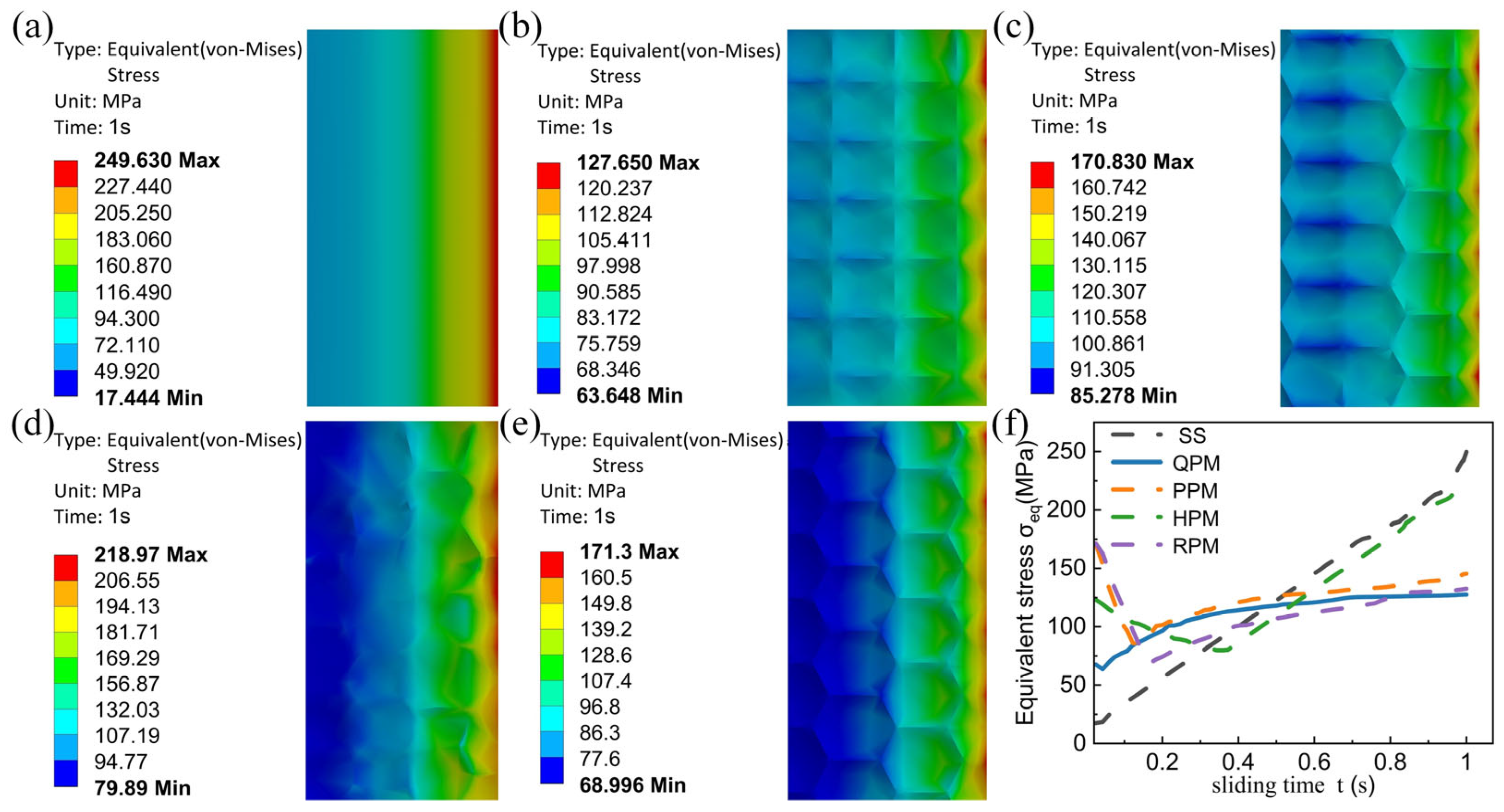
3.3. Simulation Analysis of Equivalent Stress Distribution for Different Bionic Functional Surfaces

Figure 9 presents the von Mises equivalent stress distributions of different bionic functional surfaces under 1 s of sliding contact. Overall, the surface structures have a significant impact on the distribution and concentration of stress. The smooth surface Figure 9a exhibited the most pronounced stress concentration, with a maximum equivalent stress reaching 249.63 MPa. The high-stress region appeared as a strip along the central contact zone, indicating that untextured surfaces are prone to forming continuous high-stress zones under load, which can induce plastic deformation and fatigue damage. In contrast, the quadrilateral dimpled surface Figure 9b showed the lowest maximum equivalent stress of only 127.65 MPa, with a uniform stress distribution and only minor concentration at the edges. This indicates a strong stress dispersion capability and suggests that this structure effectively mitigates stress concentration and provides excellent stress relief performance [1]. The pentagonal Figure 9c, hexagonal Figure 9d, and randomly distributed dimpled surfaces Figure 9e exhibited higher maximum equivalent stresses of 170.83 MPa, 218.97 MPa, and 171.30 MPa, respectively. These structures displayed relatively larger stress concentration zones at the edges, indicating their limited ability to alleviate localized loading and deformation, resulting in lower structural stability. In summary, the quadrilateral dimpled bionic surface demonstrated superior stress relief performance compared to the other surface morphologies examined.
Figure 9f illustrates the evolution of equivalent stress (von Mises) over a 1-s sliding process for different surface structures. All surface types exhibited an initial rapid change in stress followed by a gradual stabilization phase, though significant differences were observed in their stress responses. The smooth surface showed a continuous and rapid stress increase, ultimately exceeding 250 MPa, indicating persistent stress accumulation in the frictional contact zone. This suggests poor stress relief capability, which can lead to plastic failure under sustained loading. Among all tested structures, the quadrilateral variant stood out for displaying the most stable stress curve. Although a slight stress increase was observed in the early stage, the curve entered a slow growth phase after 0.35 s, indicating that the regular structure effectively dispersed the contact load, mitigated stress transmission, and provided strong buffering capacity. For the pentagonal, hexagonal, and randomly distributed dimpled surfaces, a distinct turning point occurred in the 0.1–0.25 s interval, where the stress initially decreased and then rose again. This phenomenon is attributed to incomplete load-bearing by some dimple units during the initial contact. As sliding progressed, the actual contact area expanded, and the microstructures gradually participated in load transmission, facilitating local stress release and redistribution. Among them, the hexagonal surface exhibited the most prominent turning point, suggesting uneven load transmission in the early stage and a higher tendency for stress mutation zones. In summary, the quadrilateral dimpled surface not only maintained the lowest overall equivalent stress level but also exhibited the best performance in stress dispersion and relief throughout the sliding process.

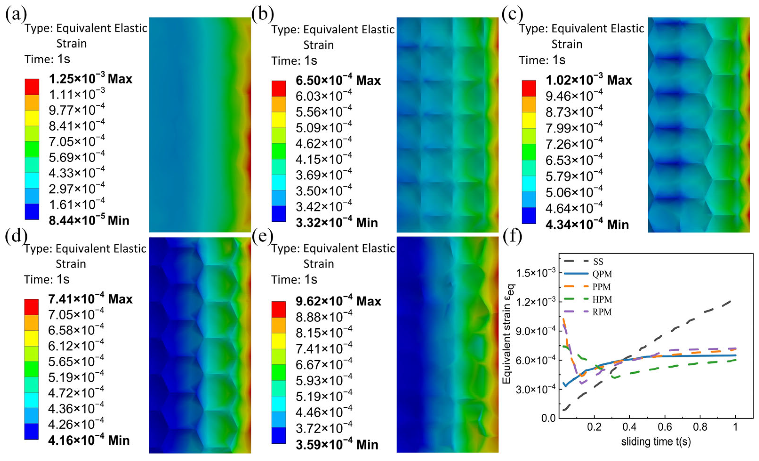
3.4. Simulation Analysis of Equivalent Elastic Strain for Different Bionic Functional Surfaces

Figure 10 illustrates the equivalent elastic strain distribution of different biomimetic surfaces at 1 s under sliding contact. This metric effectively reflects the deformation and fatigue resistance of surface structures under applied loads, indirectly indicating the machining quality and service stability of the workpiece surface. Among them, the smooth surface in Figure 10a exhibits the most severe strain concentration, with a maximum equivalent elastic strain reaching 1.2500 × 10⁻³, primarily distributed at the edge of the contact region. This indicates that, in the absence of structural modification, elastic deformation tends to accumulate locally, leading to instability, thus revealing poor deformation-bearing capacity and inadequate surface adaptability. In contrast, the quadrilateral dimpled biomimetic surface shown in Figure 10b exhibits the lowest maximum strain value of 6.5015 × 10⁻⁴, approximately half that of the smooth surface. The strain distribution is uniform and stable, with only slight local concentration around the dimples, demonstrating excellent load transfer and deformation resistance. This reflects a higher level of surface machining quality and stress relief efficiency [8]. The pentagonal Figure 10c, hexagonal Figure 10d, and randomly distributed dimpled surfaces Figure 10e present maximum strain values of 1.0200 × 10⁻³, 7.4160 × 10⁻⁴ and 9.6276 × 10⁻⁴, respectively. Although these values are slightly better than that of the smooth surface, they are all higher than that of the quadrilateral dimpled structure. Moreover, they show significant strain concentration at the edges, indicating inferior deformation coordination and load distribution capacity. As a result, their overall surface quality and mechanical response stability are not as favorable as those of the quadrilateral configuration. In summary, the quadrilateral dimpled biomimetic surface demonstrates the most superior performance in controlling equivalent elastic strain, indicating enhanced machining effectiveness and service reliability.
Figure 10f illustrates the evolution of equivalent elastic strain (εeq) over a 1-s sliding process for different bionic surface structures. Overall, except for the smooth surface, all other textured structures exhibit a distinct turning point at the early stage, indicating a phase-wise variation in strain response during dynamic contact. The strain on the smooth surface increases continuously and eventually exceeds 1.5 × 10⁻³, the highest among all surfaces, suggesting severe accumulation of contact-induced deformation due to the absence of structural stress-relief features. In contrast, the quadrilateral dimple surface shows the most stable strain growth, with no significant fluctuations in the curve. This implies that its regular geometry effectively guides the strain distribution and relieves stress, demonstrating excellent resistance to deformation. The pentagonal, hexagonal, and randomly textured surfaces all exhibit turning points between 0.1 and 0.2 s, characterized by an initial rapid increase in strain followed by a brief drop before stabilizing into a steady rise. This behavior is mainly attributed to the incomplete load-bearing state during early contact, where non-uniform engagement leads to transient high-strain zones. As sliding progresses, more dimples become involved in the contact and contribute to redistributing local loads, thereby stabilizing the overall strain response. Notably, the hexagonal structure shows a more pronounced turning point due to its more complex unit boundaries, indicating a tendency toward strain concentration. In summary, the quadrilateral dimple bionic surface not only achieves the lowest strain level but also demonstrates superior stability during the sliding process.

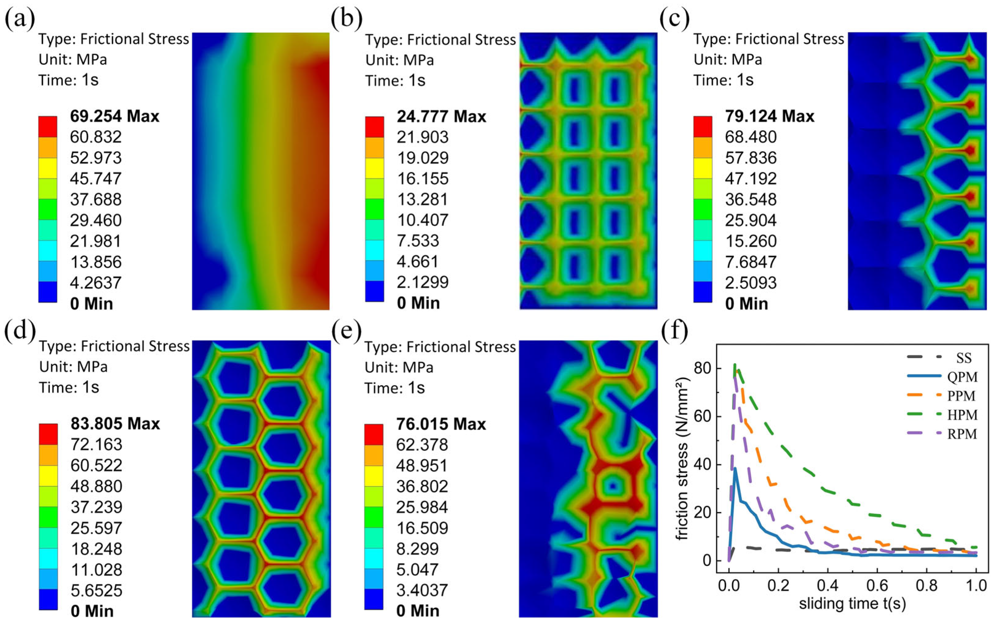
3.5. Simulation Analysis of Frictional Stress on Different Bionic Functional Surfaces

Figure 11a–e present the frictional stress contour maps of different bionic surfaces during the sliding contact process. For the smooth surface Figure 11a, a large high-stress zone is observed, with a maximum frictional stress reaching 69.254 MPa. This indicates that the applied load is highly concentrated on the non-textured surface, resulting in significant sliding resistance, continuous frictional heating, and a high risk of adhesive wear. In contrast, the quadrilateral dimple surface Figure 11b exhibits a maximum frictional stress value of only 24.777 MPa. The stress distribution is relatively uniform, with localized high values appearing only around the edges of the dimples. This demonstrates the structure’s excellent ability to disperse contact loads and reduce localized shear stress, making it a favorable low-friction design. For the pentagonal Figure 11c and hexagonal Figure 11d dimple surfaces, the maximum frictional stresses are significantly higher at 79.124 MPa and 83.805 MPa, respectively. These stresses are mainly concentrated at the junctions of the dimple edges, suggesting poor continuity in the boundary transitions, which tends to cause stress concentration. The randomly distributed dimple surface Figure 11e shows a maximum frictional stress of 76.015 MPa and multiple irregular stress hotspots. This reflects the lack of continuity and geometric regularity in its texture arrangement, resulting in limited effectiveness in reducing frictional stress. In summary, the quadrilateral dimple bionic surface demonstrates the best performance in reducing interfacial frictional stress among all the structures evaluated.
Figure 11f illustrates the evolution curves of frictional stress over time for different bionic surfaces during the sliding process. All samples exhibit a typical “running-in” behavior, characterized by an initial sharp increase in frictional stress reaching a peak, followed by a rapid drop and a gradual stabilization. During the early contact stage (0–0.1 s), the frictional stress of each surface rises steeply to its peak and presents a clear inflection point. Among them, the hexagonal dimple surface shows the highest peak stress, approximately 90 N/mm2, which then decays rapidly. This suggests that at the onset of sliding, the surface asperities are intensely engaged in contact, leading to severe stress concentration. In contrast, both the quadrilateral dimple surface and the smooth surface show relatively lower initial peak stresses and more gradual curve rises, with delayed inflection points. This indicates that the quadrilateral dimple structure can effectively reduce initial shear resistance and mitigate abrupt stress transitions, thereby demonstrating excellent running-in and friction-reduction characteristics. As the reciprocating sliding continues, surface asperities are progressively flattened, leading to an increase in real contact area and a reduction in shear resistance. Consequently, the frictional stress rapidly declines after the peak and gradually stabilizes. Although the smooth surface maintains a generally low level of frictional stress due to the absence of texture-induced interference, its wear resistance and thermal durability are comparatively inferior.
In summary, aside from the smooth control surface, the quadrilateral dimple bionic surface exhibits the most favorable characteristics in terms of initial peak stress and curve stability during the steady-state phase. This reflects its superior capability in frictional stress mitigation and further confirms its potential as an effective friction-reducing surface design.

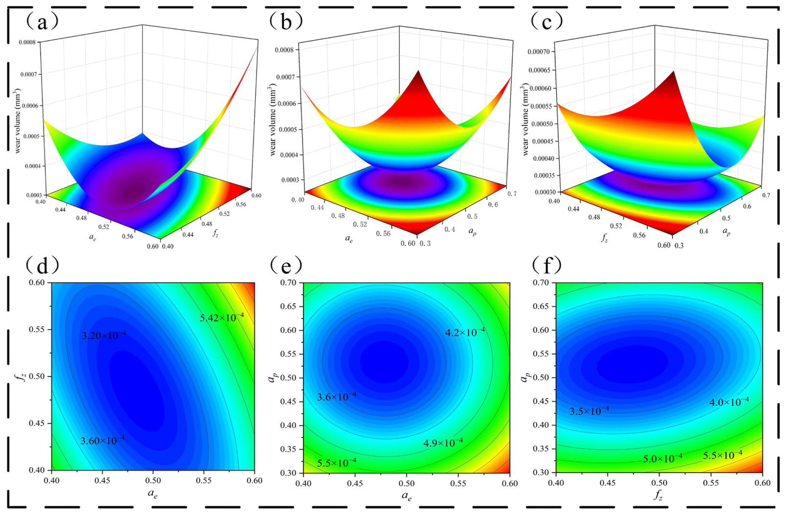
4. Optimization Design of Machining Parameters
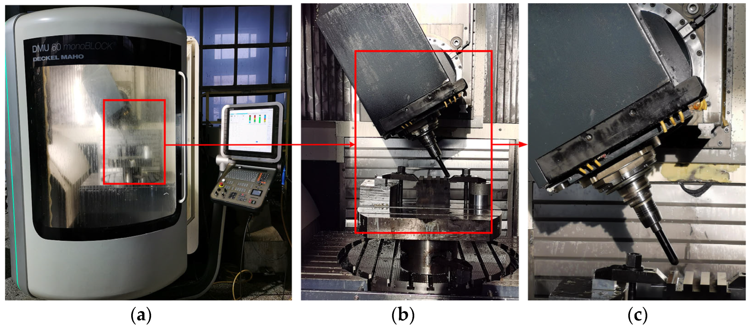
Based on the results of the finite element simulations presented in Section 3, the quadrilateral concave structure demonstrated superior performance in terms of wear resistance and friction reduction. Therefore, only this structure was selected for practical experimental validation. This focused approach ensures a meaningful comparison between the simulation and experimental results while avoiding redundancy in testing less effective geometries [26]. The results of the three-factor simulation experiment based on the Box–Behnken response surface design are shown in Table 5. Using Design Expert software Version 13.0.5 (Stat-Ease Inc., Minneapolis, MN, USA) to perform quadratic regression fitting on the wear volume response values, the regression equations of the wear volume with respect to various factors are obtained as follows:
Y = 0.009 − 0.022A − 0.011B − 0.004C + 0.011AB + 0.0003AC − 0.001BC + 0.017A2 + 0.006B2 + 0.004C2
The coded values of factors A, B, and C correspond to the normalized levels of radial spacing ae, feed per tooth fz, and axial depth of cut ap, respectively. The analysis of variance (ANOVA) results are shown in Table 5. The regression model is highly significant, with a model p-value less than 0.0001, indicating a strong overall fit. The regression demonstrates good fitting performance. The order of significance of the three process parameters on wear volume is radial spacing ae (A) > axial depth of cut ap (C) > feed per tooth fz (B). The lack-of-fit p = 0.7616 > 0.05, indicating no significant lack of fit and suggesting that the experimental error has negligible influence on the response values. Thus, the model exhibits good stability and reliability.
Furthermore, Table 5 shows that the coefficient of determination is R2 = 0.9891, implying that the model has an excellent goodness-of-fit and can reliably predict the trend of wear volume as a function of machining parameters. The adjusted Radj2 = 0.9751, indicating that 97.51% of the variability in the data can be explained by the model. The predicted Rpre2 = 0.9467, and the coefficient of variation C.V. = 5.35% < 10%, confirming the high reliability of the regression equation and its ability to accurately represent the actual values. The adequate Precision = 23.4964 > 4, which is well above the acceptable threshold of 4.0, providing further evidence of the model’s high predictive capability and excellent agreement with the experimental data.
The response surface analysis revealed the influence patterns of individual factors and their interactions on the wear volume. As shown in the contour plot of Figure 12, the wear volume exhibits a decreasing-then-increasing trend with changes in radial spacing ae (A) and axial depth of cut ap (C), indicating a significant interaction between these two factors. The minimum wear volume occurs when both factors are at moderate levels. The contour lines appear nearly circular, further suggesting a strong interaction between ae (A) and ap (C), with both factors exerting comparable influence on wear performance. Similarly, the contour plots for ae (A)—fz (B), fz (B)—ap (C) also demonstrate interaction effects. The interaction between ae (A) and fz (B) is relatively weak, as indicated by slightly elliptical contour lines, while the interaction between fz (B) and ap (C) is more pronounced [27].
By analyzing the regression model, the optimized combination of processing parameters can be determined. When the line spacing ae = 0.48 mm, feed per tooth fz = 0.49 mm, cutting depth ap = 0.53 mm, the wear volume response reaches the minimum value predicted by the model. From this, it can be inferred that the parameter combination is the optimal high-speed milling process parameter obtained through optimization in this study.

5. Empirical Test

To verify the accuracy of simulation analysis conclusions, this study conducted friction and wear experiments on various biomimetic structural samples and compared and analyzed them with surface microstructure.

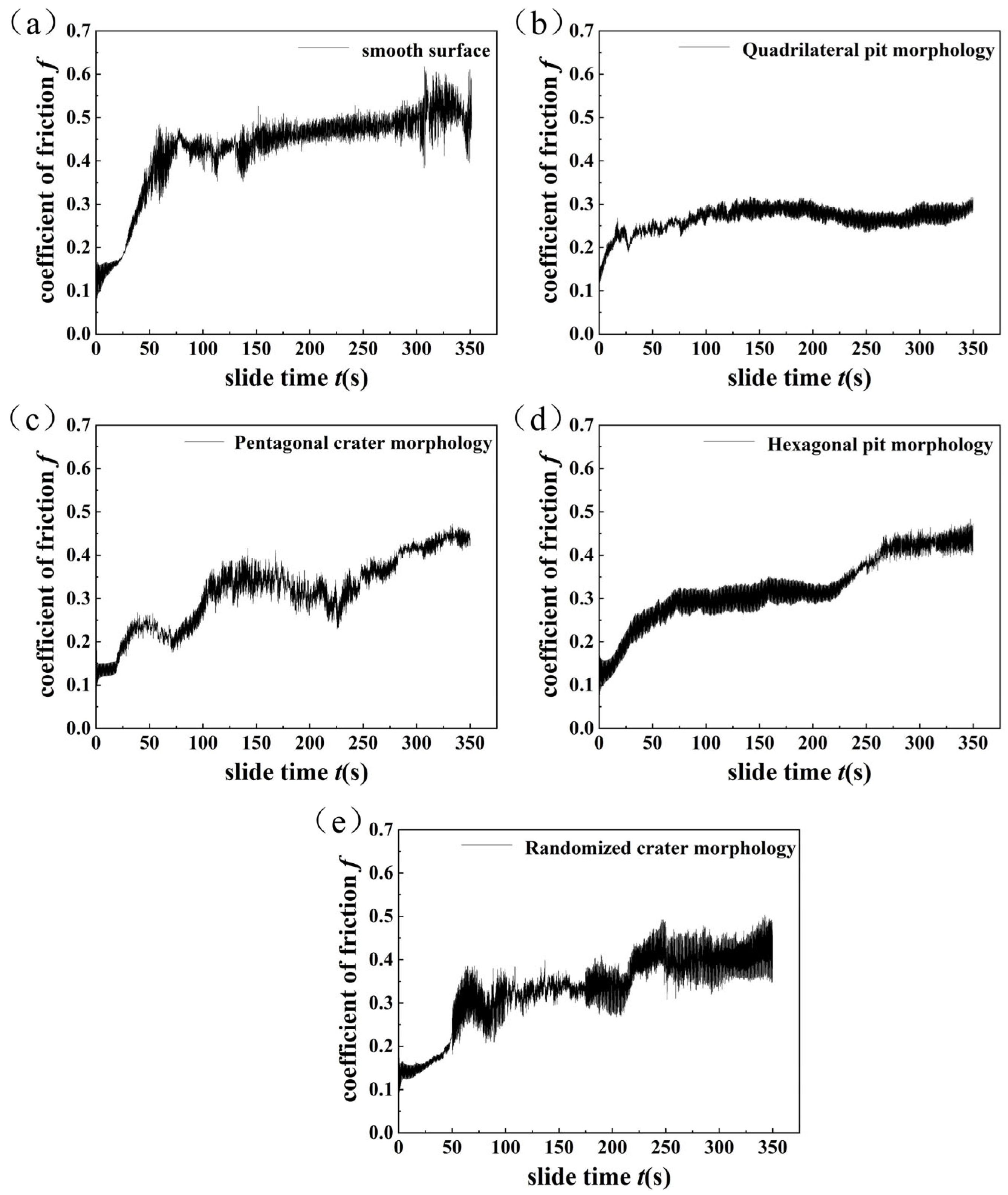
5.1. Friction Coefficient Analysis

According to the curves of friction coefficient versus time for specimens with different bionic surface morphologies, as shown in Figure 13, distinct variations can be observed among the samples. The polished surface specimen Figure 13a exhibits a friction coefficient ranging from 0.45 to 0.55, characterized by significant adhesive wear and unstable fluctuations. The pentagonal dimple surface Figure 13c shows a friction coefficient in the range of 0.40–0.48, while the hexagonal dimple surface Figure 13d presents a slightly lower range of 0.33–0.48. The randomly textured surface Figure 13e displays a friction coefficient between 0.30 and 0.43, but with large fluctuations and poor stability. Among all the samples, the quadrilateral dimple surface Figure 13b demonstrates the lowest friction coefficient, ranging from 0.28 to 0.33. It also has the shortest running-in period and enters the stable wear stage most rapidly. This indicates superior friction-reducing performance compared to the other four surface morphologies. In summary, regular dimple textures, particularly quadrilateral patterns, can significantly shorten the running-in time and improve anti-friction performance, outperforming both smooth and randomly textured surfaces in terms of wear resistance.

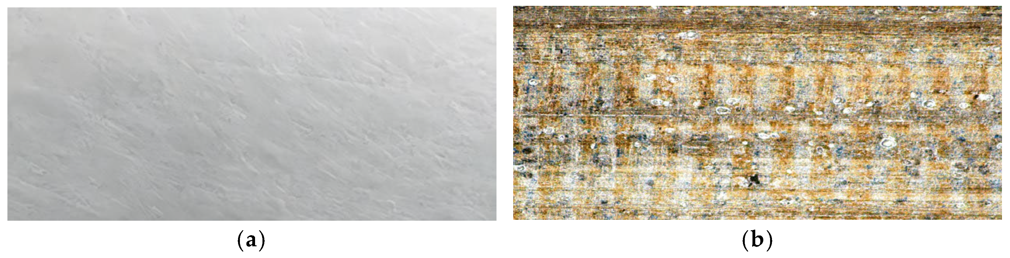
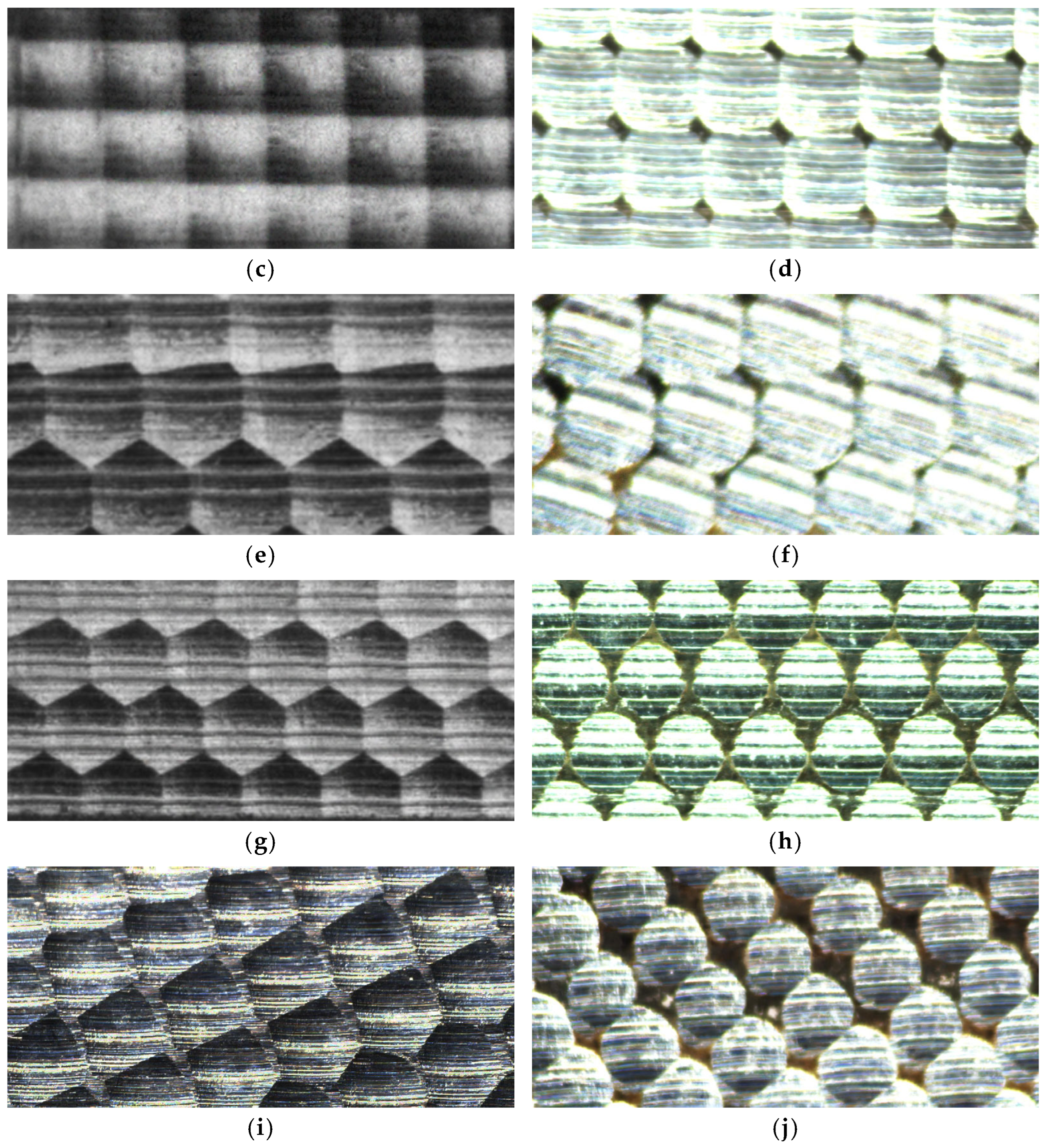
5.2. Wear Morphology Analysis

To validate the conclusions drawn from the simulation analysis, practical friction and wear tests were conducted on specimens with different bionic surface morphologies. The worn surface morphologies were then compared and observed. As shown in Figure 14, typical bionic surfaces before and after wear are presented for direct comparison.
Smooth specimen Figure 14a,b show that before wear, the overall surface is relatively smooth, with few surface defects and only slight scratches, demonstrating good surface integrity. The surface roughness of the smooth specimen significantly increases after wear, with obvious features such as brushed grooves, embedded abrasive particles, pits, peeling, and thermal oxidation spots, which better confirms the correctness of the numerical simulation results. By analyzing the wear mechanism, it can be concluded that the hard carbide particles in the matrix fall off under friction to form wear debris, resulting in a large number of shallow pit defects on the surface. Furthermore, due to the absence of concave structures on the smooth surface, it is unable to accommodate abrasive debris, resulting in increased wear of the contact surface by abrasive particles. By comparing and analyzing Figure 14c,d, it can be seen that the morphology of the quadrilateral biomimetic pit remains relatively stable before and after the wear test, and its structural characteristics are still clear and distinguishable, with only slight wear marks appearing at the two short edge lines. It is worth noting that a large amount of black carbide particles and debris have accumulated inside each pit unit, which fully proves that the quadrilateral biomimetic pit structure has excellent debris collection and storage performance. From the analysis of Figure 14e,f, it can be seen that the pentagonal concave biomimetic surface has a complete structure, clear concave edge, regular arrangement, and good geometric orderliness before wear. After reciprocating sliding friction, the edge of the pit became dull and partially peeled off, and the surface micro-texture became blurred. The degradation of the pentagonal concave structure leads to the weakening of its original lubrication and friction-reducing functions. Due to the limited chip space of pentagonal pits compared to quadrilateral pits, small debris is squeezed and rubbed between the pits, further exacerbating local wear. This also indirectly confirms the advantages of the quadrilateral concave biomimetic structure in collecting and storing debris. For the hexagonal pit biomimetic surface samples Figure 14g,h, the edge of the pit morphology was not very prominent before the wear test. After experiencing reciprocating friction, the hexagonal pit gradually eroded into an elliptical shape, and a small amount of debris residue can be seen inside the pit, indicating that the structure still has a certain ability to accommodate debris. However, compared to the biomimetic surface with quadrilateral pits, hexagonal pits can store a smaller amount of debris, and the vast majority of debris is compressed and repeatedly rubbed on the surface, thus accelerating surface wear. This experimental observation is consistent with the frictional stress and temperature distribution results obtained from previous simulations. The wear behavior of randomly distributed concave surface samples Figure 14i,j exhibits instability. Before wear, irregularly distributed pits have uneven heights, with local protrusions having higher heights than the surrounding ordered pit structures. Therefore, in the early stages of wear, these protruding areas experience wear first. As wear progresses, the originally low height areas (including the location of the quadrilateral pits) gradually participate in contact and wear occurs. Continuous reciprocating sliding leads to an increasing contact area, and continuous accumulation of carbide debris, resulting in increased frictional resistance and triggering severe abrasive wear. Ultimately, the cumulative wear amount and wear rate of randomly distributed pit samples were significantly higher than those of regularly arranged quadrilateral, pentagonal, and hexagonal pit samples. The experimental results are consistent with the conclusions of the previous numerical simulation, which verify the significant uncertainty in the drag reduction and wear resistance performance of the random irregular pit structure at the experimental level.

5.3. Wear Rate Analysis

Figure 15 shows the comparison of mass loss rates of samples with different surface morphologies in wear experiments. As shown in the figure, the smooth surface sample has the highest mass loss rate, indicating that its wear resistance is the worst during the friction process. In contrast, surfaces with regular quadrilateral pits exhibit the best wear resistance, with the lowest mass loss rate. Other surfaces with pit structures, such as pentagonal pits, hexagonal pits, and randomly distributed pits, show better wear resistance than smooth surfaces. This indicates that appropriately designed biomimetic pit textures can effectively reduce material wear during friction and improve surface wear resistance. In summary, surface structures with regular geometric shapes have significant advantages in reducing mass loss, among which the quadrilateral pit structure has the best drag reduction and wear resistance effect.

6. Conclusions

This study systematically investigated the friction and wear behavior of biomimetic functional surfaces during high-speed ball-end milling. The main conclusions are as follows:
(1)
Three biomimetic concave surfaces were constructed based on the surface morphologies of dung beetles, armadillos, and desert vipers. The results showed that the quadrilateral concave biomimetic surface had the best comprehensive performance in reducing friction and wear. This structure significantly reduces the friction coefficient and wear amount and can effectively and uniformly disperse contact stress and frictional heat generation, with excellent stress relief and heat dissipation capabilities.
(2)
A regression prediction model for wear volume was established, based on response surface methodology, and milling process parameters were optimized. The optimal combination of machining parameters obtained was a line spacing ae = 0.48 mm and a feed rate per tooth, fz = 0.49 mm/z, cutting depth ap = 0.53 mm.
(3)
The experimental verification results show that compared with a smooth surface, the friction coefficient of the quadrilateral concave biomimetic surface prepared according to the optimal parameters is reduced by 21.3%, and the wear amount is reduced by 38.6%. At the same time, the biomimetic surface exhibits excellent debris collection and storage capabilities, which can effectively delay the occurrence and development of abrasive wear, confirming the anti-friction and anti-wear advantages of the quadrilateral pit structure.
In summary, the quadrilateral concave biomimetic surface designed with response surface optimization has significant advantages in improving the anti-friction and anti-wear performance of mold steel workpieces. The research results can provide an important theoretical basis and practical guidance for the structural design and process parameter optimization of wear-resistant and drag-reducing functional surfaces in high-speed precision milling.
This study effectively enhances the tribological performance of die steel surfaces through biomimetic microstructure design. The research findings can be applied to improve the wear resistance and extend the service life of molds, especially in high-speed cutting and heavy-load working environments. The current research has certain limitations, and future work will extend to the validation of other materials, long-term wear testing, optimization of surface manufacturing methods, and the impact of combining biomimetic surfaces with other surface treatment technologies on tribological performance. This will promote the development of more efficient and sustainable friction-reducing processes, providing new solutions for friction control and wear resistance enhancement in industrial applications, thus achieving broader prospects for application.

Author Contributions

Conceptualization, Y.C., X.L., M.Z., H.M. and C.L.; data curation, Y.C., X.L., H.M., Q.L., D.W. and B.Y.; formal analysis, D.W., B.Y. and Q.L.; funding acquisition, Y.C. and X.L.; investigation, Y.C., M.Z., H.M., Q.L., F.W. and Q.H.; methodology, C.L.; project administration, Y.C.; resources, M.Z.; software, Y.C., X.L., M.Z., C.L., F.W. and Q.H.; supervision, Y.C.; validation, F.W. and Q.H.; visualization, D.W. and B.Y.; writing—original draft, Y.C. and X.L.; writing—review & editing, Y.C. and X.L. All authors have read and agreed to the published version of the manuscript.

Funding

This study is funded by the Basic Scientific Research Fund for Provincial Universities in Heilongjiang Province (145409603); the Key Project of Education and Teaching Reform Research at Qiqihar University in 2024 (GJBKZD202403); the General Project of Postdoctoral Fund in Heilongjiang Province (LBH-Z23301); and the Key Commissioned Project of Education and Teaching Reform Research for Undergraduate Education in Higher Education in Heilongjiang Province in 2022 (SJGZ20220067).

Institutional Review Board Statement

Not applicable.

Informed Consent Statement

Not applicable.

Data Availability Statement

All data included in this study are available upon request by contact with the corresponding author.

Conflicts of Interest

Author Youzheng Cui was employed by the company QiQiHar Heavy CNC Equipment Co., Ltd. The remaining authors declare that the research was conducted in the absence of any commercial or financial relationships that could be construed as a potential conflict of interest.

References

  1. Zhang, W.; Meng, S.; Zhang, L. Analysis of wear characteristics of biomimetic surfaces in high-speed milling. J. Harbin Inst. Technol. 2019, 24, 26–32. [Google Scholar]
  2. Wang, Y.; Peng, W.; Tong, H.; Sun, Y.; Liu, Z.; Wu, F. A biomimetic micro-texture based on shark surface for tool wear reduction and wettability change. J. Manuf. Process. 2024, 129, 202–214. [Google Scholar] [CrossRef]
  3. Sheng, Z.; Zhu, H.; He, Y.; Shao, B.; Sheng, Z.; Wang, S. Tribological Effects of Surface Biomimetic Micro–Nano Textures on Metal Cutting Tools: A Review. Biomimetics 2025, 10, 283. [Google Scholar] [CrossRef]
  4. Zheng, X.H. Wear analysis of automotive panel hot stamping die based on Archard’s theory. Forg. Technol. 2021, 46, 150–154. [Google Scholar]
  5. Li, L.X.; Li, Z.X.; Xing, Z.G.; Guo, W.; Huang, Y.; Wang, H. Effect of femtosecond laser bionic texture on anti-wear properties of medical Ti-6Al-4V. Tribol. Int. 2023, 190, 109062. [Google Scholar] [CrossRef]
  6. Xiao, X.; Zhang, J.; Liu, Y.; Zheng, W.; Xu, J.; Luo, X.; Sun, J.; Zhang, L. Beyond smoothness: The art of surface texturing battling against friction. Int. J. Extrem. Manuf. 2025, 7, 015002. [Google Scholar] [CrossRef]
  7. You, C.; Zhao, G.; Chu, X.; Zhou, W.; Long, Y.; Lian, Y. Design, preparation and cutting performance of bionic cutting tools based on head microstructures of dung beetle. J. Manuf. Process. 2020, 58, 129–135. [Google Scholar] [CrossRef]
  8. Liu, J.; Yang, D.; Ma, W.; Cui, Y.; Li, L.; Jin, F.; Yu, L.; Li, Z. Optimization of biomimetic weave parameters using response surface methodology to improve tribological performance of HSLT-Q235. Appl. Surf. Sci. 2025, 696, 162894. [Google Scholar] [CrossRef]
  9. Kumar, S.S.; Singh, H.G. Tribological behavior of bioinspired surfaces. Biomimetics 2023, 8, 62. [Google Scholar] [CrossRef]
  10. Zhao, C.; Jia, X.; Zhao, Q.; Ma, H.; Zhang, H. Laser melting and surface texture technology: Effect on friction properties. J. Nanoelectron. Optoelectron. 2024, 19, 415–422. [Google Scholar] [CrossRef]
  11. Shi, H.; Ma, C.; Wang, B.; Zhang, L.; Li, Y.; Liu, Z. Influence of lubrication status on milling performance of bionic micro-textured tools. Lubricants 2024, 12, 118. [Google Scholar] [CrossRef]
  12. Wang, R.; Song, Z.; Wei, D.; Li, X.; Song, J.; Mo, Z.; Weng, Y.; Yang, F. Unveiling the effect of electron beam shock on the microstructure and wear resistance of Cr12MoV steel. Vacuum 2024, 226, 113347. [Google Scholar] [CrossRef]
  13. Etsion, I. Improving tribological performance of mechanical components by laser surface texturing. Tribol. Lett. 2004, 17, 733–737. [Google Scholar] [CrossRef]
  14. Yerramareddy, S.; Bahadur, S. The effect of laser surface treatments on the tribological behavior of Ti-6Al-4V. Wear 1992, 157, 245–262. [Google Scholar] [CrossRef]
  15. Mondal, A.K.; Kumar, S.; Blawert, C.; Dahotre, N.B. Effect of laser surface treatment on corrosion and wear resistance of ACM720 Mg alloy. Surf. Coat. Technol. 2008, 202, 3187–3198. [Google Scholar] [CrossRef]
  16. Zhang, K.; Deng, J.; Lei, S.; Yu, X. Effect of micro/nano-textures and burnished MoS2 addition on the tribological properties of PVD TiAlN coatings against AISI 316 stainless steel. Surf. Coat. Technol. 2016, 291, 382–395. [Google Scholar] [CrossRef]
  17. Liew, K.W.; Kok, C.K.; Efzan, M.N.E. Effect of EDM dimple geometry on friction reduction under boundary and mixed lubrication. Tribol. Int. 2016, 101, 1–9. [Google Scholar] [CrossRef]
  18. Bakirci, A.; Koca, S.; Erdogan, O.; Cakir, M.C. Wear and residual stress in high-feed milling of AISI H13 tool steel. Mater. Test. 2023, 65, 1845–1856. [Google Scholar] [CrossRef]
  19. Vila Pastor, J.V.; Vila Pastor, C.; Siller, H.R. A review of the factors influencing surface roughness in machining and their impact on sustainability. Sustainability 2024, 16, 1917. [Google Scholar] [CrossRef]
  20. Li, R.; Li, C.; Zhao, W.; Zhao, L.; Zhu, J.; Bai, T. Research on modeling of milling force of ball-end mill cutter in multi-hardness splicing area of automobile panel die steel. Integr. Ferroelectr. 2022, 226, 156–171. [Google Scholar]
  21. Ullah, N.; Rehan, M.; Farooq, M.U.; Li, H.; Yip, W.S.; To, S.S. A comprehensive review of micro-milling: Fundamental mechanics, challenges, and future prospective. Int. J. Adv. Manuf. Technol. 2025, 1–43. [Google Scholar] [CrossRef]
  22. Archard, J. Contact and rubbing of flat surfaces. J. Appl. Phys. 1953, 24, 981–988. [Google Scholar] [CrossRef]
  23. Hong, S.; Wu, Y.; Wang, B.; Lin, J. Improvement in tribological properties of Cr12MoV cold work die steel by HVOF sprayed WC-CoCr cermet coatings. Coatings 2019, 9, 825. [Google Scholar] [CrossRef]
  24. ASM International. Properties and Selection: Irons, Steels, and High-Performance Alloys; ASM Handbook; ASM International: Materials Park, OH, USA, 1990; Volume 1. [Google Scholar]
  25. Hashmi, K.H.; Zakria, G.; Raza, M.B.; Khalil, S. Optimization of process parameters for high speed machining of Ti-6Al-4V using response surface methodology. Int. J. Adv. Manuf. Technol. 2016, 85, 1847–1856. [Google Scholar] [CrossRef]
  26. Saklakoglu, I.E.; Kasman, S. Investigation of micro-milling process parameters for surface roughness and milling depth. Int. J. Adv. Manuf. Technol. 2011, 54, 567–578. [Google Scholar] [CrossRef]
  27. Fnides, M.; Amroune, S.; Slamani, M.; Elhadi, A.; Arslane, M.; Jawaid, M. Optimization of Manufacturing Parameters for Minimizing Vibrations and Surface Roughness in Milling Using Box–Behnken Design. J. Vib. Eng. Technol. 2025, 13, 22. [Google Scholar] [CrossRef]
Figure 1. Biomimetic Prototype Morphology. (a) Quadrilateral form of beetle. (b) Pentagonal form of armadillo. (c) Hexagonal body surface of desert viper.
Machines 13 00597 g001
Figure 2. Establishment of biomimetic morphology mode.
Machines 13 00597 g002
Figure 3. Finite element analysis grid division.
Machines 13 00597 g003
Figure 4. Numerical control machine tool used in the experiment. (a) External view of the five-axis CNC milling machine. (b) Processing state with 45 ° inclination of main shaft. (c) Local enlarged drawing of surface contact.
Machines 13 00597 g004
Figure 5. (a) Taylor Hobson CCIMP white light interferometer; (b) Surface morphology of quadrilateral concave pits.
Machines 13 00597 g005
Figure 6. Friction and wear experimental setup. (a) MFT-5000 tribometer; (b) test specimen.
Machines 13 00597 g006
Figure 7. Wear volume distribution and variation over time for different bionic surfaces. (a) Smooth surface wear volume cloud map; (b) Surface wear volume cloud map of quadrilateral pit morphology; (c) Surface wear volume cloud map of pentagonal pit morphology; (d) Hexagonal pit morphology surface wear volume cloud map; (e) Randomly distributed pit morphology surface wear volume cloud map; (f) The curve of the variation of wear volume of different biomimetic surfaces over time, SS (Smooth Surface), QPM (Quadrilateral Pit Morphology), PPM (Pentagonal Pit Morphology), HPM (Hexagonal Pit Morphology), and RPM (Random Pit Morphology).
Machines 13 00597 g007
Figure 8. Temperature contour evolution curves of different bionic functional surfaces with sliding time. (a) Smooth surface temperature cloud map; (b) Surface temperature cloud map of quadrilateral pit morphology; (c) Surface temperature cloud map of pentagonal pit morphology; (d) Hexagonal pit morphology surface temperature cloud map; (e) Random distribution of pit morphology surface temperature cloud map; (f) The curve of temperature variation over time for different biomimetic surfaces, SS (Smooth Surface), QPM (Quadrilateral Pit Morphology), PPM (Pentagonal Pit Morphology), HPM (Hexagonal Pit Morphology), and RPM (Random Pit Morphology).
Machines 13 00597 g008
Figure 9. Equivalent stress contour maps and evolution curves with sliding time for different bionic functional surfaces. (a) Smooth surface equivalent stress cloud map; (b) Surface equivalent stress cloud map of quadrilateral concave pit morphology; (c) Surface equivalent stress cloud map of pentagonal pit morphology; (d) Hexagonal pit morphology surface equivalent stress cloud map; (e) Surface equivalent stress cloud map of randomly distributed pit morphology; (f) Time dependent curves of equivalent stress on different biomimetic surfaces, SS (Smooth Surface), QPM (Quadrilateral Pit Morphology), PPM (Pentagonal Pit Morphology), HPM (Hexagonal Pit Morphology), and RPM (Random Pit Morphology).
Machines 13 00597 g009
Figure 10. Equivalent elastic strain contour maps and evolution curves with sliding time for different bionic functional surfaces. (a) Smooth surface equivalent effect cloud map; (b) Surface equivalent effect variation cloud map of quadrilateral concave pit morphology; (c) Surface contour map of pentagonal concave pits with equivalent effects; (d) Hexagonal concave pit morphology surface equivalent effect variation cloud map; (e) Random distribution of pit morphology and surface equivalent effect variation cloud map; (f) Time dependent curves of equivalent effects on different biomimetic surfaces, SS (Smooth Surface), QPM (Quadrilateral Pit Morphology), PPM (Pentagonal Pit Morphology), HPM (Hexagonal Pit Morphology), and RPM (Random Pit Morphology).
Machines 13 00597 g010
Figure 11. Frictional stress contour maps and evolution curves with sliding time for different bionic functional surfaces. (a) Smooth surface friction stress cloud map; (b) Surface friction stress cloud map of quadrilateral concave pit morphology; (c) Surface friction stress cloud map of pentagonal concave pit morphology; (d) Hexagonal pit morphology surface friction stress cloud map; (e) Random distribution of pit morphology surface friction stress cloud map; (f) Curve plots of frictional stress over time on different biomimetic surfaces, SS (Smooth Surface), QPM (Quadrilateral Pit Morphology), PPM (Pentagonal Pit Morphology), HPM (Hexagonal Pit Morphology), and RPM (Random Pit Morphology).
Machines 13 00597 g011
Figure 12. Response surface diagram of the interaction between various factors on the impact of wear volume. (a,d) Radial spacing ae and feed per tooth fz; (b,e) Radial spacing ae and axial depth of cut ap; (c,f) Feed per tooth fz and axial depth of cut ap.
Machines 13 00597 g012
Figure 13. Friction coefficients of different surface morphologies. (a) Friction coefficient of smooth surface; (b) Friction coefficient of quadrilateral concave surface morphology; (c) Friction coefficient of pentagonal concave surface morphology; (d) Friction coefficient of hexagonal concave surface morphology; (e) Friction coefficient of randomly distributed concave surface morphology.
Machines 13 00597 g013
Figure 14. Comparison of surface morphologies before and after wear for different bionic surface structures. (a) Smooth surface before wear. (b) Smooth surface after wear. (c) Quadrilateral dimples before wear. (d) Quadrilateral dimples after wear. (e) Pentagonal dimples before wear. (f) Pentagonal dimples after wear. (g) Hexagonal dimples before wear. (h) Hexagonal dimples after wear. (i) Random dimples before wear. (j) Random dimples after wear.
Machines 13 00597 g014aMachines 13 00597 g014b
Figure 15. Wear quality loss rate of different surface morphologies.
Machines 13 00597 g015
Table 3. Response surface test factors and levels.
LevelFactors
ae (A)fz (B)ap (C)
−10.40.40.3
00.50.50.5
10.60.60.7
Table 4. Response surface test design and results.
LevelFactorsWear Volume
ae (A)fz (B)ap (C)
10.40.50.30.00067182
20.60.60.50.00078942
30.50.50.50.00030549
40.50.40.70.00051647
50.50.40.30.00056549
60.60.50.70.00069089
70.40.50.70.00052398
80.50.50.50.00029135
90.40.40.50.00054857
100.50.60.30.00069197
110.40.60.50.00041089
120.60.40.50.00044857
130.50.60.70.00050498
140.60.50.30.00081236
150.50.50.50.00030438
160.50.50.50.00028438
170.50.50.50.00036477
Table 5. Variance analysis for the established regression model.
SourceSSDFMSF-Valuep-ValueSignificance
model4.784 × 10−795.316 × 10−870.59<0.0001**
A4.292 × 10−814.292 × 10−857.000.0001**
B1.265 × 10−811.265 × 10−816.800.0046**
C3.192 × 10−813.192 × 10−842.390.0003**
AB5.725 × 10−815.725 × 10−876.03<0.0001**
AC1.738 × 10−1011.738 × 10−100.23090.6455
BC4.759 × 10−914.759 × 10−96.320.0402*
A21.248 × 10−711.248 × 10−7165.74<0.0001**
B21.897 × 10−811.897 × 10−825.200.0015**
C21.561 × 10−711.561 × 10−7207.26<0.0001**
Residual5.271 × 10−977.530 × 10⁻¹⁰
Lack of fit1.215 × 10−934.050 × 10−100.39950.7616
Pure error4.056 × 10−941.014 × 10⁻⁹
Total4.837 × 10−716
R20.9891
Adjusted R20.9751
Predicted R20.9467
Adeq Precision23.4964
Note: p ≤ 0.01 indicates that the factor has a highly significant effect on the response (**); p ≤ 0.05 indicates that the factor has a significant effect on the response (*).
Disclaimer/Publisher’s Note: The statements, opinions and data contained in all publications are solely those of the individual author(s) and contributor(s) and not of MDPI and/or the editor(s). MDPI and/or the editor(s) disclaim responsibility for any injury to people or property resulting from any ideas, methods, instructions or products referred to in the content.

